EP2469162B1 - Holding device for a light - Google Patents
Holding device for a light Download PDFInfo
- Publication number
- EP2469162B1 EP2469162B1 EP20110194492 EP11194492A EP2469162B1 EP 2469162 B1 EP2469162 B1 EP 2469162B1 EP 20110194492 EP20110194492 EP 20110194492 EP 11194492 A EP11194492 A EP 11194492A EP 2469162 B1 EP2469162 B1 EP 2469162B1
- Authority
- EP
- European Patent Office
- Prior art keywords
- holding device
- holding
- luminaire
- holding element
- intended
- Prior art date
- Legal status (The legal status is an assumption and is not a legal conclusion. Google has not performed a legal analysis and makes no representation as to the accuracy of the status listed.)
- Not-in-force
Links
- 125000006850 spacer group Chemical group 0.000 claims description 5
- 238000004519 manufacturing process Methods 0.000 description 2
- 230000001419 dependent effect Effects 0.000 description 1
- 238000009434 installation Methods 0.000 description 1
- 238000010409 ironing Methods 0.000 description 1
- 230000006641 stabilisation Effects 0.000 description 1
- 238000011105 stabilization Methods 0.000 description 1
Images


Classifications
-
- F—MECHANICAL ENGINEERING; LIGHTING; HEATING; WEAPONS; BLASTING
- F21—LIGHTING
- F21V—FUNCTIONAL FEATURES OR DETAILS OF LIGHTING DEVICES OR SYSTEMS THEREOF; STRUCTURAL COMBINATIONS OF LIGHTING DEVICES WITH OTHER ARTICLES, NOT OTHERWISE PROVIDED FOR
- F21V21/00—Supporting, suspending, or attaching arrangements for lighting devices; Hand grips
- F21V21/02—Wall, ceiling, or floor bases; Fixing pendants or arms to the bases
Definitions
- the invention relates to a holding device for mounting a lamp to a wall, wherein the holding device has a first holding element, which is intended to be fixed to the wall, and a second holding element, which is intended to be fixed in position fixed to the lamp , Furthermore, the invention relates to a luminaire, which is connected to such a holding device.
- a corresponding holding device distributes the applicant in conjunction with an emergency light ("ECOSIGN AW").
- the first holding element is in this case given by a plate-shaped element which is screwed to the wall and the second holding element by another plate-shaped element which is connected at right angles to the first holding element, so that in this way a mounting bracket for the emergency light is formed.
- the further plate-shaped element is aligned horizontally in the intended for the operation of the lamp orientation of the holding device.
- two snap springs are provided, which are pushed laterally onto the further plate-shaped element. These snap springs have projections which are designed to engage and latch behind correspondingly formed projections in the upper region of the lamp.
- a fixture for lighting which consists of two bolted together ironing.
- the two temples are over so Bolt connected to each other that with loosened bolts pivotal movement of the lamp is possible.
- a warning light is known whose upper edge is bordered in a bar.
- the bar is pivotally connected to a bracket, which is connected via a cap with a mounting box.
- the invention has for its object to provide a corresponding improved, easy-to-use holding device.
- a lamp is to be specified, which is connected to such a holding device.
- a holding device for mounting a lamp on a wall, which has a first holding element which is intended to be fixed to the wall, and a second holding element, which is intended to be fixed in position fixed to the lamp ,
- the second holding element is arranged pivotable relative to the first holding element about a pivot axis.
- the pivotable design makes it possible to achieve that the luminaire, starting from a position provided for operation, can be pivoted away from the wall so that a rearward region of the luminaire is more accessible. This makes it possible for the luminaire to be mounted more easily on the holding device and to be detached or dismounted from the holding device, more precisely from the second holding element.
- the second holding element on carrying means which are adapted to hold the lamp in its intended for operation alignment from above supporting. This makes it possible to achieve that the luminaire connected to the holding device remains stable in the position intended for operation.
- the support means have at least one latching element.
- the second retaining element and the luminaire which is particularly easy to manufacture is made possible, in particular if the latching element is designed to be resilient.
- the holding device is configured in such a way that, when the holding device is connected to the luminaire as intended and the luminaire is oriented as intended for operation, the carrying means, at least predominantly, preferably are arranged completely below a horizontal plane which passes through the pivot axis.
- a particularly simple handling is made possible when the second holding element is not displaceable relative to the first holding element along or parallel to the pivot axis.
- the first holding element comprises a plate-shaped part, which is intended to be brought into abutment against the wall.
- the holding device is designed such that the pivot axis extends substantially in a plane which is defined by the plate-shaped part.
- the pivot axis is not more than 10% of the extension of the second holding element in a section normal to the pivot axis away from the plane. In this way, by pivoting the lamp create a particularly large space, so that the rear accessibility for mounting and dismounting of the lamp is further improved.
- the first holding element has a spacer, which is adapted to keep the lamp in a position provided for the operation at a distance from the wall.
- the accessibility to the rear area of the lamp can be further improved.
- the second holding element has a passage opening for carrying out an electrical supply line for the luminaire.
- a lamp in particular in the form of an emergency light, is provided, which is connected to a holding device according to the invention.
- the design is preferably such that the pivot axis is oriented horizontally in a position provided for operation.
- Fig. 1 shows a sketch of an embodiment of a holding device 2 according to the invention with an attached light 4.
- Fig. 2 the holding device 2 is shown without the lamp.
- the holding device 2 is provided for supporting the lamp 4 on a wall 6, in particular on a vertically extending wall 6 and has a first holding element 8, which is intended to be fixed to the wall 6, and a second holding element 10, the is intended to be fixed in position with the lamp 4.
- first holding element 8 which is intended to be fixed to the wall 6,
- second holding element 10 the is intended to be fixed in position with the lamp 4.
- the first retaining element 8 may have at least one passage opening 81, which is provided for a fixed connection, for example a screw connection with the wall 6.
- the second holding element 10 is arranged opposite the first holding element 8 about a pivot axis S , in particular pivot axis or rotatable.
- a bolt 12 may be provided, which is arranged in the pivot axis S or axis of rotation. It can be provided, in particular, that the second holding element 10 is arranged so as to be movable or pivotable or rotatable relative to the first holding element 8 only about the pivot axis S.
- the bolt 12 and its bearing on the first holding member 8 and the second holding member 10 may accordingly be formed a hinge.
- the embodiment of the holding device 2 is such that the pivoting or rotation axis S is oriented horizontally in the intended orientation of the holding device 2.
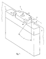
- Fig. 3 a schematic cross section is sketched showing the holding device 2, the lamp 4 and the wall 6. Due to the pivotable connection of the two holding elements 8, 10, the lamp 4, starting from a position provided for the operation, swing away from the wall 6 by an angle ⁇ . In this way, in particular a rear area of the lamp 4 is more accessible and the lamp 4 can be easily mounted and also detached from the holding device 2 and from the second holding element 10.
- a tool such as a screwdriver 20 may be provided.
- the holding device 2 may be designed such that the second holding element 10 can be pivoted or rotated relative to the first holding element 8 by at least 40 °, preferably at least 60 °.
- the second support member 10 has support means 14 which are adapted to hold the lamp 4 in its intended for operation alignment from above supporting. This makes it possible that the lamp 4, starting from any deflected position, can be easily pivoted about the pivot axis S in its intended orientation and remains in this, without requiring additional special measures to secure the position or stabilization of the lamp 4 would be required.
- a latching connection is provided between the second holding element 10 and the lamp 4, by which the lamp 4 is held on the second holding element 10, so that both the second holding element 10, and the lamp 10 may have corresponding locking elements.
- the carrying means 14 advantageously comprise at least one latching element 142, which is preferably resilient.
- the carrying means 14 can be formed from a plurality of, for example, four latching elements.
- the locking elements can be designed in this way, in that they can be pushed laterally onto the remaining second holding element 10, for example in pairs, as known per se from the prior art.
- Fig. 3 As an example, it can be provided that in the intended for operation alignment of the lamp 4 with the holding device 2, the support means 14 at least predominantly, preferably completely below a horizontal plane E are arranged, which extends through the pivot axis S. In this way, the lamp 4 depends in its intended orientation particularly stable and secure on the holding device. 2
- the luminaire 4 may have a wiring box 44, wherein the wiring box 44 has the latching elements 46 of the luminaire 4 already mentioned above.
- the lamp 4 may have a device housing 42.
- the latching elements of the luminaire 4 can also be arranged on the device housing 42.
- the second holding element 10 is not displaceable relative to the first holding element 8 along or parallel to the pivot axis S.
- the mobility of the two holding elements 8, 10 is limited to each other and thereby further simplifies the handling of the holding device 2 and the associated lamp 4, in particular in connection with their assembly and disassembly.
- the first holding element 8 comprises a plate-shaped part 82, which is intended to be brought into abutment against the wall 6. This allows a particularly simple mounting of the holding device 2 on the wall 6.
- the at least one passage opening 81 may be formed in the plate-shaped part 82.
- the second holding element 10 advantageously comprises a further plate-shaped part 104, wherein the carrying means 14 or the latching elements 142 extend from the further plate-shaped part 104 projecting downwards.
- the holding device 2 is advantageously designed such that the pivot axis S extends substantially in a plane PE , which is defined by the plate-shaped part 82 of the first holding member 8.
- substantially is to be expressed that the pivot axis S is no further than a small distance from the plane PE , for example, 10%, preferably 5% of the extension L of the second support member 10 in a section normal to the pivot axis S is.
- the first holding element 8 on a spacer 84 which is adapted to hold the lamp 4 in a designated position for operation at a distance A from the wall 6.
- the clearance A secured by the spacer 84 can be, for example, between 5% and 50%, preferably between 10% and 25%, of the extension L of the second holding element 10.
- a second holding element 10 'according to such a variant is in Fig. 3 is indicated in a deflected by the angle ⁇ position.
- the second holding element 10 has a passage opening 102 for carrying out an electrical supply line for the light 4. This makes it particularly easy to produce an electrical supply to the light 4.
Landscapes
- Engineering & Computer Science (AREA)
- General Engineering & Computer Science (AREA)
- Fastening Of Light Sources Or Lamp Holders (AREA)
Description
Die Erfindung betrifft eine Haltevorrichtung zur Halterung einer Leuchte an einer Wand, wobei die Haltevorrichtung ein erstes Halteelement aufweist, das dafür vorgesehen ist, an der Wand fixiert zu werden, sowie ein zweites Halteelement, das dafür vorgesehen ist, mit der Leuchte lagefixiert verbunden zu werden. Weiterhin betrifft die Erfindung eine Leuchte, die mit einer solchen Haltevorrichtung verbunden ist.The invention relates to a holding device for mounting a lamp to a wall, wherein the holding device has a first holding element, which is intended to be fixed to the wall, and a second holding element, which is intended to be fixed in position fixed to the lamp , Furthermore, the invention relates to a luminaire, which is connected to such a holding device.
Eine entsprechende Haltevorrichtung vertreibt die Anmelderin in Verbindung mit einer Notleuchte ("ECOSIGN AW"). Das erste Halteelement ist hierbei durch ein plattenförmiges Element gegeben, das an der Wand festgeschraubt wird und das zweite Halteelement durch ein weiteres plattenförmiges Element, das im rechten Winkel mit dem ersten Halteelement verbunden ist, so dass hierdurch ein Montagewinkel für die Notleuchte gebildet ist. Das weitere plattenförmige Element ist in der für den Betrieb der Leuchte vorgesehenen Orientierung der Haltevorrichtung horizontal ausgerichtet. Weiterhin sind zwei Schnappfedern vorgesehen, die seitlich auf das weitere plattenförmige Element aufgeschoben werden. Diese Schnappfedern weisen Vorsprünge auf, die dafür vorgesehen sind, rastend und haltend hinter entsprechend ausgebildete Vorsprünge im oberen Bereich der Leuchte zu greifen.A corresponding holding device distributes the applicant in conjunction with an emergency light ("ECOSIGN AW"). The first holding element is in this case given by a plate-shaped element which is screwed to the wall and the second holding element by another plate-shaped element which is connected at right angles to the first holding element, so that in this way a mounting bracket for the emergency light is formed. The further plate-shaped element is aligned horizontally in the intended for the operation of the lamp orientation of the holding device. Furthermore, two snap springs are provided, which are pushed laterally onto the further plate-shaped element. These snap springs have projections which are designed to engage and latch behind correspondingly formed projections in the upper region of the lamp.
In der Praxis hat sich herausgestellt, dass ein Montieren und insbesondere Lösen bzw. Demontieren der Leuchte von der Haltevorrichtung bzw. von den beiden Schnappfedern aufgrund der räumlichen Beengtheit nur schwer durchzuführen ist. Ein erartiges Lösen ist im Allgemeinen beispielsweise zum Austausch eines in der Leuchte befindlichen Akkumulators erforderlich.In practice, it has been found that mounting and in particular disassembly or disassembly of the lamp from the holding device or from the two snap springs is difficult to perform due to the spatial confinement. An erartiges solving is generally required, for example, to replace a battery located in the light.
Aus der
Aus der
Aus den Schriften
Der Erfindung liegt die Aufgabe zugrunde, eine entsprechende verbesserte, bedienungsfreundliche Haltevorrichtung anzugeben. Insbesondere soll ein Montieren der Leuchte an der Haltevorrichtung und ein Lösen bzw. Demontieren der Leuchte von der Haltevorrichtung erleichtert sein. Außerdem soll eine Leuchte angegeben werden, die mit einer solchen Haltevorrichtung verbunden ist.The invention has for its object to provide a corresponding improved, easy-to-use holding device. In particular, a mounting of the lamp to the fixture and a release or disassembly of the light of the holding device to be relieved. In addition, a lamp is to be specified, which is connected to such a holding device.
Diese Aufgabe wird gemäß der Erfindung mit den in den unabhängigen Ansprüchen angegebenen Gegenständen gelöst. Besondere Ausführungsarten der Erfindung sind in den abhängigen Ansprüchen angegeben.This object is achieved according to the invention with the objects specified in the independent claims. Particular embodiments of the invention are indicated in the dependent claims.
Gemäß der Erfindung ist eine Haltevorrichtung zur Halterung einer Leuchte an einer Wand vorgesehen, die ein erstes Halteelement aufweist, das dafür vorgesehen ist, an der Wand fixiert zu werden, sowie ein zweites Halteelement, das dafür vorgesehen ist, mit der Leuchte lagefixiert verbunden zu werden. Das zweite Halteelement ist dabei gegenüber dem ersten Halteelement um eine Schwenkachse schwenkbar angeordnet.According to the invention, a holding device is provided for mounting a lamp on a wall, which has a first holding element which is intended to be fixed to the wall, and a second holding element, which is intended to be fixed in position fixed to the lamp , The second holding element is arranged pivotable relative to the first holding element about a pivot axis.
Durch die schwenkbare Ausgestaltung lässt sich erzielen, dass die Leuchte, ausgehend von einer für den Betrieb vorgesehenen Stellung, von der Wand weg geschwenkt werden kann, so dass ein rückwärtiger Bereich der Leuchte besser zugänglich ist. Hierdurch ist ermöglicht, dass sich die Leuchte leichter an der Haltevorrichtung montieren und von der Haltevorrichtung, genauer von dem zweiten Halteelement lösen bzw. demontieren lässt.The pivotable design makes it possible to achieve that the luminaire, starting from a position provided for operation, can be pivoted away from the wall so that a rearward region of the luminaire is more accessible. This makes it possible for the luminaire to be mounted more easily on the holding device and to be detached or dismounted from the holding device, more precisely from the second holding element.
Erfindungsgemäß weist das zweite Halteelement Tragemittel auf, die dazu ausgebildet sind, die Leuchte in ihrer für den Betrieb vorgesehenen Ausrichtung von oben tragend zu halten. Hierdurch lässt sich erzielen, dass die mit der Haltevorrichtung verbundene Leuchte in der für den Betrieb vorgesehenen Position stabil verbleibt.According to the invention, the second holding element on carrying means, which are adapted to hold the lamp in its intended for operation alignment from above supporting. This makes it possible to achieve that the luminaire connected to the holding device remains stable in the position intended for operation.
Vorzugsweise weisen dabei die Tragemittel wenigstens ein Rastelement auf. Hierdurch ist eine besonders einfach herzustellende Verbindung zwischen dem zweiten Halteelement und der Leuchte ermöglicht, insbesondere wenn das Rastelement dabei federnd gestaltet ist.Preferably, the support means have at least one latching element. In this way, a connection between the second retaining element and the luminaire which is particularly easy to manufacture is made possible, in particular if the latching element is designed to be resilient.
Erfindungsgemäß ist die Haltevorrichtung derart gestaltet, dass die Tragemittel, wenn die Haltevorrichtung wie vorgesehen mit der Leuchte verbunden ist und die Leuchte dabei wie vorgesehen für den Betrieb ausgerichtet ist, zumindest überwiegend, vorzugsweise vollständig unterhalb einer horizontalen Ebene angeordnet sind, die durch die Schwenkachse verläuft.According to the invention, the holding device is configured in such a way that, when the holding device is connected to the luminaire as intended and the luminaire is oriented as intended for operation, the carrying means, at least predominantly, preferably are arranged completely below a horizontal plane which passes through the pivot axis.
Eine besonders einfache Handhabung ist ermöglicht, wenn das zweite Halteelement gegenüber dem ersten Halteelement längs bzw. parallel zu der Schwenkachse nicht verschiebbar gelagert ist.A particularly simple handling is made possible when the second holding element is not displaceable relative to the first holding element along or parallel to the pivot axis.
Erfindungsgemäß umfasst das erste Halteelement einen plattenförmigen Teil, der dafür vorgesehen ist, in Anlage an die Wand gebracht zu werden. Dies ermöglicht eine einfache Montage an der Wand. Dabei ist die Haltevorrichtung derart gestaltet, dass die Schwenkachse im Wesentlichen in einer Ebene verläuft, die durch den plattenförmigen Teil festgelegt ist. Dabei ist die Schwenkachse nicht weiter als 10% der Erstreckung des zweiten Halteelements in einem Schnitt normal zu der Schwenkachse von der Ebene entfernt. Auf diese Weise lässt sich durch Schwenken der Leuchte ein besonders großer Freiraum schaffen, so dass die rückwärtige Zugänglichkeit zur Montage und Demontage der Leuchte weitergehend verbessert ist.According to the invention, the first holding element comprises a plate-shaped part, which is intended to be brought into abutment against the wall. This allows easy mounting on the wall. In this case, the holding device is designed such that the pivot axis extends substantially in a plane which is defined by the plate-shaped part. In this case, the pivot axis is not more than 10% of the extension of the second holding element in a section normal to the pivot axis away from the plane. In this way, by pivoting the lamp create a particularly large space, so that the rear accessibility for mounting and dismounting of the lamp is further improved.
Vorzugsweise weist das erste Halteelement einen Abstandhalter auf, der dazu ausgebildet ist, die Leuchte in einer für den Betrieb vorgesehenen Stellung in einem Abstand von der Wand zu halten. Hierdurch lässt sich die Zugänglichkeit zu dem rückwärtigen Bereich der Leuchte noch weitergehend verbessern.Preferably, the first holding element has a spacer, which is adapted to keep the lamp in a position provided for the operation at a distance from the wall. As a result, the accessibility to the rear area of the lamp can be further improved.
Vorteilhaft weist das zweite Halteelement eine Durchgangsöffnung zur Durchführung einer elektrischen Zuleitung für die Leuchte auf. Hierdurch lässt sich die Montage, insbesondere die Herstellung der elektrischen Zuleitung der Leuchte vereinfachen.Advantageously, the second holding element has a passage opening for carrying out an electrical supply line for the luminaire. As a result, the assembly, in particular the production of the electrical supply of the lamp can be simplified.
Gemäß einem zweiten Aspekt der Erfindung ist eine Leuchte, insbesondere in Form einer Notleuchte, vorgesehen, die mit einer erfindungsgemäßen Haltevorrichtung verbunden ist. Dabei ist die Gestaltung vorzugsweise so, dass die Schwenkachse in einer für den Betrieb vorgesehenen Stellung waagrecht verlaufend orientiert ist.According to a second aspect of the invention, a lamp, in particular in the form of an emergency light, is provided, which is connected to a holding device according to the invention. In this case, the design is preferably such that the pivot axis is oriented horizontally in a position provided for operation.
Die Erfindung wird im Folgenden anhand von Ausführungsbeispielen und mit Bezug auf die Zeichnungen näher erläutert. Es zeigen:
- Fig. 1
- eine Skizze eines Ausführungsbeispiels einer erfindungsgemäßen Haltevorrichtung mit einer daran befestigten Leuchte,
- Fig. 2
- eine perspektivische Skizze der Haltevorrichtung in separierter Form und
- Fig. 3
- eine entsprechende Querschnittskizze.
- Fig. 1
- a sketch of an embodiment of a holding device according to the invention with an attached light,
- Fig. 2
- a perspective sketch of the holding device in a separate form and
- Fig. 3
- a corresponding cross-sectional sketch.
Die Haltevorrichtung 2 ist zur Halterung der Leuchte 4 an einer Wand 6, insbesondere an einer vertikal verlaufenden Wand 6 vorgesehen und weist ein erstes Halteelement 8 auf, das dafür vorgesehen ist, an der Wand 6 fixiert zu werden, sowie ein zweites Halteelement 10, das dafür vorgesehen ist, mit der Leuchte 4 lagefixiert verbunden zu werden. Mit "lagefixiert" sei dabei insbesondere zum Ausdruck gebracht, dass die vorgesehene Verbindungsstruktur zwischen der Leuchte 4 und dem zweiten Halteelement 10 keine Lageranordnung für eine Relativbewegung zwischen diesen beiden Teilen aufweist bzw. keine beweglichen Verbindungsmittel.The
Das erste Halteelement 8 kann wenigstens eine Durchgangsöffnung 81 aufweisen, die für eine feste Verbindung, beispielsweise eine Schraubverbindung mit der Wand 6 vorgesehen ist.The first retaining element 8 may have at least one passage opening 81, which is provided for a fixed connection, for example a screw connection with the
Das zweite Halteelement 10 ist dabei gegenüber dem ersten Halteelement 8 um eine Schwenkachse S, insbesondere Drehachse schwenkbar bzw. drehbar angeordnet. Zu der Verbindung des zweiten Halteelements 10 mit dem ersten Halteelement 8 kann insbesondere ein Bolzen 12 vorgesehen sein, der in der Schwenkachse S bzw. Drehachse angeordnet ist. Es kann insbesondere vorgesehen sein, dass das zweite Halteelement 10 gegenüber dem ersten Halteelement 8 lediglich um die Schwenkachse S beweglich bzw. schwenk- oder drehbar angeordnet ist. Durch den Bolzen 12 und dessen Lagerung an dem ersten Halteelement 8 und dem zweiten Halteelement 10 kann dementsprechend ein Scharnier gebildet sein.The
Vorzugsweise ist die Ausgestaltung der Haltevorrichtung 2 derart, dass die Schwenk- bzw. Drehachse S in der vorgesehenen Ausrichtung der Haltevorrichtung 2 waagrecht verlaufend orientiert ist.Preferably, the embodiment of the
In
Beispielsweise kann die Haltevorrichtung 2 derart gestaltet sein, dass das zweite Halteelement 10 gegenüber dem ersten Halteelement 8 um mindestens 40°, vorzugsweise mindestens 60° geschwenkt bzw. gedreht werden kann.For example, the holding
Vorzugsweise weist das zweite Halteelement 10 Tragemittel 14 auf, die dazu ausgebildet sind, die Leuchte 4 in ihrer für den Betrieb vorgesehenen Ausrichtung von oben tragend zu halten. Hierdurch ist ermöglicht, dass die Leuchte 4, ausgehend von einer beliebigen ausgelenkten Stellung, einfach um die Schwenkachse S in ihre vorgesehene Ausrichtung geschwenkt werden kann und in dieser verbleibt, ohne dass hierfür zusätzliche besondere Maßnahmen zur Lagesicherung oder Stabilisierung der Leuchte 4 erforderlich wären.Preferably, the
Vorteilhaft ist zwischen dem zweiten Halteelement 10 und der Leuchte 4 eine Rastverbindung vorgesehen, durch die die Leuchte 4 an dem zweiten Halteelement 10 gehalten ist, so dass sowohl das zweite Halteelement 10, als auch die Leuchte 10 entsprechende Rastelemente aufweisen können. Dementsprechend umfassen die Tragemittel 14 vorteilhaft wenigstens ein Rastelement 142, das bevorzugt federnd gestaltet ist. Insbesondere können die Tragemittel 14 aus mehreren, beispielsweise vier Rastelementen gebildet sein. Die Rastelemente können dabei derart ausgestaltet sein, dass sie sich, beispielsweise paarweise miteinander verbunden, wie an sich aus dem Stand der Technik bekannt, seitlich auf das restliche zweite Halteelement 10 aufschieben lassen.Advantageously, a latching connection is provided between the
Wie aus
Wie aus
Vorteilhaft ist das zweite Halteelement 10 gegenüber dem ersten Halteelement 8 längs bzw. parallel zu der Schwenkachse S nicht verschiebbar gelagert. Hierdurch ist die Beweglichkeit der beiden Halteelemente 8, 10 zueinander limitiert und dadurch die Handhabung der Haltevorrichtung 2 bzw. der damit verbundenen Leuchte 4, insbesondere in Zusammenhang mit ihrer Montage und Demontage weitergehend vereinfacht.Advantageously, the
Vorzugsweise umfasst das erste Halteelement 8 einen plattenförmigen Teil 82, der dafür vorgesehen ist, in Anlage an die Wand 6 gebracht zu werden. Dies ermöglicht eine besonders einfache Montage der Haltevorrichtung 2 an der Wand 6. Dabei kann insbesondere die wenigstens eine Durchgangsöffnung 81 in dem plattenförmigen Teil 82 ausgebildet sein.Preferably, the first holding element 8 comprises a plate-shaped
Das zweite Halteelement 10 umfasst vorteilhaft einen weiteren plattenförmigen Teil 104, wobei sich die Tragemittel 14 bzw. die Rastelemente 142 von dem weiteren plattenförmigen Teil 104 nach unten abstehend erstrecken.The
Wie aus
Auf diese Weise lässt sich durch Schwenken der Leuchte 4 ein besonders großer Freiraum schaffen, so dass die Zugänglichkeit zum rückwärtigen Bereich der Leuchte 4 weitergehend verbessert ist.In this way, can be created by pivoting the
Weiterhin vorteilhaft weist das erste Halteelement 8 einen Abstandhalter 84 auf, der dazu ausgebildet ist, die Leuchte 4 in einer für den Betrieb vorgesehenen Stellung in einem Abstand A von der Wand 6 zu halten. Dabei kann der durch den Abstandhalter 84 sichergestellte Abstand A beispielsweise zwischen 5% und 50%, vorzugsweise zwischen 10% und 25% der Erstreckung L des zweiten Halteelements 10 betragen.Further advantageously, the first holding element 8 on a
Es kann aber auch eine Ausführung ohne einen solchen Abstandhalter vorgesehen sein; in diesem Fall kann eine unmittelbare Anlage der Leuchte 4 an der Wand 6 vorgesehen sin. Ein zweites Halteelement 10' gemäß einer solchen Variante ist in
Vorteilhaft weist das zweite Halteelement 10 eine Durchgangsöffnung 102 zur Durchführung einer elektrischen Zuleitung für die Leuchte 4 auf. Hierdurch lässt sich besonders einfach eine elektrische Zuleitung zu der Leuchte 4 herstellen.Advantageously, the
Claims (10)
- A holding device for holding a luminaire (4) on a wall (6), having- a first holding element (8) which is intended to be fixed on the wall (6), and- a second holding element (10) which is intended to be connected to the luminaire (4) in a positionally fixed manner,wherein the second holding element (10) is arranged so that it can be swivelled with respect to the first holding element (8) about a swivel axis (S),
wherein the second holding element (10) has supporting means (14) which are formed to hold the luminaire (4) supporting it from above in its intended alignment for operation,
wherein the holding device is configured in such a way that, when the holding device, as intended, is connected to the luminaire (4) and the luminaire (4) then, as intended, is aligned for operation, the supporting means (14) are arranged at least predominantly below a horizontal plane (E) extending through the swivel axis (S),
wherein the first holding element (8) includes a plate-shaped portion (82) which is intended to be brought into abutment with the wall (6),
characterised in that
the holding device is configured in such a way that the swivel axis (S) extends substantially in a plane (PE) that is defined by the plate-shaped portion (82), wherein the swivel axis (S) is not further than 10% of the extent (L) of the second holding element (10), in a section normal to the swivel axis (S), away from the plane (PE). - A holding device according to claim 1,
which is configured in such a way that, when the holding device, as intended, is connected to the luminaire (4) and the luminaire (4) then, as intended, is aligned for operation, the supporting means (14) are arranged completely below the horizontal plane (E) extending through the swivel axis (S). - A holding device according to claim 1 or 2,
in which the swivel axis (S) is not further than 5% of the extent (L) of the second holding element (10), in a section normal to the swivel axis (S), away from the plane (PE). - A holding device according to one of the preceding claims,
in which the supporting means (14) have at least one latching element (142). - A holding device according to claim 4,
in which the latching element (142) is configured in a resilient manner. - A holding device according to one of the preceding claims,
in which the second holding element (10) is mounted with respect to the first holding element (8) so that it cannot be displaced along or parallel to the swivel axis (S). - A holding device according to one of the preceding claims,
in which the first holding element (8) has a spacer (84) which is formed to hold the luminaire (4) in an intended position for operation at a distance (A) from the wall (6). - A holding device according to one of the preceding claims,
in which the second holding element (10) has a through-opening (102) for guiding through an electrical supply line for the luminaire (4). - A luminaire, in particular in the form of an emergency luminaire, connected to a holding device (2) according to one of the preceding claims.
- A luminaire and a holding device according to claim 9,
wherein the swivel axis (S) is oriented so that it extends horizontally in an intended position for operation.
Applications Claiming Priority (1)
| Application Number | Priority Date | Filing Date | Title |
|---|---|---|---|
| DE202010013177U DE202010013177U1 (en) | 2010-12-21 | 2010-12-21 | Holding device for a light |
Publications (3)
| Publication Number | Publication Date |
|---|---|
| EP2469162A2 EP2469162A2 (en) | 2012-06-27 |
| EP2469162A3 EP2469162A3 (en) | 2013-07-03 |
| EP2469162B1 true EP2469162B1 (en) | 2014-08-20 |
Family
ID=45524256
Family Applications (1)
| Application Number | Title | Priority Date | Filing Date |
|---|---|---|---|
| EP20110194492 Not-in-force EP2469162B1 (en) | 2010-12-21 | 2011-12-20 | Holding device for a light |
Country Status (2)
| Country | Link |
|---|---|
| EP (1) | EP2469162B1 (en) |
| DE (1) | DE202010013177U1 (en) |
Families Citing this family (1)
| Publication number | Priority date | Publication date | Assignee | Title |
|---|---|---|---|---|
| DE202012104636U1 (en) | 2012-11-29 | 2014-03-03 | Zumtobel Lighting Gmbh | Holder for a luminaire and luminaire arrangement |
Family Cites Families (11)
| Publication number | Priority date | Publication date | Assignee | Title |
|---|---|---|---|---|
| US4051362A (en) * | 1976-03-08 | 1977-09-27 | Guggemos Kenneth F | Wall mounted hinged base |
| DE2748606C3 (en) * | 1977-10-29 | 1982-01-21 | Abke, Hermann, 4972 Löhne | Fixing device for a lamp |
| DE3008307A1 (en) * | 1980-03-04 | 1981-09-17 | Böllhof & Co, 4800 Bielefeld | Profiled section fixing device - comprises clips with pairs of arms engaging with different sections and spread apart |
| AT388986B (en) * | 1987-10-02 | 1989-09-25 | Zumtobel Ag | MOUNTED LUMINAIRE |
| DE9209335U1 (en) * | 1992-07-11 | 1992-09-03 | Licentia Patent-Verwaltungs-Gmbh, 6000 Frankfurt | Holding device of a wall lamp |
| US5642934A (en) * | 1995-09-13 | 1997-07-01 | Hadco Division Of The Genlyte Group Incorporated | Adjustable outdoor light |
| US6095665A (en) * | 1998-04-03 | 2000-08-01 | Drake; Michael | Outdoor lamp |
| DE20013280U1 (en) * | 2000-08-02 | 2001-12-13 | Kotzolt-Leuchten L. & G. Kotzolt GmbH & Co KG, 32657 Lemgo | Information lamp |
| US6905222B1 (en) * | 2002-04-02 | 2005-06-14 | Genlyte Thomas Group Llc | Thermal isolation luminaire and wall mount system |
| US7434969B2 (en) * | 2004-01-21 | 2008-10-14 | The Flewelling Ford Family Trust | Multi-function light support |
| EP1847769B1 (en) * | 2006-04-22 | 2008-09-24 | Matthias Dipl.-Phys. Ing. Gimpel | Mounting system, especially for lamps |
-
2010
- 2010-12-21 DE DE202010013177U patent/DE202010013177U1/en not_active Expired - Lifetime
-
2011
- 2011-12-20 EP EP20110194492 patent/EP2469162B1/en not_active Not-in-force
Also Published As
| Publication number | Publication date |
|---|---|
| EP2469162A3 (en) | 2013-07-03 |
| EP2469162A2 (en) | 2012-06-27 |
| DE202010013177U1 (en) | 2012-03-26 |
Similar Documents
| Publication | Publication Date | Title |
|---|---|---|
| EP2248503B1 (en) | Medical supply unit with lockable adapters | |
| EP2427401B1 (en) | Suspension element of a trailing cable assembly | |
| EP3161274B1 (en) | Device for installing and removing a component of a gas turbine | |
| DE60106194T2 (en) | SERVICE DEVICE | |
| EP3805576A2 (en) | Coupling | |
| WO2018157885A1 (en) | Protective separator for a right angle plug connection | |
| EP3406952A1 (en) | Pivotable cable holder | |
| EP2385596B1 (en) | Device comprising a tube and a housing mountable to the tube for an electricity charging box for electric vehicles | |
| DE102010026679A1 (en) | Arrangement for pivotally connecting a first housing part with a second housing part of a distribution cabinet and distribution cabinet | |
| DE202013101819U1 (en) | System for mounting a ceiling-mounted luminaire on a ceiling | |
| EP3396655A1 (en) | Led panel | |
| EP2469162B1 (en) | Holding device for a light | |
| EP3084903B1 (en) | Framework for an electrical cabinet with pivotable holders for distribution busbars and manufacturing method for a cabinet | |
| EP1968033B1 (en) | Display device with holder device | |
| EP3408156B1 (en) | Ceiling module for a vehicle | |
| DE202010015763U1 (en) | Device for positioning at least one circular plug | |
| EP3644465A1 (en) | Cable tray and device for connecting cable trays | |
| EP3209934B1 (en) | Downlight | |
| EP3461963A1 (en) | Supporting construction system and system of connecting elements for the supporting construction | |
| EP2879472B1 (en) | Housing for a control device | |
| EP3737582B1 (en) | Clamp and contact wire carrier assembly | |
| DE19705404C2 (en) | Protective housing for optical devices with a holding body for attachment to a mounting surface | |
| EP2578891B1 (en) | Adapter | |
| DE102009055277B4 (en) | Cabel Canal | |
| EP2263292B1 (en) | Apparatus for strain relief |
Legal Events
| Date | Code | Title | Description |
|---|---|---|---|
| AK | Designated contracting states |
Kind code of ref document: A2 Designated state(s): AL AT BE BG CH CY CZ DE DK EE ES FI FR GB GR HR HU IE IS IT LI LT LU LV MC MK MT NL NO PL PT RO RS SE SI SK SM TR |
|
| AX | Request for extension of the european patent |
Extension state: BA ME |
|
| PUAI | Public reference made under article 153(3) epc to a published international application that has entered the european phase |
Free format text: ORIGINAL CODE: 0009012 |
|
| PUAL | Search report despatched |
Free format text: ORIGINAL CODE: 0009013 |
|
| AK | Designated contracting states |
Kind code of ref document: A3 Designated state(s): AL AT BE BG CH CY CZ DE DK EE ES FI FR GB GR HR HU IE IS IT LI LT LU LV MC MK MT NL NO PL PT RO RS SE SI SK SM TR |
|
| AX | Request for extension of the european patent |
Extension state: BA ME |
|
| RIC1 | Information provided on ipc code assigned before grant |
Ipc: F21V 21/02 20060101AFI20130524BHEP |
|
| 17P | Request for examination filed |
Effective date: 20131205 |
|
| RBV | Designated contracting states (corrected) |
Designated state(s): AL AT BE BG CH CY CZ DE DK EE ES FI FR GB GR HR HU IE IS IT LI LT LU LV MC MK MT NL NO PL PT RO RS SE SI SK SM TR |
|
| GRAP | Despatch of communication of intention to grant a patent |
Free format text: ORIGINAL CODE: EPIDOSNIGR1 |
|
| INTG | Intention to grant announced |
Effective date: 20140324 |
|
| GRAS | Grant fee paid |
Free format text: ORIGINAL CODE: EPIDOSNIGR3 |
|
| GRAA | (expected) grant |
Free format text: ORIGINAL CODE: 0009210 |
|
| AK | Designated contracting states |
Kind code of ref document: B1 Designated state(s): AL AT BE BG CH CY CZ DE DK EE ES FI FR GB GR HR HU IE IS IT LI LT LU LV MC MK MT NL NO PL PT RO RS SE SI SK SM TR |
|
| REG | Reference to a national code |
Ref country code: GB Ref legal event code: FG4D Free format text: NOT ENGLISH |
|
| REG | Reference to a national code |
Ref country code: CH Ref legal event code: EP Ref country code: CH Ref legal event code: NV Representative=s name: FIAMMENGHI-FIAMMENGHI, CH |
|
| REG | Reference to a national code |
Ref country code: AT Ref legal event code: REF Ref document number: 683678 Country of ref document: AT Kind code of ref document: T Effective date: 20140915 |
|
| REG | Reference to a national code |
Ref country code: IE Ref legal event code: FG4D Free format text: LANGUAGE OF EP DOCUMENT: GERMAN |
|
| REG | Reference to a national code |
Ref country code: DE Ref legal event code: R096 Ref document number: 502011004096 Country of ref document: DE Effective date: 20141002 |
|
| REG | Reference to a national code |
Ref country code: NL Ref legal event code: VDEP Effective date: 20140820 |
|
| REG | Reference to a national code |
Ref country code: LT Ref legal event code: MG4D |
|
| PG25 | Lapsed in a contracting state [announced via postgrant information from national office to epo] |
Ref country code: FI Free format text: LAPSE BECAUSE OF FAILURE TO SUBMIT A TRANSLATION OF THE DESCRIPTION OR TO PAY THE FEE WITHIN THE PRESCRIBED TIME-LIMIT Effective date: 20140820 Ref country code: LT Free format text: LAPSE BECAUSE OF FAILURE TO SUBMIT A TRANSLATION OF THE DESCRIPTION OR TO PAY THE FEE WITHIN THE PRESCRIBED TIME-LIMIT Effective date: 20140820 Ref country code: SE Free format text: LAPSE BECAUSE OF FAILURE TO SUBMIT A TRANSLATION OF THE DESCRIPTION OR TO PAY THE FEE WITHIN THE PRESCRIBED TIME-LIMIT Effective date: 20140820 Ref country code: NO Free format text: LAPSE BECAUSE OF FAILURE TO SUBMIT A TRANSLATION OF THE DESCRIPTION OR TO PAY THE FEE WITHIN THE PRESCRIBED TIME-LIMIT Effective date: 20141120 Ref country code: ES Free format text: LAPSE BECAUSE OF FAILURE TO SUBMIT A TRANSLATION OF THE DESCRIPTION OR TO PAY THE FEE WITHIN THE PRESCRIBED TIME-LIMIT Effective date: 20140820 Ref country code: PT Free format text: LAPSE BECAUSE OF FAILURE TO SUBMIT A TRANSLATION OF THE DESCRIPTION OR TO PAY THE FEE WITHIN THE PRESCRIBED TIME-LIMIT Effective date: 20141222 Ref country code: BG Free format text: LAPSE BECAUSE OF FAILURE TO SUBMIT A TRANSLATION OF THE DESCRIPTION OR TO PAY THE FEE WITHIN THE PRESCRIBED TIME-LIMIT Effective date: 20141120 Ref country code: GR Free format text: LAPSE BECAUSE OF FAILURE TO SUBMIT A TRANSLATION OF THE DESCRIPTION OR TO PAY THE FEE WITHIN THE PRESCRIBED TIME-LIMIT Effective date: 20141121 |
|
| PG25 | Lapsed in a contracting state [announced via postgrant information from national office to epo] |
Ref country code: LV Free format text: LAPSE BECAUSE OF FAILURE TO SUBMIT A TRANSLATION OF THE DESCRIPTION OR TO PAY THE FEE WITHIN THE PRESCRIBED TIME-LIMIT Effective date: 20140820 Ref country code: HR Free format text: LAPSE BECAUSE OF FAILURE TO SUBMIT A TRANSLATION OF THE DESCRIPTION OR TO PAY THE FEE WITHIN THE PRESCRIBED TIME-LIMIT Effective date: 20140820 Ref country code: RS Free format text: LAPSE BECAUSE OF FAILURE TO SUBMIT A TRANSLATION OF THE DESCRIPTION OR TO PAY THE FEE WITHIN THE PRESCRIBED TIME-LIMIT Effective date: 20140820 Ref country code: IS Free format text: LAPSE BECAUSE OF FAILURE TO SUBMIT A TRANSLATION OF THE DESCRIPTION OR TO PAY THE FEE WITHIN THE PRESCRIBED TIME-LIMIT Effective date: 20141220 |
|
| PG25 | Lapsed in a contracting state [announced via postgrant information from national office to epo] |
Ref country code: NL Free format text: LAPSE BECAUSE OF FAILURE TO SUBMIT A TRANSLATION OF THE DESCRIPTION OR TO PAY THE FEE WITHIN THE PRESCRIBED TIME-LIMIT Effective date: 20140820 |
|
| PG25 | Lapsed in a contracting state [announced via postgrant information from national office to epo] |
Ref country code: RO Free format text: LAPSE BECAUSE OF FAILURE TO SUBMIT A TRANSLATION OF THE DESCRIPTION OR TO PAY THE FEE WITHIN THE PRESCRIBED TIME-LIMIT Effective date: 20140820 Ref country code: IT Free format text: LAPSE BECAUSE OF FAILURE TO SUBMIT A TRANSLATION OF THE DESCRIPTION OR TO PAY THE FEE WITHIN THE PRESCRIBED TIME-LIMIT Effective date: 20140820 Ref country code: SK Free format text: LAPSE BECAUSE OF FAILURE TO SUBMIT A TRANSLATION OF THE DESCRIPTION OR TO PAY THE FEE WITHIN THE PRESCRIBED TIME-LIMIT Effective date: 20140820 Ref country code: DK Free format text: LAPSE BECAUSE OF FAILURE TO SUBMIT A TRANSLATION OF THE DESCRIPTION OR TO PAY THE FEE WITHIN THE PRESCRIBED TIME-LIMIT Effective date: 20140820 Ref country code: CZ Free format text: LAPSE BECAUSE OF FAILURE TO SUBMIT A TRANSLATION OF THE DESCRIPTION OR TO PAY THE FEE WITHIN THE PRESCRIBED TIME-LIMIT Effective date: 20140820 Ref country code: EE Free format text: LAPSE BECAUSE OF FAILURE TO SUBMIT A TRANSLATION OF THE DESCRIPTION OR TO PAY THE FEE WITHIN THE PRESCRIBED TIME-LIMIT Effective date: 20140820 |
|
| REG | Reference to a national code |
Ref country code: DE Ref legal event code: R097 Ref document number: 502011004096 Country of ref document: DE |
|
| PG25 | Lapsed in a contracting state [announced via postgrant information from national office to epo] |
Ref country code: PL Free format text: LAPSE BECAUSE OF FAILURE TO SUBMIT A TRANSLATION OF THE DESCRIPTION OR TO PAY THE FEE WITHIN THE PRESCRIBED TIME-LIMIT Effective date: 20140820 |
|
| PLBE | No opposition filed within time limit |
Free format text: ORIGINAL CODE: 0009261 |
|
| STAA | Information on the status of an ep patent application or granted ep patent |
Free format text: STATUS: NO OPPOSITION FILED WITHIN TIME LIMIT |
|
| PG25 | Lapsed in a contracting state [announced via postgrant information from national office to epo] |
Ref country code: BE Free format text: LAPSE BECAUSE OF NON-PAYMENT OF DUE FEES Effective date: 20141231 |
|
| 26N | No opposition filed |
Effective date: 20150521 |
|
| PG25 | Lapsed in a contracting state [announced via postgrant information from national office to epo] |
Ref country code: LU Free format text: LAPSE BECAUSE OF FAILURE TO SUBMIT A TRANSLATION OF THE DESCRIPTION OR TO PAY THE FEE WITHIN THE PRESCRIBED TIME-LIMIT Effective date: 20141220 |
|
| REG | Reference to a national code |
Ref country code: IE Ref legal event code: MM4A |
|
| PG25 | Lapsed in a contracting state [announced via postgrant information from national office to epo] |
Ref country code: IE Free format text: LAPSE BECAUSE OF NON-PAYMENT OF DUE FEES Effective date: 20141220 |
|
| PG25 | Lapsed in a contracting state [announced via postgrant information from national office to epo] |
Ref country code: SI Free format text: LAPSE BECAUSE OF FAILURE TO SUBMIT A TRANSLATION OF THE DESCRIPTION OR TO PAY THE FEE WITHIN THE PRESCRIBED TIME-LIMIT Effective date: 20140820 |
|
| REG | Reference to a national code |
Ref country code: FR Ref legal event code: PLFP Year of fee payment: 5 |
|
| PG25 | Lapsed in a contracting state [announced via postgrant information from national office to epo] |
Ref country code: SM Free format text: LAPSE BECAUSE OF FAILURE TO SUBMIT A TRANSLATION OF THE DESCRIPTION OR TO PAY THE FEE WITHIN THE PRESCRIBED TIME-LIMIT Effective date: 20140820 |
|
| PG25 | Lapsed in a contracting state [announced via postgrant information from national office to epo] |
Ref country code: MC Free format text: LAPSE BECAUSE OF FAILURE TO SUBMIT A TRANSLATION OF THE DESCRIPTION OR TO PAY THE FEE WITHIN THE PRESCRIBED TIME-LIMIT Effective date: 20140820 |
|
| PG25 | Lapsed in a contracting state [announced via postgrant information from national office to epo] |
Ref country code: CY Free format text: LAPSE BECAUSE OF FAILURE TO SUBMIT A TRANSLATION OF THE DESCRIPTION OR TO PAY THE FEE WITHIN THE PRESCRIBED TIME-LIMIT Effective date: 20140820 |
|
| PG25 | Lapsed in a contracting state [announced via postgrant information from national office to epo] |
Ref country code: HU Free format text: LAPSE BECAUSE OF FAILURE TO SUBMIT A TRANSLATION OF THE DESCRIPTION OR TO PAY THE FEE WITHIN THE PRESCRIBED TIME-LIMIT; INVALID AB INITIO Effective date: 20111220 Ref country code: TR Free format text: LAPSE BECAUSE OF FAILURE TO SUBMIT A TRANSLATION OF THE DESCRIPTION OR TO PAY THE FEE WITHIN THE PRESCRIBED TIME-LIMIT Effective date: 20140820 Ref country code: MT Free format text: LAPSE BECAUSE OF FAILURE TO SUBMIT A TRANSLATION OF THE DESCRIPTION OR TO PAY THE FEE WITHIN THE PRESCRIBED TIME-LIMIT Effective date: 20140820 |
|
| REG | Reference to a national code |
Ref country code: FR Ref legal event code: PLFP Year of fee payment: 6 |
|
| PGFP | Annual fee paid to national office [announced via postgrant information from national office to epo] |
Ref country code: CH Payment date: 20161223 Year of fee payment: 6 Ref country code: GB Payment date: 20161228 Year of fee payment: 6 |
|
| PGFP | Annual fee paid to national office [announced via postgrant information from national office to epo] |
Ref country code: AT Payment date: 20170105 Year of fee payment: 6 Ref country code: FR Payment date: 20161229 Year of fee payment: 6 |
|
| PG25 | Lapsed in a contracting state [announced via postgrant information from national office to epo] |
Ref country code: MK Free format text: LAPSE BECAUSE OF FAILURE TO SUBMIT A TRANSLATION OF THE DESCRIPTION OR TO PAY THE FEE WITHIN THE PRESCRIBED TIME-LIMIT Effective date: 20140820 |
|
| REG | Reference to a national code |
Ref country code: CH Ref legal event code: PL |
|
| REG | Reference to a national code |
Ref country code: AT Ref legal event code: MM01 Ref document number: 683678 Country of ref document: AT Kind code of ref document: T Effective date: 20171220 |
|
| GBPC | Gb: european patent ceased through non-payment of renewal fee |
Effective date: 20171220 |
|
| REG | Reference to a national code |
Ref country code: FR Ref legal event code: ST Effective date: 20180831 |
|
| REG | Reference to a national code |
Ref country code: DE Ref legal event code: R084 Ref document number: 502011004096 Country of ref document: DE |
|
| PG25 | Lapsed in a contracting state [announced via postgrant information from national office to epo] |
Ref country code: AL Free format text: LAPSE BECAUSE OF FAILURE TO SUBMIT A TRANSLATION OF THE DESCRIPTION OR TO PAY THE FEE WITHIN THE PRESCRIBED TIME-LIMIT Effective date: 20140820 Ref country code: FR Free format text: LAPSE BECAUSE OF NON-PAYMENT OF DUE FEES Effective date: 20180102 |
|
| PG25 | Lapsed in a contracting state [announced via postgrant information from national office to epo] |
Ref country code: GB Free format text: LAPSE BECAUSE OF NON-PAYMENT OF DUE FEES Effective date: 20171220 Ref country code: AT Free format text: LAPSE BECAUSE OF NON-PAYMENT OF DUE FEES Effective date: 20171220 Ref country code: CH Free format text: LAPSE BECAUSE OF NON-PAYMENT OF DUE FEES Effective date: 20171231 Ref country code: LI Free format text: LAPSE BECAUSE OF NON-PAYMENT OF DUE FEES Effective date: 20171231 |
|
| PGFP | Annual fee paid to national office [announced via postgrant information from national office to epo] |
Ref country code: DE Payment date: 20220527 Year of fee payment: 12 |
|
| P01 | Opt-out of the competence of the unified patent court (upc) registered |
Effective date: 20230530 |
|
| REG | Reference to a national code |
Ref country code: DE Ref legal event code: R119 Ref document number: 502011004096 Country of ref document: DE |