EP2468950A1 - Process and machine for drying laundry - Google Patents
Process and machine for drying laundry Download PDFInfo
- Publication number
- EP2468950A1 EP2468950A1 EP11195381A EP11195381A EP2468950A1 EP 2468950 A1 EP2468950 A1 EP 2468950A1 EP 11195381 A EP11195381 A EP 11195381A EP 11195381 A EP11195381 A EP 11195381A EP 2468950 A1 EP2468950 A1 EP 2468950A1
- Authority
- EP
- European Patent Office
- Prior art keywords
- drum
- phase
- laundry
- control system
- moisture
- Prior art date
- Legal status (The legal status is an assumption and is not a legal conclusion. Google has not performed a legal analysis and makes no representation as to the accuracy of the status listed.)
- Granted
Links
- 238000001035 drying Methods 0.000 title claims abstract description 58
- 238000000034 method Methods 0.000 title claims description 26
- 238000009423 ventilation Methods 0.000 claims description 15
- 238000010438 heat treatment Methods 0.000 claims description 14
- 238000001816 cooling Methods 0.000 claims description 12
- 230000001464 adherent effect Effects 0.000 abstract description 4
- 238000009833 condensation Methods 0.000 description 9
- 230000005494 condensation Effects 0.000 description 9
- 238000009987 spinning Methods 0.000 description 7
- XLYOFNOQVPJJNP-UHFFFAOYSA-N water Substances O XLYOFNOQVPJJNP-UHFFFAOYSA-N 0.000 description 5
- 239000004744 fabric Substances 0.000 description 4
- 230000006870 function Effects 0.000 description 3
- 238000011144 upstream manufacturing Methods 0.000 description 3
- 238000004891 communication Methods 0.000 description 2
- 230000000694 effects Effects 0.000 description 2
- 238000004519 manufacturing process Methods 0.000 description 2
- 238000005406 washing Methods 0.000 description 2
- 210000002268 wool Anatomy 0.000 description 2
- 241000282836 Camelus dromedarius Species 0.000 description 1
- 229920000742 Cotton Polymers 0.000 description 1
- 238000013019 agitation Methods 0.000 description 1
- 230000005540 biological transmission Effects 0.000 description 1
- 230000015572 biosynthetic process Effects 0.000 description 1
- 210000000085 cashmere Anatomy 0.000 description 1
- 238000012512 characterization method Methods 0.000 description 1
- 238000004140 cleaning Methods 0.000 description 1
- 239000012530 fluid Substances 0.000 description 1
- 210000004209 hair Anatomy 0.000 description 1
- 238000000703 high-speed centrifugation Methods 0.000 description 1
- 238000012423 maintenance Methods 0.000 description 1
- 210000000050 mohair Anatomy 0.000 description 1
- 230000008447 perception Effects 0.000 description 1
- 230000002093 peripheral effect Effects 0.000 description 1
- 230000001681 protective effect Effects 0.000 description 1
- 238000009877 rendering Methods 0.000 description 1
- 238000005096 rolling process Methods 0.000 description 1
Images
Classifications
-
- D—TEXTILES; PAPER
- D06—TREATMENT OF TEXTILES OR THE LIKE; LAUNDERING; FLEXIBLE MATERIALS NOT OTHERWISE PROVIDED FOR
- D06F—LAUNDERING, DRYING, IRONING, PRESSING OR FOLDING TEXTILE ARTICLES
- D06F58/00—Domestic laundry dryers
- D06F58/32—Control of operations performed in domestic laundry dryers
- D06F58/34—Control of operations performed in domestic laundry dryers characterised by the purpose or target of the control
- D06F58/36—Control of operational steps, e.g. for optimisation or improvement of operational steps depending on the condition of the laundry
- D06F58/38—Control of operational steps, e.g. for optimisation or improvement of operational steps depending on the condition of the laundry of drying, e.g. to achieve the target humidity
-
- D—TEXTILES; PAPER
- D06—TREATMENT OF TEXTILES OR THE LIKE; LAUNDERING; FLEXIBLE MATERIALS NOT OTHERWISE PROVIDED FOR
- D06F—LAUNDERING, DRYING, IRONING, PRESSING OR FOLDING TEXTILE ARTICLES
- D06F2101/00—User input for the control of domestic laundry washing machines, washer-dryers or laundry dryers
- D06F2101/20—Operation modes, e.g. delicate laundry washing programs, service modes or refreshment cycles
-
- D—TEXTILES; PAPER
- D06—TREATMENT OF TEXTILES OR THE LIKE; LAUNDERING; FLEXIBLE MATERIALS NOT OTHERWISE PROVIDED FOR
- D06F—LAUNDERING, DRYING, IRONING, PRESSING OR FOLDING TEXTILE ARTICLES
- D06F2103/00—Parameters monitored or detected for the control of domestic laundry washing machines, washer-dryers or laundry dryers
- D06F2103/02—Characteristics of laundry or load
- D06F2103/04—Quantity, e.g. weight or variation of weight
-
- D—TEXTILES; PAPER
- D06—TREATMENT OF TEXTILES OR THE LIKE; LAUNDERING; FLEXIBLE MATERIALS NOT OTHERWISE PROVIDED FOR
- D06F—LAUNDERING, DRYING, IRONING, PRESSING OR FOLDING TEXTILE ARTICLES
- D06F2103/00—Parameters monitored or detected for the control of domestic laundry washing machines, washer-dryers or laundry dryers
- D06F2103/02—Characteristics of laundry or load
- D06F2103/08—Humidity
-
- D—TEXTILES; PAPER
- D06—TREATMENT OF TEXTILES OR THE LIKE; LAUNDERING; FLEXIBLE MATERIALS NOT OTHERWISE PROVIDED FOR
- D06F—LAUNDERING, DRYING, IRONING, PRESSING OR FOLDING TEXTILE ARTICLES
- D06F2103/00—Parameters monitored or detected for the control of domestic laundry washing machines, washer-dryers or laundry dryers
- D06F2103/28—Air properties
- D06F2103/34—Humidity
-
- D—TEXTILES; PAPER
- D06—TREATMENT OF TEXTILES OR THE LIKE; LAUNDERING; FLEXIBLE MATERIALS NOT OTHERWISE PROVIDED FOR
- D06F—LAUNDERING, DRYING, IRONING, PRESSING OR FOLDING TEXTILE ARTICLES
- D06F2103/00—Parameters monitored or detected for the control of domestic laundry washing machines, washer-dryers or laundry dryers
- D06F2103/38—Time, e.g. duration
-
- D—TEXTILES; PAPER
- D06—TREATMENT OF TEXTILES OR THE LIKE; LAUNDERING; FLEXIBLE MATERIALS NOT OTHERWISE PROVIDED FOR
- D06F—LAUNDERING, DRYING, IRONING, PRESSING OR FOLDING TEXTILE ARTICLES
- D06F2103/00—Parameters monitored or detected for the control of domestic laundry washing machines, washer-dryers or laundry dryers
- D06F2103/44—Current or voltage
-
- D—TEXTILES; PAPER
- D06—TREATMENT OF TEXTILES OR THE LIKE; LAUNDERING; FLEXIBLE MATERIALS NOT OTHERWISE PROVIDED FOR
- D06F—LAUNDERING, DRYING, IRONING, PRESSING OR FOLDING TEXTILE ARTICLES
- D06F2105/00—Systems or parameters controlled or affected by the control systems of washing machines, washer-dryers or laundry dryers
- D06F2105/46—Drum speed; Actuation of motors, e.g. starting or interrupting
- D06F2105/48—Drum speed
-
- D—TEXTILES; PAPER
- D06—TREATMENT OF TEXTILES OR THE LIKE; LAUNDERING; FLEXIBLE MATERIALS NOT OTHERWISE PROVIDED FOR
- D06F—LAUNDERING, DRYING, IRONING, PRESSING OR FOLDING TEXTILE ARTICLES
- D06F2105/00—Systems or parameters controlled or affected by the control systems of washing machines, washer-dryers or laundry dryers
- D06F2105/56—Remaining operation time; Remaining operational cycles
Definitions
- the present invention relates to a process and a machine for drying laundry.
- Laundry-drier machines are typically provided with a cabinet, rotatably housed within which is a drum, designed to contain the laundry to be dried.
- the drum has a perforated cylindrical wall and is rotatably mounted within a tank: this is typically the case of the so-called washer-drier machines, i.e., machines that enable washing and subsequent drying of a load of laundry.
- Drier machines in a strict sense instead, are not normally provided with a tank.
- the drum is constituted by a non-perforated cylindrical wall, associated to which are a front flange and a rear flange, provided with openings for passage of a flow of drying air.
- the drum basically consists of just the cylindrical wall, the open ends of which are rotatably constrained to respective front and rear containment elements, with interposition of suitable sliding seal means.
- the machine has a ventilation system, for generating and conveying a forced flow of air, and heating means, for heating the air of the forced flow.
- the ventilation system typically comprises a ducting, associated to which are a fan and the means for heating the air.
- the heating means comprise at least one electrical resistance, but in recent times - mainly for reasons of energy efficiency - there has been a widespread use of heat pumps.
- the fan forces the air into the drum, via a delivery branch of the ventilation circuit after the air itself has been heated via heating means.
- the hot air traverses the inside of the drum and collects the moisture yielded by the laundry items contained therein, said items being thus progressively dried.
- the moist air exits from the drum through its front wall, which is provided with a central opening, used - in the case of front-loading machines - also for loading and unloading the laundry.
- a filter is provided accessible to the user of the machine, having the function of withholding the fluff released by the garments in the course of the treatment and conveyed by the flow of forced air.
- the front opening of the drum is in fluid communication with the intake branch of the ventilation system, upstream of the fan, along which there is a condenser device designed to extract the moisture from the air taken in from the drum, said dehumidified air being then re-heated and re-introduced into the drum via the delivery branch of the system.
- the corresponding evaporator is directly exploited to bring about condensation of the moisture of the air of the forced flow.
- the water resulting from condensation is collected in a suitable container, from which, via a pump, it is brought into a container accessible by the user, for corresponding manual emptying.
- the drying programs that can be executed on known machines have a duration roughly comprised between 60 and 210 minutes.
- the temperature of the air is in general comprised between 55°C and 65°C, whilst the normal speed of rotation of the drum is in general between 30 and 60 r.p.m..
- a drying program typically comprises at least one drying step, in the course of which the drum is set in rotation in the presence of the flow of heated air. In the course of the aforesaid step, there may be envisaged substeps, which include pauses in rotation of the drum, reversal of the direction of rotation, short variations of the speed of rotation of the drum.
- the end of the drying step is determined by reaching of a certain predetermined condition associated to the program itself, detected by the control system of the machine.
- Said predetermined condition is typically represented by reaching of a predetermined program time, or of a temperature of the drying air or of a certain rate of humidity of the air or moisture of the load of laundry. Passage of the predetermined program time can be measured by the control unit of the machine, typically provided with an internal clock of its own, whilst the temperature and/or humidity can be detected via suitable sensor means belonging to the control system. Consequently, once the predetermined condition is reached, the drying step is brought to an end.
- the programs for drying laundry typically comprise also a final cooling step, which follows the drying step.
- the drum In the course of said final step the drum is made to turn at the normal speed, with the means for heating the air inactive and the ventilation means active.
- This final cooling step is carried out mainly because, below a threshold of absolute humidity, it becomes more advantageous to work by reducing the temperature in order to have a higher relative humidity and favour condensation.
- the cooling step hence enables, at the end of the treatment cycle, a desired degree of moisture for the garments treated, it being possible for said degree of moisture to be predetermined by the program or set by the user.
- the step of cooling is useful also in order to reduce the temperature of the garments in view of them being taken out of the drum, for the cases in which it is desired for said removal to be carried out immediately after the end of the program.
- the substeps of gentle spinning are interspersed with short substeps of fast rotation of the drum and with substeps of arrest of rotation and/or of rotation at low speed (20-40 r.p.m.);
- the aforesaid fast rotation implies drum speeds of between 250 and 600 r.p.m., which are hence higher than the normal drying speed (30-60 r.p.m.) and than the satellization speed (approximately 80-240 r.p.m.).
- the substeps of gentle spinning have a relatively short duration: consider, in this regard, that execution of the sequence of a substep of fast rotation, a substep of gentle spinning, and a substep of pause of rotation and/or of rotation at low speed implies a total time of agitation of the laundry of between 20 and 200 seconds. For this reason, in the course of the drying step, a plurality of said sequences is to be envisaged.
- the object of the present invention is mainly to solve, in a simple and inexpensive way, the aforesaid drawback. Said object is achieved, according to the present invention, by a process and a machine for drying laundry having the characteristics specified in the annexed claims.
- the claims form an integral part of the technical teaching provided herein in relation to the invention.
- references to "an embodiment” or “one embodiment” in the context of the present description is intended to indicate that a particular configuration, structure, or characteristic described in relation to the embodiment is comprised in at least one embodiment.
- phrases such as “in an embodiment” or “in one embodiment” and the like, that may be present in various points of the present description do not necessarily all refer to one and the same embodiment.
- the particular configurations, structures, or characteristics can be combined in any adequate way in one or more embodiments.
- the references used in what follows are merely provided for convenience and do not define the sphere of protection or the scope of the embodiments.
- a laundry-drier machine designated as a whole by 1 is a laundry-drier machine according to the present invention.
- the machine 1 is a drier machine, namely, a machine designed to perform only drying functions, of the condensation type.
- the machine 1 has a load-bearing structure or cabinet 2, rotatably mounted within which is a drum 3, designed for containing the laundry.
- the drum 3 has a generally cylindrical shape and is mounted for rotating about a substantially horizontal axis of rotation.
- means, of a type in itself known, for rotatably supporting the drum 3, which can, for example, be of a rolling type, such as wheels or rollers, or of a sliding type, such as runners.
- the cabinet 2 has a front face, comprising a front wall 2a, having an opening - not indicated - on which a door 4 is mounted for enabling access to the inside of the drum 3.
- a control panel or user interface of the machine is provided, designated as a whole by 5.
- the panel 5 forms part of a control system of the machine, which includes a control unit 6, preferably of an electronic microcontroller type, pre-arranged for controlling execution of a plurality of operating programs of the machine.
- the panel 5 can comprise at least one ON/OFF button, means for selection and start of one from a plurality of operating programs, means for selection of parameters of the operating programs that can be set by the user, and, preferably, display means.
- the aforesaid selection and starting means comprise, for example, a rotary selector with a number of positions and a program start button, but for the purpose other means of a type in itself known in the sector can obviously be used.
- the means for the selection of optional program parameters can include a selector and/or keys.
- the display means can comprise a display or warning lights.
- the machine 1 comprises ventilation means, designed for generating a forced flow of air, and heating means, designed for heating the air of the forced flow, and motor means designed to bring about rotation of the drum 3 in a range of speeds, for example comprised between 0 r.p.m. and approximately 250 r.p.m., preferably between 0 and approximately 150 r.p.m.
- the ventilation means include a substantially closed path for the air (not indicated), defined in a known way within the cabinet 2, and possibly comprising a hollow part of the door 4.
- the aforesaid path substantially extends between an opening of the front wall of the drum 3 and at least one opening of the rear wall of the drum 3.
- the white arrows (one of which is designated by F) indicate the forced flow along the aforesaid path and through the drum 3.
- the ventilation means further comprise a fan 7 that is operative along the aforesaid path and that can be driven, at a controllable speed, by the same motor 8 that is to bring about rotation of the drum 3, with the aid of a suitable transmission, here represented by a belt 8a.
- the fan 7 is provided with a motor of its own.
- a filter 9 is provided of conception and operation in themselves known, which can be inspected by the user of the machine 1 and is designed to retain the fluff released into the forced flow F by the garments being treated.
- the means for heating the air include a heat pump 10, which operates along the path for the air and comprises a first heat exchanger 11, a second heat exchanger 12, and a compressor 13, which is operatively set between the two heat exchangers 11 and 12.
- the heat pump 10 can possibly include a respective filter for the air, not illustrated, accessible by the user.
- the heat pump 10 can be replaced by one or more traditional electrical resistances, for example positioned in the ventilation circuit downstream of the fan 7 and upstream of the drum 3.
- a known device for condensation of the air in the case of condensation drier machine, in the ventilation circuit, preferably upstream of the fan, a known device for condensation of the air will be provided (for example, substantially in the position occupied in Figure 1 by the heat pump 10).
- a tray for collecting the water produced by condensation of the moisture present in the air of the forced flow F at output from the drum 3.
- a pump 14a which, via a duct 15, takes the condensation water from the tray 14 to a removable container 16, positioned in the top part of the machine 1.
- an overflow duct to the container 16 there can be associated an overflow duct, not represented, in communication with the tray 14 itself.
- the drying programs that can be selected via the selection means of the user interface 5 comprise treatment programs that terminate when at least one condition arises, which can be detected by the control system of the machine.
- the condition or conditions that determine the end of one of said programs can comprise program time and/or temperature of the air of the forced flow and/or rate of moisture of the items of laundry.
- the rate of moisture of the load of laundry can be measured, for example, according to the criteria taught by the Italian norm CEI EN 61121 Ed.2 2007-10, according to which the value of moisture of the load identifies the amount of water contained in weight percentage of the dry load, according to the formula:
- the control logic of the machine 1 detects, in the course execution of a drying program, via sensor means described hereinafter, data representing a value of moisture and compares them with reference data contained in the control logic.
- the aforesaid reference data which also represent values of moisture, are obtained following upon experimental characterization tests, conducted in standardized conditions in order to associate said reference data to a rate of moisture.
- the aforesaid reference data can be organized in the control logic with modalities in themselves known in the sector, for example, in tabular form or using fuzzy-logic techniques.
- Expiry of the program time can be easily measured by the control unit 6, the microcontroller of which is equipped with an internal clock of its own, whilst the temperature of the air and the moisture of the garments can be detected by the unit 6 via purposely provided sensor means, of a type in itself known.
- the temperature of the air is detected via a sensor 25 (for example, of an NTC type) positioned in the ventilation circuit immediately downstream of the drum 3, whilst the moisture of the items of laundry is detected by means of a sensor 26 (for example, a conductivity sensor), which operates directly inside the drum, so as to come into contact with the load.
- the user can set the garment or garments to be dried in the drum 3 and close the door 4.
- the user can select the treatment program and the possible settable options associated thereto (for example, a value of residual moisture desired for the load at the end of the treatment cycle) and then start execution of the program itself.
- the control unit 6 thus governs start of the drying step, in the course of which the motor 8, the fan 7, and the heat pump 10 are activated.
- the program proceeds with modalities in themselves known: for example, the motor 8 is controlled so as to produce a rotation of the drum at a first speed of between 30 and 60 r.p.m.
- This part of the drying step may possibly comprise pauses in the rotation of the drum, or substeps of slower rotation of the drum, or reversal of rotation of the drum, according to techniques in themselves known.
- the load of the drum 3 is then progressively dried and de-humidified.
- the control unit 6 monitors not only the temperature of the air of the forced flow F, by means of the sensor 25, but also the moisture of the load, by means of the sensor 26.
- the drying step comprises at least one substep during which the drum 3 is brought to assume a second speed of rotation, higher than the first speed.
- the increase in speed is governed by the control unit 6, which controls in an appropriate way the adjustable-speed motor 8.
- the aforesaid second speed is in particular equal to or higher than the minimum speed that enables the laundry to be kept adherent to the walls of the drum 3.
- the second speed is comprised between 80 and 240 r.p.m., since the diameter of the drum ranges between 45 and 65 cm.
- the second speed is comprised between approximately 80 and approximately 120 r.p.m..
- the aforesaid substep at the second speed - hereinafter referred to as "satellization substep" - is started by the control unit 6 when the latter detects, by means of the sensor 26, that the value of moisture of the load of laundry is equal to or lower than a first predetermined moisture threshold (as has been said, the sensor 26 detects data representing the value of moisture).
- the control system 6 contains information representing the threshold value; i.e., said value is stored in the control unit or is obtained by the control unit on the basis of data or algorithms stored therein.
- the aforesaid threshold value represents a value of moisture of the load preferably comprised between approximately 5% and 15%, even more preferably between approximately 8% and 10%.
- the ventilation means 7 and heating means 10 are kept active.
- the invention is based upon the perception of the fact that the release of fluff by the garments being treated, into the forced flow of air, starts or is higher precisely when the moisture of the garments being treated is relatively low, or drops below of a certain level, as has been said roughly comprised between 5% and 15%.
- the moisture of the garments acts as a "cushion" and protects the garment from the action of rubbing against the peripheral wall of the drum, which generates release of fluff.
- the moisture of the garments is reduced, thus rendering progressively less effective this protective effect of the garment in regard to release of fluff.
- the satellization substep hence envisages a second speed of rotation equal to or slightly higher than the minimum speed that enables the laundry to be kept adherent to the walls of the drum 3, so as to minimize the stresses on the garments, preventing damage and wear thereof: the garments are safeguarded, given that rubbing thereof on the drum is prevented in a period in which, since the garments are almost dry, they are more subject to getting wear and generation of fluff.
- the satellization substep has a relatively long duration, as compared with the similar substeps envisaged in EP 0 404 047 , and in any case preferably not shorter than approximately 5 minutes.
- the satellization substep proceeds, with the drum 3 kept in rotation at the aforesaid second speed, up to the end of the drying step.
- the end of the satellization substep coincides with the end of the drying step.
- the drying step proceeds beyond the satellization substep, for example, with a substep in which the drum is brought back to the first speed.
- the drying step terminates when a condition is reached that can be detected by the control system of the machine 1.
- the aforesaid condition comprises reaching of a value of moisture of the load of laundry that is equal to or lower than a second predetermined threshold, which is lower than the first threshold. Consequently, when the control unit 6 detects, via the sensor 26, to the moisture of the load has dropped below the aforesaid second threshold, the drying step (or the satellization substep) terminates.
- the control system 6 contains information representing the value of the second threshold; i.e., said value is stored in the control unit or is obtained by the control unit on the basis of data or algorithms stored therein.
- the value of the second threshold is determined by the user in an indirect way, following upon selection, using the user-interface means 5, of a parameter corresponding to the desired value of moisture of the load at the end of the program (i.e., at the end of the treatment cycle).
- the second threshold may, however, be predetermined.
- the value of the second threshold preferably represents a value of moisture of the load roughly comprised between approximately -3% and approximately 12%.
- the condition that causes the end of the drying step, or of the satellization substep is expiry of a given period of time.
- Said period of time can be measured by the control unit 6 and can be, for example, measured starting from start of the drying program or from start of the satellization substep.
- the aforesaid period of time may be variable, in particular determined as a function of the weight of the load of laundry.
- the machine 1 is provided with means for detecting or estimating the load of laundry, of a conception in itself known.
- the weight of the load of laundry is estimated according to the temperature of the air of the forced flow F leaving the drum 3, which can be detected via the sensor 25.
- the control unit 6 monitors the variation in time of the temperature of the air of the forced flow F, during an initial period of the drying step, by means of algorithms based upon the criterion whereby the higher the load, the lower the temperature gradient.
- the control unit 6 de-activates the heat pump 10, and possibly de-activates also the fan 7 and the motor 8, for example when to the end of the drying step there corresponds the end of the treatment program.
- operation of just the heat pump 10 can be interrupted, keeping, instead, active the fan 7 and the motor 8, with the latter for example brought back to the first speed (30-60 r.p.m.).
- a pause, or a step of slow rotation of the drum 3 may be envisaged.
- start of a satellization substep is preferably independent of the moisture of the garments and can be started either at the start of the cooling step itself or else after a pre-determined time following starting thereof.
- the process and machine according to the invention afford extremely satisfactory drying results, with a production of fluff by the garments that is reduced as compared to known solutions.
- the air filter or filters envisaged in the ventilation circuit hence more get clogged slowly, to the advantage of the user and of the efficiency of the treatment cycle. The need for maintenance and cleaning of the filters is reduced.
- the solution according to the invention hence enables a greater care for the garments being treated, reducing rubbing thereof on the drum.
- the solution according to the invention is advantageous for multiple types of fabric, whether these be fabrics that are relatively far from delicate, such as cotton or towelling, or delicate fabrics, such as wool and the like.
- the drying methodology proposed is particularly advantageous also for dark-coloured garments, for which the production of fluff is associated to loss of colour.
- the drying step envisages a continuous satellization substep, i.e., with the drum kept at the second speed up to the end of the substep.
- the substep can be divided into at least two parts, interspersed by reversal of the direction of rotation and/or short pauses of rotation and/or short periods of rotation of the drum at speeds different from the second speed (for example at the first speed or at even slower speeds), where by "short period” is meant a time roughly of between 5 and 15 seconds.
- the invention may, of course, be applied also to machines for washing and drying laundry, by introducing arrangements that are evident for the person skilled in the art, taking into account that in this case the laundry drum turns inside a tank.
Abstract
Description
- The present invention relates to a process and a machine for drying laundry.
- Laundry-drier machines are typically provided with a cabinet, rotatably housed within which is a drum, designed to contain the laundry to be dried. In some solutions, the drum has a perforated cylindrical wall and is rotatably mounted within a tank: this is typically the case of the so-called washer-drier machines, i.e., machines that enable washing and subsequent drying of a load of laundry. Drier machines in a strict sense, instead, are not normally provided with a tank. In some solutions, the drum is constituted by a non-perforated cylindrical wall, associated to which are a front flange and a rear flange, provided with openings for passage of a flow of drying air. In other solutions, the drum basically consists of just the cylindrical wall, the open ends of which are rotatably constrained to respective front and rear containment elements, with interposition of suitable sliding seal means.
- The machine has a ventilation system, for generating and conveying a forced flow of air, and heating means, for heating the air of the forced flow. The ventilation system typically comprises a ducting, associated to which are a fan and the means for heating the air. In the majority of known solutions, the heating means comprise at least one electrical resistance, but in recent times - mainly for reasons of energy efficiency - there has been a widespread use of heat pumps.
- Irrespective of the type of heating means, the fan forces the air into the drum, via a delivery branch of the ventilation circuit after the air itself has been heated via heating means. The hot air traverses the inside of the drum and collects the moisture yielded by the laundry items contained therein, said items being thus progressively dried. The moist air exits from the drum through its front wall, which is provided with a central opening, used - in the case of front-loading machines - also for loading and unloading the laundry. Along the ventilation circuit, usually downstream of the opening of the drum, a filter is provided accessible to the user of the machine, having the function of withholding the fluff released by the garments in the course of the treatment and conveyed by the flow of forced air.
- In traditional "condensation" machines, the front opening of the drum is in fluid communication with the intake branch of the ventilation system, upstream of the fan, along which there is a condenser device designed to extract the moisture from the air taken in from the drum, said dehumidified air being then re-heated and re-introduced into the drum via the delivery branch of the system. In heatpump machines, the corresponding evaporator is directly exploited to bring about condensation of the moisture of the air of the forced flow. The water resulting from condensation is collected in a suitable container, from which, via a pump, it is brought into a container accessible by the user, for corresponding manual emptying.
- The drying programs that can be executed on known machines have a duration roughly comprised between 60 and 210 minutes. The temperature of the air is in general comprised between 55°C and 65°C, whilst the normal speed of rotation of the drum is in general between 30 and 60 r.p.m.. A drying program typically comprises at least one drying step, in the course of which the drum is set in rotation in the presence of the flow of heated air. In the course of the aforesaid step, there may be envisaged substeps, which include pauses in rotation of the drum, reversal of the direction of rotation, short variations of the speed of rotation of the drum. There are, for example, known solutions in which in the course of a first part of the drying step short substeps of high-speed centrifugation are envisaged, for example with a speed of rotation of the drum of 1000 r.p.m. and higher, for approximately two minutes. These substeps of "vigorous spinning" have the purpose of facilitating detachment of water from the items of laundry by centrifugal force in order to reduce the overall drying time. This high-speed spinning has, however, the effect of causing considerable stresses on the garments being treated, with the risks of damage and wear that result therefrom. In addition, it can typically be implemented just on washer-drier machines, given that these are designed to reach such high speeds of rotation of the drum.
- The end of the drying step is determined by reaching of a certain predetermined condition associated to the program itself, detected by the control system of the machine. Said predetermined condition is typically represented by reaching of a predetermined program time, or of a temperature of the drying air or of a certain rate of humidity of the air or moisture of the load of laundry. Passage of the predetermined program time can be measured by the control unit of the machine, typically provided with an internal clock of its own, whilst the temperature and/or humidity can be detected via suitable sensor means belonging to the control system. Consequently, once the predetermined condition is reached, the drying step is brought to an end.
- The programs for drying laundry typically comprise also a final cooling step, which follows the drying step. In the course of said final step the drum is made to turn at the normal speed, with the means for heating the air inactive and the ventilation means active. This final cooling step is carried out mainly because, below a threshold of absolute humidity, it becomes more advantageous to work by reducing the temperature in order to have a higher relative humidity and favour condensation. The cooling step hence enables, at the end of the treatment cycle, a desired degree of moisture for the garments treated, it being possible for said degree of moisture to be predetermined by the program or set by the user. The step of cooling is useful also in order to reduce the temperature of the garments in view of them being taken out of the drum, for the cases in which it is desired for said removal to be carried out immediately after the end of the program.
- From the document No.
EP 0 404 047 A1 , on which the preambles ofClaims - The substeps of gentle spinning are interspersed with short substeps of fast rotation of the drum and with substeps of arrest of rotation and/or of rotation at low speed (20-40 r.p.m.); the aforesaid fast rotation implies drum speeds of between 250 and 600 r.p.m., which are hence higher than the normal drying speed (30-60 r.p.m.) and than the satellization speed (approximately 80-240 r.p.m.). The substeps of gentle spinning have a relatively short duration: consider, in this regard, that execution of the sequence of a substep of fast rotation, a substep of gentle spinning, and a substep of pause of rotation and/or of rotation at low speed implies a total time of agitation of the laundry of between 20 and 200 seconds. For this reason, in the course of the drying step, a plurality of said sequences is to be envisaged.
- The methodology described in
EP 0 404 047 A1 is particularly aimed at reducing possible dimensional shrinkage due to matting and/or stretching typical in the case of garments made of certain delicate fabrics, such as wool, mohair, camel hair, cashmere, etc. Even though it is effective in this sense, the methodology proposed in the aforesaid prior document does not solve, rather aggravates, a typical problem of drying programs of a known type, namely, formation of significant amounts of fluff, which are released by the garments in the course of the treatment, with consequent fast clogging of the purposely provided air filter. - The object of the present invention is mainly to solve, in a simple and inexpensive way, the aforesaid drawback. Said object is achieved, according to the present invention, by a process and a machine for drying laundry having the characteristics specified in the annexed claims. The claims form an integral part of the technical teaching provided herein in relation to the invention.
- Further purposes, characteristics, and advantages of the invention will emerge clearly from the ensuing detailed description, with reference to the annexed drawing, which is provided purely by way of explanatory and non-limiting example, in which
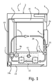
Figure 1 is a partial and schematic cross section of a laundry-drier machine according to the invention. - Reference to "an embodiment" or "one embodiment" in the context of the present description is intended to indicate that a particular configuration, structure, or characteristic described in relation to the embodiment is comprised in at least one embodiment. Hence, phrases such as "in an embodiment" or "in one embodiment" and the like, that may be present in various points of the present description, do not necessarily all refer to one and the same embodiment. Moreover, the particular configurations, structures, or characteristics can be combined in any adequate way in one or more embodiments. The references used in what follows are merely provided for convenience and do not define the sphere of protection or the scope of the embodiments.
- It is moreover pointed out that in the sequel of the present description only the elements useful for an understanding of the invention will be described in particular detail, taking for granted that the machine forming the subject of the invention comprises all the other elements in themselves known for normal operation of a laundry-drier machine.
- With particular reference to
Figure 1 , designated as a whole by 1 is a laundry-drier machine according to the present invention. In the case illustrated, themachine 1 is a drier machine, namely, a machine designed to perform only drying functions, of the condensation type. - The
machine 1 has a load-bearing structure orcabinet 2, rotatably mounted within which is adrum 3, designed for containing the laundry. Thedrum 3 has a generally cylindrical shape and is mounted for rotating about a substantially horizontal axis of rotation. Provided within thecabinet 2 are means, of a type in itself known, for rotatably supporting thedrum 3, which can, for example, be of a rolling type, such as wheels or rollers, or of a sliding type, such as runners. - The
cabinet 2 has a front face, comprising afront wall 2a, having an opening - not indicated - on which adoor 4 is mounted for enabling access to the inside of thedrum 3. In the front face of thecabinet 2, in particular in its upper region, a control panel or user interface of the machine is provided, designated as a whole by 5. Thepanel 5 forms part of a control system of the machine, which includes acontrol unit 6, preferably of an electronic microcontroller type, pre-arranged for controlling execution of a plurality of operating programs of the machine. - The
panel 5 can comprise at least one ON/OFF button, means for selection and start of one from a plurality of operating programs, means for selection of parameters of the operating programs that can be set by the user, and, preferably, display means. The aforesaid selection and starting means comprise, for example, a rotary selector with a number of positions and a program start button, but for the purpose other means of a type in itself known in the sector can obviously be used. Also the means for the selection of optional program parameters can include a selector and/or keys. The display means can comprise a display or warning lights. - The
machine 1 comprises ventilation means, designed for generating a forced flow of air, and heating means, designed for heating the air of the forced flow, and motor means designed to bring about rotation of thedrum 3 in a range of speeds, for example comprised between 0 r.p.m. and approximately 250 r.p.m., preferably between 0 and approximately 150 r.p.m. - In the example of embodiment illustrated, the ventilation means include a substantially closed path for the air (not indicated), defined in a known way within the
cabinet 2, and possibly comprising a hollow part of thedoor 4. The aforesaid path substantially extends between an opening of the front wall of thedrum 3 and at least one opening of the rear wall of thedrum 3. InFigure 1 , the white arrows (one of which is designated by F) indicate the forced flow along the aforesaid path and through thedrum 3. The ventilation means further comprise a fan 7 that is operative along the aforesaid path and that can be driven, at a controllable speed, by thesame motor 8 that is to bring about rotation of thedrum 3, with the aid of a suitable transmission, here represented by abelt 8a. In a variant embodiment, not represented, the fan 7 is provided with a motor of its own. - Along the path for the air a filter 9 is provided of conception and operation in themselves known, which can be inspected by the user of the
machine 1 and is designed to retain the fluff released into the forced flow F by the garments being treated. - In the embodiment exemplified, the means for heating the air include a
heat pump 10, which operates along the path for the air and comprises afirst heat exchanger 11, asecond heat exchanger 12, and acompressor 13, which is operatively set between the twoheat exchangers heat pump 10 can possibly include a respective filter for the air, not illustrated, accessible by the user. - It should be noted that the use of a heat pump for heating the drying air is to be understood as envisaged merely by way of example. In said perspective, in fact, the
heat pump 10 can be replaced by one or more traditional electrical resistances, for example positioned in the ventilation circuit downstream of the fan 7 and upstream of thedrum 3. In an embodiment of this sort, in the case of condensation drier machine, in the ventilation circuit, preferably upstream of the fan, a known device for condensation of the air will be provided (for example, substantially in the position occupied inFigure 1 by the heat pump 10). - Once again with reference to the non-limiting example of
Figure 1 , designated by 14 is a tray for collecting the water produced by condensation of the moisture present in the air of the forced flow F at output from thedrum 3. In the example, associated to thetray 14 is apump 14a, which, via aduct 15, takes the condensation water from thetray 14 to aremovable container 16, positioned in the top part of themachine 1. To thecontainer 16 there can be associated an overflow duct, not represented, in communication with thetray 14 itself. - The drying programs that can be selected via the selection means of the
user interface 5 comprise treatment programs that terminate when at least one condition arises, which can be detected by the control system of the machine. As per the known art, the condition or conditions that determine the end of one of said programs can comprise program time and/or temperature of the air of the forced flow and/or rate of moisture of the items of laundry. - The rate of moisture of the load of laundry can be measured, for example, according to the criteria taught by the Italian norm CEI EN 61121 Ed.2 2007-10, according to which the value of moisture of the load identifies the amount of water contained in weight percentage of the dry load, according to the formula:
- moisture = (weight of moist load - weight of dry load) / weight of dry load where the weight of the dry load can be determined according to a procedure described in the aforesaid norm.
- The control logic of the
machine 1 detects, in the course execution of a drying program, via sensor means described hereinafter, data representing a value of moisture and compares them with reference data contained in the control logic. The aforesaid reference data, which also represent values of moisture, are obtained following upon experimental characterization tests, conducted in standardized conditions in order to associate said reference data to a rate of moisture. The aforesaid reference data can be organized in the control logic with modalities in themselves known in the sector, for example, in tabular form or using fuzzy-logic techniques. - Expiry of the program time can be easily measured by the
control unit 6, the microcontroller of which is equipped with an internal clock of its own, whilst the temperature of the air and the moisture of the garments can be detected by theunit 6 via purposely provided sensor means, of a type in itself known. In the example ofFigure 1 , the temperature of the air is detected via a sensor 25 (for example, of an NTC type) positioned in the ventilation circuit immediately downstream of thedrum 3, whilst the moisture of the items of laundry is detected by means of a sensor 26 (for example, a conductivity sensor), which operates directly inside the drum, so as to come into contact with the load. - For use of the machine, the user can set the garment or garments to be dried in the
drum 3 and close thedoor 4. After turning on themachine 1, the user can select the treatment program and the possible settable options associated thereto (for example, a value of residual moisture desired for the load at the end of the treatment cycle) and then start execution of the program itself. Thecontrol unit 6 thus governs start of the drying step, in the course of which themotor 8, the fan 7, and theheat pump 10 are activated. The program proceeds with modalities in themselves known: for example, themotor 8 is controlled so as to produce a rotation of the drum at a first speed of between 30 and 60 r.p.m. and the heat pump is controlled, with the aid of thesensor 25, to obtain a heating of the drying air to a temperature of between 55 and 65°C. This part of the drying step may possibly comprise pauses in the rotation of the drum, or substeps of slower rotation of the drum, or reversal of rotation of the drum, according to techniques in themselves known. - The load of the
drum 3 is then progressively dried and de-humidified. In the course of the drying step thecontrol unit 6 monitors not only the temperature of the air of the forced flow F, by means of thesensor 25, but also the moisture of the load, by means of thesensor 26. - The drying step comprises at least one substep during which the
drum 3 is brought to assume a second speed of rotation, higher than the first speed. The increase in speed is governed by thecontrol unit 6, which controls in an appropriate way the adjustable-speed motor 8. The aforesaid second speed is in particular equal to or higher than the minimum speed that enables the laundry to be kept adherent to the walls of thedrum 3. Typically, the second speed is comprised between 80 and 240 r.p.m., since the diameter of the drum ranges between 45 and 65 cm. In a preferred embodiment, the second speed is comprised between approximately 80 and approximately 120 r.p.m.. - According to the invention, the aforesaid substep at the second speed - hereinafter referred to as "satellization substep" - is started by the
control unit 6 when the latter detects, by means of thesensor 26, that the value of moisture of the load of laundry is equal to or lower than a first predetermined moisture threshold (as has been said, thesensor 26 detects data representing the value of moisture). Thecontrol system 6 contains information representing the threshold value; i.e., said value is stored in the control unit or is obtained by the control unit on the basis of data or algorithms stored therein. The aforesaid threshold value represents a value of moisture of the load preferably comprised between approximately 5% and 15%, even more preferably between approximately 8% and 10%. In the course of the satellization substep the ventilation means 7 and heating means 10 are kept active. - The invention is based upon the perception of the fact that the release of fluff by the garments being treated, into the forced flow of air, starts or is higher precisely when the moisture of the garments being treated is relatively low, or drops below of a certain level, as has been said roughly comprised between 5% and 15%. In practice, the moisture of the garments acts as a "cushion" and protects the garment from the action of rubbing against the peripheral wall of the drum, which generates release of fluff. However, as the drying process proceeds, the moisture of the garments is reduced, thus rendering progressively less effective this protective effect of the garment in regard to release of fluff.
- The satellization substep hence envisages a second speed of rotation equal to or slightly higher than the minimum speed that enables the laundry to be kept adherent to the walls of the
drum 3, so as to minimize the stresses on the garments, preventing damage and wear thereof: the garments are safeguarded, given that rubbing thereof on the drum is prevented in a period in which, since the garments are almost dry, they are more subject to getting wear and generation of fluff. - The satellization substep has a relatively long duration, as compared with the similar substeps envisaged in
EP 0 404 047 , and in any case preferably not shorter than approximately 5 minutes. - In one embodiment of the invention, the satellization substep proceeds, with the
drum 3 kept in rotation at the aforesaid second speed, up to the end of the drying step. In effect, in this case, the end of the satellization substep coincides with the end of the drying step. Albeit less advantageous, it is, however, possible to envisage that the drying step proceeds beyond the satellization substep, for example, with a substep in which the drum is brought back to the first speed. - Preferably, the drying step, or the satellization substep, terminates when a condition is reached that can be detected by the control system of the
machine 1. - In one embodiment, the aforesaid condition comprises reaching of a value of moisture of the load of laundry that is equal to or lower than a second predetermined threshold, which is lower than the first threshold. Consequently, when the
control unit 6 detects, via thesensor 26, to the moisture of the load has dropped below the aforesaid second threshold, the drying step (or the satellization substep) terminates. For this purpose, thecontrol system 6 contains information representing the value of the second threshold; i.e., said value is stored in the control unit or is obtained by the control unit on the basis of data or algorithms stored therein. For example, in one embodiment, the value of the second threshold is determined by the user in an indirect way, following upon selection, using the user-interface means 5, of a parameter corresponding to the desired value of moisture of the load at the end of the program (i.e., at the end of the treatment cycle). Also the second threshold may, however, be predetermined. The value of the second threshold preferably represents a value of moisture of the load roughly comprised between approximately -3% and approximately 12%. - In another embodiment, the condition that causes the end of the drying step, or of the satellization substep, is expiry of a given period of time. Said period of time can be measured by the
control unit 6 and can be, for example, measured starting from start of the drying program or from start of the satellization substep. In one embodiment, the aforesaid period of time may be variable, in particular determined as a function of the weight of the load of laundry. For this purpose, in one embodiment, themachine 1 is provided with means for detecting or estimating the load of laundry, of a conception in itself known. In one embodiment, for example, the weight of the load of laundry is estimated according to the temperature of the air of the forced flow F leaving thedrum 3, which can be detected via thesensor 25. In an embodiment of this sort, thecontrol unit 6 monitors the variation in time of the temperature of the air of the forced flow F, during an initial period of the drying step, by means of algorithms based upon the criterion whereby the higher the load, the lower the temperature gradient. - Irrespective of the methodology used to determine the end of the drying step or the satellization substep, the
control unit 6 de-activates theheat pump 10, and possibly de-activates also the fan 7 and themotor 8, for example when to the end of the drying step there corresponds the end of the treatment program. In the case where the program envisages a final step of cooling of the garments, operation of just theheat pump 10 can be interrupted, keeping, instead, active the fan 7 and themotor 8, with the latter for example brought back to the first speed (30-60 r.p.m.). Possibly, between the end of the drying step and the start of the cooling step a pause, or a step of slow rotation of thedrum 3 may be envisaged. - In the possible cooling step that follows the drying step the air of the forced flow F is passed in the
drum 3 without being heated, with thedrum 3 in rotation. In one embodiment, also in at least one part of the cooling step, thedrum 3 is brought to assume the aforesaid second speed of rotation in order to carry out a satellization of the load. In this case, start of a satellization substep is preferably independent of the moisture of the garments and can be started either at the start of the cooling step itself or else after a pre-determined time following starting thereof. - From the description provided, the characteristics of the present invention emerge clearly, as likewise its advantages.
- The process and machine according to the invention afford extremely satisfactory drying results, with a production of fluff by the garments that is reduced as compared to known solutions. The air filter or filters envisaged in the ventilation circuit hence more get clogged slowly, to the advantage of the user and of the efficiency of the treatment cycle. The need for maintenance and cleaning of the filters is reduced.
- The solution according to the invention hence enables a greater care for the garments being treated, reducing rubbing thereof on the drum. The solution according to the invention is advantageous for multiple types of fabric, whether these be fabrics that are relatively far from delicate, such as cotton or towelling, or delicate fabrics, such as wool and the like. The drying methodology proposed is particularly advantageous also for dark-coloured garments, for which the production of fluff is associated to loss of colour.
- It is clear that numerous variations may be made by the person skilled in the art to the laundry-drier machine described by way example, without thereby departing from the scope of the invention as defined in the annexed claims.
- In the preferred embodiments previously exemplified, the drying step envisages a continuous satellization substep, i.e., with the drum kept at the second speed up to the end of the substep. In possible variant embodiments, the substep can be divided into at least two parts, interspersed by reversal of the direction of rotation and/or short pauses of rotation and/or short periods of rotation of the drum at speeds different from the second speed (for example at the first speed or at even slower speeds), where by "short period" is meant a time roughly of between 5 and 15 seconds.
- The invention may, of course, be applied also to machines for washing and drying laundry, by introducing arrangements that are evident for the person skilled in the art, taking into account that in this case the laundry drum turns inside a tank.
Claims (15)
- A process for drying laundry in a machine for drying laundry (1), the process comprising execution of a drying phase during which air of a forced flow (F) is heated and made to pass through a rotating drum (3) containing a laundry load, wherein the drying phase comprises at least one sub-phase during which the drum (3) is brought to take on a determined rotation speed, which is equal to, or higher than, the lowest speed allowing to hold the laundry adhering to a wall of the drum (3), the process being characterized by comprising the steps of:- detecting, during the drying phase, a value of moisture of the laundry load, and- starting the said sub-phase when the detected value of moisture is equal to, or lower than, a first determined threshold.
- The process according to claim 1, wherein the said sub-phase lasts substantially not less than 5 minutes.
- The process according to claim 1 or 2, wherein at least one of the drying phase and the said sub-phase ends upon achievement of a condition which is detectable by a control system (5, 6, 25, 26) of the machine (1).
- The process according to claim 3, wherein the said sub-phase continues, with the drum (3) kept in rotation at the said determined speed, until ending of the drying phase.
- The process according to one of preceding claims, wherein during the said sub-phase at least one reversal of the direction of rotation of the drum (3) and/or a short pause in the rotation of the drum (3) and/or a short period of rotation of the drum (3) at a speed which is different from the said determined speed is provided for.
- The process according to claim 3, wherein the said condition comprises at least one of- achievement of a value of dampness of the laundry load which is equal to, or lower than, a second determined threshold, which is lower than the first threshold,- expiration of a determined period of time.
- The process according to claim 6, wherein the said period of time is determined as a function of the weight of the laundry load.
- The process according to claim 6, wherein the second threshold is determined as a function of a parameter selectable by a user of the machine (1).
- The process according to any one of the preceding claims, further comprising a cooling phase of the laundry load which follows the drying phase, wherein during the cooling phase air of the forced flow (F) is made to pass through the drum (3) without being heated, with the drum (3) set in rotation (3), where in particular for at least one part of the cooling phase the drum (3) is brought to take on the said determined rotation speed.
- The process according to any one of the preceding claims, wherein said determined rotation speed is substantially comprised between 80 and 240 rpm, preferably between about 80 and 120 rpm.
- The process according to any one of the preceding claims, wherein said first threshold is representative of a value of dampness of the laundry load comprised between 5% and 15%.
- The process according to any one of the preceding claims, wherein said second threshold is representative of a value of dampness of the laundry load comprised between -3% and 12%.
- A machine for drying laundry, having a cabinet (2) within which a rotatable laundry drum (3) is housed, the machine (1) having ventilation means (7), adapted to generate a forced flow of air (F), heating means (10), adapted to heat air of the forced flow (F), motor means (8, 8a), adapted to cause rotation of the drum (3), a control system (5, 6, 25, 26) prearranged for controlling execution of at least one operating program which comprises one drying phase, during which air of the forced flow (F) is heated and made to pass through the drum (3), wherein the drying phase includes at least one sub-phase during which the drum (3) is brought to take on a determined rotation speed, which is equal to, or greater than, the lowest speed allowing to hold the laundry adhering to a wall of the drum (3), characterized in that- the control system (5, 6, 25, 26) comprises sensor means (26) for detecting, during the drying phase, values of moisture of the laundry load contained in the drum (3),- the control system (5, 6, 25, 26) contains information which is representative of a first moisture threshold value, and- the control system (5, 6, 25, 26) is prearranged for starting the said sub-phase when a detected value of moisture is equal to, or lower than, the said first threshold value.
- The machine according to claim 13, wherein the control system (5, 6, 25, 26) is prearranged for controlling continuation of the said sub-phase, with the drum (3) kept at the determined speed, until achievement of a condition which is detectable by the control system (5, 6, 25, 26).
- The machine according to claim 13, wherein- the control system (5, 6, 25, 26) contains information representative of a second moisture threshold value, lower than the first moisture threshold value, and wherein the control system (5, 6, 25, 26) is prearranged for stopping the said sub-phase when a detected value of moisture is equal to, or lower than, the second threshold value, or- the control system (5, 6, 25, 26) is prearranged for stopping the said sub-phase upon expiration of a determined period of time, the control system (5, 6, 25, 26) comprising in particular means for estimating the weight of the laundry load and being prearranged for determining the said period of time as a function of the weight of the laundry load.
Applications Claiming Priority (1)
| Application Number | Priority Date | Filing Date | Title |
|---|---|---|---|
| IT001070A ITTO20101070A1 (en) | 2010-12-27 | 2010-12-27 | PROCEDURE AND MACHINE FOR THE LINEN DRYING |
Publications (2)
| Publication Number | Publication Date |
|---|---|
| EP2468950A1 true EP2468950A1 (en) | 2012-06-27 |
| EP2468950B1 EP2468950B1 (en) | 2016-04-27 |
Family
ID=43737458
Family Applications (1)
| Application Number | Title | Priority Date | Filing Date |
|---|---|---|---|
| EP11195381.6A Active EP2468950B1 (en) | 2010-12-27 | 2011-12-22 | Process and machine for drying laundry |
Country Status (3)
| Country | Link |
|---|---|
| EP (1) | EP2468950B1 (en) |
| IT (1) | ITTO20101070A1 (en) |
| PL (1) | PL2468950T3 (en) |
Cited By (7)
| Publication number | Priority date | Publication date | Assignee | Title |
|---|---|---|---|---|
| EP2770102A1 (en) | 2013-02-25 | 2014-08-27 | Fagor, S. Coop. | Method for drying laundry contained in a laundry dryer and a laundry dryer implementing said method |
| US20140277751A1 (en) * | 2013-03-15 | 2014-09-18 | Whirlpool Corporation | Methods and compositions for treating laundry items |
| EP2789728A1 (en) | 2013-04-08 | 2014-10-15 | Electrolux Appliances Aktiebolag | Method for controlling a motor of a laundry dryer |
| ITTO20130586A1 (en) * | 2013-07-12 | 2015-01-13 | Indesit Co Spa | METHOD OF CONTROL OF A DOMESTIC EQUIPMENT SUITABLE FOR PERFORMING AT LEAST ONE CYCLE OF DRYING OF LINEN, AND DOMESTIC EQUIPMENT OPERATING ACCORDING TO THESE METHOD OF CONTROL |
| ITPR20130100A1 (en) * | 2013-12-04 | 2015-06-05 | Indesit Co Spa | CLOTHING DRYING METHOD. |
| US9702074B2 (en) | 2013-03-15 | 2017-07-11 | Whirlpool Corporation | Methods and compositions for treating laundry items |
| CN107675429A (en) * | 2017-10-31 | 2018-02-09 | 青岛海尔洗衣机有限公司 | The washing methods and automatic washing machine of a kind of fleece fabrics |
Citations (8)
| Publication number | Priority date | Publication date | Assignee | Title |
|---|---|---|---|---|
| DE1924961A1 (en) * | 1969-05-13 | 1970-11-26 | Siemens Elektrogeraete Gmbh | Process for drying delicate types of tissue |
| DE3017109A1 (en) * | 1980-05-03 | 1981-11-05 | Miele & Cie GmbH & Co, 4830 Gütersloh | Tumble-dry procedure for combined washing and drying machine - interrupts slow drum rotation with short-period fast rotation |
| CH659841A5 (en) * | 1982-07-26 | 1987-02-27 | V Zug Ag | Process for the drying of ready-made clothing laundry in a drum-type dryer |
| EP0404047A1 (en) | 1989-06-23 | 1990-12-27 | Vota, Roberto | A process and a machine for washing and drying textile articles |
| EP0684335A1 (en) * | 1994-05-26 | 1995-11-29 | Merloni Elettrodomestici S.p.A. | Method for drying laundry and machine implementing such method |
| US20050044639A1 (en) * | 2003-08-26 | 2005-03-03 | Kwang Soo Kim | Method of controlling drying cycle in washing machine |
| EP1577433A2 (en) * | 2004-02-17 | 2005-09-21 | LG Electronics Inc. | Structure for supplying hot air for drying clothes in drum type washing machine and operation control method thereof |
| EP2014822A1 (en) * | 2007-07-13 | 2009-01-14 | Electrolux Home Products Corporation N.V. | Control method for controlling a tumble laundry drier for drying wool laundry |
-
2010
- 2010-12-27 IT IT001070A patent/ITTO20101070A1/en unknown
-
2011
- 2011-12-22 EP EP11195381.6A patent/EP2468950B1/en active Active
- 2011-12-22 PL PL11195381.6T patent/PL2468950T3/en unknown
Patent Citations (8)
| Publication number | Priority date | Publication date | Assignee | Title |
|---|---|---|---|---|
| DE1924961A1 (en) * | 1969-05-13 | 1970-11-26 | Siemens Elektrogeraete Gmbh | Process for drying delicate types of tissue |
| DE3017109A1 (en) * | 1980-05-03 | 1981-11-05 | Miele & Cie GmbH & Co, 4830 Gütersloh | Tumble-dry procedure for combined washing and drying machine - interrupts slow drum rotation with short-period fast rotation |
| CH659841A5 (en) * | 1982-07-26 | 1987-02-27 | V Zug Ag | Process for the drying of ready-made clothing laundry in a drum-type dryer |
| EP0404047A1 (en) | 1989-06-23 | 1990-12-27 | Vota, Roberto | A process and a machine for washing and drying textile articles |
| EP0684335A1 (en) * | 1994-05-26 | 1995-11-29 | Merloni Elettrodomestici S.p.A. | Method for drying laundry and machine implementing such method |
| US20050044639A1 (en) * | 2003-08-26 | 2005-03-03 | Kwang Soo Kim | Method of controlling drying cycle in washing machine |
| EP1577433A2 (en) * | 2004-02-17 | 2005-09-21 | LG Electronics Inc. | Structure for supplying hot air for drying clothes in drum type washing machine and operation control method thereof |
| EP2014822A1 (en) * | 2007-07-13 | 2009-01-14 | Electrolux Home Products Corporation N.V. | Control method for controlling a tumble laundry drier for drying wool laundry |
Cited By (19)
| Publication number | Priority date | Publication date | Assignee | Title |
|---|---|---|---|---|
| EP2770102A1 (en) | 2013-02-25 | 2014-08-27 | Fagor, S. Coop. | Method for drying laundry contained in a laundry dryer and a laundry dryer implementing said method |
| US9758914B2 (en) | 2013-03-15 | 2017-09-12 | Whirlpool Corporation | Methods and compositions for treating laundry items |
| US10011935B2 (en) | 2013-03-15 | 2018-07-03 | Whirlpool Corporation | Methods and compositions for treating laundry items |
| US9689101B2 (en) | 2013-03-15 | 2017-06-27 | Whirlpool Corporation | Methods and compositions for treating laundry items |
| US9702074B2 (en) | 2013-03-15 | 2017-07-11 | Whirlpool Corporation | Methods and compositions for treating laundry items |
| US10266981B2 (en) | 2013-03-15 | 2019-04-23 | Whirlpool Corporation | Methods and compositions for treating laundry items |
| US9631310B2 (en) | 2013-03-15 | 2017-04-25 | Whirlpool Corporation | Methods and compositions for treating laundry items |
| US9644301B2 (en) | 2013-03-15 | 2017-05-09 | Whirlpool Corporation | Methods and compositions for treating laundry items |
| US10072373B2 (en) * | 2013-03-15 | 2018-09-11 | Whirlpool Corporation | Methods and compositions for treating laundry items |
| US10017893B2 (en) | 2013-03-15 | 2018-07-10 | Whirlpool Corporation | Methods and compositions for treating laundry items |
| US20140277751A1 (en) * | 2013-03-15 | 2014-09-18 | Whirlpool Corporation | Methods and compositions for treating laundry items |
| US9677218B2 (en) | 2013-04-08 | 2017-06-13 | Electrolux Appliances Aktiebolag | Method for controlling a motor of a laundry dryer |
| EP2789728A1 (en) | 2013-04-08 | 2014-10-15 | Electrolux Appliances Aktiebolag | Method for controlling a motor of a laundry dryer |
| ITTO20130586A1 (en) * | 2013-07-12 | 2015-01-13 | Indesit Co Spa | METHOD OF CONTROL OF A DOMESTIC EQUIPMENT SUITABLE FOR PERFORMING AT LEAST ONE CYCLE OF DRYING OF LINEN, AND DOMESTIC EQUIPMENT OPERATING ACCORDING TO THESE METHOD OF CONTROL |
| WO2015004611A1 (en) * | 2013-07-12 | 2015-01-15 | Indesit Company S.P.A. | Method for controlling a household appliance adapted to carry out at least one laundry drying cycle, and household appliance operating according to said controlling method |
| WO2015083062A1 (en) * | 2013-12-04 | 2015-06-11 | Indesit Company S.P.A. | Method for drying laundry |
| ITPR20130100A1 (en) * | 2013-12-04 | 2015-06-05 | Indesit Co Spa | CLOTHING DRYING METHOD. |
| CN107675429A (en) * | 2017-10-31 | 2018-02-09 | 青岛海尔洗衣机有限公司 | The washing methods and automatic washing machine of a kind of fleece fabrics |
| CN107675429B (en) * | 2017-10-31 | 2022-07-08 | 天津海尔洗涤电器有限公司 | Washing method of cashmere fabric and full-automatic washing machine |
Also Published As
| Publication number | Publication date |
|---|---|
| EP2468950B1 (en) | 2016-04-27 |
| PL2468950T3 (en) | 2016-10-31 |
| ITTO20101070A1 (en) | 2012-06-28 |
Similar Documents
| Publication | Publication Date | Title |
|---|---|---|
| EP2468950B1 (en) | Process and machine for drying laundry | |
| US20200240064A1 (en) | Controlled moisture removal in a laundry treating appliance | |
| US8997377B2 (en) | Clothes treatment apparatus and method for controlling a clothes treatment apparatus | |
| US9279213B2 (en) | Laundry treating appliance with imaging control | |
| EP2636788B1 (en) | Clothes dryer and washer/dryer | |
| EP3124680B1 (en) | Method for adapting operation parameters during drying in a heat pump dryer | |
| EP3252211B1 (en) | Method for controlling a heat pump laundry drying machine | |
| EP3425107B1 (en) | Method for controlling a heat pump laundry drying machine | |
| EP2960364B1 (en) | Laundry drying apparatus and method of controlling a drying cycle in a laundry drying apparatus | |
| EP0829569A2 (en) | Washer-dryer apparatus | |
| EP3124689A1 (en) | Method of operating a heat-pump dryer | |
| JPH10127979A (en) | Drum type drying and washing machine | |
| CN109312516A (en) | For operating the method and laundry treatment appliance of laundry treatment appliance | |
| EP3124690A1 (en) | Method of operating a heat-pump dryer | |
| EP2503048B1 (en) | Method for washing laundry in a laundry washing machine and laundry washing machine | |
| JPH0326292A (en) | Drum type washing and drying machine | |
| JP6716675B2 (en) | Washing and drying machine | |
| TWI660088B (en) | Washer dryer | |
| JP3807099B2 (en) | Drum type washer / dryer | |
| JP6910771B2 (en) | Clothes dryer | |
| JP3744162B2 (en) | Drum type washer / dryer | |
| JP2009072491A (en) | Drying machine and washing and drying machine | |
| JP4881825B2 (en) | Dryer and washing dryer | |
| JP2009077772A (en) | Drying machine and washing and drying machine | |
| KR20050089343A (en) | Method for controlling the drying stage of drum washing machine |
Legal Events
| Date | Code | Title | Description |
|---|---|---|---|
| AK | Designated contracting states |
Kind code of ref document: A1 Designated state(s): AL AT BE BG CH CY CZ DE DK EE ES FI FR GB GR HR HU IE IS IT LI LT LU LV MC MK MT NL NO PL PT RO RS SE SI SK SM TR |
|
| AX | Request for extension of the european patent |
Extension state: BA ME |
|
| PUAI | Public reference made under article 153(3) epc to a published international application that has entered the european phase |
Free format text: ORIGINAL CODE: 0009012 |
|
| 17P | Request for examination filed |
Effective date: 20121221 |
|
| 17Q | First examination report despatched |
Effective date: 20150928 |
|
| GRAP | Despatch of communication of intention to grant a patent |
Free format text: ORIGINAL CODE: EPIDOSNIGR1 |
|
| GRAS | Grant fee paid |
Free format text: ORIGINAL CODE: EPIDOSNIGR3 |
|
| INTG | Intention to grant announced |
Effective date: 20160216 |
|
| GRAA | (expected) grant |
Free format text: ORIGINAL CODE: 0009210 |
|
| AK | Designated contracting states |
Kind code of ref document: B1 Designated state(s): AL AT BE BG CH CY CZ DE DK EE ES FI FR GB GR HR HU IE IS IT LI LT LU LV MC MK MT NL NO PL PT RO RS SE SI SK SM TR |
|
| REG | Reference to a national code |
Ref country code: GB Ref legal event code: FG4D |
|
| REG | Reference to a national code |
Ref country code: CH Ref legal event code: EP |
|
| REG | Reference to a national code |
Ref country code: AT Ref legal event code: REF Ref document number: 794948 Country of ref document: AT Kind code of ref document: T Effective date: 20160515 |
|
| REG | Reference to a national code |
Ref country code: IE Ref legal event code: FG4D |
|
| REG | Reference to a national code |
Ref country code: DE Ref legal event code: R096 Ref document number: 602011025881 Country of ref document: DE |
|
| REG | Reference to a national code |
Ref country code: LT Ref legal event code: MG4D |
|
| REG | Reference to a national code |
Ref country code: NL Ref legal event code: MP Effective date: 20160427 |
|
| REG | Reference to a national code |
Ref country code: AT Ref legal event code: MK05 Ref document number: 794948 Country of ref document: AT Kind code of ref document: T Effective date: 20160427 |
|
| PG25 | Lapsed in a contracting state [announced via postgrant information from national office to epo] |
Ref country code: NL Free format text: LAPSE BECAUSE OF FAILURE TO SUBMIT A TRANSLATION OF THE DESCRIPTION OR TO PAY THE FEE WITHIN THE PRESCRIBED TIME-LIMIT Effective date: 20160427 |
|
| PG25 | Lapsed in a contracting state [announced via postgrant information from national office to epo] |
Ref country code: LT Free format text: LAPSE BECAUSE OF FAILURE TO SUBMIT A TRANSLATION OF THE DESCRIPTION OR TO PAY THE FEE WITHIN THE PRESCRIBED TIME-LIMIT Effective date: 20160427 Ref country code: FI Free format text: LAPSE BECAUSE OF FAILURE TO SUBMIT A TRANSLATION OF THE DESCRIPTION OR TO PAY THE FEE WITHIN THE PRESCRIBED TIME-LIMIT Effective date: 20160427 Ref country code: NO Free format text: LAPSE BECAUSE OF FAILURE TO SUBMIT A TRANSLATION OF THE DESCRIPTION OR TO PAY THE FEE WITHIN THE PRESCRIBED TIME-LIMIT Effective date: 20160727 |
|
| REG | Reference to a national code |
Ref country code: FR Ref legal event code: PLFP Year of fee payment: 6 |
|
| PG25 | Lapsed in a contracting state [announced via postgrant information from national office to epo] |
Ref country code: GR Free format text: LAPSE BECAUSE OF FAILURE TO SUBMIT A TRANSLATION OF THE DESCRIPTION OR TO PAY THE FEE WITHIN THE PRESCRIBED TIME-LIMIT Effective date: 20160728 Ref country code: PT Free format text: LAPSE BECAUSE OF FAILURE TO SUBMIT A TRANSLATION OF THE DESCRIPTION OR TO PAY THE FEE WITHIN THE PRESCRIBED TIME-LIMIT Effective date: 20160829 Ref country code: RS Free format text: LAPSE BECAUSE OF FAILURE TO SUBMIT A TRANSLATION OF THE DESCRIPTION OR TO PAY THE FEE WITHIN THE PRESCRIBED TIME-LIMIT Effective date: 20160427 Ref country code: ES Free format text: LAPSE BECAUSE OF FAILURE TO SUBMIT A TRANSLATION OF THE DESCRIPTION OR TO PAY THE FEE WITHIN THE PRESCRIBED TIME-LIMIT Effective date: 20160427 Ref country code: HR Free format text: LAPSE BECAUSE OF FAILURE TO SUBMIT A TRANSLATION OF THE DESCRIPTION OR TO PAY THE FEE WITHIN THE PRESCRIBED TIME-LIMIT Effective date: 20160427 Ref country code: SE Free format text: LAPSE BECAUSE OF FAILURE TO SUBMIT A TRANSLATION OF THE DESCRIPTION OR TO PAY THE FEE WITHIN THE PRESCRIBED TIME-LIMIT Effective date: 20160427 Ref country code: LV Free format text: LAPSE BECAUSE OF FAILURE TO SUBMIT A TRANSLATION OF THE DESCRIPTION OR TO PAY THE FEE WITHIN THE PRESCRIBED TIME-LIMIT Effective date: 20160427 Ref country code: AT Free format text: LAPSE BECAUSE OF FAILURE TO SUBMIT A TRANSLATION OF THE DESCRIPTION OR TO PAY THE FEE WITHIN THE PRESCRIBED TIME-LIMIT Effective date: 20160427 |
|
| PG25 | Lapsed in a contracting state [announced via postgrant information from national office to epo] |
Ref country code: BE Free format text: LAPSE BECAUSE OF FAILURE TO SUBMIT A TRANSLATION OF THE DESCRIPTION OR TO PAY THE FEE WITHIN THE PRESCRIBED TIME-LIMIT Effective date: 20160427 |
|
| REG | Reference to a national code |
Ref country code: DE Ref legal event code: R097 Ref document number: 602011025881 Country of ref document: DE |
|
| PG25 | Lapsed in a contracting state [announced via postgrant information from national office to epo] |
Ref country code: RO Free format text: LAPSE BECAUSE OF FAILURE TO SUBMIT A TRANSLATION OF THE DESCRIPTION OR TO PAY THE FEE WITHIN THE PRESCRIBED TIME-LIMIT Effective date: 20160427 Ref country code: DK Free format text: LAPSE BECAUSE OF FAILURE TO SUBMIT A TRANSLATION OF THE DESCRIPTION OR TO PAY THE FEE WITHIN THE PRESCRIBED TIME-LIMIT Effective date: 20160427 Ref country code: SK Free format text: LAPSE BECAUSE OF FAILURE TO SUBMIT A TRANSLATION OF THE DESCRIPTION OR TO PAY THE FEE WITHIN THE PRESCRIBED TIME-LIMIT Effective date: 20160427 Ref country code: CZ Free format text: LAPSE BECAUSE OF FAILURE TO SUBMIT A TRANSLATION OF THE DESCRIPTION OR TO PAY THE FEE WITHIN THE PRESCRIBED TIME-LIMIT Effective date: 20160427 Ref country code: EE Free format text: LAPSE BECAUSE OF FAILURE TO SUBMIT A TRANSLATION OF THE DESCRIPTION OR TO PAY THE FEE WITHIN THE PRESCRIBED TIME-LIMIT Effective date: 20160427 |
|
| RAP2 | Party data changed (patent owner data changed or rights of a patent transferred) |
Owner name: WHIRLPOOL EMEA S.P.A |
|
| PG25 | Lapsed in a contracting state [announced via postgrant information from national office to epo] |
Ref country code: SM Free format text: LAPSE BECAUSE OF FAILURE TO SUBMIT A TRANSLATION OF THE DESCRIPTION OR TO PAY THE FEE WITHIN THE PRESCRIBED TIME-LIMIT Effective date: 20160427 |
|
| PLBE | No opposition filed within time limit |
Free format text: ORIGINAL CODE: 0009261 |
|
| STAA | Information on the status of an ep patent application or granted ep patent |
Free format text: STATUS: NO OPPOSITION FILED WITHIN TIME LIMIT |
|
| 26N | No opposition filed |
Effective date: 20170130 |
|
| PG25 | Lapsed in a contracting state [announced via postgrant information from national office to epo] |
Ref country code: SI Free format text: LAPSE BECAUSE OF FAILURE TO SUBMIT A TRANSLATION OF THE DESCRIPTION OR TO PAY THE FEE WITHIN THE PRESCRIBED TIME-LIMIT Effective date: 20160427 |
|
| REG | Reference to a national code |
Ref country code: CH Ref legal event code: PL |
|
| PG25 | Lapsed in a contracting state [announced via postgrant information from national office to epo] |
Ref country code: MC Free format text: LAPSE BECAUSE OF FAILURE TO SUBMIT A TRANSLATION OF THE DESCRIPTION OR TO PAY THE FEE WITHIN THE PRESCRIBED TIME-LIMIT Effective date: 20160427 |
|
| REG | Reference to a national code |
Ref country code: IE Ref legal event code: MM4A |
|
| PG25 | Lapsed in a contracting state [announced via postgrant information from national office to epo] |
Ref country code: LU Free format text: LAPSE BECAUSE OF NON-PAYMENT OF DUE FEES Effective date: 20161222 Ref country code: CH Free format text: LAPSE BECAUSE OF NON-PAYMENT OF DUE FEES Effective date: 20161231 Ref country code: LI Free format text: LAPSE BECAUSE OF NON-PAYMENT OF DUE FEES Effective date: 20161231 |
|
| REG | Reference to a national code |
Ref country code: FR Ref legal event code: PLFP Year of fee payment: 7 |
|
| PG25 | Lapsed in a contracting state [announced via postgrant information from national office to epo] |
Ref country code: IE Free format text: LAPSE BECAUSE OF NON-PAYMENT OF DUE FEES Effective date: 20161222 |
|
| PGFP | Annual fee paid to national office [announced via postgrant information from national office to epo] |
Ref country code: PL Payment date: 20171003 Year of fee payment: 7 |
|
| PG25 | Lapsed in a contracting state [announced via postgrant information from national office to epo] |
Ref country code: CY Free format text: LAPSE BECAUSE OF FAILURE TO SUBMIT A TRANSLATION OF THE DESCRIPTION OR TO PAY THE FEE WITHIN THE PRESCRIBED TIME-LIMIT Effective date: 20160427 Ref country code: HU Free format text: LAPSE BECAUSE OF FAILURE TO SUBMIT A TRANSLATION OF THE DESCRIPTION OR TO PAY THE FEE WITHIN THE PRESCRIBED TIME-LIMIT; INVALID AB INITIO Effective date: 20111222 |
|
| PG25 | Lapsed in a contracting state [announced via postgrant information from national office to epo] |
Ref country code: TR Free format text: LAPSE BECAUSE OF FAILURE TO SUBMIT A TRANSLATION OF THE DESCRIPTION OR TO PAY THE FEE WITHIN THE PRESCRIBED TIME-LIMIT Effective date: 20160427 Ref country code: IS Free format text: LAPSE BECAUSE OF FAILURE TO SUBMIT A TRANSLATION OF THE DESCRIPTION OR TO PAY THE FEE WITHIN THE PRESCRIBED TIME-LIMIT Effective date: 20160427 Ref country code: MK Free format text: LAPSE BECAUSE OF FAILURE TO SUBMIT A TRANSLATION OF THE DESCRIPTION OR TO PAY THE FEE WITHIN THE PRESCRIBED TIME-LIMIT Effective date: 20160427 |
|
| PG25 | Lapsed in a contracting state [announced via postgrant information from national office to epo] |
Ref country code: BG Free format text: LAPSE BECAUSE OF FAILURE TO SUBMIT A TRANSLATION OF THE DESCRIPTION OR TO PAY THE FEE WITHIN THE PRESCRIBED TIME-LIMIT Effective date: 20160427 |
|
| PG25 | Lapsed in a contracting state [announced via postgrant information from national office to epo] |
Ref country code: MT Free format text: LAPSE BECAUSE OF NON-PAYMENT OF DUE FEES Effective date: 20161222 |
|
| PG25 | Lapsed in a contracting state [announced via postgrant information from national office to epo] |
Ref country code: AL Free format text: LAPSE BECAUSE OF FAILURE TO SUBMIT A TRANSLATION OF THE DESCRIPTION OR TO PAY THE FEE WITHIN THE PRESCRIBED TIME-LIMIT Effective date: 20160427 |
|
| REG | Reference to a national code |
Ref country code: DE Ref legal event code: R079 Ref document number: 602011025881 Country of ref document: DE Free format text: PREVIOUS MAIN CLASS: D06F0058280000 Ipc: D06F0058300000 |
|
| PG25 | Lapsed in a contracting state [announced via postgrant information from national office to epo] |
Ref country code: PL Free format text: LAPSE BECAUSE OF NON-PAYMENT OF DUE FEES Effective date: 20181222 |
|
| PGFP | Annual fee paid to national office [announced via postgrant information from national office to epo] |
Ref country code: DE Payment date: 20221025 Year of fee payment: 12 |
|
| P01 | Opt-out of the competence of the unified patent court (upc) registered |
Effective date: 20230523 |
|
| PGFP | Annual fee paid to national office [announced via postgrant information from national office to epo] |
Ref country code: GB Payment date: 20231219 Year of fee payment: 13 |
|
| REG | Reference to a national code |
Ref country code: DE Ref legal event code: R081 Ref document number: 602011025881 Country of ref document: DE Owner name: WHIRLPOOL EMEA S.R.L., IT Free format text: FORMER OWNER: INDESIT COMPANY S.P.A., FABRIANO, ANCONA, IT |
|
| PGFP | Annual fee paid to national office [announced via postgrant information from national office to epo] |
Ref country code: IT Payment date: 20231220 Year of fee payment: 13 Ref country code: FR Payment date: 20231226 Year of fee payment: 13 |