EP2468806A1 - Method for functionalizing a container and device for carrying out this method and corresponding container - Google Patents
Method for functionalizing a container and device for carrying out this method and corresponding container Download PDFInfo
- Publication number
- EP2468806A1 EP2468806A1 EP11189761A EP11189761A EP2468806A1 EP 2468806 A1 EP2468806 A1 EP 2468806A1 EP 11189761 A EP11189761 A EP 11189761A EP 11189761 A EP11189761 A EP 11189761A EP 2468806 A1 EP2468806 A1 EP 2468806A1
- Authority
- EP
- European Patent Office
- Prior art keywords
- intermediate space
- internal space
- container
- gas
- wall
- Prior art date
- Legal status (The legal status is an assumption and is not a legal conclusion. Google has not performed a legal analysis and makes no representation as to the accuracy of the status listed.)
- Granted
Links
- 238000000034 method Methods 0.000 title claims abstract description 47
- 238000011010 flushing procedure Methods 0.000 claims abstract description 59
- 239000000126 substance Substances 0.000 claims abstract description 50
- 239000011737 fluorine Substances 0.000 claims abstract description 20
- 229910052731 fluorine Inorganic materials 0.000 claims abstract description 20
- 239000004033 plastic Substances 0.000 claims abstract description 14
- 229920003023 plastic Polymers 0.000 claims abstract description 14
- ZAMOUSCENKQFHK-UHFFFAOYSA-N Chlorine atom Chemical compound [Cl] ZAMOUSCENKQFHK-UHFFFAOYSA-N 0.000 claims abstract description 6
- 239000000460 chlorine Substances 0.000 claims abstract description 6
- 229910052801 chlorine Inorganic materials 0.000 claims abstract description 6
- PXGOKWXKJXAPGV-UHFFFAOYSA-N Fluorine Chemical compound FF PXGOKWXKJXAPGV-UHFFFAOYSA-N 0.000 claims abstract 2
- 239000007789 gas Substances 0.000 claims description 95
- 238000005259 measurement Methods 0.000 claims description 19
- 238000007306 functionalization reaction Methods 0.000 claims description 14
- 239000006096 absorbing agent Substances 0.000 claims description 12
- 238000012544 monitoring process Methods 0.000 claims description 9
- 239000002253 acid Substances 0.000 abstract description 4
- 150000007513 acids Chemical class 0.000 abstract description 4
- YCKRFDGAMUMZLT-UHFFFAOYSA-N Fluorine atom Chemical compound [F] YCKRFDGAMUMZLT-UHFFFAOYSA-N 0.000 description 18
- IJGRMHOSHXDMSA-UHFFFAOYSA-N Atomic nitrogen Chemical compound N#N IJGRMHOSHXDMSA-UHFFFAOYSA-N 0.000 description 16
- 229910052757 nitrogen Inorganic materials 0.000 description 7
- 238000003682 fluorination reaction Methods 0.000 description 6
- 239000000203 mixture Substances 0.000 description 4
- 230000001105 regulatory effect Effects 0.000 description 4
- 239000011261 inert gas Substances 0.000 description 3
- 230000006378 damage Effects 0.000 description 2
- 125000004429 atom Chemical group 0.000 description 1
- 238000011109 contamination Methods 0.000 description 1
- 230000001276 controlling effect Effects 0.000 description 1
- 230000007547 defect Effects 0.000 description 1
- 230000001419 dependent effect Effects 0.000 description 1
- 230000007613 environmental effect Effects 0.000 description 1
- 125000004435 hydrogen atom Chemical group [H]* 0.000 description 1
- 230000000977 initiatory effect Effects 0.000 description 1
- 239000012495 reaction gas Substances 0.000 description 1
- 230000003068 static effect Effects 0.000 description 1
- 230000001960 triggered effect Effects 0.000 description 1
- 238000011144 upstream manufacturing Methods 0.000 description 1
Images

Classifications
-
- C—CHEMISTRY; METALLURGY
- C08—ORGANIC MACROMOLECULAR COMPOUNDS; THEIR PREPARATION OR CHEMICAL WORKING-UP; COMPOSITIONS BASED THEREON
- C08J—WORKING-UP; GENERAL PROCESSES OF COMPOUNDING; AFTER-TREATMENT NOT COVERED BY SUBCLASSES C08B, C08C, C08F, C08G or C08H
- C08J7/00—Chemical treatment or coating of shaped articles made of macromolecular substances
- C08J7/12—Chemical modification
- C08J7/126—Halogenation
Definitions
- the present invention relates to a method for functionalizing, in particular fluorinating, a plastic container.
- the method according to the invention is preferably employed for the fluorination of containers with large volumes, in particular with volumes of 1 m 3 (cubic metre) or more up to 60 m 3 or more.
- the present invention relates to a method, to a corresponding device and to a corresponding container, with which the problems known from the prior art can at least partially be overcome.
- it is an object to provide a method for functionalizing a container, with which even containers with large volumes can be functionalized reliably.
- the present invention relates to a method for functionalizing a plastic container, the container being bounded externally by a double wall which consists of an inner wall forming an internal space of the container and an outer wall surrounding the former, an intermediate space being formed between the inner wall and the outer wall, wherein a reactive gas comprising at least one of the following reactive substances:
- the method according to the invention is preferably used for fluorination, in which the reactive substance comprises fluorine.
- the reactive gas preferably consists of a mixture of fluorine and an inert gas, for example nitrogen (N 2 ).
- a flushing gas free of reactive substances is intended to mean in particular an inert gas, for example nitrogen or air, in which the concentration of the reactive substances is less than 0.2 vol%, preferably less than 0.01 vol% and particularly preferably 0.001 vol% or less.
- the term flushing is intended to mean, for example, a continuous flushing process in which the flushing gas flows through the container for the flushing time, or a discontinuous flushing process in which the flushing gas is introduced to the container, left therein for the flushing time and then removed therefrom.
- the concentration of the at least one reactive substance in the intermediate space is monitored at least during the at least one treatment time.
- a corresponding measurement sensor is formed in the intermediate space or this intermediate space is connected or connectable to a corresponding measurement sensor, so that the gas contained in the intermediate space also comes in contact with the measurement sensor.
- the concentration of the at least one reactive substance in the intermediate space is monitored by at least one of the following measures:
- the predeterminable limit value for the concentration of the reactive substance in the intermediate space is exceeded, this is interpreted as an indication that there is a breach of the inner wall and reactive gas comprising reactive substance has thus entered the intermediate space from the internal space. In this case - if a treatment time is currently in progress - the treatment is stopped and the supply of the reactive gas into the internal space is interrupted.
- the limit value is preferably established so that its being exceeded can reliably be attributed to a leak of the inner wall.
- flushing of the intermediate space with flushing gas is initiated when the concentration of the at least one reactive substance in the intermediate space exceeds a predeterminable limit value.
- Another aspect of the present invention provides a device for carrying out the method according to the invention, comprising at least one internal space connection unit for connecting to an internal space connection of the container in order to supply and/or discharge at least one of the following gases
- intermediate space control means are formed, by which the at least one intermediate space connection unit can be connected to a source of flushing gas.
- the intermediate space control means preferably comprise at least one valve, preferably a controllable valve.
- an intermediate space gas outlet line is formed, which can be connected to the at least one intermediate space connection unit in which a measurement sensor for the at least one reactive substance is formed.
- Another aspect of the present invention provides a plastic container for functionalization by the method according to the invention and/or for functionalization in a device according to the invention, the container being bounded externally by a double wall which consists of an inner wall forming an internal space of the container and an outer wall surrounding the former, an intermediate space being formed between the inner wall and the outer wall, comprising at least one internal space connection through which at least one gas can be fed into the internal space of the container and/or discharged therefrom, and at least one intermediate space connection through which the intermediate space can be connected to a measurement sensor for the at least one reactive substance.
- this container 1 has a double wall 2 which bounds the container 1 externally.
- the double wall 2 comprises an inner wall 4 forming an internal space 3 of the container, and an outer wall 5 surrounding the former.
- An intermediate space 6 is formed between the inner wall 4 and the outer wall 5.
- a reactive gas comprising fluorine and/or chlorine, preferably fluorine, preferably a mixture of nitrogen and fluorine with fluorine as the reactive substance, is fed into the internal space 3.
- the internal space 3 is initially flushed for a first flushing time 7 with a flushing gas, which is essentially free of the reactive substances used.
- the flushing gas is introduced one or more times into the intermediate space 3 and then removed therefrom. Subsequently, the reactive gas is introduced into the intermediate space for a treatment time 8. This is followed by flushing the intermediate space 3 again for a second flushing time 9.
- the reactive gas preferably comprises a mixture of fluorine and nitrogen, in particular 10 vol% fluorine in 90 vol% nitrogen or 5 vol% fluorine in 95 vol% nitrogen.
- the length of the treatment times 8 and the flushing times 7, 9, and the number of treatment and/or flushing processes, may be adapted according to the degree of functionalization to be achieved.
- the double wall 2 of the container 1 is used as a safety measure. Functionalization is carried out, in particular fluorination, in particular of the inner side of the inner wall 4 of the container 1.
- the double wall 2 and the intermediate space 6, between the inner wall 4 and the outer wall 5, preferably serve as a safety measure by which no reactive gas can emerge through the outer wall 5 even if the inner wall 4 has a leak.
- the container 1 has a first internal space connection 10 and a second internal space connection 11. Via the two internal space connections 10, 11, it is possible to introduce gases into the internal space 3 of the container 1 and discharge them therefrom.
- the container 1 furthermore has a first intermediate space connection 12. Connected gas-tightly thereto via an intermediate space connection unit 23, there is a measurement sensor 13 by which the fluorine content of the gas in the intermediate space 6 is monitored. If the measurement sensor 13 indicates a fluorine concentration which lies above a predeterminable limit value, a leak in the inner wall 4 of the container 1 is inferred. Appropriate measures are then initiated, and in particular the supply of reaction gas to the internal space 3 is interrupted, if there still is one.
- a process of flushing the internal space 3 and the intermediate space 6 is initiated.
- the fluorine which is used as the reactive gas in this exemplary embodiment is removed from the internal space 3 and optionally also from the intermediate space 6, so as to prevent release to the environment and possible users being placed at risk.
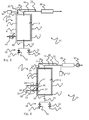
- Fig. 2 shows that the container 1 is connected to a device 14 for functionalizing a plastic container 1.
- the device 14 comprises a first internal space connection unit 15 which is releasably connected to the first internal space connection 10, and a second internal space connection unit 16 which is releasably connected to the second internal space connection 11.
- reactive gas from a reactive gas source 17 is fed into the internal space 3 via the internal space control means 18 for the treatment time 8, and discharged via the second internal space connection 11.
- flushing gas from a flushing gas source 33 is fed into the internal space 3 via the internal space control means 18 and discharged via the second internal space connection 11.
- the second internal space connection unit 16 is part of an internal space gas outlet line 19, through which the exhaust gas is discharged from the internal space 3.
- a fluorine absorber 20 is formed in the internal space gas outlet line 19, in which the fluorine still contained in the exhaust gas is absorbed and therefore removed from the exhaust gas. Release of fluorine to the environment can thus be effectively prevented.
- the internal space control means 18 comprises a first valve 21, by which the supply of reactive gas from the source 17 can be switched on and off, and in particular also regulated or adjusted.
- the internal space control means 18 furthermore comprises a second valve by which flushing gas, preferably nitrogen (N 2 ), from the source 33 can be delivered in a controlled way.
- flushing gas preferably nitrogen (N 2 )
- the reactive gas is delivered in a controlled way via the first valve 21, while nitrogen or an inert gas is delivered in a controlled way via the second valve 22.
- the volumetric composition of the reactive gas can thus be freely regulated. It is, however, preferable to supply an already prepared reactive gas from the source 17 via the first valve 21.
- the measurement sensor 13 and the internal space control means 18 may be connected to a common drive instrument, which triggers shutdown of the reactive gas supply and/or the initiation of a flushing process when a predetermined limit value of the reactive substance concentration in the intermediate space is exceeded, and operates the internal space control means 18 accordingly.
- the internal space connection units 15, 16 and the intermediate space connection unit 23 are formed so that they can be connected simply and reversibly to the container 1 to be functionalized.
- Fig. 3 schematically shows a second exemplary embodiment of the device 14 according to the invention for carrying out the method according to the invention.
- the intermediate space 6 of the container 1 can also be flushed.
- a first intermediate space connection unit 23 via which a flushing gas, for example nitrogen or air, can be introduced into the intermediate space 6 of the container 1, is connected to the first intermediate space connection 12.
- the container 1 furthermore has a second intermediate space connection 24, to which a second intermediate space connection unit 25 is connected.
- the latter is part of an intermediate space gas outlet line 26.
- a measurement sensor 13 for monitoring the concentration of the reactive substance in the intermediate space gas outlet line 26 is connected to the intermediate space gas outlet line 26. If the concentration of reactive substance in the exhaust gas flowing through the intermediate space gas outlet line lies above a predeterminable limit value, the supply of reactive gas is stopped and a process of flushing the internal space 3 of the container 1 is initiated. To this end, the internal space control means 18 are operated accordingly.
- the intermediate space gas outlet line 26 opens into the internal space gas outlet line 19, so that the exhaust gas which is taken from the intermediate space 6 is likewise fed through the absorber 20.
- Fig. 4 shows another exemplary embodiment of the device 14 according to the invention for functionalizing a plastic container 1.
- both the internal space 3 and the intermediate space 6 of the container 1 are flushed with air.
- the container 1 has a third internal space connection 27 to which a third internal space connection unit 28 is connected.
- the third internal space connection unit 28 which has a third valve 29 by which the inlet flow of gas can be opened and closed in a controlled way, flushing air flows into the internal space 3 during the flushing times 7, 9, and is extracted through the absorber 20 via the second internal space connection 11.
- the intermediate space 6 is also flushed in this exemplary embodiment, preferably with air, via the first intermediate space connection 12 and a first intermediate space connection unit 23, which is connected thereto and has a fourth valve 30.
- the fourth valve 30 is part of intermediate space control means 34 for controlling the flow of flushing gas from a source 33 through the first intermediate space connection unit 23.
- the measurement sensor 13 is formed upstream of the absorber 20 but downstream of the opening 31 of the intermediate space gas outlet line 26 into the internal space gas outlet line 19.
- a delivery means 32 which may preferably comprise a pump or a compressor, is furthermore formed. A gas flow can be delivered through the internal space 3 and/or the intermediate space 6 by this delivery means 32.
- the method according to the invention for functionalizing a plastic container 1 even makes it possible to functionalize containers 1 with very large volumes, which otherwise could not be functionalized or could be functionalized only with great difficulty.
- the method according to the invention is suitable for functionalizing containers 1 which have a volume of more than 1 m 3 and up to 60 m 3 or more. These sizes refer to the volume of the internal space 3.
- Such containers 1 are particularly preferably used for holding and storing chemicals, in particular acids or bases.
Landscapes
- Chemical & Material Sciences (AREA)
- General Chemical & Material Sciences (AREA)
- Health & Medical Sciences (AREA)
- Chemical Kinetics & Catalysis (AREA)
- Medicinal Chemistry (AREA)
- Polymers & Plastics (AREA)
- Organic Chemistry (AREA)
- Apparatus For Disinfection Or Sterilisation (AREA)
- Treatments Of Macromolecular Shaped Articles (AREA)
- Details Of Rigid Or Semi-Rigid Containers (AREA)
Abstract
a. fluorine; and
b. chlorine
is fed for at least a predeterminable treatment time (8) into the internal space (3), which is subsequently flushed for at least a predeterminable flushing time (7, 9) with a flushing gas free of reactive substances.
Description
- The present invention relates to a method for functionalizing, in particular fluorinating, a plastic container. The method according to the invention is preferably employed for the fluorination of containers with large volumes, in particular with volumes of 1 m3 (cubic metre) or more up to 60 m3 or more.
- Methods for the fluorination of, in particular, small objects or limited geometries are known for example from
DE-A-10 2007 060 913 orDE-A-10 2008 059 125 . These methods must generally be carried out so that no reactive gas, i.e. in particular no gas containing fluorine or chlorine, can escape into the environment. Besides preventing environmental damage, this also serves to prevent harm to the health of the operating personnel. For this reason, such functionalization methods, for example gas phase fluorination, are always carried out in such a way that the reactive gas is suctioned away and it is possible to prevent individuals from coming in contact with the reactive gas. In particular, these methods are carried out in appropriately equipped rooms, for example clean rooms. - The methods known from the prior art reach their limits in particular when the objects to be fluorinated have large volumes. For large containers, for example storage containers for storing lyes or bases, which may have a volume of up to 60 m3 or more, it has not previously been possible to carry out fluorination.
- The present invention relates to a method, to a corresponding device and to a corresponding container, with which the problems known from the prior art can at least partially be overcome. In particular, it is an object to provide a method for functionalizing a container, with which even containers with large volumes can be functionalized reliably.
- These objects are achieved by the features of the independent claims. The respective dependent claims relate to corresponding refinements.
- The features referred to individually in the patent claims may be combined with one another in any desired technologically feasible way and may be supplemented with explanatory information from the description, in which further alternative embodiments of the invention are presented.
- The present invention relates to a method for functionalizing a plastic container, the container being bounded externally by a double wall which consists of an inner wall forming an internal space of the container and an outer wall surrounding the former, an intermediate space being formed between the inner wall and the outer wall, wherein a reactive gas comprising at least one of the following reactive substances:
- a. fluorine; and
- b. chlorine
- The functionalization of surfaces is intended to mean the at least partial replacement of hydrogen atoms in plastic surfaces by other atoms, for example fluorine or chlorine. The functionalization serves to modify the surface properties of the surface of the plastics. This involves in particular the changing of properties such as for example the static and/or sliding friction, the permeation coefficient, etc.
- The method according to the invention is preferably used for fluorination, in which the reactive substance comprises fluorine. In this case, the reactive gas preferably consists of a mixture of fluorine and an inert gas, for example nitrogen (N2).
- A flushing gas free of reactive substances is intended to mean in particular an inert gas, for example nitrogen or air, in which the concentration of the reactive substances is less than 0.2 vol%, preferably less than 0.01 vol% and particularly preferably 0.001 vol% or less. The term flushing is intended to mean, for example, a continuous flushing process in which the flushing gas flows through the container for the flushing time, or a discontinuous flushing process in which the flushing gas is introduced to the container, left therein for the flushing time and then removed therefrom.
- By the method according to the invention, functionalization of only the inner side of the inner wall of the container takes place. During normal operation, no reactive substance enters the intermediate space between the inner wall and the outer wall. The outer wall is consequently used as an additional safety measure, since, even if the inner wall breaks or has a leak, it prevents the reactive gas or reactive substance from being released into the environment. This protects the operating personnel reliably against any contamination with reactive substance during the functionalization, and prevents the latter from being released into the environment. Thus, even containers with very large volumes, for example with an internal space volume of 1 m3 or more, preferably 5 m3 or more, particularly preferably 10, 20, 30 or 40 m3 or more can be functionalized, and in particular fluorinated. For containers of this order of magnitude, functionalization by the method known from the prior art is virtually impossible without tolerating a possible hazard for the environment and the operating personnel in the event of a leak.
- According to an advantageous configuration of the method according to the invention, the concentration of the at least one reactive substance in the intermediate space is monitored at least during the at least one treatment time.
- To this end, a corresponding measurement sensor is formed in the intermediate space or this intermediate space is connected or connectable to a corresponding measurement sensor, so that the gas contained in the intermediate space also comes in contact with the measurement sensor. Thus, even if a breach of the inner wall occurs, an alarm is triggered and optionally the functionalization is stopped and a flushing phase is entered.
- Monitoring the concentration of the at least one reactive substance in the intermediate space is a further safety measure which increases the safety of the environment and the operating personnel. Thus, functionalizations can be carried out safely even for large containers. With these functionalized containers, it is not necessary to use high-grade plastics, for example for storing bases or acids. Overall, these containers can therefore be produced more economically.
- According to another advantageous configuration of the method according to the invention, the concentration of the at least one reactive substance in the intermediate space is monitored by at least one of the following measures:
- a. connecting the intermediate space to a measurement sensor for monitoring the concentration of the at least one reactive substance; and
- b. flushing the intermediate space with flushing gas, the concentration of the at least one reactive substance in the flushing gas being monitored downstream of the intermediate space.
- This allows on the one hand direct introduction of the measurement sensor into the intermediate space or into connection with the intermediate space, and on the other hand monitoring of the exhaust gas in a process of flushing the intermediate space, respectively for the concentration of the reactive substance.
- According to another advantageous configuration of the method according to the invention, the feeding of the reactive gas into the internal space is interrupted when the concentration of the at least one reactive substance in the intermediate space exceeds a predeterminable limit value.
- If the predeterminable limit value for the concentration of the reactive substance in the intermediate space is exceeded, this is interpreted as an indication that there is a breach of the inner wall and reactive gas comprising reactive substance has thus entered the intermediate space from the internal space. In this case - if a treatment time is currently in progress - the treatment is stopped and the supply of the reactive gas into the internal space is interrupted. The limit value is preferably established so that its being exceeded can reliably be attributed to a leak of the inner wall.
- According to another advantageous configuration of the method according to the invention, flushing of the intermediate space with flushing gas is initiated when the concentration of the at least one reactive substance in the intermediate space exceeds a predeterminable limit value.
- If there is a breach of the inner wall and the concentration of the reactive substance in the intermediate space exceeds a predeterminable limit value, a flushing process is immediately initiated in order to flush reactive substance still contained in the internal space and now also present in the intermediate space out of the container. At the same time, it is possible to store or use these data so as to directly signal a product defect, since a leak of the inner wall is not tolerable specifically when the container is intended to use as a holding container for acids or bases.
- Another aspect of the present invention provides a device for carrying out the method according to the invention, comprising at least one internal space connection unit for connecting to an internal space connection of the container in order to supply and/or discharge at least one of the following gases
- a. the reactive gas; and
- b. a flushing gas for flushing the internal space, to/from the internal space of the container,
and at least one intermediate space connection unit for connecting to an intermediate space connection of the container in order to connect the intermediate space of the container to a measurement sensor for monitoring the concentration of the at least one reactive substance in the intermediate space. - The at least one intermediate space connection unit and the at least one internal space connection unit are in particular configured so that they can be reversibly connected to the corresponding internal space connections and intermediate space connections. The device according to the invention preferably has drive means, which reads the data from the measurement sensor and controls and regulates the supply of reactive gas and/or flushing gas to the internal space and/or to the intermediate space with the aid of them, for example by driving valves accordingly.
- According to an advantageous refinement of the device according to the invention, internal space control means are formed, by which the at least one internal space connection unit can be connected to a source of reactive gas or to a source of flushing gas.
- The internal space control means preferably comprise one or more valves, with which the supply of reactive gas and/or flushing gas can be adjusted and preferably also regulated.
- According to another advantageous configuration of the device according to the invention, an internal space gas outlet line having an absorber for the at least one reactive substance is formed, to which the at least one internal space connection unit can be connected.
- Thus, the gas which is contained in the internal space of the container can be extracted via the internal space gas outlet line, preferably by a delivery means such as a pump, while flowing through the absorber for the at least one reactive substance. This prevents the reactive substance from being released to the environment. The absorber is preferably monitored in respect of its absorptivities for the reactive substance, in order to allow prompt changing of the absorber. In particular, it has colour coding which indicates when a certain reactive substance concentration has been reached in a rear part, for example in the last third of the absorber, so as to allow prompt changing of the absorber.
- According to another advantageous configuration of the device according to the invention, intermediate space control means are formed, by which the at least one intermediate space connection unit can be connected to a source of flushing gas.
- A flushing gas supply to the intermediate space can thus be regulated. The intermediate space control means preferably comprise at least one valve, preferably a controllable valve.
- According to another advantageous configuration of the device according to the invention, an intermediate space gas outlet line is formed, which can be connected to the at least one intermediate space connection unit in which a measurement sensor for the at least one reactive substance is formed.
- Monitoring of the intermediate space can thus be carried out by monitoring the concentration of the reactive substance in the intermediate space gas outlet line.
- Another aspect of the present invention provides a plastic container for functionalization by the method according to the invention and/or for functionalization in a device according to the invention, the container being bounded externally by a double wall which consists of an inner wall forming an internal space of the container and an outer wall surrounding the former, an intermediate space being formed between the inner wall and the outer wall, comprising at least one internal space connection through which at least one gas can be fed into the internal space of the container and/or discharged therefrom, and at least one intermediate space connection through which the intermediate space can be connected to a measurement sensor for the at least one reactive substance.
- The internal space connections and the intermediate space connections are preferably configured so that they can be connected to a corresponding device.
- The details and advantages disclosed for the method according to the invention can also be adapted and applied to the device according to the invention, and vice versa.
- The invention will be explained by way of example below with the aid of the appended figures, without being restricted to the exemplary embodiments shown therein. Schematically:
- Fig. 1:
- shows an explanation of the procedure of the method according to the invention;
- Fig. 2:
- shows a first exemplary embodiment of a device according to the invention;
- Fig. 3:
- shows a second exemplary embodiment of a device according to the invention;
- Fig. 4:
- shows a third exemplary embodiment of a device according to the invention.
- In the method according to the invention for functionalizing a
plastic container 1, as shown for example inFig. 2 , thiscontainer 1 has a double wall 2 which bounds thecontainer 1 externally. The double wall 2 comprises aninner wall 4 forming aninternal space 3 of the container, and an outer wall 5 surrounding the former. Anintermediate space 6 is formed between theinner wall 4 and the outer wall 5. In the method according to the invention, a reactive gas comprising fluorine and/or chlorine, preferably fluorine, preferably a mixture of nitrogen and fluorine with fluorine as the reactive substance, is fed into theinternal space 3. According toFig. 1 , theinternal space 3 is initially flushed for afirst flushing time 7 with a flushing gas, which is essentially free of the reactive substances used. To this end, the flushing gas is introduced one or more times into theintermediate space 3 and then removed therefrom. Subsequently, the reactive gas is introduced into the intermediate space for atreatment time 8. This is followed by flushing theintermediate space 3 again for asecond flushing time 9. - The reactive gas preferably comprises a mixture of fluorine and nitrogen, in particular 10 vol% fluorine in 90 vol% nitrogen or 5 vol% fluorine in 95 vol% nitrogen. The length of the
treatment times 8 and theflushing times - According to the invention, the double wall 2 of the
container 1 is used as a safety measure. Functionalization is carried out, in particular fluorination, in particular of the inner side of theinner wall 4 of thecontainer 1. The double wall 2 and theintermediate space 6, between theinner wall 4 and the outer wall 5, preferably serve as a safety measure by which no reactive gas can emerge through the outer wall 5 even if theinner wall 4 has a leak. - In the first exemplary embodiment according to
Fig. 2 , thecontainer 1 has a firstinternal space connection 10 and a secondinternal space connection 11. Via the twointernal space connections internal space 3 of thecontainer 1 and discharge them therefrom. Thecontainer 1 furthermore has a firstintermediate space connection 12. Connected gas-tightly thereto via an intermediatespace connection unit 23, there is ameasurement sensor 13 by which the fluorine content of the gas in theintermediate space 6 is monitored. If themeasurement sensor 13 indicates a fluorine concentration which lies above a predeterminable limit value, a leak in theinner wall 4 of thecontainer 1 is inferred. Appropriate measures are then initiated, and in particular the supply of reaction gas to theinternal space 3 is interrupted, if there still is one. As an alternative or in addition, a process of flushing theinternal space 3 and theintermediate space 6 is initiated. In this way, the fluorine which is used as the reactive gas in this exemplary embodiment is removed from theinternal space 3 and optionally also from theintermediate space 6, so as to prevent release to the environment and possible users being placed at risk. -
Fig. 2 shows that thecontainer 1 is connected to adevice 14 for functionalizing aplastic container 1. Thedevice 14 comprises a first internalspace connection unit 15 which is releasably connected to the firstinternal space connection 10, and a second internalspace connection unit 16 which is releasably connected to the secondinternal space connection 11. - During operation, reactive gas from a
reactive gas source 17 is fed into theinternal space 3 via the internal space control means 18 for thetreatment time 8, and discharged via the secondinternal space connection 11. During theflushing times gas source 33 is fed into theinternal space 3 via the internal space control means 18 and discharged via the secondinternal space connection 11. The second internalspace connection unit 16 is part of an internal spacegas outlet line 19, through which the exhaust gas is discharged from theinternal space 3. Afluorine absorber 20 is formed in the internal spacegas outlet line 19, in which the fluorine still contained in the exhaust gas is absorbed and therefore removed from the exhaust gas. Release of fluorine to the environment can thus be effectively prevented. - The internal space control means 18 comprises a
first valve 21, by which the supply of reactive gas from thesource 17 can be switched on and off, and in particular also regulated or adjusted. The internal space control means 18 furthermore comprises a second valve by which flushing gas, preferably nitrogen (N2), from thesource 33 can be delivered in a controlled way. In an alternative configuration, the reactive gas is delivered in a controlled way via thefirst valve 21, while nitrogen or an inert gas is delivered in a controlled way via thesecond valve 22. The volumetric composition of the reactive gas can thus be freely regulated. It is, however, preferable to supply an already prepared reactive gas from thesource 17 via thefirst valve 21. - The
measurement sensor 13 and the internal space control means 18 may be connected to a common drive instrument, which triggers shutdown of the reactive gas supply and/or the initiation of a flushing process when a predetermined limit value of the reactive substance concentration in the intermediate space is exceeded, and operates the internal space control means 18 accordingly. Preferably, the internalspace connection units space connection unit 23 are formed so that they can be connected simply and reversibly to thecontainer 1 to be functionalized. -
Fig. 3 schematically shows a second exemplary embodiment of thedevice 14 according to the invention for carrying out the method according to the invention. Here - as well as in the description of the exemplary embodiment according toFig. 4 - only the differences from the first exemplary embodiment will be explained below, and to this extent reference is made to the comments regarding the first exemplary embodiment. In contrast to the first exemplary embodiment according toFig. 2 , in this case theintermediate space 6 of thecontainer 1 can also be flushed. To this end a first intermediatespace connection unit 23 via which a flushing gas, for example nitrogen or air, can be introduced into theintermediate space 6 of thecontainer 1, is connected to the firstintermediate space connection 12. Thecontainer 1 furthermore has a secondintermediate space connection 24, to which a second intermediatespace connection unit 25 is connected. The latter is part of an intermediate spacegas outlet line 26. Ameasurement sensor 13 for monitoring the concentration of the reactive substance in the intermediate spacegas outlet line 26 is connected to the intermediate spacegas outlet line 26. If the concentration of reactive substance in the exhaust gas flowing through the intermediate space gas outlet line lies above a predeterminable limit value, the supply of reactive gas is stopped and a process of flushing theinternal space 3 of thecontainer 1 is initiated. To this end, the internal space control means 18 are operated accordingly. - The intermediate space
gas outlet line 26 opens into the internal spacegas outlet line 19, so that the exhaust gas which is taken from theintermediate space 6 is likewise fed through theabsorber 20. -
Fig. 4 shows another exemplary embodiment of thedevice 14 according to the invention for functionalizing aplastic container 1. In this exemplary embodiment, both theinternal space 3 and theintermediate space 6 of thecontainer 1 are flushed with air. Correspondingly, thecontainer 1 has a thirdinternal space connection 27 to which a third internalspace connection unit 28 is connected. Via the third internalspace connection unit 28, which has athird valve 29 by which the inlet flow of gas can be opened and closed in a controlled way, flushing air flows into theinternal space 3 during theflushing times absorber 20 via the secondinternal space connection 11. Theintermediate space 6 is also flushed in this exemplary embodiment, preferably with air, via the firstintermediate space connection 12 and a first intermediatespace connection unit 23, which is connected thereto and has afourth valve 30. Thefourth valve 30 is part of intermediate space control means 34 for controlling the flow of flushing gas from asource 33 through the first intermediatespace connection unit 23. In this exemplary embodiment, themeasurement sensor 13 is formed upstream of theabsorber 20 but downstream of theopening 31 of the intermediate spacegas outlet line 26 into the internal spacegas outlet line 19. A delivery means 32, which may preferably comprise a pump or a compressor, is furthermore formed. A gas flow can be delivered through theinternal space 3 and/or theintermediate space 6 by this delivery means 32. - The method according to the invention for functionalizing a
plastic container 1 even makes it possible to functionalizecontainers 1 with very large volumes, which otherwise could not be functionalized or could be functionalized only with great difficulty. In particular, the method according to the invention is suitable for functionalizingcontainers 1 which have a volume of more than 1 m3 and up to 60 m3 or more. These sizes refer to the volume of theinternal space 3.Such containers 1 are particularly preferably used for holding and storing chemicals, in particular acids or bases. -
- 1
- container
- 2
- double wall
- 3
- internal space
- 4
- inner wall
- 5
- outer wall
- 6
- intermediate space
- 7
- first flushing time
- 8
- treatment time
- 9
- second flushing time
- 10
- first internal space connection
- 11
- second internal space connection
- 12
- first intermediate space connection
- 13
- measurement sensor
- 14
- device for functionalizing a container
- 15
- first internal space connection unit
- 16
- second internal space connection unit
- 17
- reactive gas source
- 18
- internal space control means
- 19
- internal space gas outlet line
- 20
- absorber
- 21
- first valve
- 22
- second valve
- 23
- first intermediate space connection unit
- 24
- second intermediate space connection
- 25
- second intermediate space connection unit
- 26
- intermediate space gas outlet line
- 27
- third internal space connection
- 28
- third internal space connection unit
- 29
- third valve
- 30
- fourth valve
- 31
- opening
- 32
- delivery means
- 33
- flushing gas source
- 34
- intermediate space control means
Claims (11)
- Method for functionalizing a plastic container (1), the container (1) being bounded externally by a double wall (2) which consists of an inner wall (4) forming an internal space (3) of the container (1) and an outer wall (5) surrounding the former, an intermediate space (6) being formed between the inner wall (4) and the outer wall (5), wherein a reactive gas comprising at least one of the following reactive substances:a. fluorine; andb. chlorine
is fed for at least a predeterminable treatment time (8) into the internal space (3), which is subsequently flushed for at least a predeterminable flushing time (7, 9) with a flushing gas free of reactive substances. - Method according to Claim 1, wherein the concentration of the at least one reactive substance in the intermediate space (6) is monitored at least during the at least one treatment time (8).
- Method according to Claim 2, wherein the concentration of the at least one reactive substance in the intermediate space (6) is monitored by at least one of the following measures:a. connecting the intermediate space (6) to a measurement sensor (13) for monitoring the concentration of the at least one reactive substance; andb. flushing the intermediate space (6) with flushing gas, the concentration of the at least one reactive substance in the flushing gas being monitored downstream of the intermediate space (6).
- Method according to one of Claims 2 and 3, wherein the feeding of the reactive gas into the internal space (3) is interrupted when the concentration of the at least one reactive substance in the intermediate space (6) exceeds a predeterminable limit value.
- Method according to one of Claims 2 to 4, wherein flushing of the intermediate space (3) with flushing gas is initiated when the concentration of the at least one reactive substance in the intermediate space (6) exceeds a predeterminable limit value.
- Device (14) for carrying out the method according to one of the preceding claims, comprising at least one internal space connection unit (15, 16, 28) for connecting to an internal space connection (10, 11, 27) of the container (1) in order to supply and/or discharge at least one of the following gasesa. the reactive gas; andb. a flushing gas for flushing the internal space, to/from the internal space (3) of the container (1), and at least one intermediate space connection unit (23, 25) for connecting to an intermediate space connection (12, 24) of the container (1) in order to connect the intermediate space (3) of the container (1) to a measurement sensor (13) for monitoring the concentration of the at least one reactive substance in the intermediate space (6).
- Device (14) according to Claim 6, wherein internal space control means (18) are formed, by which the at least one internal space connection unit (15, 16, 28) can be connected to a source (16) of reactive gas or to a source (33) of flushing gas.
- Device (14) according to Claim 6 or 7, wherein an internal space gas outlet line (19) having an absorber (20) for the at least one reactive substance is formed, to which the at least one internal space connection unit (15, 16, 28) can be connected.
- Device (14) according to one of Claims 6 to 8, wherein intermediate space control means (34) are formed, by which the at least one intermediate space connection unit (23, 25) can be connected to a source (33) of flushing gas.
- Device (14) according to one of Claims 6 to 9, wherein an intermediate space gas outlet line (26) is formed, which can be connected to the at least one intermediate space connection unit (23, 25) in which a measurement sensor (13) for the at least one reactive substance is formed.
- Plastic container (1) for functionalization by the method according to one of Claims 1 to 5 and/or for functionalization in a device (14) according to one of Claims 6 to 10, the container (1) being bounded externally by a double wall (2) which consists of an inner wall (4) forming an internal space (3) of the container (1) and an outer wall (5) surrounding the former, an intermediate space (6) being formed between the inner wall (4) and the outer wall (5), comprising at least one internal space connection (10, 11, 27) through which at least one gas can be fed into the internal space (3) of the container (1) and/or discharged therefrom, and at least one intermediate space connection (23, 25) through which the intermediate space (6) can be connected to a measurement sensor (13) for the at least one reactive substance.
Applications Claiming Priority (1)
| Application Number | Priority Date | Filing Date | Title |
|---|---|---|---|
| DE102010055301A DE102010055301A1 (en) | 2010-12-21 | 2010-12-21 | Method for functionalizing a container and device for carrying out this method and corresponding container |
Publications (2)
| Publication Number | Publication Date |
|---|---|
| EP2468806A1 true EP2468806A1 (en) | 2012-06-27 |
| EP2468806B1 EP2468806B1 (en) | 2017-09-13 |
Family
ID=45065728
Family Applications (1)
| Application Number | Title | Priority Date | Filing Date |
|---|---|---|---|
| EP11189761.7A Not-in-force EP2468806B1 (en) | 2010-12-21 | 2011-11-18 | Method for functionalizing a container and device for carrying out this method and corresponding container |
Country Status (2)
| Country | Link |
|---|---|
| EP (1) | EP2468806B1 (en) |
| DE (1) | DE102010055301A1 (en) |
Cited By (1)
| Publication number | Priority date | Publication date | Assignee | Title |
|---|---|---|---|---|
| CN103630676A (en) * | 2013-11-29 | 2014-03-12 | 沈阳理工大学 | A rubber surface fluorination modification test device |
Citations (4)
| Publication number | Priority date | Publication date | Assignee | Title |
|---|---|---|---|---|
| GB2089950A (en) * | 1980-12-22 | 1982-06-30 | Duncan Ronald Frederick Henry | Thermally insulated containers |
| US20080026143A1 (en) * | 2006-07-25 | 2008-01-31 | Michael Clark Webb | Process for flourinating piping |
| DE102007060913A1 (en) | 2007-12-14 | 2009-06-18 | Air Liquide Deutschland Gmbh | Device for treating molded plastic parts with treatment gas e.g. fluorine or chlorine, comprises treatment unit comprising treatment chamber filled with the treatment gas, and conveyor for moving the molded parts to the treatment unit |
| DE102008059125A1 (en) | 2008-11-26 | 2010-05-27 | Air Liquide Deutschland Gmbh | Method and device for functionalizing a target area of a surface |
Family Cites Families (3)
| Publication number | Priority date | Publication date | Assignee | Title |
|---|---|---|---|---|
| DE102006012366A1 (en) * | 2006-03-17 | 2007-09-20 | Air Liquide Deutschland Gmbh | Process for modifying the surface of plastic moldings by fluorine-initiated oxidation |
| DE102006013681A1 (en) * | 2006-03-24 | 2007-09-27 | Air Liquide Deutschland Gmbh | Fluorination of plastics involves subjecting plastic articles to gas-phase fluorination at atmospheric pressure in reaction chamber |
| WO2010077862A2 (en) * | 2008-12-15 | 2010-07-08 | Tbs Technologies, Llc | Apparatus and methods for controlling chlorine dioxide concentration |
-
2010
- 2010-12-21 DE DE102010055301A patent/DE102010055301A1/en not_active Withdrawn
-
2011
- 2011-11-18 EP EP11189761.7A patent/EP2468806B1/en not_active Not-in-force
Patent Citations (4)
| Publication number | Priority date | Publication date | Assignee | Title |
|---|---|---|---|---|
| GB2089950A (en) * | 1980-12-22 | 1982-06-30 | Duncan Ronald Frederick Henry | Thermally insulated containers |
| US20080026143A1 (en) * | 2006-07-25 | 2008-01-31 | Michael Clark Webb | Process for flourinating piping |
| DE102007060913A1 (en) | 2007-12-14 | 2009-06-18 | Air Liquide Deutschland Gmbh | Device for treating molded plastic parts with treatment gas e.g. fluorine or chlorine, comprises treatment unit comprising treatment chamber filled with the treatment gas, and conveyor for moving the molded parts to the treatment unit |
| DE102008059125A1 (en) | 2008-11-26 | 2010-05-27 | Air Liquide Deutschland Gmbh | Method and device for functionalizing a target area of a surface |
Cited By (1)
| Publication number | Priority date | Publication date | Assignee | Title |
|---|---|---|---|---|
| CN103630676A (en) * | 2013-11-29 | 2014-03-12 | 沈阳理工大学 | A rubber surface fluorination modification test device |
Also Published As
| Publication number | Publication date |
|---|---|
| DE102010055301A1 (en) | 2012-06-21 |
| EP2468806B1 (en) | 2017-09-13 |
Similar Documents
| Publication | Publication Date | Title |
|---|---|---|
| CA2999424C (en) | Loading system and method of use thereof | |
| JP5891177B2 (en) | Liquid dispensing system with gas removal and detection capability | |
| JP5186583B2 (en) | Method and system for liquid dispensing with headspace degassing | |
| JP5455654B2 (en) | How to remove the contents in a pipe with an air system | |
| US10569265B2 (en) | Efficient in-situ catalyst sulfiding methods and systems | |
| JP2007524793A (en) | Automatic switching system for switching gas storage and distribution containers in multiple container arrays. | |
| JP2011513045A (en) | Disinfectant container, disinfectant manufacturing apparatus and manufacturing method | |
| EP2337985B1 (en) | Bundle trailer for gas delivery | |
| CN106488882A (en) | method used to fill the container | |
| FR2957806A1 (en) | MEDICAL GAS DISTRIBUTION SYSTEM WITH AUTOMATIC DETECTION AND DRIVING IN CASE OF PRESSURE DROP | |
| EP2468806B1 (en) | Method for functionalizing a container and device for carrying out this method and corresponding container | |
| US9353585B2 (en) | On-the-fly acid blender with sampling equipment | |
| CN104183520B (en) | Material supply device | |
| CN101539070B (en) | Propellant blowing device in engine pipelines | |
| EP1557245A1 (en) | Isolator system with a robot in a sterile work chamber | |
| JP6653276B2 (en) | Process fluid sampling system | |
| AU2009220989B2 (en) | On-the-fly acid blender with sampling equipment | |
| JP5002437B2 (en) | Treatment filtration device and metal ion monitor using the same | |
| FR2834083A1 (en) | Injecting carbon dioxide into a liquid to be treated, controlled by the measurement of a characteristic of the liquid to be treated | |
| EP3519304B1 (en) | A propellant filling apparatus | |
| JP2005024068A (en) | Halogen gas or halogen-containing gas supply device | |
| US20250314408A1 (en) | Kit, system, and associated method for filling sealed direct inject delivery cartridges with refrigerant gas additives | |
| KR200388468Y1 (en) | Apparatus for charging liquid of bubble vessel | |
| EP1679467A1 (en) | System for supplying halogen gas or halogen containing gas and method thereof |
Legal Events
| Date | Code | Title | Description |
|---|---|---|---|
| AK | Designated contracting states |
Kind code of ref document: A1 Designated state(s): AL AT BE BG CH CY CZ DE DK EE ES FI FR GB GR HR HU IE IS IT LI LT LU LV MC MK MT NL NO PL PT RO RS SE SI SK SM TR |
|
| AX | Request for extension of the european patent |
Extension state: BA ME |
|
| PUAI | Public reference made under article 153(3) epc to a published international application that has entered the european phase |
Free format text: ORIGINAL CODE: 0009012 |
|
| 17P | Request for examination filed |
Effective date: 20121129 |
|
| 17Q | First examination report despatched |
Effective date: 20130610 |
|
| STAA | Information on the status of an ep patent application or granted ep patent |
Free format text: STATUS: EXAMINATION IS IN PROGRESS |
|
| GRAP | Despatch of communication of intention to grant a patent |
Free format text: ORIGINAL CODE: EPIDOSNIGR1 |
|
| STAA | Information on the status of an ep patent application or granted ep patent |
Free format text: STATUS: GRANT OF PATENT IS INTENDED |
|
| INTG | Intention to grant announced |
Effective date: 20170412 |
|
| GRAS | Grant fee paid |
Free format text: ORIGINAL CODE: EPIDOSNIGR3 |
|
| GRAA | (expected) grant |
Free format text: ORIGINAL CODE: 0009210 |
|
| STAA | Information on the status of an ep patent application or granted ep patent |
Free format text: STATUS: THE PATENT HAS BEEN GRANTED |
|
| AK | Designated contracting states |
Kind code of ref document: B1 Designated state(s): AL AT BE BG CH CY CZ DE DK EE ES FI FR GB GR HR HU IE IS IT LI LT LU LV MC MK MT NL NO PL PT RO RS SE SI SK SM TR |
|
| REG | Reference to a national code |
Ref country code: GB Ref legal event code: FG4D |
|
| REG | Reference to a national code |
Ref country code: CH Ref legal event code: EP |
|
| REG | Reference to a national code |
Ref country code: IE Ref legal event code: FG4D |
|
| REG | Reference to a national code |
Ref country code: AT Ref legal event code: REF Ref document number: 928078 Country of ref document: AT Kind code of ref document: T Effective date: 20171015 |
|
| REG | Reference to a national code |
Ref country code: DE Ref legal event code: R096 Ref document number: 602011041516 Country of ref document: DE |
|
| REG | Reference to a national code |
Ref country code: NL Ref legal event code: MP Effective date: 20170913 |
|
| REG | Reference to a national code |
Ref country code: LT Ref legal event code: MG4D |
|
| PG25 | Lapsed in a contracting state [announced via postgrant information from national office to epo] |
Ref country code: FI Free format text: LAPSE BECAUSE OF FAILURE TO SUBMIT A TRANSLATION OF THE DESCRIPTION OR TO PAY THE FEE WITHIN THE PRESCRIBED TIME-LIMIT Effective date: 20170913 Ref country code: HR Free format text: LAPSE BECAUSE OF FAILURE TO SUBMIT A TRANSLATION OF THE DESCRIPTION OR TO PAY THE FEE WITHIN THE PRESCRIBED TIME-LIMIT Effective date: 20170913 Ref country code: LT Free format text: LAPSE BECAUSE OF FAILURE TO SUBMIT A TRANSLATION OF THE DESCRIPTION OR TO PAY THE FEE WITHIN THE PRESCRIBED TIME-LIMIT Effective date: 20170913 Ref country code: SE Free format text: LAPSE BECAUSE OF FAILURE TO SUBMIT A TRANSLATION OF THE DESCRIPTION OR TO PAY THE FEE WITHIN THE PRESCRIBED TIME-LIMIT Effective date: 20170913 Ref country code: NO Free format text: LAPSE BECAUSE OF FAILURE TO SUBMIT A TRANSLATION OF THE DESCRIPTION OR TO PAY THE FEE WITHIN THE PRESCRIBED TIME-LIMIT Effective date: 20171213 |
|
| REG | Reference to a national code |
Ref country code: AT Ref legal event code: MK05 Ref document number: 928078 Country of ref document: AT Kind code of ref document: T Effective date: 20170913 |
|
| PG25 | Lapsed in a contracting state [announced via postgrant information from national office to epo] |
Ref country code: ES Free format text: LAPSE BECAUSE OF FAILURE TO SUBMIT A TRANSLATION OF THE DESCRIPTION OR TO PAY THE FEE WITHIN THE PRESCRIBED TIME-LIMIT Effective date: 20170913 Ref country code: GR Free format text: LAPSE BECAUSE OF FAILURE TO SUBMIT A TRANSLATION OF THE DESCRIPTION OR TO PAY THE FEE WITHIN THE PRESCRIBED TIME-LIMIT Effective date: 20171214 Ref country code: RS Free format text: LAPSE BECAUSE OF FAILURE TO SUBMIT A TRANSLATION OF THE DESCRIPTION OR TO PAY THE FEE WITHIN THE PRESCRIBED TIME-LIMIT Effective date: 20170913 Ref country code: BG Free format text: LAPSE BECAUSE OF FAILURE TO SUBMIT A TRANSLATION OF THE DESCRIPTION OR TO PAY THE FEE WITHIN THE PRESCRIBED TIME-LIMIT Effective date: 20171213 Ref country code: LV Free format text: LAPSE BECAUSE OF FAILURE TO SUBMIT A TRANSLATION OF THE DESCRIPTION OR TO PAY THE FEE WITHIN THE PRESCRIBED TIME-LIMIT Effective date: 20170913 |
|
| PG25 | Lapsed in a contracting state [announced via postgrant information from national office to epo] |
Ref country code: NL Free format text: LAPSE BECAUSE OF FAILURE TO SUBMIT A TRANSLATION OF THE DESCRIPTION OR TO PAY THE FEE WITHIN THE PRESCRIBED TIME-LIMIT Effective date: 20170913 |
|
| PG25 | Lapsed in a contracting state [announced via postgrant information from national office to epo] |
Ref country code: CZ Free format text: LAPSE BECAUSE OF FAILURE TO SUBMIT A TRANSLATION OF THE DESCRIPTION OR TO PAY THE FEE WITHIN THE PRESCRIBED TIME-LIMIT Effective date: 20170913 Ref country code: RO Free format text: LAPSE BECAUSE OF FAILURE TO SUBMIT A TRANSLATION OF THE DESCRIPTION OR TO PAY THE FEE WITHIN THE PRESCRIBED TIME-LIMIT Effective date: 20170913 Ref country code: PL Free format text: LAPSE BECAUSE OF FAILURE TO SUBMIT A TRANSLATION OF THE DESCRIPTION OR TO PAY THE FEE WITHIN THE PRESCRIBED TIME-LIMIT Effective date: 20170913 |
|
| PG25 | Lapsed in a contracting state [announced via postgrant information from national office to epo] |
Ref country code: SK Free format text: LAPSE BECAUSE OF FAILURE TO SUBMIT A TRANSLATION OF THE DESCRIPTION OR TO PAY THE FEE WITHIN THE PRESCRIBED TIME-LIMIT Effective date: 20170913 Ref country code: EE Free format text: LAPSE BECAUSE OF FAILURE TO SUBMIT A TRANSLATION OF THE DESCRIPTION OR TO PAY THE FEE WITHIN THE PRESCRIBED TIME-LIMIT Effective date: 20170913 Ref country code: AT Free format text: LAPSE BECAUSE OF FAILURE TO SUBMIT A TRANSLATION OF THE DESCRIPTION OR TO PAY THE FEE WITHIN THE PRESCRIBED TIME-LIMIT Effective date: 20170913 Ref country code: SM Free format text: LAPSE BECAUSE OF FAILURE TO SUBMIT A TRANSLATION OF THE DESCRIPTION OR TO PAY THE FEE WITHIN THE PRESCRIBED TIME-LIMIT Effective date: 20170913 Ref country code: IS Free format text: LAPSE BECAUSE OF FAILURE TO SUBMIT A TRANSLATION OF THE DESCRIPTION OR TO PAY THE FEE WITHIN THE PRESCRIBED TIME-LIMIT Effective date: 20180113 Ref country code: IT Free format text: LAPSE BECAUSE OF FAILURE TO SUBMIT A TRANSLATION OF THE DESCRIPTION OR TO PAY THE FEE WITHIN THE PRESCRIBED TIME-LIMIT Effective date: 20170913 |
|
| REG | Reference to a national code |
Ref country code: DE Ref legal event code: R119 Ref document number: 602011041516 Country of ref document: DE |
|
| PG25 | Lapsed in a contracting state [announced via postgrant information from national office to epo] |
Ref country code: MC Free format text: LAPSE BECAUSE OF FAILURE TO SUBMIT A TRANSLATION OF THE DESCRIPTION OR TO PAY THE FEE WITHIN THE PRESCRIBED TIME-LIMIT Effective date: 20170913 |
|
| PLBE | No opposition filed within time limit |
Free format text: ORIGINAL CODE: 0009261 |
|
| STAA | Information on the status of an ep patent application or granted ep patent |
Free format text: STATUS: NO OPPOSITION FILED WITHIN TIME LIMIT |
|
| PG25 | Lapsed in a contracting state [announced via postgrant information from national office to epo] |
Ref country code: LI Free format text: LAPSE BECAUSE OF NON-PAYMENT OF DUE FEES Effective date: 20171130 Ref country code: CH Free format text: LAPSE BECAUSE OF NON-PAYMENT OF DUE FEES Effective date: 20171130 Ref country code: DK Free format text: LAPSE BECAUSE OF FAILURE TO SUBMIT A TRANSLATION OF THE DESCRIPTION OR TO PAY THE FEE WITHIN THE PRESCRIBED TIME-LIMIT Effective date: 20170913 |
|
| 26N | No opposition filed |
Effective date: 20180614 |
|
| GBPC | Gb: european patent ceased through non-payment of renewal fee |
Effective date: 20171213 |
|
| PG25 | Lapsed in a contracting state [announced via postgrant information from national office to epo] |
Ref country code: LU Free format text: LAPSE BECAUSE OF NON-PAYMENT OF DUE FEES Effective date: 20171118 |
|
| REG | Reference to a national code |
Ref country code: FR Ref legal event code: ST Effective date: 20180731 Ref country code: BE Ref legal event code: MM Effective date: 20171130 |
|
| REG | Reference to a national code |
Ref country code: IE Ref legal event code: MM4A |
|
| PG25 | Lapsed in a contracting state [announced via postgrant information from national office to epo] |
Ref country code: MT Free format text: LAPSE BECAUSE OF NON-PAYMENT OF DUE FEES Effective date: 20171118 |
|
| PG25 | Lapsed in a contracting state [announced via postgrant information from national office to epo] |
Ref country code: IE Free format text: LAPSE BECAUSE OF NON-PAYMENT OF DUE FEES Effective date: 20171118 Ref country code: FR Free format text: LAPSE BECAUSE OF NON-PAYMENT OF DUE FEES Effective date: 20171130 Ref country code: DE Free format text: LAPSE BECAUSE OF NON-PAYMENT OF DUE FEES Effective date: 20180602 |
|
| PG25 | Lapsed in a contracting state [announced via postgrant information from national office to epo] |
Ref country code: GB Free format text: LAPSE BECAUSE OF NON-PAYMENT OF DUE FEES Effective date: 20171213 Ref country code: BE Free format text: LAPSE BECAUSE OF NON-PAYMENT OF DUE FEES Effective date: 20171130 Ref country code: SI Free format text: LAPSE BECAUSE OF FAILURE TO SUBMIT A TRANSLATION OF THE DESCRIPTION OR TO PAY THE FEE WITHIN THE PRESCRIBED TIME-LIMIT Effective date: 20170913 |
|
| PG25 | Lapsed in a contracting state [announced via postgrant information from national office to epo] |
Ref country code: HU Free format text: LAPSE BECAUSE OF FAILURE TO SUBMIT A TRANSLATION OF THE DESCRIPTION OR TO PAY THE FEE WITHIN THE PRESCRIBED TIME-LIMIT; INVALID AB INITIO Effective date: 20111118 |
|
| PG25 | Lapsed in a contracting state [announced via postgrant information from national office to epo] |
Ref country code: CY Free format text: LAPSE BECAUSE OF NON-PAYMENT OF DUE FEES Effective date: 20170913 |
|
| PG25 | Lapsed in a contracting state [announced via postgrant information from national office to epo] |
Ref country code: MK Free format text: LAPSE BECAUSE OF FAILURE TO SUBMIT A TRANSLATION OF THE DESCRIPTION OR TO PAY THE FEE WITHIN THE PRESCRIBED TIME-LIMIT Effective date: 20170913 |
|
| PG25 | Lapsed in a contracting state [announced via postgrant information from national office to epo] |
Ref country code: TR Free format text: LAPSE BECAUSE OF FAILURE TO SUBMIT A TRANSLATION OF THE DESCRIPTION OR TO PAY THE FEE WITHIN THE PRESCRIBED TIME-LIMIT Effective date: 20170913 |
|
| PG25 | Lapsed in a contracting state [announced via postgrant information from national office to epo] |
Ref country code: PT Free format text: LAPSE BECAUSE OF FAILURE TO SUBMIT A TRANSLATION OF THE DESCRIPTION OR TO PAY THE FEE WITHIN THE PRESCRIBED TIME-LIMIT Effective date: 20170913 |
|
| PG25 | Lapsed in a contracting state [announced via postgrant information from national office to epo] |
Ref country code: AL Free format text: LAPSE BECAUSE OF FAILURE TO SUBMIT A TRANSLATION OF THE DESCRIPTION OR TO PAY THE FEE WITHIN THE PRESCRIBED TIME-LIMIT Effective date: 20170913 |