EP2468610A1 - Device mounting structure for a motorcycle - Google Patents
Device mounting structure for a motorcycle Download PDFInfo
- Publication number
- EP2468610A1 EP2468610A1 EP20110193665 EP11193665A EP2468610A1 EP 2468610 A1 EP2468610 A1 EP 2468610A1 EP 20110193665 EP20110193665 EP 20110193665 EP 11193665 A EP11193665 A EP 11193665A EP 2468610 A1 EP2468610 A1 EP 2468610A1
- Authority
- EP
- European Patent Office
- Prior art keywords
- frame
- lumber
- width
- reduced
- rearward
- Prior art date
- Legal status (The legal status is an assumption and is not a legal conclusion. Google has not performed a legal analysis and makes no representation as to the accuracy of the status listed.)
- Granted
Links
- 239000000725 suspension Chemical group 0.000 claims abstract description 29
- 229910000831 Steel Inorganic materials 0.000 description 81
- 239000010959 steel Substances 0.000 description 81
- 239000002828 fuel tank Substances 0.000 description 18
- 230000002787 reinforcement Effects 0.000 description 17
- 230000008961 swelling Effects 0.000 description 14
- 230000008878 coupling Effects 0.000 description 11
- 238000010168 coupling process Methods 0.000 description 11
- 238000005859 coupling reaction Methods 0.000 description 11
- 239000000446 fuel Substances 0.000 description 10
- 238000005452 bending Methods 0.000 description 8
- 230000007423 decrease Effects 0.000 description 8
- 238000010926 purge Methods 0.000 description 6
- 230000002441 reversible effect Effects 0.000 description 6
- 230000005540 biological transmission Effects 0.000 description 5
- 238000003466 welding Methods 0.000 description 5
- 230000001965 increasing effect Effects 0.000 description 4
- 239000000463 material Substances 0.000 description 4
- 238000004519 manufacturing process Methods 0.000 description 3
- 230000002093 peripheral effect Effects 0.000 description 3
- 230000033228 biological regulation Effects 0.000 description 2
- 238000001816 cooling Methods 0.000 description 2
- 239000012530 fluid Substances 0.000 description 2
- 238000005304 joining Methods 0.000 description 2
- 239000000155 melt Substances 0.000 description 2
- 230000000149 penetrating effect Effects 0.000 description 2
- 230000003014 reinforcing effect Effects 0.000 description 2
- 230000000717 retained effect Effects 0.000 description 2
- OKTJSMMVPCPJKN-UHFFFAOYSA-N Carbon Chemical compound [C] OKTJSMMVPCPJKN-UHFFFAOYSA-N 0.000 description 1
- YCKRFDGAMUMZLT-UHFFFAOYSA-N Fluorine atom Chemical compound [F] YCKRFDGAMUMZLT-UHFFFAOYSA-N 0.000 description 1
- 206010023230 Joint stiffness Diseases 0.000 description 1
- 230000001154 acute effect Effects 0.000 description 1
- 230000009286 beneficial effect Effects 0.000 description 1
- 229910052799 carbon Inorganic materials 0.000 description 1
- 239000011248 coating agent Substances 0.000 description 1
- 238000000576 coating method Methods 0.000 description 1
- 230000003247 decreasing effect Effects 0.000 description 1
- 238000012217 deletion Methods 0.000 description 1
- 230000037430 deletion Effects 0.000 description 1
- 230000002708 enhancing effect Effects 0.000 description 1
- 229910052731 fluorine Inorganic materials 0.000 description 1
- 239000011737 fluorine Substances 0.000 description 1
- 238000003780 insertion Methods 0.000 description 1
- 230000037431 insertion Effects 0.000 description 1
- 238000003825 pressing Methods 0.000 description 1
- XLYOFNOQVPJJNP-UHFFFAOYSA-N water Substances O XLYOFNOQVPJJNP-UHFFFAOYSA-N 0.000 description 1
Images


Classifications
-
- B—PERFORMING OPERATIONS; TRANSPORTING
- B62—LAND VEHICLES FOR TRAVELLING OTHERWISE THAN ON RAILS
- B62K—CYCLES; CYCLE FRAMES; CYCLE STEERING DEVICES; RIDER-OPERATED TERMINAL CONTROLS SPECIALLY ADAPTED FOR CYCLES; CYCLE AXLE SUSPENSIONS; CYCLE SIDE-CARS, FORECARS, OR THE LIKE
- B62K19/00—Cycle frames
- B62K19/02—Cycle frames characterised by material or cross-section of frame members
- B62K19/04—Cycle frames characterised by material or cross-section of frame members the material being wholly or mainly metallic, e.g. of high elasticity
- B62K19/10—Combinations of tube and sheet
-
- B—PERFORMING OPERATIONS; TRANSPORTING
- B60—VEHICLES IN GENERAL
- B60T—VEHICLE BRAKE CONTROL SYSTEMS OR PARTS THEREOF; BRAKE CONTROL SYSTEMS OR PARTS THEREOF, IN GENERAL; ARRANGEMENT OF BRAKING ELEMENTS ON VEHICLES IN GENERAL; PORTABLE DEVICES FOR PREVENTING UNWANTED MOVEMENT OF VEHICLES; VEHICLE MODIFICATIONS TO FACILITATE COOLING OF BRAKES
- B60T8/00—Arrangements for adjusting wheel-braking force to meet varying vehicular or ground-surface conditions, e.g. limiting or varying distribution of braking force
- B60T8/32—Arrangements for adjusting wheel-braking force to meet varying vehicular or ground-surface conditions, e.g. limiting or varying distribution of braking force responsive to a speed condition, e.g. acceleration or deceleration
- B60T8/34—Arrangements for adjusting wheel-braking force to meet varying vehicular or ground-surface conditions, e.g. limiting or varying distribution of braking force responsive to a speed condition, e.g. acceleration or deceleration having a fluid pressure regulator responsive to a speed condition
- B60T8/36—Arrangements for adjusting wheel-braking force to meet varying vehicular or ground-surface conditions, e.g. limiting or varying distribution of braking force responsive to a speed condition, e.g. acceleration or deceleration having a fluid pressure regulator responsive to a speed condition including a pilot valve responding to an electromagnetic force
- B60T8/3615—Electromagnetic valves specially adapted for anti-lock brake and traction control systems
- B60T8/3675—Electromagnetic valves specially adapted for anti-lock brake and traction control systems integrated in modulator units
- B60T8/368—Electromagnetic valves specially adapted for anti-lock brake and traction control systems integrated in modulator units combined with other mechanical components, e.g. pump units, master cylinders
- B60T8/3685—Electromagnetic valves specially adapted for anti-lock brake and traction control systems integrated in modulator units combined with other mechanical components, e.g. pump units, master cylinders characterised by the mounting of the modulator unit onto the vehicle
-
- B—PERFORMING OPERATIONS; TRANSPORTING
- B62—LAND VEHICLES FOR TRAVELLING OTHERWISE THAN ON RAILS
- B62K—CYCLES; CYCLE FRAMES; CYCLE STEERING DEVICES; RIDER-OPERATED TERMINAL CONTROLS SPECIALLY ADAPTED FOR CYCLES; CYCLE AXLE SUSPENSIONS; CYCLE SIDE-CARS, FORECARS, OR THE LIKE
- B62K11/00—Motorcycles, engine-assisted cycles or motor scooters with one or two wheels
- B62K11/02—Frames
- B62K11/04—Frames characterised by the engine being between front and rear wheels
-
- B—PERFORMING OPERATIONS; TRANSPORTING
- B62—LAND VEHICLES FOR TRAVELLING OTHERWISE THAN ON RAILS
- B62K—CYCLES; CYCLE FRAMES; CYCLE STEERING DEVICES; RIDER-OPERATED TERMINAL CONTROLS SPECIALLY ADAPTED FOR CYCLES; CYCLE AXLE SUSPENSIONS; CYCLE SIDE-CARS, FORECARS, OR THE LIKE
- B62K19/00—Cycle frames
- B62K19/30—Frame parts shaped to receive other cycle parts or accessories
Definitions
- the present invention relates to a motorcycle.
- the present invention relates to a mounting structure of devices incorporated into the motorcycle, such as an ABS unit, a canister, and a battery.
- a pivot frame unit extending downward is typically coupled to a rear end of a main frame unit extending rearward and obliquely downward from a head pipe.
- the main frame unit is commonly composed of a pair of right and left main frame members which are spaced apart from each other.
- Japanese Laid-Open Patent Application Publication No. 2010-058763 discloses a motorcycle in which a pipe frame is composed of a pair of right and left pipes extending from a head pipe to a location near a rear end portion of a vehicle body, and a cross pipe coupling them together in a suitable location.
- Rear arm brackets are welded to the right and left pipes of the pipe frame, respectively, such that the rear arm brackets extend downward from substantially center portions of the right and left pipes in a forward and rearward direction. Pivots are attached to the rear arm brackets, respectively, and front ends of rear arms (swing arms) are supported by the pivots such that the rear arms are pivotable around the pivots.
- a rear frame unit is constructed in such a manner that rear ends of back stays extending rearward and obliquely upward from portions of the right and left rear arm brackets are welded to the rear ends of the right and left pipes of the pipe frame, respectively.
- Japanese Laid-Open Patent Application Publication No. 2009-292350 discloses a mounting structure for laying out an ABS unit between and slightly behind right and left rear arm brackets, in a motorcycle including a pipe frame similar to the pipe frame disclosed in the Patent Publication stated above.
- the plurality of pipes and the like are combined three-dimensionally to provide a stiffness of the overall frame, it is very difficult to modify the layout of the pipes to widen a mounting space for the devices. Thus, in principle, it is necessary to ensure the mounting space between determined pipe works. If the pipes and the like are provided with a dented portion or a hollow portion to avoid interference with the devices, their stiffness may possibly decrease significantly due to concentration of a stress.
- a dimension of the space between determined pipe works does not conform to an outer dimension of the device.
- a wasted space tends to increase.
- a vehicle width will inevitably increase. If this happens near a seat, a rider cannot fit leg portions to the seat suitably, and cannot attain unity with the motorcycle.
- the present invention addresses the above described conditions, and an object of the present invention is to devise a layout of devices incorporated into a motorcycle to ensure a mounting space for a plurality of devices and to easily mount the devices without increasing a vehicle width undesirably.
- the present invention relates to a mounting structure for mounting a device incorporated into the motorcycle and mounted to a vehicle body frame including a front frame portion extending rearward from a head pipe and a rear frame portion extending rearward from a rear end of the front frame portion.
- a forward portion of the rear frame portion includes a reduced-width portion overlapping with a vehicle body center line extending in a forward and rearward direction when viewed from above, and having a shape in which a width in a rightward and leftward direction is smaller than a length in an upward and downward direction.
- the device is laid out in a space lateral relative to the reduced-width portion.
- the forward portion of the rear frame portion overlaps with the vehicle body center line when viewed from above means that at least a portion of the forward portion overlaps with the vehicle body center line, and does not mean that the forward portion entirely overlaps with the vehicle body center line in the forward and rearward direction.
- the forward portion of the rear frame portion in the vehicle body frame of the motorcycle is positioned in the vicinity of a center in a vehicle width direction and includes the reduced-width portion in which the width in the rightward and leftward direction is smaller. Therefore, spaces in which the devices are laid out can be provided at right and left sides of the reduced-width portion.
- Exemplary devices incorporated into the motorcycle are an ABS unit, a GPS unit, a canister, a battery, a suspension unit, etc.. Since these devices can be mounted to the vehicle body frame from the right and left sides, interference with pipes and the like, which tends to occur in a conventional vehicle body frame, will not occur.
- a wasted space in the rear portion of the vehicle body frame of the motorcycle can be lessened, the vehicle width does not increase undesirably, and a mounting work of these devices can be performed easily. Since a plurality of devices can be laid out without a wasted space, a distance between these devices is smaller, and various members such as a harness, a cable, and a hose for coupling these devices can be made short in length. This also results in reduced cost, and may possibly provide an extra space.
- an upper portion of the pivot frame section and a forward portion of the rear frame section may be integral with each other to form the reduced-width portion.
- the reduced-width portion has a closed-cross section structure in which plate members are joined together from a right side and a left side.
- the stiffness of the closed cross-section structure can be changed depending on the material or thickness of the plate material as well as its cross-sectional area or cross-sectional shape, and can be adjusted by adding a rib to inside thereof. Therefore, it is less likely that the width in the rightward and leftward direction increases for ensuring a stiffness.
- the devices can be mounted to the vehicle body frame more easily.
- the forward portion of the rear frame portion has a smaller width to ensure the mounting spaces for the devices as described above, while the width of the pair of right and left frame members in the front frame portion may be set to correspond to an engine, a transmission, etc., like the conventional vehicle body frame.
- the width of the reduced-width portion in the rightward and leftward direction is smaller than a distance between rear end portions of the right and left frame members.
- an ABS unit is preferably positioned at a right side of the reduced-width portion of the vehicle body frame.
- the reason is as follows. Since a brake cylinder of a foot brake is positioned at a right side of the vehicle body frame, a brake pipe can be made short in length by positioning the ABS unit near the brake cylinder.
- the canister and the battery may be laid out either at the right side or the left side of the reduced-width portion.
- the canister of an evaporative fuel is positioned near the fuel tank. So, if the canister and the battery are laid out at the same side, it is preferable that the canister is positioned in a relatively forward region, and the battery is positioned in a relatively rearward region. Unlike the conventional vehicle body frame, it is less likely that the pipes and the like of the vehicle body frame interferes with the battery. Therefore, the battery can be positioned as low as possible to a location where the battery does not contact a swing arm.
- the seat is configured to have a substantial thickness so that a rider can ride the motorcycle comfortably, or the seat is configured to have a small height so that the rider can rest feet on a ground comfortably. Because of a reduced vehicle width, the rider can rest feet on the ground very comfortably.
- a suspension unit can be positioned at the right side or at the left side of the reduced-width portion extending a substantially center in the rightward and leftward direction such that the suspension unit is deviated from the reduced-width portion.
- the suspension unit may be laid out such that the suspension unit extends in the forward and rearward direction between a main frame and the swing arm and is tilted in a forward direction.
- the canister When the ABS unit is positioned at the right side of the reduced-width portion, the canister may be positioned in a forward region at the left side of the reduced-width portion, and the battery may be positioned behind the canister, while the suspension unit may be positioned above the ABS unit at the right side of the reduced-width portion such that the suspension unit extends in the forward and rearward direction.
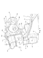
- Fig. 1 is a perspective view showing an overall vehicle body frame of a motorcycle according to an embodiment of the present invention.
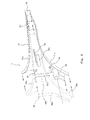
- Fig. 2 is a plan view showing the overall vehicle body frame when viewed from above.
- Fig. 3 is an enlarged perspective view showing a region surrounding a center cross member.
- Fig. 4 is a perspective view showing a cross-section of a structure for joining the center cross member to a lumber frame.
- Fig. 5 is a perspective view showing an internal structure of the lumber frame, from which a left steel plate is omitted.
- Fig. 6 is a perspective view showing a cross-section of the lumber frame taken along line VI-VI of Fig. 1 .
- Fig. 7 is a perspective view showing a cross-section of the lumber frame taken along line VII-VII of Fig. 1 .
- Fig. 8 is a perspective view showing a mounting state of a canister, and the like at a left side of the lumber frame.
- Fig. 9 is a perspective view showing a mounting state of an ABS unit at a right side of the lumber frame.
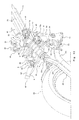
- Fig. 10 is a perspective view showing a mounting state of a suspension unit at the right side of the lumber frame.
- Fig. 1 is a perspective view showing an overall vehicle body frame 1.
- Fig. 2 is a plan view showing the overall vehicle body frame 1 when viewed from above. The stated directions are referenced from the perspective of a rider straddling the motorcycle.
- the vehicle body frame 1 of the motorcycle includes a head pipe 2 and a main frame 3 extending rearward from the head pipe 2 such that the main frame 3 is tilted in a slightly downward direction.
- the main frame 3 includes right and left frame members which are two members extending rearward from the head pipe 2.
- each of the right and left frame members includes two round pipes (hereinafter referred to as an upper main pipe 30 and a lower main pipe 31) arranged in a vertical direction.
- Rear ends of the right and left frame members are coupled together by means of a center cross member 4 (cross member) having a tubular shape with a rectangular cross-section and a small thickness.
- the rear ends of the right and left frame members are coupled to a lumber frame 5 in a rear frame portion via the center cross member 4.
- the main frame 3 is a backbone frame of a vehicle body.
- the right and left frame members are laid out with a certain distance between them, adaptively to an engine (not shown) positioned therebelow so that a good balance is easily attained between a bending stiffness and a twist stiffness.
- the lumber frame 5 is coupled to a rear end of the main frame 3 via the center cross member 4 and supports a swing arm 22 (see Fig. 10 ) of a rear wheel.
- the lumber frame 5 and the center cross member 4 constitute, for example, a lumber part of a frame. Therefore, the lumber frame 5 is referred to as the "lumber frame 5".
- the lumber frame 5 is composed of two steel plates 50 and 51 which are press-formed and joined together from a right side and a left side, and has a closed cross-section structure with a high stiffness.
- a fuel tank 20 is positioned above the main frame 3.
- a rear end portion of the fuel tank 20 extends rearward and downward and overlaps with a front end portion of the lumber frame 5.
- Behind the fuel tank 20, a seat 21 for two persons which is straddled by a rider or a tandem rider (not shown) is provided.
- a structure of a front frame portion including the head pipe 2, the main frame 3 and the center cross member 4 will be described.
- the head pipe 2 located in a forefront portion of the front frame portion is tilted in a rearward direction to allow a front wheel to have a desired caster angle.
- An upper portion of a front fork is coupled to a steering shaft inserted into the head pipe 2 via a pair of upper and lower brackets, although this is not shown. That is, the head pipe 2 constitutes a steering shaft of the front wheel of the motorcycle.
- Front end portions of the upper main pipes 30 of the main frame 3 are welded to an upper portion of the head pipe 2.
- Front end portions of the lower main frame pipes 31 of the main frame 3 are welded to a lower portion of the head pipe 2.
- the main pipes 30 extend rearward such that a distance between them in a rightward and leftward direction increases gradually, are curved inward in substantially center portions thereof, and then extend rearward such that a distance between them in the rightward leftward direction decreases gradually.
- the main pipes 31 extend rearward such that a distance between them in the rightward and leftward direction increases gradually, are curved inward in substantially center portions thereof, and then extend rearward such that a distance between them in the rightward leftward direction decreases gradually.
- a V-shaped gadget 33 extending from an outer periphery of the upper portion 30 of the head pipe 2 is joined to and welded to the front end portions of the upper main pipes such that the gadget 33 covers them from above.
- the gadget 33 is joined to and welded to the front end portions of the upper main pipes 30.
- a cross pipe 34 is positioned behind and adjacently to the gadget 33.
- the cross pipe 34 is provided between and coupled to the right and left upper main pipes 30.
- the cross pipe 34 is provided between and coupled to the right and left lower main pipes 31.
- a pillar 35 having a rectangular cross-section is provided to couple a center portion of the lower cross pipe 34 to a center portion of the upper cross pipe 34.
- the upper and lower cross pipes 34 and the pillar 35 coupling the upper and lower cross pipes 34 together reinforce a relatively front portion of the main frame 3 in which the distance between the right and left frame members (main pipes 30 and main pipes 31) in the rightward and leftward direction increases gradually in the rearward direction.
- down frames 36 extend downward from the right and left lower main pipes 31, respectively.
- the down frames 36 entirely have a T-shape.
- Insertion holes 36a of bolts fastened to a case of an engine are formed in a lower end portion of a downwardly extending portion of each of the down frames 36.
- An upper edge portion of each of the down frames 36 which extends in a substantially forward and rearward direction, is joined to a front portion of the corresponding lower main pipe 31 and is welded thereto linearly. This makes a welding work easier and provides an excellent external appearance of a welded portion, as compared to a case where the down frame 36 is welded to an entire outer periphery of the lower main pipe 31 which is a round pipe.
- the down frame 36 is composed of two steel plates which are press-formed and joined together from a right side and a left side, and has a closed cross-section structure.
- the down frame 36 can be manufactured at lower cost and can ensure a sufficient stiffness as compared to a down frame composed of a plurality of pipes combined together. Since the cross-section of the lumber frame 5 has a rectangular shape elongated in the forward and rearward direction, it can have a smaller width when viewed from a front, while ensuring a desired stiffness, which does not impede a flow of cooling air in a rearward direction. This has an advantage that a cooling capability of the engine is enhanced.
- Each of the down frames 36 is provided on an outer surface with a mount seat 36b of a cowl (not shown) and a mount seat 36c of a radiator (not shown).
- the mount seats are formed integrally with the outer steel plate when the outer steel plate is press-formed, and nuts are welded to reverse surfaces thereof to allow the cowl and the radiator to be easily mounted thereto.
- the mount seat is dented to conform in shape to a device such as the radiator, an increase in a vehicle width can be suppressed.
- This fitting structure of the dented portion and the corresponding protruding portion has an advantage that a stiffness of the frame is enhanced.
- plate-shaped brackets 37 are provided to couple the upper and lower pipes 30 and 31 of the right frame member (main pipes 30 and 31) of the main frame 3 together. These plate-shaped brackets 37 are respectively provided at corner portions of the right frame member from which the right frame member is curved inward, and relatively rear portions of the right frame member behind the corner portions, the relatively rear portions having a shape in which a distance in the rightward and leftward direction, with respect to corresponding rear portions of the left frame member, decreases in a rearward direction. Also, plate-shaped brackets 37 are provided to couple the upper and lower pipes 30 and 31 of the left frame member (main pipes 30 and 31) of the main frame 3 together.
- These plate-shaped brackets 37 are respectively provided at corner portions of the left frame member from which the left frame member is curved inward, and relatively rear portions of the left frame member behind the corner portions, the relatively rear portions having a shape in which a distance in the rightward and leftward direction, with respect to corresponding rear portions of the right frame member, decreases in a rearward direction.
- Rear ends of the upper and lower main pipes 30 and 31 are integrally coupled by joint members 38 and 39. Furthermore, the rear ends of the main pipes 30 and the main pipes 31 are further coupled together by means of the center cross member 4, as shown in Fig. 3 and 4 .
- the left joint member 38 depicted at a near side in Fig. 3 has a structure in which two end members 38a and 38b having a substantially cylindrical shape and having tapered fit-in portions at their tip ends are arranged at upper and lower sides and their base end portions are connected together.
- the fit-in portions of the end members 38a and 38b are fitted into the rear ends of the upper and lower main pipes 30 and 31, respectively, and are welded to an entire periphery of the main pipe 30 and an entire periphery of the main pipe 31, respectively.
- the right joint member 39 depicted at a far side in Fig. 3 couples upper and lower end members 39a and 39b together, like the left joint member 38.
- a suspension support portion 40 is integrally provided to extend from a location of a rear side of the upper end member 39a to an obliquely downward location.
- the right joint member 39 has a substantially cylindrical extending portion 39c extending from a location of a rear side of the lower end member 39b to the suspension support portion 40.
- the suspension support portion 40 includes a pair of right and left ring-shaped support plates 40a and 40b.
- the right support plate 40a is integral with the upper end member 39a of the joint member 39.
- the left support plate 40b is separate from the right support plate 40a such that the left support plate 40a is a predetermined distance apart from the right support plate 40b.
- a recess is provided to open leftward, i.e., outward in the vehicle width direction, at a base end side of the lower end member 38 of the left joint member 38.
- a recess is provided to open rightward, i.e., inward in the vehicle width direction, at a base end side of the upper end member 38a, although this is not shown.
- a recess is provided to open rightward, i.e., outward in the vehicle width direction, at a base end side of the lower end member 39b of the right joint member 39, while a recess is provided to open leftward, i.e., inward in the vehicle width direction, at a base end side of the upper end member 39a.
- the center cross member 4 couples the left joint member 38 and the right joint member 39 together at the rear end of the main frame 3.
- the center cross member 4 is configured in such a manner that two steel plates 41 and 42 press-formed are joined together in the forward and rearward direction, and a thick square pipe 43 (pipe member) is welded to a lower edge of the joined plates, to form a closed-cross section structure having a small thickness in the forward and rearward direction. Because of this structure, the center cross member 4 is allowed to have a high stiffness, and achieve space saving as compared to the pipe work. As a result, the fuel tank 20, and the device can be laid out flexibly in the vicinity of the center cross member 4.
- the center cross member 4 is placed to be tilted in a slightly forward direction.
- the joint members 38 and 39 are welded to left and right sides of an upper portion of the center cross member 4, while a front portion of the lumber frame 5 is welded to a substantially center portion of a rear surface of a lower portion of the center cross member 4.
- the fuel tank 20 is allowed to increase its volume.
- pipes, stays, and the like, constituting the vehicle body frame 1 are not present in this space, a mounting work of the devices such as a canister 7 can be performed easily as described later.
- the left joint member 38 and the right joint member 39 are provided with a swelling portion 38c and a swelling portion 39d, respectively.
- the swelling portions 38c and 39d are welded to the front and rear steel plates 41 and 42 of the center cross member 4 in a fitting state such that each of them is sandwiched between the front and rear steel plates 41 and 42.
- the swelling portion 38c of the left joint member 38 swells from the lower end member 38b, rightward, i.e., inward in the vehicle width direction toward the joint member 39, and extends to an underside of the lower end member 38b.
- the swelling portion 38c has a substantially-J shape.
- the swelling portion 39d of the right joint member 39 swells from the lower end member 39b to an obliquely downwardly extended portion 39c, leftward i.e., inward in the vehicle width direction toward the joint member 38, and extends to an underside of the extended portion 39c.
- the swelling portion 39d has a J-shape longer than that of the swelling portion 38c of the left joint member 38.
- the front steel plate 41 of the center cross member 4 basically has a substantially rectangular shape which is laterally elongated and has a rectangular hole 41a (shown in only in Fig. 4 ) in a center portion thereof.
- the rear steel plate 42 of the center cross member 4 basically has a substantially rectangular shape which is laterally elongated and has a rectangular hole 42a in a center portion thereof.
- the front steel plate 41 is provided with hollow portions 41b and 41c and the rear steel plate 42 is provided with hollow portions 42b and 42c on their right and left upper corner portions, to conform in shape to the end members 38b and 39b of the left and right joint members 38 and 39 and the extended portion 39c of the right joint member 39.
- a flange 41d is provided on an upper edge and right and left edges of the front steel plate 41 except for the hollow portions such that the flange 41d is bent rearward.
- a flange 42d is provided on an upper edge and right and left edges of the rear steel plate 42 except for the hollow portions such that the flange 42d is bent forward.
- an outer dimension of the front steel plate 41 is greater than an outer dimension of the rear steel plate 42.
- the flange 41d of the front steel plate 41 is joined to the flange 42d of the rear steel plate 42 from outside.
- a periphery of the outer flange 42d is welded substantially linearly to an outer peripheral surface of the inner flange 41d.
- Welded portions of the flanges 41d and 42d have a double structure and improve a stiffness.
- a weld material melts well in the welded portions and external appearance of the welded portions is excellent.
- the flanges 41d and 42d can be welded together linearly, and therefore a welding work is easy.
- the swelling portion 38c of the left joint member 38 is fitted into the opening.
- the swelling portion 39d of the right joint member 39 is fitted into the opening.
- the swelling portion 38c is fitted into the opening of the left upper portion of the front and rear steel plates 41 and 42 joined together
- the swelling portion 39d is fitted into the opening of the right upper portion the front and rear steel plates 41 and 42 joined together
- the swelling portions 38c and 39d are welded to peripheries of the openings, respectively.
- No flange is provided on lower edges of the front and rear steel plates 41 and 42.
- the lower edges of the front and rear steel plates 41 and 42 are joined and welded to an upper surface of a square pipe 43.
- the square pipe 43 has a greater thickness and a higher stiffness than the steel plates 41 and 42. Since the square pipe 43 is provided along the lower edges of the front and rear steel plates 41 and 42, a stiffness of the center cross member 4 is enhanced.
- a reinforcement tube 44 conforming in outer shape to the rectangular holes 41 a and 42a which are the openings in the center portions of the front and rear steel plates 41 and 42, respectively, is inserted into the rectangular holes 41 a and 42a. The reinforcement tube 44 penetrates the center cross member 4 in the forward and rearward direction and is welded to the center cross member 4.
- the reinforcement tube 44 has a tubular shape having a rectangular-cross section and a small thickness, which is formed by bending a band-shaped steel plate in its lengthwise direction. In the illustrated example, lengthwise both ends of the steel plates are abutted with each other and welded together in a center portion of an upper wall of the reinforcement tube 44.
- the stiffness of the center cross member 4 can be further enhanced. However, the outer dimension of the center cross member 4 remains unchanged, and therefore, the layout of the fuel tank 20 and the like and a mounting work of the devices are not negatively affected.
- the reinforcement tube 44 serves to reinforce the center cross member 4. However, the reinforcement tube 44 does not protrude outward from the center cross member 4 and does not interfere with components in the vicinity of the reinforcement tube 44, when these components are laid out.
- a harness or the like is inserted into the reinforcement tube 44 and hence penetrates the center cross member 4.
- a protruding portion 44a extending rearward (toward near side in the Figure) is provided on a lower wall of the reinforcement tube 44. As described later, an upward protruding portion 5a of a front edge of the lumber frame 5 is welded to the protruding portion 44a.
- the lumber frame 5 is welded to a lower portion of the center cross member 4 such that the lumber frame 5 orthogonally crosses the square pipe 43 when viewed from behind.
- a substantially-C-shaped hollow portion 5b is provided in an upper portion of a front edge of the lumber frame 5 to conform in shape from a rear surface of the rear steel plate 42 of the center cross member 4 to the square pipe 43 connected to the underside of the steel plate 42.
- the hollow portion 5b is joined to the square pipe 43 and to the rear surface of the steel plate 42.
- an upper surface of the lumber frame 5 extends upward in a forward direction.
- the lumber frame 5 has the upward protruding portion 5a protruding upward with an acute angle when viewed from a side.
- a front edge of the upward protruding portion 5a is an upper end portion of a front edge of the lumber frame 5.
- the front edge of the upward protruding portion 5a is joined to the rear surface of the rear steel plate 42 of the center cross member 42.
- the hollow portion 5b is continuous with an underside of the upward protruding portion 5a and extends from the upper surface of the square pipe 43, through the rear surface of the square pipe 43, and further to an underside of the square pipe 43, and retains the square pipe 43 from upper and lower sides.
- the square pipe 43 of the center cross member 4 is retained by and welded to the hollow portion 5b of the front edge of the lumber frame 5.
- the upward protruding portion 5a extending upward from the hollow portion 5b is welded in a state where it is retained between the upper surface of the square pipe 43 of the cross member 4 and the protruding portion 44a of the reinforcement tube 44 provided above the square pipe 43. That is, the center cross member 4 and the lumber frame 5 are welded together in a state where they are firmly fitted to each other by their concave-convex shape.
- wedge-shaped brackets 45 are provided from the rear surface of the square pipe 43 to right and left side surfaces of the lumber frame 5 behind the square pipe 43.
- the wedge-shaped brackets 45 are reinforcement plates having a double-walled structure and each has a right-triangle shape formed by bending a steel plate in the vertical direction.
- Each of right-angle portions of the brackets 45 is welded to a corner portion defined by the rear surface of the square pipe 43 and the front edge of the lumber frame 5. This can prevent the lumber frame 5 from being displaced in a rightward and leftward direction with respect to the rear surface of the center cross member 4. As a result, a more firmly joined state between the lumber frame 5 and the center cross member 4 is attained.
- plate-shaped engine brackets 46 and 47 (see Fig. 9 about engine bracket 47) extending forward from the front steel plate 41 to the square pipe 43 are provided on left and right portions of a lower portion of a front surface of the center cross member 4, respectively.
- the engine brackets 46 and 47 are fastened at right and left sides to an engine crankcase (not shown) and a transmission case (not shown) integral with the crankcase.
- the center cross member 4 having the closed cross-section structure with a small thickness in the forward and rearward direction couples the right and left frame members of the main frame 3 together, and couples them to the lumber frame 5 behind the right and left frame members. Therefore, a stiffness equal to or higher than a stiffness achieved by a general and conventional pipe work is attainable while achieving space saving. As a result, the fuel tank 20 and the devices can be laid out more flexibly.
- the rear end portion of the fuel tank 20 can be positioned in a location rearward and below relative to a rear end portion of a fuel tank in a conventional layout, in a space above the center cross member 4.
- the layout of the fuel tank 20 is not interfered by a cross pipe extending in the rightward and leftward direction, etc..
- the devices such as the canister 7 and the ABS unit 9 are laid out easily behind the center cross member 4, and a mounting work of the devices can be performed easily, which will be described in detail later.
- the seat 21 is allowed to have a sufficient thickness, which allows the rider to ride in the motorcycle comfortably.
- the lumber frame 5 includes a pivot frame section 5c extending downward from the center cross member 4 and a rear stay section 5d (forward portion of the rear frame portion) extending rearward from the center cross member 4 such that the pivot frame section 5c and the rear stay section 5d are integral with each other.
- a front end portion of a rear end frame 6 which is a rear portion of the rear frame portion is coupled to a rear end portion of the rear stay section 5d.
- an upper portion of a forward portion of the lumber frame 5 has an inverted-triangle shape which decreases its width in a downward direction when viewed from a side, and is tilted slightly forward in a downward direction, thus forming the pivot frame section 5c.
- the rear stay section 5d extends rearward in an obliquely upward direction from the inverted-triangle portion.
- the inverted-triangle portion is the forward portion of the rear stay section 5d and the upper portion of the pivot frame section 5c.
- the pivot frame section 5c has a circular hole in an intermediate portion in a vertical direction, to be precise, a portion slightly under a center portion.
- a pivot support tube 52 constituted by a round pipe is inserted into this hole and welded thereto.
- a lower cross pipe 53 constituted by a round pipe is welded to a lower end portion of the pivot frame section 5c and protrudes in the rightward and leftward direction.
- a right end surface of the lower cross pipe 53 conforms in position to a right side surface of the center cross member 4.
- a pivot plate 96 (see Fig. 10 ) is joined to the right end surface of the lower cross pipe 53.
- a side stand bracket 54 is mounted to a left end of the lower cross pipe 53.
- a mount seat of the pivot plate 96 is provided on a side stand bracket 54.
- a plate-shaped engine bracket 53a (see Fig. 9 ) extending forward is attached to a right portion of the lower cross pipe 53.
- a plate-shaped engine bracket 54a extending forward is attached to the side stand bracket 54.
- the engine brackets 53a and 54a are fastened at right and left sides to the transmission case.
- Muffler mounting brackets 55 are provided to extend rearward from the lower cross pipe 53 in a location corresponding to the right engine bracket 53a and in a location slightly rightward (inward in the vehicle width direction) relative to the left engine bracket 54a.
- the muffler mounting brackets 55 support a muffler in an exhaust system (not shown).
- the rear stay section 5d extending rearward and obliquely upward from the inverted-triangle portion of the upper half portion of the lumber frame 5 has a vertical width decreasing gradually in a rearward direction.
- a base portion of the rear stay section 5d is allowed to have a higher stiffness to withstand a weight of the rider or the tandem rider which is applied from the seat 21 placed on an upper portion of the rear stay section 5d.
- a lower surface of the rear stay section 5d is curved gradually in a downward direction in the inverted-triangle portion at a forward side thereof and is continuous with a rear surface of the pivot frame section 5c.
- a seat support 56 is provided in the vicinity of a center portion in the forward and rearward direction in the upper surface of the lumber frame 5 to support the seat 21 from below.
- the seat support 56 has an inverted-U shape formed by bending a steel plate.
- a left side plate of the seat support 56 is joined to a dented portion from a left side surface of the rear stay section 5d to an upper surface thereof.
- a mount seat 57 for the canister 7 and a mount seat 58 for a battery 8 are provided below the seat support 56.
- the lumber frame 5 including the pivot frame section 5c and the rear stay section 5d which are integral with each other has a closed cross-section structure in which the two press steel plates 50 and 51 are joined together from a right and from a left.
- the lumber frame 5 is configured to have a width as small as possible while ensuring a higher stiffness.
- the left steel plate 50 is indicated by an imaginary line and an interior of the right steel plate 51 is shown.
- the right steel plate 51 is provided with a flange 51a formed by bending the steel plate 51 inward, i.e., leftward in the vehicle width direction, in a substantially entire outer periphery of the right steel plate 51, i.e., a front edge of the pivot frame section 5c, a rear edge of the pivot frame section 5c, an upper edge of the rear stay section 5d and a lower edge of the rear stay section 5d.
- the left steel plate 50 is provided with a flange 50a formed by bending an outer periphery of the left steel plate 50.
- An outer dimension of the left steel plate 50 is smaller than an outer dimension of the right steel plate 51.
- the flange 51a of the right steel plate 51 is joined to an outer peripheral surface of the flange 50a of the left steel plate 50 from outside.
- the outer flange 51a is welded to the inner flange 50a substantially linearly along a periphery of the outer flange 51 a.
- each of a front surface of the pivot frame section 5c, an upper surface from an upper surface of the pivot frame section 5c to an upper surface of the rear stay section 5d, and a continuous surface from a rear surface of the pivot frame section 5c to a lower surface of the rear stay section 5d has a double-walled structure, to improve its stiffness. Since the surfaces are welded linearly along its lengthwise direction, a welding work is easy. In addition, a weld material melts well, and an external appearance of the welded portions is excellent. In particular, the upper surface applied with a lengthwise tensile stress due to a load from above has a sufficient weld strength which withstands a force for separating the welded portions from each other in the rightward and leftward direction.
- the stiffness of the lumber frame 5 having the closed cross-section structure can be adjusted depending on the thickness of the steel plates 50 and 51 instead of their cross-sectional areas and their cross-sectional shapes, or by providing a rib inside of the steel plates 50 and 51 as desired.
- a rib 59 is provided on an upper portion of the inverted-triangle portion of the pivot frame section 5c such that the rib 59 extends in a direction in which the rear stay section 5d extends.
- the rib 59 couples the right and left steel plates 50 and 51 together to prevent the rear stay section 5d from getting twisted or from getting separated in the rightward and leftward direction.
- the rib 59 is constituted by a plate member having a substantially rectangular shape elongated in the forward and rearward direction. A right edge of the plate member of the rib 59 is welded to a reverse surface of the right steel plate 51 (one of right and left plate members) such that the rib 59 protrudes leftward (toward the other side).
- the rib 59 has a bent portion 59a at a left end portion thereof by bending the plate member in a downward direction.
- the bent portion 59a is in contact with a reverse surface of a peripheral portion of the left steel plate 50 and is welded thereto to close an opening 50b formed in the left steel plate 50. In this structure, welding can be performed from an obverse surface side of the steel plate 50, i.e., from outside of the lumber frame 5, through the opening 50b.
- a rib 60 is provided to extend between the upper and lower flanges 51a of the right steel plate 51, and its upper edge and its lower edge are welded to the upper and lower flanges 51 a, respectively.
- front end portions of right and left pipes 61 of the rear end frame 6 are welded to the rear end portion of the rear stay section 5d, corresponding to the rib 60.
- the rib 60 reinforces this portion to withstand the weight of the tandem rider.
- a lid portion 62 is provided at a rear end of the rear stay section 5d to close its opening, thus effectively reinforcing a cross-section of the rear end of the rear stay section 5d.
- nuts 63 are welded in desired locations to the reverse surface of the right steel plate 51 of the lumber frame 5.
- bolts are threadingly engaged with the nuts 63 to mount an ABS unit 9 to the lumber frame 5.
- the steel plate 51 is provided with circular holes (not shown) into which the bolts are inserted, to correspond to the circular holes of the nuts 63, respectively.
- the lumber frame 5 When viewed from above with reference to Fig. 2 , the lumber frame 5 has a shape in which a width in the rightward and leftward direction is very small.
- the lumber frame 5 extends in the forward and rearward direction along a center line X of the vehicle body frame 1. At right and left sides of the lumber frame 5, spaces in which the devices are laid out are provided.
- a front end portion of the lumber frame 5 is located in a substantially center in the rightward and leftward direction.
- the ABS unit 9 is positioned in the space at the right side of the front end portion of the lumber frame 5.
- a portion of the lumber frame 5 which is behind its front end portion is deviated slightly rightward.
- the canister 7 and the battery 8 are laid out in an increased space at the left side of the deviated portion of the lumber frame 5.
- the width of the lumber frame 5 in the rightward and leftward direction is relatively great in a portion of the pivot frame section 5c which is under the pivot support tube 52.
- This portion has a square pipe portion in which a length in the forward and rearward direction is substantially equal to the width in the rightward and leftward direction.
- the pivot support tube 52 penetrates and is welded to an upper end portion of the square pipe portion.
- a lower end portion of the square pipe portion is welded to an outer periphery of the lower cross pipe 53. That is, a lower portion of the pivot frame section 5c which is applied with a great force from the rear wheel via the swing arm 22 is firmly reinforced.
- the lumber frame 5 has a region R (shown in only Figs. 6 and 7 ) in a location above the pivot support tube 52, which is a lower portion of the upper inverted-triangle shape and 1/3 of the upper inverted-triangle shape.
- the region R has a shape in which a length in the forward and rearward direction decreases gradually toward the pivot support tube 52 located below, and a width in the rightward and leftward direction increases gradually as the length decreases in a downward direction.
- Such a shape is intended to prevent a cross-sectional area of a horizontal cross-section of the pivot frame section 5c from changing rapidly in the vertical direction, to provide a stiffness.
- the left steel plate 50 is dented a little and the width of the lumber frame 5 in the rightward and leftward direction is slightly reduced.
- the rib 59 is provided obliquely rearward relative to the dented portion and in close proximity to the dented portion, to provide a sufficient stiffness.
- the dented portion is provided to correspond to a lower portion of the canister 7 laid out in the space at the left side of the lumber frame 5, the lower portion slightly swelling rightward.
- Fig. 8 shows a mounting structure of the canister 7 positioned at the left side of the lumber frame 5, in an enlarged manner.
- the lumber frame 5 is the reduced-width portion having the shape in which the width in the rightward and leftward direction is very small, in the overall vehicle body frame 1.
- the portion above the pivot support tube 52 has a smaller width in the rightward and leftward direction than a square pipe portion located thereunder.
- the canister 7 is positioned to correspond to this reduced-width portion, to temporarily store an evaporative fuel and purge the evaporative fuel.
- the canister 7 of a substantially rectangular box shape is laid out such that its lower edge is closer to an upper side of the pivot support tube 52 (i.e., its lower edge is positioned as low as possible) and the canister 7 is tilted in a rearward direction to avoid interference with the wedge-shaped bracket 45 for reinforcing the portion where the lumber frame 5 is joined to the center cross member 4.
- An upper surface of the canister 7 is located near the upper surface of the front portion of the lumber frame 5.
- a side surface and a lower surface of the canister 7 are surrounded by a metal-made holder 70.
- the holder 70 is fastened to the mount seat 57 of the lumber frame 5 by a bolt.
- the holder 70 is provided integrally with a support stay 70a for supporting a purge control valve 71 of the evaporative fuel.
- An introduction hose 72 for introducing the evaporative fuel from the fuel tank 20 into the canister 7 and a suction hose 73 for suctioning the evaporative fuel adsorbed onto active carbon in the canister 7 outward to the purge control valve 71 are coupled to an upper surface of the canister 7.
- the purge control valve 71 is coupled with an air-intake system of an engine, for example, a guide hose 74 for feeding the evaporative fuel to, for example, a throttle body.
- the guide hose 74 is inserted into the reinforcement tube 44 penetrating a substantially center portion of the center cross member 4.
- the hoses 71, 73 and 74 are applied with expensive fluorine coating. Since a rear end portion of the fuel tank 20 is positioned in close proximity to the canister 7 and immediately above the canister 7, the introduction hose 72 can be shortened in length, which results in reduced cost.
- a harness of CAN through which a control signal from an engine ECU is transmitted to the purge control valve 71, and through which a signal from a rear wheel vehicle speed sensor is transmitted to the engine ECU, a fuel hose, etc., are inserted into the reinforcement tube 44, although these are not shown.
- the canister 7 When the canister 7 is mounted to the lumber frame 5, the holder 70, and the purge control valve 71 are attached to the canister 7, and the hoses 71, 73, and 74 are coupled to the canister 7.
- An assembly of the canister 7 is temporarily placed in a predetermined location at the left side of the lumber frame 5, and then the holder 70 is fastened to the mount seat 57 by a bolt.
- the mount seat 57 is provided on the left steel plate 50 of the lumber frame 5, and the nut is welded to the mount seat 57, the bolt can be tightened more easily.
- the battery 8 is positioned behind the canister 7.
- the canister 7 is positioned in a forward region near the fuel tank 20 as described above, and the battery 8 is positioned behind and in close proximity to the canister 7.
- the battery 8 can be positioned as low as possible such that the battery 8 will not interfere with the swing arm 22.
- the battery 8 is placed on the mount seat 58 of an L-shape which is welded to a left side surface of the rear stay section 5d of the lumber frame 5.
- the battery 8 When viewed from the side, the battery 8 is placed such that its rear portion is slightly higher to substantially overlap with the rear stay section 5d extending upward in a rearward direction.
- This layout is preferable, because a cushion of the seat 21 placed above the battery 8 is allowed to have a substantial thickness, which allows the rider and the tandem rider to ride in the motorcycle comfortably.
- Fig. 9 shows a state where the ABS unit 9 is laid out at the right side of the lumber frame 5, in an enlarged manner, as in the case of Fig. 8 .
- the ABS unit 9 is intended to for ABS (anti-lock brake system) control in which, for example, a hydraulic brake pressure is reduced, to inhibit the wheels from being locked.
- a valve block 9a including a plurality of electromagnetic valves integrated together, a pump for increasing the hydraulic brake pressure, a drive motor 9b for actuating the pump, an ECU unit 9c for controlling the valve block 9a, the pump, and the drive motor 9b, and the like, are unitarily coupled together.
- the ABS unit 9 is mounted to the pivot frame section 5c of the lumber frame 5 such that the ABS unit 9 is positioned above and in close proximity to the pivot support tube 52, i.e., as low as possible.
- the ABS unit 9 is attached with a small projection (not shown) protruding upward along its left side surface (side surface at a far side in Fig. 9 ).
- the ABS unit 9 is fastened to a right side surface of the lumber frame 5 by a bolt penetrating the projection.
- a master cylinder 91 of a foot brake is positioned at a right side of the pivot frame section 5c. Since the ABS unit 9 is in close proximity to the master cylinder 91, brake pipes 92 coupling them together are short in length.
- the brake pipes 92 are coupled to an upper surface of the valve block 9a.
- Brake pipes 93 are laid out in the vicinity of the brake pipes 92 and are connected to a brake lever of the motorcycle or a wheel cylinder of a front wheel. Unlike the conventional general pipe frame, the brake pipes 93 need not be drawn to outside the pipes and the like, and are short in length. This has an advantage of cost reduction.
- a shield plate 94 is provided to surround the ABS unit 9 from three sides, which are a front surface of the ABS unit 9, a lower surface of the ABS unit 9, and a rear surface of the ABS unit 9, except for the upper surface to which the brake pipes 92 and 93 are attached.
- the shield plate 94 is formed by bending, for example, a rubber-made plate member.
- the shield plate 94 blocks heat radiated from the engine located forward, and protects the ABS unit 9 from water, mud, or stones, from forward, or from below.
- a socket of the ECU 9c is provided on a right side surface of the ABS unit 9. The harnesses through which signals are transmitted and received between vehicle speed sensors of the front wheel and the rear wheel, and the engine ECU, are inserted into the socket.
- the pivot plate 96 (see Fig. 10 ) is mounted from a right side to cover the harnesses. As a result, the ABS unit 9 is surrounded from all directions, except for from above.
- the pivot plate 96 covers pivot structure elements and the like, for supporting a front end portion of the swing arm 22. Therefore, a design cover is not required to cover the ABS unit 9 and the like.
- a reference symbol 95 designates a reserve tank of a brake fluid which is coupled to the master cylinder 91. A lid which is opened to fill the brake fluid for refill is attached on an upper portion of the reserve tank.
- the ABS unit 9 can be easily mounted to the lumber frame 5 from laterally.
- the pipes and the like of the vehicle body frame will not interfere with a mounting work of the ABS unit 9.
- An operator positions the ABS unit 9 within the shield plate 94, from the right side of the lumber frame 5, aligns the circular holes of the projections with respect to the circular holes of the right steel plate 51 of the lumber frame 5, inserts the bolts into these holes, and threadingly engages the bolts with the nuts 63 (see Fig. 5 ) welded to the reverse surface of the steel plate 51.
- a suspension unit 10 is positioned above the ABS unit 9.
- the swing arm 22 for supporting the rear wheel 23 (indicated by imaginary lines) is constituted by a pair of upper and lower round pipes 22a and 22b like the main frame 3 of the vehicle body.
- a front end portion of the lower round pipe 22b is supported by a shaft inserted into the pivot support tube 52, while a support portion 22c is provided at a front end portion of the upper round pipe 22a to support a lower end of the suspension unit 10.
- a substantially cylindrical oil damper 11 is provided with ring-shaped coupling portions 11a at upper and lower ends, and receivers 11b of a coil spring 12 which are welded to outer peripheries of the upper and lower ends of the oil damper 11, respectively.
- the coil spring 12 is wound around an outer periphery of the oil damper 11 such that the coil spring 12 is apart from the oil damper 11.
- the coil spring 12 is compressed preliminarily in a state where both ends of the spring 12 are in contact with the receivers 11b, respectively.
- the suspension unit 10 is located a predetermined distance above the ABS unit 9 such that the suspension unit 10 extends in the forward and rearward direction and is tilted upward in a forward direction.
- the coupling portion 11a at the upper end of the suspension unit 10 is rotatably supported by a suspension support unit 40 at a rear end of the main frame 3.
- the ring-shaped coupling portion 11a at the upper end of the oil damper 11 is rotatably coupled by a coupling shaft piercing a left support plate 40a and a right support plate 40b of the suspension support unit 40 in a state where the coupling portion 11a is sandwiched between the left support plate 40a and the right support plate 40b.
- the coupling portion 11a at the lower end portion of the suspension unit 10 is rotatably coupled to the support portion 22c at a front end of the swing arm 22.
- the suspension unit 10 is positioned such that it is deviated rightward from the lumber frame 5 extending through a substantially center portion of the vehicle body. As shown in Fig. 10 , the layout of the suspension unit 10 allows the main frame 3 extending downward in a rearward direction to be smoothly continuous with the swing arm 22 behind the main frame 3. Thus, an external appearance of the motorcycle is enhanced.
- the main frame 3 of the front frame portion to which the engine and the transmission are mounted includes a pair of right and left frame members (upper and lower main pipes 30 and 31) like a conventional configuration, but a relatively forward portion of the rear frame portion which is continuous with the rear portion of the main frame 3 is constituted by the lumber frame 5 extending through a substantially center portion of the vehicle body and having a small width in the rightward and leftward direction.
- the devices such as the canister 7, the ABS unit 9, and the like are laid out, and are easily mounted to the vehicle body frame 1 from the right side and from the left side.
- the lumber frame 5 having a small width in the rightward and leftward direction has the closed cross-section structure in which the press steel plates 50 and 51 are joined together from the right and from the left.
- the lumber frame 5 can have an appropriate cross-sectional coefficient by setting its shape or the like.
- the lumber frame 5 can have a sufficient stiffness regardless of its small width.
- the vehicle body frame 1 can reduce cost and achieve a good weld property as compared to a vehicle body frame of a pipe work.
- the vehicle body frame 1 has an advantage in stiffness.
- the left and right steel plates 50 and 51 constituting the lumber frame 5 having the closed cross-section structure can be integrally molded by pressing or the like. This has an advantage of reduction of manufacturing cost.
- the mount seats are provided on the steel plates 50 and 51, and the nuts and the like are welded to the reverse surfaces of the steel plates 50 and 51. This makes it easier to mount the devices to the vehicle body frame 1.
- the center cross member 4 coupling the rear ends of the right and left frame members of the main frame 3 has the closed cross-section structure in which the steel plates 41 and 42 are joined together in the forward and rearward direction. Therefore, the center cross member 4 has a stiffness equal to or higher than that of the vehicle body frame of the conventional general pipe work, while achieving low cost and space saving. This has an advantage that the devices are laid out and mounted easily.
- the rear end portion of the fuel tank 20 is positioned in a space from a location above the center cross member 4 to a location behind the center cross member 4, and is behind and below a rear portion of a fuel tank positioned with respect to the conventional vehicle body frame. This makes it possible to achieve a good weight balance of the vehicle.
- the lumber frame 5 is welded to the rear surface of the steel plate 42 and to the square pipe 43 in the center cross member 4, from behind, the upward protruding portion 5a at the front end of the lumber frame 5 is welded to the reinforcement tube 44 of the center cross member 4, and the wedge-shaped bracket 45 is provided between the lumber frame 5 and the square pipe 43, thereby enhancing a joint stiffness.
- the center cross member 4 is provided with the engine brackets 46 and 47 and the pivot frame section 5c of the lumber frame 5 is provided with the engine brackets 53a and 54a so that the center cross member 4 and the lumber frame 5 are joined together with an improved stiffness, by joining them to the engine case.
- the plurality of devices can be laid out without a wasted space according to the sizes and shapes of the devices.
- the ABS unit is positioned in a lower location, at the right side of the lumber frame 5, and the suspension unit 10 is positioned above the ABS unit, while the canister 7 is positioned near the fuel tank 20 at the left side of the lumber frame 5, and the battery 8 is positioned behind the canister 7 as low as possible.
- the layout of all of the canister 7, the battery 8, the ABS unit 9, and the suspension unit 10 in the vicinity of the lumber frame 5 is optimized, and the vehicle width does not increase substantially, even though many devices are laid out in the vicinity of the seat 21. Therefore, the leg portions of the rider fit the seat 21 well, and the rider can feel unity with the motorcycle. The rider can ride in the motorcycle more comfortably, and can rest feet on the ground more comfortably.
- the pivot frame section 5c and the rear stay section 5d are integral with each other to form the lumber frame 5 having the closed cross-section structure in the rear portion of the vehicle body frame 1.
- the present invention is not limited to this, but only either one of the pivot frame section 5c and the rear stay section 5d may have the closed cross-section structure and may be welded to the center cross member 4.
- both of the center cross member 4 and the lumber frame 5 have the closed cross-section structures.
- the center cross member 4 need not have the closed cross-section structure, but may have a structure of the conventional pipe work.
- the lumber frame 5 need not have the closed cross-section structure, but may be constituted by a square pipe, or the like, so long as the lumber frame 5 having a smaller width in the rightward and leftward direction can ensure a stiffness.
- the canister 7, the battery 8, the ABS unit 9, and the suspension unit 10 are illustrated as the devices incorporated into the motorcycle, the devices are not limited to these, but may be, for example, a GPS unit, a relay box, a regulator, an ECU, or the like.
- the devices incorporated into the motorcycle for the purpose of safety or emission regulation can be laid out easily while ensuring a stiffness of the vehicle body frame, and can be mounted to the vehicle body frame easily and efficiently. Therefore, the present invention is widely and effectively applied to a motorcycle which can achieve beneficial effects of the present invention.
Abstract
Description
- The present invention relates to a motorcycle. Particularly, the present invention relates to a mounting structure of devices incorporated into the motorcycle, such as an ABS unit, a canister, and a battery.
- Conventionally, in a vehicle body frame of a motorcycle, a pivot frame unit extending downward is typically coupled to a rear end of a main frame unit extending rearward and obliquely downward from a head pipe. Typically, below the main frame unit, an engine, a transmission, and others are laid out. Therefore, the main frame unit is commonly composed of a pair of right and left main frame members which are spaced apart from each other. For example, Japanese Laid-Open Patent Application Publication No.
2010-058763 - Rear arm brackets (pivot frame unit) are welded to the right and left pipes of the pipe frame, respectively, such that the rear arm brackets extend downward from substantially center portions of the right and left pipes in a forward and rearward direction. Pivots are attached to the rear arm brackets, respectively, and front ends of rear arms (swing arms) are supported by the pivots such that the rear arms are pivotable around the pivots. A rear frame unit is constructed in such a manner that rear ends of back stays extending rearward and obliquely upward from portions of the right and left rear arm brackets are welded to the rear ends of the right and left pipes of the pipe frame, respectively.
- In recent years, to improve safety, to meet emission regulation, etc., devices incorporated into a motorcycle, for example, an ABS unit, a GPS unit, and a canister of an evaporative fuel, has been increasing in number. Therefore, an attention has been paid to a space in which these devices are laid out. For example, Japanese Laid-Open Patent Application Publication No.
2009-292350 - However, in a case where the ABS unit is laid out near the right and left rear arm brackets like the latter conventional example, pipes, stays, and others constituting a vehicle body frame, such as the right and left pipes of the pipe frame, the rear arm brackets, a cross pipe, and back stays, surround the ABS unit from above and from right and left sides. Therefore, it is very difficult to mount the ABS unit to the vehicle body.
- To be specific, when the ABS unit is laid out in a space between the pipes and others surrounding the ABS unit, and bolts and nuts are tightened, interference with the surrounding pipes and others tends to occur. In addition, when a brake pipe is attached to the ABS unit mounted in this way, interference with the pipes and others is unavoidable. Furthermore, since a metal-made pipe must be drawn to outside the pipes and the like of the frame, its length tends to be great, an assembling work becomes difficult and inefficient, and manufacturing cost increases.
- Since the plurality of pipes and the like are combined three-dimensionally to provide a stiffness of the overall frame, it is very difficult to modify the layout of the pipes to widen a mounting space for the devices. Thus, in principle, it is necessary to ensure the mounting space between determined pipe works. If the pipes and the like are provided with a dented portion or a hollow portion to avoid interference with the devices, their stiffness may possibly decrease significantly due to concentration of a stress.
- In general, a dimension of the space between determined pipe works does not conform to an outer dimension of the device. When the device is laid out in this space, a wasted space tends to increase. With an increase in the number of the devices, a vehicle width will inevitably increase. If this happens near a seat, a rider cannot fit leg portions to the seat suitably, and cannot attain unity with the motorcycle. Furthermore, it is difficult to ensure a substantial thickness of the seat depending on a balance with the height of the seat. That is, it is difficult to allow a rider to put the rider's feet on the ground comfortably while sitting on the seat comfortably.
- The present invention addresses the above described conditions, and an object of the present invention is to devise a layout of devices incorporated into a motorcycle to ensure a mounting space for a plurality of devices and to easily mount the devices without increasing a vehicle width undesirably.
- To achieve the above described object, the present invention relates to a mounting structure for mounting a device incorporated into the motorcycle and mounted to a vehicle body frame including a front frame portion extending rearward from a head pipe and a rear frame portion extending rearward from a rear end of the front frame portion. A forward portion of the rear frame portion includes a reduced-width portion overlapping with a vehicle body center line extending in a forward and rearward direction when viewed from above, and having a shape in which a width in a rightward and leftward direction is smaller than a length in an upward and downward direction. The device is laid out in a space lateral relative to the reduced-width portion. The phrase the forward portion of the rear frame portion "overlaps with" the vehicle body center line when viewed from above means that at least a portion of the forward portion overlaps with the vehicle body center line, and does not mean that the forward portion entirely overlaps with the vehicle body center line in the forward and rearward direction.
- In accordance with the above configuration, the forward portion of the rear frame portion in the vehicle body frame of the motorcycle is positioned in the vicinity of a center in a vehicle width direction and includes the reduced-width portion in which the width in the rightward and leftward direction is smaller. Therefore, spaces in which the devices are laid out can be provided at right and left sides of the reduced-width portion. Exemplary devices incorporated into the motorcycle are an ABS unit, a GPS unit, a canister, a battery, a suspension unit, etc.. Since these devices can be mounted to the vehicle body frame from the right and left sides, interference with pipes and the like, which tends to occur in a conventional vehicle body frame, will not occur.
- Since continuous spaces which are not interfered by the pipes and the like can be provided at the right and left sides of the reduced-width portion, respectively, necessary mounting spaces can be set without a wasted space, according to sizes and shapes of the devices laid out in these spaces. Therefore, even when the devices to be laid out increase in number, the vehicle width does not increase undesirably.
- That is, a wasted space in the rear portion of the vehicle body frame of the motorcycle can be lessened, the vehicle width does not increase undesirably, and a mounting work of these devices can be performed easily. Since a plurality of devices can be laid out without a wasted space, a distance between these devices is smaller, and various members such as a harness, a cable, and a hose for coupling these devices can be made short in length. This also results in reduced cost, and may possibly provide an extra space.
- When the rear frame portion includes the rear frame section extending rearward from the rear end of the front frame portion and the pivot frame section extending downward from the rear end of the front frame portion, preferably, an upper portion of the pivot frame section and a forward portion of the rear frame section may be integral with each other to form the reduced-width portion. Thus, since the integral reduced-width portion extends over a wide range of the vehicle body frame, more devices can be laid out, and manufacturing cost can be reduced.
- Preferably, the reduced-width portion has a closed-cross section structure in which plate members are joined together from a right side and a left side. This allows the reduced-with portion to have a desired stiffness easily. The stiffness of the closed cross-section structure can be changed depending on the material or thickness of the plate material as well as its cross-sectional area or cross-sectional shape, and can be adjusted by adding a rib to inside thereof. Therefore, it is less likely that the width in the rightward and leftward direction increases for ensuring a stiffness. In addition, by providing mount seats of the devices to the plate members joined together or welding bolts, nuts, and others to the plate members, the devices can be mounted to the vehicle body frame more easily.
- The forward portion of the rear frame portion has a smaller width to ensure the mounting spaces for the devices as described above, while the width of the pair of right and left frame members in the front frame portion may be set to correspond to an engine, a transmission, etc., like the conventional vehicle body frame. Thus, the width of the reduced-width portion in the rightward and leftward direction is smaller than a distance between rear end portions of the right and left frame members.
- As the devices incorporated into the motorcycle, specifically, an ABS unit is preferably positioned at a right side of the reduced-width portion of the vehicle body frame. The reason is as follows. Since a brake cylinder of a foot brake is positioned at a right side of the vehicle body frame, a brake pipe can be made short in length by positioning the ABS unit near the brake cylinder.
- The canister and the battery may be laid out either at the right side or the left side of the reduced-width portion. Preferably, the canister of an evaporative fuel is positioned near the fuel tank. So, if the canister and the battery are laid out at the same side, it is preferable that the canister is positioned in a relatively forward region, and the battery is positioned in a relatively rearward region. Unlike the conventional vehicle body frame,
it is less likely that the pipes and the like of the vehicle body frame interferes with the battery. Therefore, the battery can be positioned as low as possible to a location where the battery does not contact a swing arm. With this layout, the seat is configured to have a substantial thickness so that a rider can ride the motorcycle comfortably, or the seat is configured to have a small height so that the rider can rest feet on a ground comfortably. Because of a reduced vehicle width, the rider can rest feet on the ground very comfortably. - Moreover, a suspension unit can be positioned at the right side or at the left side of the reduced-width portion extending a substantially center in the rightward and leftward direction such that the suspension unit is deviated from the reduced-width portion. For example, the suspension unit may be laid out such that the suspension unit extends in the forward and rearward direction between a main frame and the swing arm and is tilted in a forward direction. When the ABS unit is positioned at the right side of the reduced-width portion, the canister may be positioned in a forward region at the left side of the reduced-width portion, and the battery may be positioned behind the canister, while the suspension unit may be positioned above the ABS unit at the right side of the reduced-width portion such that the suspension unit extends in the forward and rearward direction.
- The above and further objects, features and advantages of the invention will more fully be apparent from the following detailed description with reference to the accompanying drawings.
-
Fig. 1 is a perspective view showing an overall vehicle body frame of a motorcycle according to an embodiment of the present invention. -
Fig. 2 is a plan view showing the overall vehicle body frame when viewed from above. -
Fig. 3 is an enlarged perspective view showing a region surrounding a center cross member. -
Fig. 4 is a perspective view showing a cross-section of a structure for joining the center cross member to a lumber frame. -
Fig. 5 is a perspective view showing an internal structure of the lumber frame, from which a left steel plate is omitted. -
Fig. 6 is a perspective view showing a cross-section of the lumber frame taken along line VI-VI ofFig. 1 . -
Fig. 7 is a perspective view showing a cross-section of the lumber frame taken along line VII-VII ofFig. 1 . -
Fig. 8 is a perspective view showing a mounting state of a canister, and the like at a left side of the lumber frame. -
Fig. 9 is a perspective view showing a mounting state of an ABS unit at a right side of the lumber frame. -
Fig. 10 is a perspective view showing a mounting state of a suspension unit at the right side of the lumber frame. - Now, a vehicle body frame of a motorcycle according to an embodiment of the present invention will be described with reference to the drawings.
Fig. 1 is a perspective view showing an overallvehicle body frame 1.Fig. 2 is a plan view showing the overallvehicle body frame 1 when viewed from above. The stated directions are referenced from the perspective of a rider straddling the motorcycle. - As shown in
Figs. 1 and2 , thevehicle body frame 1 of the motorcycle includes ahead pipe 2 and amain frame 3 extending rearward from thehead pipe 2 such that themain frame 3 is tilted in a slightly downward direction. Themain frame 3 includes right and left frame members which are two members extending rearward from thehead pipe 2. In this example, each of the right and left frame members includes two round pipes (hereinafter referred to as an uppermain pipe 30 and a lower main pipe 31) arranged in a vertical direction. Rear ends of the right and left frame members are coupled together by means of a center cross member 4 (cross member) having a tubular shape with a rectangular cross-section and a small thickness. The rear ends of the right and left frame members are coupled to alumber frame 5 in a rear frame portion via thecenter cross member 4. - The
main frame 3 is a backbone frame of a vehicle body. The right and left frame members are laid out with a certain distance between them, adaptively to an engine (not shown) positioned therebelow so that a good balance is easily attained between a bending stiffness and a twist stiffness. Thelumber frame 5 is coupled to a rear end of themain frame 3 via thecenter cross member 4 and supports a swing arm 22 (seeFig. 10 ) of a rear wheel. Thelumber frame 5 and thecenter cross member 4 constitute, for example, a lumber part of a frame. Therefore, thelumber frame 5 is referred to as the "lumber frame 5". As will be described in detail later, thelumber frame 5 is composed of twosteel plates - As schematically indicated by an imaginary line in
Fig. 1 , afuel tank 20 is positioned above themain frame 3. A rear end portion of thefuel tank 20 extends rearward and downward and overlaps with a front end portion of thelumber frame 5. Behind thefuel tank 20, aseat 21 for two persons which is straddled by a rider or a tandem rider (not shown) is provided. - A structure of a front frame portion including the
head pipe 2, themain frame 3 and thecenter cross member 4 will be described. Thehead pipe 2 located in a forefront portion of the front frame portion is tilted in a rearward direction to allow a front wheel to have a desired caster angle. An upper portion of a front fork is coupled to a steering shaft inserted into thehead pipe 2 via a pair of upper and lower brackets, although this is not shown. That is, thehead pipe 2 constitutes a steering shaft of the front wheel of the motorcycle. - Front end portions of the upper
main pipes 30 of themain frame 3 are welded to an upper portion of thehead pipe 2. Front end portions of the lowermain frame pipes 31 of themain frame 3 are welded to a lower portion of thehead pipe 2. As can be seen fromFig. 2 , themain pipes 30 extend rearward such that a distance between them in a rightward and leftward direction increases gradually, are curved inward in substantially center portions thereof, and then extend rearward such that a distance between them in the rightward leftward direction decreases gradually. Themain pipes 31 extend rearward such that a distance between them in the rightward and leftward direction increases gradually, are curved inward in substantially center portions thereof, and then extend rearward such that a distance between them in the rightward leftward direction decreases gradually. A V-shapedgadget 33 extending from an outer periphery of theupper portion 30 of thehead pipe 2 is joined to and welded to the front end portions of the upper main pipes such that thegadget 33 covers them from above. Thegadget 33 is joined to and welded to the front end portions of the uppermain pipes 30. Across pipe 34 is positioned behind and adjacently to thegadget 33. Thecross pipe 34 is provided between and coupled to the right and left uppermain pipes 30. - Likewise, the
cross pipe 34 is provided between and coupled to the right and left lowermain pipes 31. Apillar 35 having a rectangular cross-section is provided to couple a center portion of thelower cross pipe 34 to a center portion of theupper cross pipe 34. In other words, the upper andlower cross pipes 34 and thepillar 35 coupling the upper andlower cross pipes 34 together reinforce a relatively front portion of themain frame 3 in which the distance between the right and left frame members (main pipes 30 and main pipes 31) in the rightward and leftward direction increases gradually in the rearward direction. - In the forward portion of the
main frame 3 which is reinforced to have a higher stiffness, down frames 36 extend downward from the right and left lowermain pipes 31, respectively. The down frames 36 entirely have a T-shape.Insertion holes 36a of bolts fastened to a case of an engine are formed in a lower end portion of a downwardly extending portion of each of the down frames 36. An upper edge portion of each of the down frames 36, which extends in a substantially forward and rearward direction, is joined to a front portion of the corresponding lowermain pipe 31 and is welded thereto linearly. This makes a welding work easier and provides an excellent external appearance of a welded portion, as compared to a case where thedown frame 36 is welded to an entire outer periphery of the lowermain pipe 31 which is a round pipe. - In this example, like the
lumber frame 5, thedown frame 36 is composed of two steel plates which are press-formed and joined together from a right side and a left side, and has a closed cross-section structure. The downframe 36 can be manufactured at lower cost and can ensure a sufficient stiffness as compared to a down frame composed of a plurality of pipes combined together. Since the cross-section of thelumber frame 5 has a rectangular shape elongated in the forward and rearward direction, it can have a smaller width when viewed from a front, while ensuring a desired stiffness, which does not impede a flow of cooling air in a rearward direction. This has an advantage that a cooling capability of the engine is enhanced. - Each of the down frames 36 is provided on an outer surface with a
mount seat 36b of a cowl (not shown) and amount seat 36c of a radiator (not shown). The mount seats are formed integrally with the outer steel plate when the outer steel plate is press-formed, and nuts are welded to reverse surfaces thereof to allow the cowl and the radiator to be easily mounted thereto. In that case, if the mount seat is dented to conform in shape to a device such as the radiator, an increase in a vehicle width can be suppressed. This fitting structure of the dented portion and the corresponding protruding portion has an advantage that a stiffness of the frame is enhanced. - Furthermore, plate-shaped
brackets 37 are provided to couple the upper andlower pipes main pipes 30 and 31) of themain frame 3 together. These plate-shapedbrackets 37 are respectively provided at corner portions of the right frame member from which the right frame member is curved inward, and relatively rear portions of the right frame member behind the corner portions, the relatively rear portions having a shape in which a distance in the rightward and leftward direction, with respect to corresponding rear portions of the left frame member, decreases in a rearward direction. Also, plate-shapedbrackets 37 are provided to couple the upper andlower pipes main pipes 30 and 31) of themain frame 3 together. These plate-shapedbrackets 37 are respectively provided at corner portions of the left frame member from which the left frame member is curved inward, and relatively rear portions of the left frame member behind the corner portions, the relatively rear portions having a shape in which a distance in the rightward and leftward direction, with respect to corresponding rear portions of the right frame member, decreases in a rearward direction. - Rear ends of the upper and lower
main pipes joint members main pipes 30 and themain pipes 31 are further coupled together by means of thecenter cross member 4, as shown inFig. 3 and4 . As shown inFig. 3 , the leftjoint member 38 depicted at a near side inFig. 3 has a structure in which twoend members end members main pipes main pipe 30 and an entire periphery of themain pipe 31, respectively. - The right
joint member 39 depicted at a far side inFig. 3 couples upper andlower end members joint member 38. Asuspension support portion 40 is integrally provided to extend from a location of a rear side of theupper end member 39a to an obliquely downward location. Furthermore, the rightjoint member 39 has a substantially cylindrical extendingportion 39c extending from a location of a rear side of thelower end member 39b to thesuspension support portion 40. Thesuspension support portion 40 includes a pair of right and left ring-shapedsupport plates right support plate 40a is integral with theupper end member 39a of thejoint member 39. Theleft support plate 40b is separate from theright support plate 40a such that theleft support plate 40a is a predetermined distance apart from theright support plate 40b. - As can be seen from
Fig. 3 , a recess is provided to open leftward, i.e., outward in the vehicle width direction, at a base end side of thelower end member 38 of the leftjoint member 38. A recess is provided to open rightward, i.e., inward in the vehicle width direction, at a base end side of theupper end member 38a, although this is not shown. In the same manner, a recess is provided to open rightward, i.e., outward in the vehicle width direction, at a base end side of thelower end member 39b of the rightjoint member 39, while a recess is provided to open leftward, i.e., inward in the vehicle width direction, at a base end side of theupper end member 39a. - The
center cross member 4 couples the leftjoint member 38 and the rightjoint member 39 together at the rear end of themain frame 3. As described below, thecenter cross member 4 is configured in such a manner that twosteel plates center cross member 4 is allowed to have a high stiffness, and achieve space saving as compared to the pipe work. As a result, thefuel tank 20, and the device can be laid out flexibly in the vicinity of thecenter cross member 4. - To be specific, the
center cross member 4 is placed to be tilted in a slightly forward direction. Thejoint members center cross member 4, while a front portion of thelumber frame 5 is welded to a substantially center portion of a rear surface of a lower portion of thecenter cross member 4. In this layout, since a rear end of thefuel tank 20 can be extended downward to a space from a location above thecenter cross member 4 to a location rearward or obliquely rearward relative to thecenter cross member 4, thefuel tank 20 is allowed to increase its volume. In addition, since pipes, stays, and the like, constituting thevehicle body frame 1 are not present in this space, a mounting work of the devices such as acanister 7 can be performed easily as described later. - To be more specific, as indicated by a broken line in
Fig. 3 , the leftjoint member 38 and the rightjoint member 39 are provided with a swellingportion 38c and a swellingportion 39d, respectively. The swellingportions rear steel plates center cross member 4 in a fitting state such that each of them is sandwiched between the front andrear steel plates portion 38c of the leftjoint member 38 swells from thelower end member 38b, rightward, i.e., inward in the vehicle width direction toward thejoint member 39, and extends to an underside of thelower end member 38b. Thus, the swellingportion 38c has a substantially-J shape. - The swelling
portion 39d of the rightjoint member 39 swells from thelower end member 39b to an obliquely downwardly extendedportion 39c, leftward i.e., inward in the vehicle width direction toward thejoint member 38, and extends to an underside of theextended portion 39c. Thus, the swellingportion 39d has a J-shape longer than that of the swellingportion 38c of the leftjoint member 38. - The
front steel plate 41 of thecenter cross member 4 basically has a substantially rectangular shape which is laterally elongated and has arectangular hole 41a (shown in only inFig. 4 ) in a center portion thereof. Therear steel plate 42 of thecenter cross member 4 basically has a substantially rectangular shape which is laterally elongated and has arectangular hole 42a in a center portion thereof. Thefront steel plate 41 is provided withhollow portions rear steel plate 42 is provided withhollow portions end members joint members extended portion 39c of the rightjoint member 39. Aflange 41d is provided on an upper edge and right and left edges of thefront steel plate 41 except for the hollow portions such that theflange 41d is bent rearward. Aflange 42d is provided on an upper edge and right and left edges of therear steel plate 42 except for the hollow portions such that theflange 42d is bent forward. - In the illustrated example, an outer dimension of the
front steel plate 41 is greater than an outer dimension of therear steel plate 42. As can be seen fromFig. 4 , in a state where thefront steel plate 41 and therear steel plate 42 are joined together in the forward and rearward direction, theflange 41d of thefront steel plate 41 is joined to theflange 42d of therear steel plate 42 from outside. In this state, a periphery of theouter flange 42d is welded substantially linearly to an outer peripheral surface of theinner flange 41d. Welded portions of theflanges flanges - In a state where the
front steel plate 41 and therear steel plate 42 are joined together and coupled unitarily, and thehollow portions steel plates portion 38c of the leftjoint member 38 is fitted into the opening. In the same manner, in a state where thefront steel plate 41 and therear steel plate 42 are unitarily joined together, and thehollow portions steel plates portion 39d of the rightjoint member 39 is fitted into the opening. In this way, the swellingportion 38c is fitted into the opening of the left upper portion of the front andrear steel plates portion 39d is fitted into the opening of the right upper portion the front andrear steel plates portions - No flange is provided on lower edges of the front and
rear steel plates rear steel plates square pipe 43. Thesquare pipe 43 has a greater thickness and a higher stiffness than thesteel plates square pipe 43 is provided along the lower edges of the front andrear steel plates center cross member 4 is enhanced. Moreover, a reinforcement tube 44 (reinforcement member) conforming in outer shape to therectangular holes rear steel plates rectangular holes reinforcement tube 44 penetrates thecenter cross member 4 in the forward and rearward direction and is welded to thecenter cross member 4. - The
reinforcement tube 44 has a tubular shape having a rectangular-cross section and a small thickness, which is formed by bending a band-shaped steel plate in its lengthwise direction. In the illustrated example, lengthwise both ends of the steel plates are abutted with each other and welded together in a center portion of an upper wall of thereinforcement tube 44. By addition of thereinforcement tube 44, the stiffness of thecenter cross member 4 can be further enhanced. However, the outer dimension of thecenter cross member 4 remains unchanged, and therefore, the layout of thefuel tank 20 and the like and a mounting work of the devices are not negatively affected. - In brief, the
reinforcement tube 44 serves to reinforce thecenter cross member 4. However, thereinforcement tube 44 does not protrude outward from thecenter cross member 4 and does not interfere with components in the vicinity of thereinforcement tube 44, when these components are laid out. In addition, as described later, a harness or the like is inserted into thereinforcement tube 44 and hence penetrates thecenter cross member 4. Thus, a layout of electric components and a length of the harness can be optimized. A protrudingportion 44a extending rearward (toward near side in the Figure) is provided on a lower wall of thereinforcement tube 44. As described later, an upward protrudingportion 5a of a front edge of thelumber frame 5 is welded to the protrudingportion 44a. - A detailed structure of the
lumber frame 5 will be described later. As can be seen fromFigs. 3 and4 , thelumber frame 5 is welded to a lower portion of thecenter cross member 4 such that thelumber frame 5 orthogonally crosses thesquare pipe 43 when viewed from behind. A substantially-C-shapedhollow portion 5b is provided in an upper portion of a front edge of thelumber frame 5 to conform in shape from a rear surface of therear steel plate 42 of thecenter cross member 4 to thesquare pipe 43 connected to the underside of thesteel plate 42. Thehollow portion 5b is joined to thesquare pipe 43 and to the rear surface of thesteel plate 42. - To be more specific, an upper surface of the
lumber frame 5 extends upward in a forward direction. Thelumber frame 5 has the upward protrudingportion 5a protruding upward with an acute angle when viewed from a side. A front edge of the upward protrudingportion 5a is an upper end portion of a front edge of thelumber frame 5. As can be seen fromFigs. 3 and4 , the front edge of the upward protrudingportion 5a is joined to the rear surface of therear steel plate 42 of thecenter cross member 42. Thehollow portion 5b is continuous with an underside of the upward protrudingportion 5a and extends from the upper surface of thesquare pipe 43, through the rear surface of thesquare pipe 43, and further to an underside of thesquare pipe 43, and retains thesquare pipe 43 from upper and lower sides. - Thus, the
square pipe 43 of thecenter cross member 4 is retained by and welded to thehollow portion 5b of the front edge of thelumber frame 5. And, the upward protrudingportion 5a extending upward from thehollow portion 5b is welded in a state where it is retained between the upper surface of thesquare pipe 43 of thecross member 4 and the protrudingportion 44a of thereinforcement tube 44 provided above thesquare pipe 43. That is, thecenter cross member 4 and thelumber frame 5 are welded together in a state where they are firmly fitted to each other by their concave-convex shape. - Furthermore, between the
square pipe 43 and thelumber frame 5 joined together in a cross shape as described above, wedge-shapedbrackets 45 are provided from the rear surface of thesquare pipe 43 to right and left side surfaces of thelumber frame 5 behind thesquare pipe 43. The wedge-shapedbrackets 45 are reinforcement plates having a double-walled structure and each has a right-triangle shape formed by bending a steel plate in the vertical direction. Each of right-angle portions of thebrackets 45 is welded to a corner portion defined by the rear surface of thesquare pipe 43 and the front edge of thelumber frame 5. This can prevent thelumber frame 5 from being displaced in a rightward and leftward direction with respect to the rear surface of thecenter cross member 4. As a result, a more firmly joined state between thelumber frame 5 and thecenter cross member 4 is attained. - As can be seen from
Figs. 8 and9 as described below, in addition toFigs. 1 and3 , plate-shapedengine brackets 46 and 47 (seeFig. 9 about engine bracket 47) extending forward from thefront steel plate 41 to thesquare pipe 43 are provided on left and right portions of a lower portion of a front surface of thecenter cross member 4, respectively. Theengine brackets - As described above, in the present embodiment, the
center cross member 4 having the closed cross-section structure with a small thickness in the forward and rearward direction couples the right and left frame members of themain frame 3 together, and couples them to thelumber frame 5 behind the right and left frame members. Therefore, a stiffness equal to or higher than a stiffness achieved by a general and conventional pipe work is attainable while achieving space saving. As a result, thefuel tank 20 and the devices can be laid out more flexibly. - For example, the rear end portion of the
fuel tank 20 can be positioned in a location rearward and below relative to a rear end portion of a fuel tank in a conventional layout, in a space above thecenter cross member 4. The layout of thefuel tank 20 is not interfered by a cross pipe extending in the rightward and leftward direction, etc.. The devices such as thecanister 7 and theABS unit 9 are laid out easily behind thecenter cross member 4, and a mounting work of the devices can be performed easily, which will be described in detail later. Moreover, by positioning the front portion of thelumber frame 5 as low as possible, theseat 21 is allowed to have a sufficient thickness, which allows the rider to ride in the motorcycle comfortably. - Next, description will be given of a structure of a rear frame portion such as the
lumber frame 5 and the like coupled to thecenter cross member 4 as described above. In the present embodiment, as shown inFig. 1 , thelumber frame 5 includes apivot frame section 5c extending downward from thecenter cross member 4 and arear stay section 5d (forward portion of the rear frame portion) extending rearward from thecenter cross member 4 such that thepivot frame section 5c and therear stay section 5d are integral with each other. A front end portion of arear end frame 6 which is a rear portion of the rear frame portion is coupled to a rear end portion of therear stay section 5d. - As shown in
Figs. 1 and5 , an upper portion of a forward portion of thelumber frame 5 has an inverted-triangle shape which decreases its width in a downward direction when viewed from a side, and is tilted slightly forward in a downward direction, thus forming thepivot frame section 5c. Therear stay section 5d extends rearward in an obliquely upward direction from the inverted-triangle portion. The inverted-triangle portion is the forward portion of therear stay section 5d and the upper portion of thepivot frame section 5c. - The
pivot frame section 5c has a circular hole in an intermediate portion in a vertical direction, to be precise, a portion slightly under a center portion. Apivot support tube 52 constituted by a round pipe is inserted into this hole and welded thereto. Alower cross pipe 53 constituted by a round pipe is welded to a lower end portion of thepivot frame section 5c and protrudes in the rightward and leftward direction. A right end surface of thelower cross pipe 53 conforms in position to a right side surface of thecenter cross member 4. As described later, a pivot plate 96 (seeFig. 10 ) is joined to the right end surface of thelower cross pipe 53. Aside stand bracket 54 is mounted to a left end of thelower cross pipe 53. A mount seat of thepivot plate 96 is provided on aside stand bracket 54. - A plate-shaped
engine bracket 53a (seeFig. 9 ) extending forward is attached to a right portion of thelower cross pipe 53. A plate-shapedengine bracket 54a extending forward is attached to the side standbracket 54. Like theengine brackets center cross member 4, theengine brackets Muffler mounting brackets 55 are provided to extend rearward from thelower cross pipe 53 in a location corresponding to theright engine bracket 53a and in a location slightly rightward (inward in the vehicle width direction) relative to theleft engine bracket 54a. Themuffler mounting brackets 55 support a muffler in an exhaust system (not shown). - By comparison, as shown in
Fig. 1 , therear stay section 5d extending rearward and obliquely upward from the inverted-triangle portion of the upper half portion of thelumber frame 5 has a vertical width decreasing gradually in a rearward direction. This is because a base portion of therear stay section 5d is allowed to have a higher stiffness to withstand a weight of the rider or the tandem rider which is applied from theseat 21 placed on an upper portion of therear stay section 5d. As a result, a lower surface of therear stay section 5d is curved gradually in a downward direction in the inverted-triangle portion at a forward side thereof and is continuous with a rear surface of thepivot frame section 5c. - As shown in
Fig. 1 , aseat support 56 is provided in the vicinity of a center portion in the forward and rearward direction in the upper surface of thelumber frame 5 to support theseat 21 from below. Theseat support 56 has an inverted-U shape formed by bending a steel plate. A left side plate of theseat support 56 is joined to a dented portion from a left side surface of therear stay section 5d to an upper surface thereof. Below theseat support 56, amount seat 57 for thecanister 7 and amount seat 58 for a battery 8 are provided. - As described above, the
lumber frame 5 including thepivot frame section 5c and therear stay section 5d which are integral with each other has a closed cross-section structure in which the twopress steel plates lumber frame 5, as will be described later, thelumber frame 5 is configured to have a width as small as possible while ensuring a higher stiffness. InFig. 5 , theleft steel plate 50 is indicated by an imaginary line and an interior of theright steel plate 51 is shown. Theright steel plate 51 is provided with aflange 51a formed by bending thesteel plate 51 inward, i.e., leftward in the vehicle width direction, in a substantially entire outer periphery of theright steel plate 51, i.e., a front edge of thepivot frame section 5c, a rear edge of thepivot frame section 5c, an upper edge of therear stay section 5d and a lower edge of therear stay section 5d. - As indicated by imaginary lines in
Fig. 5 , theleft steel plate 50 is provided with aflange 50a formed by bending an outer periphery of theleft steel plate 50. An outer dimension of theleft steel plate 50 is smaller than an outer dimension of theright steel plate 51. As shown inFigs. 6 and7 , in a state where theleft steel plate 50 and theright steel plate 51 are joined together in the rightward and leftward direction, theflange 51a of theright steel plate 51 is joined to an outer peripheral surface of theflange 50a of theleft steel plate 50 from outside. Theouter flange 51a is welded to theinner flange 50a substantially linearly along a periphery of theouter flange 51 a. - Since the
flanges lumber frame 5 as described above, each of a front surface of thepivot frame section 5c, an upper surface from an upper surface of thepivot frame section 5c to an upper surface of therear stay section 5d, and a continuous surface from a rear surface of thepivot frame section 5c to a lower surface of therear stay section 5d has a double-walled structure, to improve its stiffness. Since the surfaces are welded linearly along its lengthwise direction, a welding work is easy. In addition, a weld material melts well, and an external appearance of the welded portions is excellent. In particular, the upper surface applied with a lengthwise tensile stress due to a load from above has a sufficient weld strength which withstands a force for separating the welded portions from each other in the rightward and leftward direction. - The stiffness of the
lumber frame 5 having the closed cross-section structure can be adjusted depending on the thickness of thesteel plates steel plates Figs. 5 and6 , arib 59 is provided on an upper portion of the inverted-triangle portion of thepivot frame section 5c such that therib 59 extends in a direction in which therear stay section 5d extends. Therib 59 couples the right and leftsteel plates rear stay section 5d from getting twisted or from getting separated in the rightward and leftward direction. - The
rib 59 is constituted by a plate member having a substantially rectangular shape elongated in the forward and rearward direction. A right edge of the plate member of therib 59 is welded to a reverse surface of the right steel plate 51 (one of right and left plate members) such that therib 59 protrudes leftward (toward the other side). Therib 59 has abent portion 59a at a left end portion thereof by bending the plate member in a downward direction. Thebent portion 59a is in contact with a reverse surface of a peripheral portion of theleft steel plate 50 and is welded thereto to close anopening 50b formed in theleft steel plate 50. In this structure, welding can be performed from an obverse surface side of thesteel plate 50, i.e., from outside of thelumber frame 5, through theopening 50b. - As shown in
Figs. 5 and7 , in a rear end portion of therear stay section 5d, arib 60 is provided to extend between the upper andlower flanges 51a of theright steel plate 51, and its upper edge and its lower edge are welded to the upper andlower flanges 51 a, respectively. As shown inFigs. 1 and2 , front end portions of right and leftpipes 61 of therear end frame 6 are welded to the rear end portion of therear stay section 5d, corresponding to therib 60. Therib 60 reinforces this portion to withstand the weight of the tandem rider. Alid portion 62 is provided at a rear end of therear stay section 5d to close its opening, thus effectively reinforcing a cross-section of the rear end of therear stay section 5d. - There is no change in an outer dimension of the
lumber frame 5, in a state where thelumber frame 5 is added with theribs left steel plate 50 and theright steel plate 51 forming the closed cross-section. Therefore, as described later, the addition of theribs motorcycle 1 can be improved as desired even in the middle of development of themotorcycle 1. This has a great advantage which is not achieved by the conventional pipe frame. - As shown in
Fig. 5 ,nuts 63 are welded in desired locations to the reverse surface of theright steel plate 51 of thelumber frame 5. As described later with reference toFig. 9 , bolts are threadingly engaged with the nuts 63 to mount anABS unit 9 to thelumber frame 5. Thesteel plate 51 is provided with circular holes (not shown) into which the bolts are inserted, to correspond to the circular holes of the nuts 63, respectively. - When viewed from above with reference to
Fig. 2 , thelumber frame 5 has a shape in which a width in the rightward and leftward direction is very small. Thelumber frame 5 extends in the forward and rearward direction along a center line X of thevehicle body frame 1. At right and left sides of thelumber frame 5, spaces in which the devices are laid out are provided. A front end portion of thelumber frame 5 is located in a substantially center in the rightward and leftward direction. As described later with reference toFig. 9 , theABS unit 9 is positioned in the space at the right side of the front end portion of thelumber frame 5. A portion of thelumber frame 5 which is behind its front end portion is deviated slightly rightward. As described later with reference toFig. 8 , thecanister 7 and the battery 8 are laid out in an increased space at the left side of the deviated portion of thelumber frame 5. - As shown in
Figs. 6 and7 , the width of thelumber frame 5 in the rightward and leftward direction is relatively great in a portion of thepivot frame section 5c which is under thepivot support tube 52. This portion has a square pipe portion in which a length in the forward and rearward direction is substantially equal to the width in the rightward and leftward direction. Thepivot support tube 52 penetrates and is welded to an upper end portion of the square pipe portion. A lower end portion of the square pipe portion is welded to an outer periphery of thelower cross pipe 53. That is, a lower portion of thepivot frame section 5c which is applied with a great force from the rear wheel via theswing arm 22 is firmly reinforced. - As shown in
Figs. 6 and7 , thelumber frame 5 has a region R (shown in onlyFigs. 6 and7 ) in a location above thepivot support tube 52, which is a lower portion of the upper inverted-triangle shape and 1/3 of the upper inverted-triangle shape. The region R has a shape in which a length in the forward and rearward direction decreases gradually toward thepivot support tube 52 located below, and a width in the rightward and leftward direction increases gradually as the length decreases in a downward direction. Such a shape is intended to prevent a cross-sectional area of a horizontal cross-section of thepivot frame section 5c from changing rapidly in the vertical direction, to provide a stiffness. - In the portion above the region R having the shape in which the width in the rightward and leftward direction increases gradually, the
left steel plate 50 is dented a little and the width of thelumber frame 5 in the rightward and leftward direction is slightly reduced. However, therib 59 is provided obliquely rearward relative to the dented portion and in close proximity to the dented portion, to provide a sufficient stiffness. As described below, the dented portion is provided to correspond to a lower portion of thecanister 7 laid out in the space at the left side of thelumber frame 5, the lower portion slightly swelling rightward. -
Fig. 8 shows a mounting structure of thecanister 7 positioned at the left side of thelumber frame 5, in an enlarged manner. As described above, thelumber frame 5 is the reduced-width portion having the shape in which the width in the rightward and leftward direction is very small, in the overallvehicle body frame 1. In thelumber frame 5, the portion above thepivot support tube 52 has a smaller width in the rightward and leftward direction than a square pipe portion located thereunder. Thecanister 7 is positioned to correspond to this reduced-width portion, to temporarily store an evaporative fuel and purge the evaporative fuel. - As shown in
Fig. 8 , thecanister 7 of a substantially rectangular box shape is laid out such that its lower edge is closer to an upper side of the pivot support tube 52 (i.e., its lower edge is positioned as low as possible) and thecanister 7 is tilted in a rearward direction to avoid interference with the wedge-shapedbracket 45 for reinforcing the portion where thelumber frame 5 is joined to thecenter cross member 4. An upper surface of thecanister 7 is located near the upper surface of the front portion of thelumber frame 5. A side surface and a lower surface of thecanister 7 are surrounded by a metal-madeholder 70. Theholder 70 is fastened to themount seat 57 of thelumber frame 5 by a bolt. Theholder 70 is provided integrally with asupport stay 70a for supporting apurge control valve 71 of the evaporative fuel. - An
introduction hose 72 for introducing the evaporative fuel from thefuel tank 20 into thecanister 7 and asuction hose 73 for suctioning the evaporative fuel adsorbed onto active carbon in thecanister 7 outward to thepurge control valve 71 are coupled to an upper surface of thecanister 7. Thepurge control valve 71 is coupled with an air-intake system of an engine, for example, aguide hose 74 for feeding the evaporative fuel to, for example, a throttle body. Theguide hose 74 is inserted into thereinforcement tube 44 penetrating a substantially center portion of thecenter cross member 4. - The
hoses fuel tank 20 is positioned in close proximity to thecanister 7 and immediately above thecanister 7, theintroduction hose 72 can be shortened in length, which results in reduced cost. In addition to theguide hose 74 of the evaporative fuel, a harness of CAN through which a control signal from an engine ECU is transmitted to thepurge control valve 71, and through which a signal from a rear wheel vehicle speed sensor is transmitted to the engine ECU, a fuel hose, etc., are inserted into thereinforcement tube 44, although these are not shown. - When the
canister 7 is mounted to thelumber frame 5, theholder 70, and thepurge control valve 71 are attached to thecanister 7, and thehoses canister 7. An assembly of thecanister 7 is temporarily placed in a predetermined location at the left side of thelumber frame 5, and then theholder 70 is fastened to themount seat 57 by a bolt. In this case, unlike the conventional general pipe frame, pipes, stays and the like which will interfere with thecanister 7, are not present, in the vicinity of the space in which thecanister 7 is laid out, and therefore, thecanister 7 can be easily mounted to thelumber frame 5. In particular, since themount seat 57 is provided on theleft steel plate 50 of thelumber frame 5, and the nut is welded to themount seat 57, the bolt can be tightened more easily. - As indicated by an imaginary line in
Fig. 8 , the battery 8 is positioned behind thecanister 7. Thecanister 7 is positioned in a forward region near thefuel tank 20 as described above, and the battery 8 is positioned behind and in close proximity to thecanister 7. Unlike the conventional general pipe frame, pipes, stays and others which will interfere with the battery 8, are not present, and therefore, the battery 8 can be positioned as low as possible such that the battery 8 will not interfere with theswing arm 22. In the example ofFig. 8 , the battery 8 is placed on themount seat 58 of an L-shape which is welded to a left side surface of therear stay section 5d of thelumber frame 5. When viewed from the side, the battery 8 is placed such that its rear portion is slightly higher to substantially overlap with therear stay section 5d extending upward in a rearward direction. This layout is preferable, because a cushion of theseat 21 placed above the battery 8 is allowed to have a substantial thickness, which allows the rider and the tandem rider to ride in the motorcycle comfortably. -
Fig. 9 shows a state where theABS unit 9 is laid out at the right side of thelumber frame 5, in an enlarged manner, as in the case ofFig. 8 . TheABS unit 9 is intended to for ABS (anti-lock brake system) control in which, for example, a hydraulic brake pressure is reduced, to inhibit the wheels from being locked. In the example ofFig. 9 , avalve block 9a including a plurality of electromagnetic valves integrated together, a pump for increasing the hydraulic brake pressure, adrive motor 9b for actuating the pump, an ECU unit 9c for controlling thevalve block 9a, the pump, and thedrive motor 9b, and the like, are unitarily coupled together. - Like the
canister 7 at the right side of thelumber frame 5, theABS unit 9 is mounted to thepivot frame section 5c of thelumber frame 5 such that theABS unit 9 is positioned above and in close proximity to thepivot support tube 52, i.e., as low as possible. TheABS unit 9 is attached with a small projection (not shown) protruding upward along its left side surface (side surface at a far side inFig. 9 ). TheABS unit 9 is fastened to a right side surface of thelumber frame 5 by a bolt penetrating the projection. - A
master cylinder 91 of a foot brake is positioned at a right side of thepivot frame section 5c. Since theABS unit 9 is in close proximity to themaster cylinder 91,brake pipes 92 coupling them together are short in length. Thebrake pipes 92 are coupled to an upper surface of thevalve block 9a.Brake pipes 93 are laid out in the vicinity of thebrake pipes 92 and are connected to a brake lever of the motorcycle or a wheel cylinder of a front wheel. Unlike the conventional general pipe frame, thebrake pipes 93 need not be drawn to outside the pipes and the like, and are short in length. This has an advantage of cost reduction. - A
shield plate 94 is provided to surround theABS unit 9 from three sides, which are a front surface of theABS unit 9, a lower surface of theABS unit 9, and a rear surface of theABS unit 9, except for the upper surface to which thebrake pipes shield plate 94 is formed by bending, for example, a rubber-made plate member. Theshield plate 94 blocks heat radiated from the engine located forward, and protects theABS unit 9 from water, mud, or stones, from forward, or from below. A socket of the ECU 9c is provided on a right side surface of theABS unit 9. The harnesses through which signals are transmitted and received between vehicle speed sensors of the front wheel and the rear wheel, and the engine ECU, are inserted into the socket. - The pivot plate 96 (see
Fig. 10 ) is mounted from a right side to cover the harnesses. As a result, theABS unit 9 is surrounded from all directions, except for from above. Thepivot plate 96 covers pivot structure elements and the like, for supporting a front end portion of theswing arm 22. Therefore, a design cover is not required to cover theABS unit 9 and the like. InFig. 9 , areference symbol 95 designates a reserve tank of a brake fluid which is coupled to themaster cylinder 91. A lid which is opened to fill the brake fluid for refill is attached on an upper portion of the reserve tank. - Like the above stated
canister 7, theABS unit 9 can be easily mounted to thelumber frame 5 from laterally. In this case, unlike the conventional general pipe frame, the pipes and the like of the vehicle body frame will not interfere with a mounting work of theABS unit 9. An operator positions theABS unit 9 within theshield plate 94, from the right side of thelumber frame 5, aligns the circular holes of the projections with respect to the circular holes of theright steel plate 51 of thelumber frame 5, inserts the bolts into these holes, and threadingly engages the bolts with the nuts 63 (seeFig. 5 ) welded to the reverse surface of thesteel plate 51. - As shown in
Fig. 10 , asuspension unit 10 is positioned above theABS unit 9. As shown in onlyFig. 10 , theswing arm 22 for supporting the rear wheel 23 (indicated by imaginary lines) is constituted by a pair of upper andlower round pipes main frame 3 of the vehicle body. A front end portion of thelower round pipe 22b is supported by a shaft inserted into thepivot support tube 52, while asupport portion 22c is provided at a front end portion of theupper round pipe 22a to support a lower end of thesuspension unit 10. - In the
suspension unit 10, a substantiallycylindrical oil damper 11 is provided with ring-shapedcoupling portions 11a at upper and lower ends, andreceivers 11b of acoil spring 12 which are welded to outer peripheries of the upper and lower ends of theoil damper 11, respectively. Thecoil spring 12 is wound around an outer periphery of theoil damper 11 such that thecoil spring 12 is apart from theoil damper 11. Thecoil spring 12 is compressed preliminarily in a state where both ends of thespring 12 are in contact with thereceivers 11b, respectively. - The
suspension unit 10 is located a predetermined distance above theABS unit 9 such that thesuspension unit 10 extends in the forward and rearward direction and is tilted upward in a forward direction. Thecoupling portion 11a at the upper end of thesuspension unit 10 is rotatably supported by asuspension support unit 40 at a rear end of themain frame 3. To be specific, the ring-shapedcoupling portion 11a at the upper end of theoil damper 11 is rotatably coupled by a coupling shaft piercing aleft support plate 40a and aright support plate 40b of thesuspension support unit 40 in a state where thecoupling portion 11a is sandwiched between theleft support plate 40a and theright support plate 40b. In the same manner, thecoupling portion 11a at the lower end portion of thesuspension unit 10 is rotatably coupled to thesupport portion 22c at a front end of theswing arm 22. - In the present embodiment, the
suspension unit 10 is positioned such that it is deviated rightward from thelumber frame 5 extending through a substantially center portion of the vehicle body. As shown inFig. 10 , the layout of thesuspension unit 10 allows themain frame 3 extending downward in a rearward direction to be smoothly continuous with theswing arm 22 behind themain frame 3. Thus, an external appearance of the motorcycle is enhanced. - In the
vehicle body frame 1 of the motorcycle as described above, themain frame 3 of the front frame portion to which the engine and the transmission are mounted includes a pair of right and left frame members (upper and lowermain pipes 30 and 31) like a conventional configuration, but a relatively forward portion of the rear frame portion which is continuous with the rear portion of themain frame 3 is constituted by thelumber frame 5 extending through a substantially center portion of the vehicle body and having a small width in the rightward and leftward direction. In lateral spaces of thelumber frame 5, the devices such as thecanister 7, theABS unit 9, and the like are laid out, and are easily mounted to thevehicle body frame 1 from the right side and from the left side. - As described above, the
lumber frame 5 having a small width in the rightward and leftward direction has the closed cross-section structure in which thepress steel plates lumber frame 5 can have an appropriate cross-sectional coefficient by setting its shape or the like. By adding theribs press steel plates lumber frame 5 can have a sufficient stiffness regardless of its small width. Thevehicle body frame 1 can reduce cost and achieve a good weld property as compared to a vehicle body frame of a pipe work. Thus, thevehicle body frame 1 has an advantage in stiffness. - Since the
pivot frame section 5c and therear stay section 5d are integral with each other, in the present embodiment, the left andright steel plates lumber frame 5 having the closed cross-section structure can be integrally molded by pressing or the like. This has an advantage of reduction of manufacturing cost. When thesteel plates steel plates steel plates vehicle body frame 1. - Furthermore, in the present embodiment, the
center cross member 4 coupling the rear ends of the right and left frame members of themain frame 3 has the closed cross-section structure in which thesteel plates center cross member 4 has a stiffness equal to or higher than that of the vehicle body frame of the conventional general pipe work, while achieving low cost and space saving. This has an advantage that the devices are laid out and mounted easily. Moreover, the rear end portion of thefuel tank 20 is positioned in a space from a location above thecenter cross member 4 to a location behind thecenter cross member 4, and is behind and below a rear portion of a fuel tank positioned with respect to the conventional vehicle body frame. This makes it possible to achieve a good weight balance of the vehicle. - The
lumber frame 5 is welded to the rear surface of thesteel plate 42 and to thesquare pipe 43 in thecenter cross member 4, from behind, the upward protrudingportion 5a at the front end of thelumber frame 5 is welded to thereinforcement tube 44 of thecenter cross member 4, and the wedge-shapedbracket 45 is provided between thelumber frame 5 and thesquare pipe 43, thereby enhancing a joint stiffness. Further, thecenter cross member 4 is provided with theengine brackets pivot frame section 5c of thelumber frame 5 is provided with theengine brackets center cross member 4 and thelumber frame 5 are joined together with an improved stiffness, by joining them to the engine case. - In the continuous spaces at the right side and at the left side of the
lumber frame 5 having a small width in the rightward an rearward direction, behind thecenter cross member 4, the plurality of devices can be laid out without a wasted space according to the sizes and shapes of the devices. To be specific, the ABS unit is positioned in a lower location, at the right side of thelumber frame 5, and thesuspension unit 10 is positioned above the ABS unit, while thecanister 7 is positioned near thefuel tank 20 at the left side of thelumber frame 5, and the battery 8 is positioned behind thecanister 7 as low as possible. - That is, the layout of all of the
canister 7, the battery 8, theABS unit 9, and thesuspension unit 10 in the vicinity of thelumber frame 5 is optimized, and the vehicle width does not increase substantially, even though many devices are laid out in the vicinity of theseat 21. Therefore, the leg portions of the rider fit theseat 21 well, and the rider can feel unity with the motorcycle. The rider can ride in the motorcycle more comfortably, and can rest feet on the ground more comfortably. - The above embodiment is merely exemplary, and is in no way intended to limit the present invention, its applications and uses. Any change, addition, or deletion may be made for the mounting structure of the devices of the present invention, without departing the spirit of the present invention.
- In the present embodiment, for example, the
pivot frame section 5c and therear stay section 5d are integral with each other to form thelumber frame 5 having the closed cross-section structure in the rear portion of thevehicle body frame 1. However, the present invention is not limited to this, but only either one of thepivot frame section 5c and therear stay section 5d may have the closed cross-section structure and may be welded to thecenter cross member 4. - In the present embodiment, both of the
center cross member 4 and thelumber frame 5 have the closed cross-section structures. However, thecenter cross member 4 need not have the closed cross-section structure, but may have a structure of the conventional pipe work. In addition, thelumber frame 5 need not have the closed cross-section structure, but may be constituted by a square pipe, or the like, so long as thelumber frame 5 having a smaller width in the rightward and leftward direction can ensure a stiffness. - Although in the present embodiment, the
canister 7, the battery 8, theABS unit 9, and thesuspension unit 10 are illustrated as the devices incorporated into the motorcycle, the devices are not limited to these, but may be, for example, a GPS unit, a relay box, a regulator, an ECU, or the like. - As this invention may be embodied in several forms without departing from the spirit of essential characteristics thereof, the present embodiments are therefore illustrative and not restrictive, since the scope of the invention is defined by the appended claims rather than by the description preceding them, and all changes that fall within metes and bounds of the claims, or equivalence of such metes and bounds thereof are therefore intended to be embraced by the claims.
- In accordance with the present invention, the devices incorporated into the motorcycle for the purpose of safety or emission regulation can be laid out easily while ensuring a stiffness of the vehicle body frame, and can be mounted to the vehicle body frame easily and efficiently. Therefore, the present invention is widely and effectively applied to a motorcycle which can achieve beneficial effects of the present invention.
-
- 1
- vehicle body frame of motorcycle
- 2
- head pipe
- 3
- main frame (front frame portion)
- 4
- center cross member (cross member)
- 5
- lumber frame (reduced-width portion of rear frame portion)
- 5c
- pivot frame section
- 5d
- rear stay section (rear frame section)
- 50, 51
- steel plates of lumber frame (right and left plate members)
- 7
- canister (device)
- 8
- battery (device)
- 9
- ABS unit (device)
- 10
- suspension unit (device)
Claims (8)
- A mounting structure of a device incorporated into a motorcycle and mounted to a vehicle body frame (1) including a front frame portion (3) extending rearward from a head pipe (2); and a rear frame portion (5) extending rearward from a rear end of the front frame portion (3); characterized in that:wherein a forward portion of the rear frame portion (5) includes a reduced-width portion overlapping with a vehicle body center line (X) extending in a forward and rearward direction when viewed from above, and having a shape in which a width in a rightward and leftward direction is smaller than a length in an upward and downward direction; andthe device incorporated into the motorcycle is laid out in a space lateral relative to the reduced-width portion.
- The mounting structure of the device according to Claim 1,
wherein the device laid out in the space lateral relative to the reduced-width portion is at least one of an ABS unit (9), a GPS unit, a canister (7), a battery (8), and a suspension unit (10). - The mounting structure of the device according to Claim 1,
wherein the rear frame portion (5) includes a rear frame section (5d) extending rearward from the rear end of the front frame portion (3) and a pivot frame section (5c) extending downward from the rear end of the front frame portion (3); and
an upper portion of the pivot frame section (5c) and a forward portion of the rear frame section (5d) are integral with each other to form the reduced-width portion. - The mounting structure of the device according to Claim any one of Claims 1 to 3,
wherein the reduced-width portion has a closed cross-section structure in which a pair of right and left plate members (50, 51) are joined together. - The mounting structure of the device according to Claim 1,
wherein an ABS unit (9) is positioned at a right side of the reduced-width portion. - The mounting structure of the device according to Claim 1,
wherein a canister (7) is positioned in a forward region at a right side or a left side of the reduced-width portion. - The mounting structure of the device according to Claim 1,
wherein a battery (8) is positioned in a rearward region at a right side or a left side of the reduced-width portion. - The mounting structure of the device according to Claim 1,
wherein at least one of an ABS unit (9) and a suspension unit (10) is positioned at a right side of the reduced-width portion, and
at least one of a canister (7) and a battery (8) is positioned at a left side of the reduced-width portion.
Applications Claiming Priority (1)
| Application Number | Priority Date | Filing Date | Title |
|---|---|---|---|
| JP2010288912A JP5620809B2 (en) | 2010-12-24 | 2010-12-24 | Mounting structure for vehicle equipment in motorcycles |
Publications (2)
| Publication Number | Publication Date |
|---|---|
| EP2468610A1 true EP2468610A1 (en) | 2012-06-27 |
| EP2468610B1 EP2468610B1 (en) | 2015-08-19 |
Family
ID=45350681
Family Applications (1)
| Application Number | Title | Priority Date | Filing Date |
|---|---|---|---|
| EP11193665.4A Active EP2468610B1 (en) | 2010-12-24 | 2011-12-15 | Motorcycle |
Country Status (4)
| Country | Link |
|---|---|
| US (1) | US8453781B2 (en) |
| EP (1) | EP2468610B1 (en) |
| JP (1) | JP5620809B2 (en) |
| CN (1) | CN102530152B (en) |
Cited By (1)
| Publication number | Priority date | Publication date | Assignee | Title |
|---|---|---|---|---|
| EP3636522A1 (en) * | 2018-10-08 | 2020-04-15 | Puretek Manufacturing Co., Ltd. | Tube for a bicycle |
Families Citing this family (21)
| Publication number | Priority date | Publication date | Assignee | Title |
|---|---|---|---|---|
| US8443925B2 (en) * | 2010-02-23 | 2013-05-21 | Honda Motor Co., Ltd. | Motorcycle |
| JP5596012B2 (en) * | 2011-12-28 | 2014-09-24 | 本田技研工業株式会社 | Motorcycle |
| JP5964681B2 (en) * | 2012-07-26 | 2016-08-03 | 川崎重工業株式会社 | Evaporative fuel supply device and motorcycle including the same |
| US20150158542A1 (en) * | 2012-12-09 | 2015-06-11 | Jesse G. James | Vehicle engine and transmission frame |
| US9167067B2 (en) | 2013-02-14 | 2015-10-20 | Bose Corporation | Motor vehicle noise management |
| WO2014158102A1 (en) * | 2013-03-29 | 2014-10-02 | Honda Motor Co., Ltd. | Canister mounting structure for a motorcycle |
| JP6151987B2 (en) * | 2013-06-26 | 2017-06-21 | 本田技研工業株式会社 | Engine support structure for saddle-ride type vehicles |
| CN105658512B (en) * | 2013-11-07 | 2018-06-12 | 川崎重工业株式会社 | The car body frame structure of Straddle-type vehicle |
| CN105658510B (en) * | 2013-11-07 | 2019-12-31 | 川崎重工业株式会社 | Vehicle body frame structure of straddle-type vehicle |
| JP6140664B2 (en) * | 2014-10-16 | 2017-05-31 | 本田技研工業株式会社 | Body frame structure for saddle-ride type vehicles |
| JP2017105286A (en) * | 2015-12-08 | 2017-06-15 | スズキ株式会社 | Saddle-riding type vehicle |
| JP6208734B2 (en) * | 2015-12-15 | 2017-10-04 | 本田技研工業株式会社 | Saddle riding |
| JP6404308B2 (en) * | 2016-12-27 | 2018-10-10 | 本田技研工業株式会社 | Saddle riding vehicle |
| JP6670788B2 (en) * | 2017-03-27 | 2020-03-25 | 本田技研工業株式会社 | Body structure of saddle type vehicle |
| JP7006251B2 (en) * | 2017-12-25 | 2022-01-24 | トヨタ自動車株式会社 | In-vehicle structure of electrical equipment |
| JP6708687B2 (en) * | 2018-03-28 | 2020-06-10 | 本田技研工業株式会社 | Motorcycle seat frame |
| US11117637B2 (en) | 2018-07-25 | 2021-09-14 | Harley-Davidson Motor Company Group, LLC | Motorcycle frame |
| BR112021000570A2 (en) * | 2018-08-09 | 2021-04-06 | Honda Motor Co., Ltd. | VEHICLE OF THE TYPE TO RIDE A SADDLE |
| JP6806745B2 (en) * | 2018-08-30 | 2021-01-06 | 本田技研工業株式会社 | Body frame structure of saddle-riding vehicle |
| JP6776305B2 (en) * | 2018-08-31 | 2020-10-28 | 本田技研工業株式会社 | Evaporative fuel control device for saddle-mounted vehicles |
| WO2020245919A1 (en) * | 2019-06-04 | 2020-12-10 | 本田技研工業株式会社 | Saddle-riding vehicle |
Citations (5)
| Publication number | Priority date | Publication date | Assignee | Title |
|---|---|---|---|---|
| EP1698548A1 (en) * | 2005-03-02 | 2006-09-06 | HONDA MOTOR CO., Ltd. | Vehicle body frame for motorcycle |
| WO2006109484A1 (en) * | 2005-03-31 | 2006-10-19 | Honda Motor Co., Ltd. | Body frame for motorcycle |
| JP2009292350A (en) | 2008-06-06 | 2009-12-17 | Yamaha Motor Co Ltd | Vehicle |
| EP2159143A1 (en) * | 2008-08-29 | 2010-03-03 | HONDA MOTOR CO., Ltd. | Motorcycle |
| JP2010058763A (en) | 2008-09-05 | 2010-03-18 | Yamaha Motor Co Ltd | Saddle-riding type vehicle |
Family Cites Families (13)
| Publication number | Priority date | Publication date | Assignee | Title |
|---|---|---|---|---|
| JPS6122072Y2 (en) * | 1981-02-27 | 1986-07-02 | ||
| JPS5966689U (en) * | 1982-10-27 | 1984-05-04 | スズキ株式会社 | motorcycle frame |
| JPS62238180A (en) * | 1986-04-07 | 1987-10-19 | 本田技研工業株式会社 | Frame structure of motorcycle, etc. |
| JP3463838B2 (en) * | 1995-09-29 | 2003-11-05 | 本田技研工業株式会社 | Motorcycle engine front mounting structure |
| JP4371180B2 (en) * | 1999-03-31 | 2009-11-25 | 本田技研工業株式会社 | Body frame structure of motorcycle |
| JP3548173B2 (en) * | 2001-06-22 | 2004-07-28 | 本田技研工業株式会社 | Frame structure for motorcycle |
| US7637345B2 (en) | 2004-12-24 | 2009-12-29 | Kawasaki Jukogyo Kabushiki Kaisha | Frame of motorcycle and engine bracket |
| JP4673641B2 (en) * | 2005-03-02 | 2011-04-20 | 本田技研工業株式会社 | Motorcycle body frame |
| JP4628927B2 (en) * | 2005-10-31 | 2011-02-09 | 本田技研工業株式会社 | Motorcycle body frame |
| JP4825543B2 (en) * | 2006-02-24 | 2011-11-30 | 本田技研工業株式会社 | Brake support structure |
| JP2009161012A (en) * | 2007-12-28 | 2009-07-23 | Yamaha Motor Co Ltd | Motorcycle |
| JP5147498B2 (en) * | 2008-03-31 | 2013-02-20 | 本田技研工業株式会社 | Motorcycle body frame |
| JP5151765B2 (en) | 2008-07-22 | 2013-02-27 | スズキ株式会社 | Body frame structure of motorcycle |
-
2010
- 2010-12-24 JP JP2010288912A patent/JP5620809B2/en active Active
-
2011
- 2011-12-15 EP EP11193665.4A patent/EP2468610B1/en active Active
- 2011-12-15 US US13/327,434 patent/US8453781B2/en active Active
- 2011-12-21 CN CN201110431948.9A patent/CN102530152B/en active Active
Patent Citations (5)
| Publication number | Priority date | Publication date | Assignee | Title |
|---|---|---|---|---|
| EP1698548A1 (en) * | 2005-03-02 | 2006-09-06 | HONDA MOTOR CO., Ltd. | Vehicle body frame for motorcycle |
| WO2006109484A1 (en) * | 2005-03-31 | 2006-10-19 | Honda Motor Co., Ltd. | Body frame for motorcycle |
| JP2009292350A (en) | 2008-06-06 | 2009-12-17 | Yamaha Motor Co Ltd | Vehicle |
| EP2159143A1 (en) * | 2008-08-29 | 2010-03-03 | HONDA MOTOR CO., Ltd. | Motorcycle |
| JP2010058763A (en) | 2008-09-05 | 2010-03-18 | Yamaha Motor Co Ltd | Saddle-riding type vehicle |
Cited By (1)
| Publication number | Priority date | Publication date | Assignee | Title |
|---|---|---|---|---|
| EP3636522A1 (en) * | 2018-10-08 | 2020-04-15 | Puretek Manufacturing Co., Ltd. | Tube for a bicycle |
Also Published As
| Publication number | Publication date |
|---|---|
| JP2012136124A (en) | 2012-07-19 |
| JP5620809B2 (en) | 2014-11-05 |
| CN102530152A (en) | 2012-07-04 |
| US20120187654A1 (en) | 2012-07-26 |
| EP2468610B1 (en) | 2015-08-19 |
| US8453781B2 (en) | 2013-06-04 |
| CN102530152B (en) | 2014-10-08 |
Similar Documents
| Publication | Publication Date | Title |
|---|---|---|
| EP2468610B1 (en) | Motorcycle | |
| EP2468611B1 (en) | Vehicle body frame for motorcycle | |
| EP2468612B1 (en) | Vehicle body frame of motorcycle | |
| US8439148B2 (en) | Suspension-supporting bracket for a vehicle, vehicle body frame with suspension-supporting bracket, and vehicle incorporating same | |
| US20070200332A1 (en) | Saddle-Type Vehicle | |
| WO2014208177A1 (en) | Harness routing structure for saddled vehicle | |
| EP1698547B1 (en) | Body frame of motorcycle | |
| US20120152643A1 (en) | Muffler mounting structure of vehicle and straddle-type four-wheeled vehicle provided with the same | |
| JP5719256B2 (en) | Motorcycle | |
| US11267525B2 (en) | Saddle riding vehicle | |
| US7316410B2 (en) | Frame structure of small vehicle | |
| JP2003341573A (en) | Scooter type vehicle | |
| JP5824017B2 (en) | Saddle riding | |
| EP3257733B1 (en) | Motorcycle | |
| JP4249331B2 (en) | Motorcycle body frame | |
| CN111433115B (en) | Saddle-ride type vehicle | |
| EP2711277B1 (en) | Frame structure for saddle-riding type automotive vehicle | |
| JPH11129966A (en) | Body frame for motorcycle | |
| JP4358368B2 (en) | Cushion mounting structure for motorcycles | |
| JP2011156929A (en) | Rear part structure for vehicle | |
| WO2019181128A1 (en) | Pipe frame strengthening structure | |
| JP2015085898A (en) | Saddle-riding type vehicle | |
| JP5520171B2 (en) | Fuel pump mounting device for saddle riding type vehicles | |
| EP3543100B1 (en) | Fuel tank arrangement under the step floor of saddle vehicle | |
| JP2007176431A (en) | Fuel tank of saddle riding type vehicle |
Legal Events
| Date | Code | Title | Description |
|---|---|---|---|
| AK | Designated contracting states |
Kind code of ref document: A1 Designated state(s): AL AT BE BG CH CY CZ DE DK EE ES FI FR GB GR HR HU IE IS IT LI LT LU LV MC MK MT NL NO PL PT RO RS SE SI SK SM TR |
|
| AX | Request for extension of the european patent |
Extension state: BA ME |
|
| PUAI | Public reference made under article 153(3) epc to a published international application that has entered the european phase |
Free format text: ORIGINAL CODE: 0009012 |
|
| 17P | Request for examination filed |
Effective date: 20121219 |
|
| 17Q | First examination report despatched |
Effective date: 20140725 |
|
| GRAP | Despatch of communication of intention to grant a patent |
Free format text: ORIGINAL CODE: EPIDOSNIGR1 |
|
| INTG | Intention to grant announced |
Effective date: 20150330 |
|
| GRAS | Grant fee paid |
Free format text: ORIGINAL CODE: EPIDOSNIGR3 |
|
| GRAA | (expected) grant |
Free format text: ORIGINAL CODE: 0009210 |
|
| AK | Designated contracting states |
Kind code of ref document: B1 Designated state(s): AL AT BE BG CH CY CZ DE DK EE ES FI FR GB GR HR HU IE IS IT LI LT LU LV MC MK MT NL NO PL PT RO RS SE SI SK SM TR |
|
| REG | Reference to a national code |
Ref country code: GB Ref legal event code: FG4D |
|
| REG | Reference to a national code |
Ref country code: CH Ref legal event code: EP |
|
| REG | Reference to a national code |
Ref country code: IE Ref legal event code: FG4D |
|
| REG | Reference to a national code |
Ref country code: AT Ref legal event code: REF Ref document number: 743587 Country of ref document: AT Kind code of ref document: T Effective date: 20150915 |
|
| REG | Reference to a national code |
Ref country code: DE Ref legal event code: R096 Ref document number: 602011018879 Country of ref document: DE |
|
| REG | Reference to a national code |
Ref country code: FR Ref legal event code: PLFP Year of fee payment: 5 |
|
| REG | Reference to a national code |
Ref country code: AT Ref legal event code: MK05 Ref document number: 743587 Country of ref document: AT Kind code of ref document: T Effective date: 20150819 |
|
| REG | Reference to a national code |
Ref country code: LT Ref legal event code: MG4D |
|
| REG | Reference to a national code |
Ref country code: NL Ref legal event code: MP Effective date: 20150819 |
|
| PG25 | Lapsed in a contracting state [announced via postgrant information from national office to epo] |
Ref country code: NO Free format text: LAPSE BECAUSE OF FAILURE TO SUBMIT A TRANSLATION OF THE DESCRIPTION OR TO PAY THE FEE WITHIN THE PRESCRIBED TIME-LIMIT Effective date: 20151119 Ref country code: FI Free format text: LAPSE BECAUSE OF FAILURE TO SUBMIT A TRANSLATION OF THE DESCRIPTION OR TO PAY THE FEE WITHIN THE PRESCRIBED TIME-LIMIT Effective date: 20150819 Ref country code: LT Free format text: LAPSE BECAUSE OF FAILURE TO SUBMIT A TRANSLATION OF THE DESCRIPTION OR TO PAY THE FEE WITHIN THE PRESCRIBED TIME-LIMIT Effective date: 20150819 Ref country code: LV Free format text: LAPSE BECAUSE OF FAILURE TO SUBMIT A TRANSLATION OF THE DESCRIPTION OR TO PAY THE FEE WITHIN THE PRESCRIBED TIME-LIMIT Effective date: 20150819 Ref country code: GR Free format text: LAPSE BECAUSE OF FAILURE TO SUBMIT A TRANSLATION OF THE DESCRIPTION OR TO PAY THE FEE WITHIN THE PRESCRIBED TIME-LIMIT Effective date: 20151120 |
|
| PG25 | Lapsed in a contracting state [announced via postgrant information from national office to epo] |
Ref country code: PT Free format text: LAPSE BECAUSE OF FAILURE TO SUBMIT A TRANSLATION OF THE DESCRIPTION OR TO PAY THE FEE WITHIN THE PRESCRIBED TIME-LIMIT Effective date: 20151221 Ref country code: PL Free format text: LAPSE BECAUSE OF FAILURE TO SUBMIT A TRANSLATION OF THE DESCRIPTION OR TO PAY THE FEE WITHIN THE PRESCRIBED TIME-LIMIT Effective date: 20150819 Ref country code: SE Free format text: LAPSE BECAUSE OF FAILURE TO SUBMIT A TRANSLATION OF THE DESCRIPTION OR TO PAY THE FEE WITHIN THE PRESCRIBED TIME-LIMIT Effective date: 20150819 Ref country code: RS Free format text: LAPSE BECAUSE OF FAILURE TO SUBMIT A TRANSLATION OF THE DESCRIPTION OR TO PAY THE FEE WITHIN THE PRESCRIBED TIME-LIMIT Effective date: 20150819 Ref country code: ES Free format text: LAPSE BECAUSE OF FAILURE TO SUBMIT A TRANSLATION OF THE DESCRIPTION OR TO PAY THE FEE WITHIN THE PRESCRIBED TIME-LIMIT Effective date: 20150819 Ref country code: AT Free format text: LAPSE BECAUSE OF FAILURE TO SUBMIT A TRANSLATION OF THE DESCRIPTION OR TO PAY THE FEE WITHIN THE PRESCRIBED TIME-LIMIT Effective date: 20150819 Ref country code: IS Free format text: LAPSE BECAUSE OF FAILURE TO SUBMIT A TRANSLATION OF THE DESCRIPTION OR TO PAY THE FEE WITHIN THE PRESCRIBED TIME-LIMIT Effective date: 20151219 |
|
| PG25 | Lapsed in a contracting state [announced via postgrant information from national office to epo] |
Ref country code: NL Free format text: LAPSE BECAUSE OF FAILURE TO SUBMIT A TRANSLATION OF THE DESCRIPTION OR TO PAY THE FEE WITHIN THE PRESCRIBED TIME-LIMIT Effective date: 20150819 |
|
| PG25 | Lapsed in a contracting state [announced via postgrant information from national office to epo] |
Ref country code: CZ Free format text: LAPSE BECAUSE OF FAILURE TO SUBMIT A TRANSLATION OF THE DESCRIPTION OR TO PAY THE FEE WITHIN THE PRESCRIBED TIME-LIMIT Effective date: 20150819 Ref country code: DK Free format text: LAPSE BECAUSE OF FAILURE TO SUBMIT A TRANSLATION OF THE DESCRIPTION OR TO PAY THE FEE WITHIN THE PRESCRIBED TIME-LIMIT Effective date: 20150819 Ref country code: EE Free format text: LAPSE BECAUSE OF FAILURE TO SUBMIT A TRANSLATION OF THE DESCRIPTION OR TO PAY THE FEE WITHIN THE PRESCRIBED TIME-LIMIT Effective date: 20150819 Ref country code: SK Free format text: LAPSE BECAUSE OF FAILURE TO SUBMIT A TRANSLATION OF THE DESCRIPTION OR TO PAY THE FEE WITHIN THE PRESCRIBED TIME-LIMIT Effective date: 20150819 |
|
| REG | Reference to a national code |
Ref country code: DE Ref legal event code: R097 Ref document number: 602011018879 Country of ref document: DE |
|
| PG25 | Lapsed in a contracting state [announced via postgrant information from national office to epo] |
Ref country code: BE Free format text: LAPSE BECAUSE OF NON-PAYMENT OF DUE FEES Effective date: 20151231 Ref country code: RO Free format text: LAPSE BECAUSE OF FAILURE TO SUBMIT A TRANSLATION OF THE DESCRIPTION OR TO PAY THE FEE WITHIN THE PRESCRIBED TIME-LIMIT Effective date: 20150819 |
|
| PLBE | No opposition filed within time limit |
Free format text: ORIGINAL CODE: 0009261 |
|
| STAA | Information on the status of an ep patent application or granted ep patent |
Free format text: STATUS: NO OPPOSITION FILED WITHIN TIME LIMIT |
|
| 26N | No opposition filed |
Effective date: 20160520 |
|
| PG25 | Lapsed in a contracting state [announced via postgrant information from national office to epo] |
Ref country code: MC Free format text: LAPSE BECAUSE OF FAILURE TO SUBMIT A TRANSLATION OF THE DESCRIPTION OR TO PAY THE FEE WITHIN THE PRESCRIBED TIME-LIMIT Effective date: 20150819 Ref country code: LU Free format text: LAPSE BECAUSE OF FAILURE TO SUBMIT A TRANSLATION OF THE DESCRIPTION OR TO PAY THE FEE WITHIN THE PRESCRIBED TIME-LIMIT Effective date: 20151215 |
|
| REG | Reference to a national code |
Ref country code: CH Ref legal event code: PL |
|
| PG25 | Lapsed in a contracting state [announced via postgrant information from national office to epo] |
Ref country code: SI Free format text: LAPSE BECAUSE OF FAILURE TO SUBMIT A TRANSLATION OF THE DESCRIPTION OR TO PAY THE FEE WITHIN THE PRESCRIBED TIME-LIMIT Effective date: 20150819 |
|
| REG | Reference to a national code |
Ref country code: IE Ref legal event code: MM4A |
|
| PG25 | Lapsed in a contracting state [announced via postgrant information from national office to epo] |
Ref country code: LI Free format text: LAPSE BECAUSE OF NON-PAYMENT OF DUE FEES Effective date: 20151231 Ref country code: IE Free format text: LAPSE BECAUSE OF NON-PAYMENT OF DUE FEES Effective date: 20151215 Ref country code: CH Free format text: LAPSE BECAUSE OF NON-PAYMENT OF DUE FEES Effective date: 20151231 |
|
| REG | Reference to a national code |
Ref country code: FR Ref legal event code: PLFP Year of fee payment: 6 |
|
| PG25 | Lapsed in a contracting state [announced via postgrant information from national office to epo] |
Ref country code: BE Free format text: LAPSE BECAUSE OF FAILURE TO SUBMIT A TRANSLATION OF THE DESCRIPTION OR TO PAY THE FEE WITHIN THE PRESCRIBED TIME-LIMIT Effective date: 20150819 |
|
| PGFP | Annual fee paid to national office [announced via postgrant information from national office to epo] |
Ref country code: GB Payment date: 20161214 Year of fee payment: 6 Ref country code: FR Payment date: 20161111 Year of fee payment: 6 |
|
| PG25 | Lapsed in a contracting state [announced via postgrant information from national office to epo] |
Ref country code: BG Free format text: LAPSE BECAUSE OF FAILURE TO SUBMIT A TRANSLATION OF THE DESCRIPTION OR TO PAY THE FEE WITHIN THE PRESCRIBED TIME-LIMIT Effective date: 20150819 Ref country code: SM Free format text: LAPSE BECAUSE OF FAILURE TO SUBMIT A TRANSLATION OF THE DESCRIPTION OR TO PAY THE FEE WITHIN THE PRESCRIBED TIME-LIMIT Effective date: 20150819 Ref country code: HU Free format text: LAPSE BECAUSE OF FAILURE TO SUBMIT A TRANSLATION OF THE DESCRIPTION OR TO PAY THE FEE WITHIN THE PRESCRIBED TIME-LIMIT; INVALID AB INITIO Effective date: 20111215 |
|
| PG25 | Lapsed in a contracting state [announced via postgrant information from national office to epo] |
Ref country code: CY Free format text: LAPSE BECAUSE OF FAILURE TO SUBMIT A TRANSLATION OF THE DESCRIPTION OR TO PAY THE FEE WITHIN THE PRESCRIBED TIME-LIMIT Effective date: 20150819 |
|
| PG25 | Lapsed in a contracting state [announced via postgrant information from national office to epo] |
Ref country code: HR Free format text: LAPSE BECAUSE OF FAILURE TO SUBMIT A TRANSLATION OF THE DESCRIPTION OR TO PAY THE FEE WITHIN THE PRESCRIBED TIME-LIMIT Effective date: 20150819 |
|
| PG25 | Lapsed in a contracting state [announced via postgrant information from national office to epo] |
Ref country code: TR Free format text: LAPSE BECAUSE OF FAILURE TO SUBMIT A TRANSLATION OF THE DESCRIPTION OR TO PAY THE FEE WITHIN THE PRESCRIBED TIME-LIMIT Effective date: 20150819 Ref country code: MT Free format text: LAPSE BECAUSE OF FAILURE TO SUBMIT A TRANSLATION OF THE DESCRIPTION OR TO PAY THE FEE WITHIN THE PRESCRIBED TIME-LIMIT Effective date: 20150819 |
|
| PG25 | Lapsed in a contracting state [announced via postgrant information from national office to epo] |
Ref country code: MK Free format text: LAPSE BECAUSE OF FAILURE TO SUBMIT A TRANSLATION OF THE DESCRIPTION OR TO PAY THE FEE WITHIN THE PRESCRIBED TIME-LIMIT Effective date: 20150819 |
|
| GBPC | Gb: european patent ceased through non-payment of renewal fee |
Effective date: 20171215 |
|
| REG | Reference to a national code |
Ref country code: FR Ref legal event code: ST Effective date: 20180831 |
|
| PG25 | Lapsed in a contracting state [announced via postgrant information from national office to epo] |
Ref country code: AL Free format text: LAPSE BECAUSE OF FAILURE TO SUBMIT A TRANSLATION OF THE DESCRIPTION OR TO PAY THE FEE WITHIN THE PRESCRIBED TIME-LIMIT Effective date: 20150819 Ref country code: FR Free format text: LAPSE BECAUSE OF NON-PAYMENT OF DUE FEES Effective date: 20180102 |
|
| PG25 | Lapsed in a contracting state [announced via postgrant information from national office to epo] |
Ref country code: GB Free format text: LAPSE BECAUSE OF NON-PAYMENT OF DUE FEES Effective date: 20171215 |
|
| PGFP | Annual fee paid to national office [announced via postgrant information from national office to epo] |
Ref country code: IT Payment date: 20191209 Year of fee payment: 9 |
|
| PG25 | Lapsed in a contracting state [announced via postgrant information from national office to epo] |
Ref country code: IT Free format text: LAPSE BECAUSE OF NON-PAYMENT OF DUE FEES Effective date: 20201215 |
|
| REG | Reference to a national code |
Ref country code: DE Ref legal event code: R081 Ref document number: 602011018879 Country of ref document: DE Owner name: KAWASAKI MOTORS, LTD., AKASHI-SHI, JP Free format text: FORMER OWNER: KAWASAKI JUKOGYO KABUSHIKI KAISHA, KOBE-SHI, HYOGO, JP |
|
| PGFP | Annual fee paid to national office [announced via postgrant information from national office to epo] |
Ref country code: DE Payment date: 20231031 Year of fee payment: 13 |