JP4249331B2 - Motorcycle body frame - Google Patents
Motorcycle body frame Download PDFInfo
- Publication number
- JP4249331B2 JP4249331B2 JP15487399A JP15487399A JP4249331B2 JP 4249331 B2 JP4249331 B2 JP 4249331B2 JP 15487399 A JP15487399 A JP 15487399A JP 15487399 A JP15487399 A JP 15487399A JP 4249331 B2 JP4249331 B2 JP 4249331B2
- Authority
- JP
- Japan
- Prior art keywords
- main frame
- body frame
- swing arm
- head pipe
- motorcycle
- Prior art date
- Legal status (The legal status is an assumption and is not a legal conclusion. Google has not performed a legal analysis and makes no representation as to the accuracy of the status listed.)
- Expired - Fee Related
Links
Images


Landscapes
- Automatic Cycles, And Cycles In General (AREA)
- Motorcycle And Bicycle Frame (AREA)
Description
【0001】
【発明の属する技術分野】
本発明は、自動二輪車の燃料タンクなどで覆って外部から見えないようにした車体フレーム、いわゆるアメリカンタイプの自動二輪車の車体フレームに関するものである。
【0002】
【従来の技術】
この種の大型自動二輪車の車体フレームでは、剛性、強度を得るために複数のパイプ材を主材として複雑に連結したパイプ構造とするとともに、ヘッドパイプ回り、メインフレームの燃料タンク後部下方に相当する湾曲部、スイングアームブラケット回り等、さらに剛性および強度が要求される主要部に、補強ガセット,ブラケット類を多用している。
【0003】
【発明が解決しようとする課題】
しかし、前記パイプ構造の車体フレームの場合、溶接の面倒な箇所や溶接の長い箇所が多く、製造工数が増大する。また、所要のねじり剛性を確保するために、1対のメインパイプの左右の間隔を大きくしなければならないので、メインパイプの上に跨がって装着される燃料タンクの容量がそれだけ小さくなる。
他方、メインフレームをモノコック構造とした車体フレームもあり(実用新案登録第2512877号参照)、これによれば、補強ガゼット等の溶接は不要になるが、大きな成形型が必要になり、製造コストが上がるとともに、メインフレームを燃料タンクで覆うアメリカンタイプの自動二輪車では、燃料タンク容量が小さくなる。
【0004】
本発明は、上記事情に鑑みてなされたもので、所要の剛性を有しながら、製造が容易かつ安価な自動二輪車の車体フレームを提供することを第1の目的とし、また、燃料タンクの容量を大きくできる自動二輪車の車体フレームを提供することを第2の目的とする。
【0005】
【課題を解決するための手段】
前記目的を達成するために、請求項1の自動二輪車の車体フレームは、ステアリング軸を支持するヘッドパイプ部材から後方へ延び、湾曲部で下方に湾曲してスイングアームのピボット軸を支持するスイングアームブラケットに至るメインフレームを備え、前記ヘッドパイプ部材から前記湾曲部に至るメインフレーム前部が、長手方向に沿った分割面で上下二分割された複数の分割体を溶接してなるものであり、下側の分割体の下面に長手方向に延びる凹部が形成されている。
この構成によれば、パイプ構成のメインフレームと、同じ剛性を得るのに、パイプ構成の場合よりも軽量化が可能となるとともに、メインフレームの横幅も小さくできるので、メインフレームを跨いで装着する燃料タンクの容量をそれだけ増大させることができる。また、メインフレーム前部をプレス成形する場合でも、メインフレーム全体をプレス成形するのに比べて、成形型が小型で済むので製造コストが低い。さらに、メインフレームの上に跨がって装着される燃料タンクの容量を小さくすることなく、メインフレーム前部とエンジンとの間にハーネスやホース類を通すスペースを確保することができる。
【0006】
請求項2の自動二輪車の車体フレームは、請求項1の構成において、前記メインフレーム前部が、前端から湾曲部に向かって横幅が徐々に大きくなる形状を有している。この構成によれば、スイングアームブラケット周辺に向かうほど高い値が要求されるフレーム剛性を、容易に確保できる。
【0007】
請求項3の自動二輪車の車体フレームは、請求項1または2の構成において、前記湾曲部が閉断面形状の横断面を有する溶接可能な中空の鋳造品によって形成されており、前記湾曲部に、前記ヘッドパイプ部材に連結されるメインフレーム前部と、前記スイングアームブラケットに連結されるメインフレーム後部とが溶接されている。
この構成によれば、溶接可能な中空の鋳造品からなる湾曲部に、メインフレーム前部とメインフレーム後部とを溶接することにより、ヘッドパイプ部材からスイングアームブラケットに至るメインフレームを構成できるので、溶接工数を大幅に低減できる。また、鋳造される湾曲部はメインフレームの一部であるから、鋳造型が小型で済むので、製造コストが低い。
【0008】
請求項4の自動二輪車の車体フレームは、請求項1、2または3の構成において、前記ヘッドパイプ部材とスイングアームブラケットの少なくとも一方を、閉断面形状の横断面を有する溶接可能な中空の鋳造品としている。この構成によれば、ヘッドパイプ部材またはスイングアームブラケットとメインフレームとを、補強用ガゼットを要することなく、容易に溶接できる。
【0009】
請求項5の自動二輪車の車体フレームは、請求項1から4のいずれかの構成において、さらに、前記ヘッドパイプ部材から下方へ延び、前記スイングアームブラケットに至る左右2本のダウンチューブを備え、右側のダウンチューブは、前後に分割された上部材および下部材からなり、前記下部材が、前記上部材と前記スイングアームブラケットとの間に、締結部材により取り外し可能に連結されている。
この構成によれば、車体フレームへエンジンを搭載するときに、右側のダウンチューブにおける後ろ側の部材を、前側の部材およびスイングアームブラケットから外して、その搭載作業を容易に行うことができる。
【0010】
【発明の実施の形態】
以下、本発明の好ましい実施形態について図面を参照しながら詳述する。
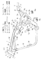
図1は本発明の一実施形態である車体フレームを備えた自動二輪車の側面図である。
自動二輪車は、車体フレーム1の前端のヘッドパイプ部材2に支持されたステアリング軸13(図2)にフロントフォーク3を取り付け、このフロントフォーク3に前車輪4を取り付け、車体フレーム1の中央下部のスイングアームブラケット5にピボット軸6を介して揺動自在に軸支されたスイングアーム7に後車輪8を取り付け、車体フレーム1の前下部に取り付けたエンジン9で、図示しない動力伝達機構を介して後車輪8を駆動するとともに、フロントフォーク3の上端部に固定したハンドル10で操向するように構成されている。
【0011】
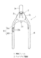
前記車体フレーム1は、外部からできるだけ見えないように、車体フレーム1に支持される燃料タンク23、シート35およびサイドカバー40によって隠蔽する、いわゆるアメリカンタイプのフレームであって、図2(A)に側面図で示すように、前記ヘッドパイプ部材2から後方へ延び、湾曲部15で下方に湾曲してスイングアーム7(図1)のピボット軸6(図1)を支持する左右2つのスイングアームブラケット5に至るメインフレーム14と、ヘッドパイプ部材2から下方へ延び、前記スイングアームブラケット5に至る左右2本のダウンチューブ18と、前記メインフレーム14の湾曲部15から後方へ延びる左右2本のパイプ製シートレール19と、前記スイングアームブラケット5から後方へ延び、連結部材21を介して前記シートレール19に連結される左右2本のパイプ製補強メンバ20とを備える。
【0012】
前記ヘッドパイプ部材2は閉断面形状の横断面を有する溶接可能な中空の鋳造品からなり、フロントフォーク3に連結されたステアリング軸13を支持するヘッドパイプ2aと、前記メインフレーム前部16と突き合わされるメインフレーム連結部2bと、前記ダウンチューブ18の上端を差込み可能な下向きのソケット2cとを有する。
【0013】
前記メインフレーム14は、前記湾曲部15と、この湾曲部15と前記ヘッドパイプ部材2とを連結するメインフレーム前部16と、前記スイングアームブラケット5と前記湾曲部15とを連結するメインフレーム後部17とから構成されている。メインフレーム前部16の上面には燃料タンク23(図1)が装着される。なお、本実施形態では、V型2気筒エンジンの一例を示している。
【0014】
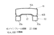
前記メインフレーム前部16は、図2のVII −VII 線断面図である図7に示すように、長手方向に沿った分割面で上下に二分割されたプレス成形品である分割体16A,16Bを溶接して一体化した中空形状のものであり、下側の分割体16Bの下面には長手方向に延びる凹部22が形成されている。このように、構成することにより、従来のパイプ構成の左右1対のメインフレームの間隔に比べて、小さい横幅で、所要の剛性と強度を得ることができ、軽量化も可能となる。また、このように横幅を小さくできるので、メインフレーム前部16の上面を跨いで図8に示すように装着される燃料タンク23の容量を大きくすることができる。
【0015】
また、前記メインフレーム前部16は、図3に平面図で示すように、前端から湾曲部15に向かって横幅が徐々に大きくなる形状とされている。これにより、スイングアームブラケット5周辺に向かうほど高い値が要求されるフレーム剛性を、容易に確保できる。なお、メインフレーム前部16を従来のパイプと同様な引抜き成形で加工する場合、長手方向に同一幅となるので、上記のような平面テーパ状のメインフレーム前部16は得られない。
【0016】
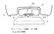
さらに、図8に示したメインフレーム前部16の下面に形成される凹部22のために、エンジン9のヘッド部とメインフレーム前部16との間にメインハーネス33やエンジン補機用のホース34等を配線・配管するためのスペースを容易に確保できる。これに対し、角形パイプ材でメインフレーム前部16を構成する場合には、このような凹部22を形成できないので、エンジン9のヘッド部とメインフレーム前部16との間や、メインフレーム前部16の側部にメインハーネス33やエンジン補機用のホース34等を配線・配管するスペースを確保しなければならないが、この場合には配管・配線のスペースのために燃料タンク23の容量が小さくなる。
【0017】
前記湾曲部15も閉断面形状の横断面を有する溶接可能な中空の鋳造品からなる。ここで、横断面とは、接続される各パイプ部材13,16,18の長手方向と直交する断面をいう。湾曲部15は、図2(B)の縦断面図に示すように、前記メインフレーム前部16の後端のソケット16aに差込まれて、いわゆるインロー嵌合される小径となった上向きの差込部15aと、前記メインフレーム後部17の上端が差込まれる左右2つの下向きのソケット15bと、前記シートレール13の前端が差込まれる左右2つの後ろ向きのソケット15cとを有する。前記メインフレーム前部16と前記湾曲部15とは、湾曲部15の上端の差込部15aをメインフレーム前部16の後端のソケット16aに差し込んでインロー嵌合した後で溶接することにより連結される。また、前記メインフレーム前部16の前端も、前記ヘッドパイプ部材2のメインフレーム連結部2bにインロー嵌合して溶接することにより連結されている。
【0018】
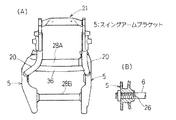
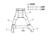
前記スイングアームブラケット5も閉断面形状の横断面を有する溶接可能な中空の鋳造品からなり、スイングアーム7のピボット軸6を図5(B)に示すように支持する軸支孔26と、エンジン9(図1)の後部を支持する上下2つのエンジンマウント27と、図2(C)に縦断面図で示すように、前記メインフレーム後部17の下端のソケット17aにインロー嵌合される上向きの差込部5aと、図2(D)に縦断面図で示すように、前記補強メンバ20の下端のソケット20aにインロー嵌合される後ろ向きの差込部5bとを有する。なお、左側のスイングアームブラケット5は、さらに図2(E)に縦断面図で示すように、左側のダウンチューブ18の後端のソケット18aにインロー嵌合される前向きの差込部5cを有する。図2(A)に示す左右2つのスイングアームブラケット5は、両ブラケットに跨がる上下2本の補強パイプ28A,28B(図5(A))を介して一体に連結されている。
【0019】
前記湾曲部15と前記スイングアームブラケット5とは、メインフレーム後部17の上端を前記湾曲部15のソケット15bに差し込んで溶接するとともに、メインフレーム後部17の下端のソケット17aにスイングアームブラケット5の差込部5aを差し込んで溶接することにより、メインフレーム後部17を介して連結される。
【0020】
このように、湾曲部15が溶接可能な中空の鋳造品で形成されているから、前記メインフレーム14は、湾曲部15にメインフレーム前部16とメインフレーム後部17を溶接することにより構成でき、しかも湾曲部15の溶接部を溶接し易い形状に設計できるので、溶接工数を大幅に低減できる一方で、所要の剛性を確保できる。さらに、鋳造品からなる湾曲部15には、必要に応じて、シートレール19との接続部やその他の補強ガセット類も溶接可能な部材として一体形成できるので、車体フレーム1の構成がより容易になる。
【0021】
また、前記ヘッドパイプ部材2およびスイングアームブラケット5も、閉断面形状の横断面を有し、溶接可能な中空の鋳造品としていて、それらの溶接部を溶接し易い形状に設計できるので、メインフレーム14をヘッドパイプ部材2やスイングアームブラケット5に容易に溶接でき、より一層溶接工数を低減できる。さらに、鋳造品からなるヘッドパイプ部材2やスイングアームブラケット5には、ラジエータの支持部2d(図4)、エンジンマウント27等の他部品取付ブラケットやその他の補強ガセット類も溶接可能な部材として一体形成できるので、車体フレーム1の構成がより一層容易になる。なお、ヘッドパイプ部材2およびスイングアームブラケット5のうち、一方だけを前記鋳造品とした場合でも、従来のパイプ構造の場合よりも、溶接工数を低減できる。
【0022】
前記左右2本のダウンチューブ18のうち、左側のダウンチューブ18は、その上端を前記ヘッドパイプ部材2のソケット2cに差し込み、下端のソケット18aに前記スイングアームブラケット5の差込部5cを差し込んでインロー嵌合し溶接することにより、ヘッドパイプ部材2とスイングアームブラケット5とに連結される。これに対して、右側のダウンチューブ18は、図3および図4に平面図および正面図で示すように、前後2部材18A,18Bからなり、両部材18A,18Bはボルト29Aで締付け固定して連結されている。上部材18Aは、その上端を前記ヘッドパイプ部材2のソケット2cに差し込んで溶接することによりヘッドパイプ部材2に連結される。下部材18Bは、その下端を対応する前記スイングアームブラケット5にボルト29Bで締付け固定されている。これにより、車体フレーム1へエンジン9(図1)を搭載するときに、右側のダウンチューブ18の下部材18Bを、上部材18Aおよびスイングアームブラケット5から外して、その搭載作業を容易に行うことができる。なお、図2および図3のダウンチューブ18に溶接された2eは、エンジン取付用のブラケットである。
【0023】
図7に示すように、メインフレーム前部16の下側分割体16Bの下面には、閉断面形状の横断面を有する溶接可能な中空の鋳造品からなるブラケット30が溶接されており、このブラケット30の左右2つのソケット30aに、図2(A)の左右2つの角形補強パイプ31の一端を差し込んでから溶接し、他端を、前記ヘッドパイプ部材2に突き合わせ溶接することにより、メインフレーム前部16とダウンチューブ18との結合部近傍の補強が図られている。
【0024】
後部の連結部材21は、リヤサスペンション11を支持する支軸12の軸支孔32と、左右2本のシートレール19の後端をインロー嵌合される左右2つの前向きのソケット21aと、補強メンバ20の上端をインロー嵌合される左右2つの下向きのソケット21bとを有する。メインフレーム14の一部材である湾曲部15のソケット15cにシートレール19の前端を差し込んで溶接するともに、シートレール19の後端を前記連結部材21のソケット21aに差し込んで溶接することにより、前記湾曲部15と連結部材21とがシートレール19を介して連結される。左右2本のシートレール19の上には運転者のシート35(図1)が装着される。
【0025】
また、補強メンバ20の上端を前記連結部材21のソケット21bに差し込んで溶接するとともに、補強メンバ20の下端のソケット20aに前記スイングアームブラケット5の差込部5b(図2(D))を差し込んでインロー嵌合してから溶接することにより、スイングアームブラケット5と連結部材21とが、補強メンバ20を介して連結される。左右2本の補強メンバ20は、これら両メンバ間に跨がって溶接される補強パイプ36(図3)によって一体に連結されている。なお、前記湾曲部15は、本発明の一実施形態では、図1に示すように燃料タンク23とシート35の接続部近傍に位置している。
【0026】
【発明の効果】
以上のように、本発明の請求項1に係る自動二輪車の車体フレームによれば、メインフレームの湾曲部が閉断面形状の横断面を有し、溶接可能な中空の鋳造品によって形成されており、前記湾曲部に、前記ヘッドパイプ部材に連結されるメインフレーム前部と、前記スイングアームブラケットに連結されるメインフレーム後部とが溶接されているため、溶接工数を大幅に低減できるとともに、鋳造型が小型で済むので、製造コストが低い。
【0027】
また、本発明の請求項2に係る自動二輪車の車体フレームによれば、メインフレーム前部が、中空形状であり、かつ、長手方向に沿った分割面で分割された複数の分割体を溶接してなるものとしているため、パイプ構成のメインフレームと同じ剛性を得るのに、パイプ構成の場合よりも軽量化が可能となるとともに、メインフレームの幅寸法も小さくできるので、メインフレームを跨いで装着する燃料タンクの容量をそれだけ増大させることができる。また、メインフレーム前部をプレス成形する場合でも、メインフレーム全体をプレス成形するのに比べて、成形型が小型で済むので、製造コストが低い。
【図面の簡単な説明】
【図1】本発明の一実施形態に係る車体フレームを備えた自動二輪車を示す側面図である。
【図2】(A)は同車体フレームの側面図、(B)〜(E)は(A)におけるB〜E部の縦断面図である。
【図3】同車体フレームの平面図である。
【図4】同車体フレームの正面図である。
【図5】(A)は同車体フレームの背面図、(B)はピボット軸の支持部を示す断面図である。
【図6】図2(A)におけるA方向矢視図である。
【図7】図2におけるVII −VII 線断面図である。
【図8】車体フレームへのハーネス,ホース類取付け状態を示す要部の横断面図である。
【符号の説明】
1…車体フレーム、2…ヘッドパイプ部材、5…スイングアームブラケット、6…ピボット軸、13…ステアリング軸、14…メインフレーム、15…湾曲部、16…メインフレーム前部、16A,16B…分割体、17…メインフレーム後部、22…凹部[0001]
BACKGROUND OF THE INVENTION
The present invention relates to a vehicle body frame that is covered with a fuel tank of a motorcycle so as not to be visible from the outside, that is, a vehicle body frame of a so-called American type motorcycle.
[0002]
[Prior art]
The body frame of this type of large motorcycle has a pipe structure in which a plurality of pipe members are complexly connected as main materials in order to obtain rigidity and strength, and is equivalent to a portion around the head pipe and below the rear portion of the fuel tank of the main frame. Reinforcing gussets and brackets are frequently used for the main parts that require further rigidity and strength, such as around curved parts and swing arm brackets.
[0003]
[Problems to be solved by the invention]
However, in the case of the body frame having the pipe structure, there are many troublesome places for welding and long places for welding, which increases the number of manufacturing steps. In addition, in order to ensure the required torsional rigidity, the distance between the left and right of the pair of main pipes must be increased, so that the capacity of the fuel tank mounted over the main pipes is reduced accordingly.
On the other hand, there is a vehicle body frame having a monocoque main frame (see Utility Model Registration No. 2512877). According to this, welding of a reinforcing gusset or the like is not required, but a large mold is required, and the manufacturing cost is reduced. In the American type motorcycle that covers the main frame with a fuel tank, the fuel tank capacity decreases.
[0004]
The present invention has been made in view of the above circumstances, and a first object of the present invention is to provide a body frame of a motorcycle that has a required rigidity and is easy to manufacture and inexpensive, and has a capacity of a fuel tank. A second object of the present invention is to provide a motorcycle body frame capable of increasing the size of the motorcycle.
[0005]
[Means for Solving the Problems]
In order to achieve the above object, the body frame of the motorcycle according to
According to this configuration , the same rigidity as the main frame of the pipe configuration can be obtained, but the weight can be reduced as compared with the case of the pipe configuration, and the horizontal width of the main frame can be reduced, so that the main frame is mounted across the main frame. The capacity of the fuel tank can be increased accordingly. Further, even when the front part of the main frame is press-molded, the manufacturing cost is low because the molding die can be made smaller than when the whole main frame is press-molded. Furthermore, it is possible to secure a space for passing a harness or a hose between the front portion of the main frame and the engine without reducing the capacity of the fuel tank mounted over the main frame.
[0006]
The body frame of a motorcycle according to a second aspect of the present invention is the structure of the first aspect, wherein the front portion of the main frame has a shape in which the lateral width gradually increases from the front end toward the curved portion. According to this configuration, it is possible to easily ensure the frame rigidity that requires a higher value toward the periphery of the swing arm bracket.
[0007]
The body frame of the motorcycle according to
According to this configuration , the main frame leading from the head pipe member to the swing arm bracket can be configured by welding the main frame front portion and the main frame rear portion to the curved portion made of a weldable hollow casting. The number of welding processes can be greatly reduced. Further, since the curved portion to be cast is a part of the main frame, the casting mold can be made small, so that the manufacturing cost is low.
[0008]
A motorcycle body frame according to claim 4 is the structure of
[0009]
A motorcycle body frame according to a fifth aspect of the present invention is the vehicle body frame according to any one of the first to fourth aspects, further comprising two left and right down tubes extending downward from the head pipe member to the swing arm bracket. The down tube includes an upper member and a lower member which are divided in the front and rear directions, and the lower member is detachably connected between the upper member and the swing arm bracket by a fastening member.
According to this configuration, when the engine is mounted on the vehicle body frame, the rear member of the right down tube can be removed from the front member and the swing arm bracket, and the mounting operation can be easily performed.
[0010]
DETAILED DESCRIPTION OF THE INVENTION
Hereinafter, preferred embodiments of the present invention will be described in detail with reference to the drawings.
FIG. 1 is a side view of a motorcycle having a body frame according to an embodiment of the present invention.
In the motorcycle, a
[0011]
The
[0012]
The
[0013]
The
[0014]
As shown in FIG. 7 which is a cross-sectional view taken along the line VII-VII in FIG. 2, the main
[0015]
Further, as shown in a plan view in FIG. 3, the main
[0016]
Further, because of the
[0017]
The
[0018]
The
[0019]
The bending
[0020]
Thus, since the
[0021]
Also, the
[0022]
Of the two left and right down
[0023]
As shown in FIG. 7, a
[0024]
The
[0025]
Further, the upper end of the reinforcing
[0026]
【The invention's effect】
As described above, according to the vehicle body frame of the motorcycle according to
[0027]
According to the body frame of the motorcycle according to
[Brief description of the drawings]
FIG. 1 is a side view showing a motorcycle including a body frame according to an embodiment of the present invention.
2A is a side view of the vehicle body frame, and FIGS. 2B to 2E are longitudinal sectional views of portions B to E in FIG. 2A.
FIG. 3 is a plan view of the vehicle body frame.
FIG. 4 is a front view of the vehicle body frame.
5A is a rear view of the vehicle body frame, and FIG. 5B is a cross-sectional view showing a support portion of the pivot shaft.
6 is a view in the direction of arrow A in FIG.
7 is a cross-sectional view taken along line VII-VII in FIG.
FIG. 8 is a cross-sectional view of a main part showing a state in which a harness and hoses are attached to a vehicle body frame.
[Explanation of symbols]
DESCRIPTION OF
Claims (5)
前記ヘッドパイプ部材から前記湾曲部に至るメインフレーム前部が、長手方向に沿った分割面で上下二分割された複数の分割体を溶接してなるものであり、
下側の分割体の下面に長手方向に延びる凹部が形成されている自動二輪車の車体フレーム。A main frame that extends rearward from the head pipe member that supports the steering shaft, curves downward at the curved portion, and reaches the swing arm bracket that supports the pivot shaft of the swing arm,
The main frame front leading to the curved portion from the head pipe member is made of by welding a plurality of divided bodies that are vertically divided into two parts with dividing plane along the long side direction,
A motorcycle body frame in which a recess extending in a longitudinal direction is formed on a lower surface of a lower divided body .
前記湾曲部に、前記ヘッドパイプ部材に連結されるメインフレーム前部と、前記スイングアームブラケットに連結されるメインフレーム後部とが溶接されている自動二輪車の車体フレーム。 The body frame of the motorcycle according to claim 1 or 2 , wherein the curved portion is formed by a weldable hollow cast product having a cross section having a closed cross section.
A body frame of a motorcycle, wherein a main frame front portion connected to the head pipe member and a main frame rear portion connected to the swing arm bracket are welded to the curved portion.
右側のダウンチューブは、前後に分割された上部材および下部材からなり、前記下部材が、前記上部材と前記スイングアームブラケットとの間に、締結部材により取り外し可能に連結されている自動二輪車の車体フレーム。 The motorcycle body frame according to any one of claims 1 to 4 , further comprising two left and right down tubes extending downward from the head pipe member and reaching the swing arm bracket.
The right down tube is composed of an upper member and a lower member which are divided into front and rear parts, and the lower member is detachably connected by a fastening member between the upper member and the swing arm bracket. Body frame.
Priority Applications (1)
| Application Number | Priority Date | Filing Date | Title |
|---|---|---|---|
| JP15487399A JP4249331B2 (en) | 1999-06-02 | 1999-06-02 | Motorcycle body frame |
Applications Claiming Priority (1)
| Application Number | Priority Date | Filing Date | Title |
|---|---|---|---|
| JP15487399A JP4249331B2 (en) | 1999-06-02 | 1999-06-02 | Motorcycle body frame |
Publications (2)
| Publication Number | Publication Date |
|---|---|
| JP2000344169A JP2000344169A (en) | 2000-12-12 |
| JP4249331B2 true JP4249331B2 (en) | 2009-04-02 |
Family
ID=15593807
Family Applications (1)
| Application Number | Title | Priority Date | Filing Date |
|---|---|---|---|
| JP15487399A Expired - Fee Related JP4249331B2 (en) | 1999-06-02 | 1999-06-02 | Motorcycle body frame |
Country Status (1)
| Country | Link |
|---|---|
| JP (1) | JP4249331B2 (en) |
Cited By (1)
| Publication number | Priority date | Publication date | Assignee | Title |
|---|---|---|---|---|
| EP2502816A1 (en) | 2011-03-25 | 2012-09-26 | Honda Motor Co., Ltd. | Frame structure of saddle-ride type vehicle |
Families Citing this family (6)
| Publication number | Priority date | Publication date | Assignee | Title |
|---|---|---|---|---|
| JP4847233B2 (en) * | 2006-06-30 | 2011-12-28 | 本田技研工業株式会社 | Motorcycle frame structure |
| JP6220702B2 (en) | 2014-03-03 | 2017-10-25 | 本田技研工業株式会社 | Body frame structure of saddle riding type vehicle |
| JP6190304B2 (en) * | 2014-03-28 | 2017-08-30 | 本田技研工業株式会社 | Body frame of saddle riding type vehicle |
| JP2016068917A (en) * | 2014-10-02 | 2016-05-09 | 川崎重工業株式会社 | Motorcycle |
| CN111994194B (en) * | 2020-08-30 | 2022-05-17 | 重庆隆鑫机车有限公司 | Universal frame for motorcycle |
| JP7595749B2 (en) | 2021-03-30 | 2024-12-06 | 本田技研工業株式会社 | Saddle-type vehicle |
-
1999
- 1999-06-02 JP JP15487399A patent/JP4249331B2/en not_active Expired - Fee Related
Cited By (1)
| Publication number | Priority date | Publication date | Assignee | Title |
|---|---|---|---|---|
| EP2502816A1 (en) | 2011-03-25 | 2012-09-26 | Honda Motor Co., Ltd. | Frame structure of saddle-ride type vehicle |
Also Published As
| Publication number | Publication date |
|---|---|
| JP2000344169A (en) | 2000-12-12 |
Similar Documents
| Publication | Publication Date | Title |
|---|---|---|
| US6702058B2 (en) | Vehicle body frame structure and manufacturing method of same | |
| JP3869122B2 (en) | Body frame structure of 4-wheel buggy car | |
| JP4516497B2 (en) | Motorcycle body frame | |
| US6371236B1 (en) | Vehicle frame structure of motorcycle | |
| US8104565B2 (en) | Body frame and vehicle | |
| US7383909B2 (en) | Vehicle body frame of motorcycle | |
| CN102233922B (en) | Frame for motor-driven two wheel motorcycle | |
| JP3689273B2 (en) | Structure of suspension device mounting part of the car body | |
| JP4249331B2 (en) | Motorcycle body frame | |
| JPH1179037A (en) | Frame structure of saddle type vehicle | |
| US7883101B2 (en) | Body frame of motorcycle | |
| US7311171B2 (en) | Vehicular suspension installation structure | |
| JP3713703B2 (en) | Car subframe | |
| CN109689488B (en) | Body frame of motorcycle | |
| US10723401B2 (en) | Vehicle body structure of saddle type vehicle | |
| JP5261298B2 (en) | Cover mounting structure for motorcycles | |
| JPH11129966A (en) | Body frame for motorcycles | |
| JPS60176876A (en) | Frame for motorcycle | |
| JP3214783B2 (en) | Fuel tank support structure | |
| JP3643322B2 (en) | Suspension structure of unit swing type engine in motorcycle | |
| JP3701361B2 (en) | Stay structure for mounting accessory parts of motorcycles | |
| JPS6136072A (en) | Car body frame of motorcycle | |
| JP3919626B2 (en) | Spring bracket | |
| CN220640134U (en) | Frame of saddle-type vehicle | |
| JPH06171570A (en) | Frame structure of motorcycle |
Legal Events
| Date | Code | Title | Description |
|---|---|---|---|
| A621 | Written request for application examination |
Effective date: 20051220 Free format text: JAPANESE INTERMEDIATE CODE: A621 |
|
| A131 | Notification of reasons for refusal |
Free format text: JAPANESE INTERMEDIATE CODE: A131 Effective date: 20080325 |
|
| A977 | Report on retrieval |
Effective date: 20080327 Free format text: JAPANESE INTERMEDIATE CODE: A971007 |
|
| A521 | Written amendment |
Free format text: JAPANESE INTERMEDIATE CODE: A523 Effective date: 20080521 |
|
| A131 | Notification of reasons for refusal |
Effective date: 20080701 Free format text: JAPANESE INTERMEDIATE CODE: A131 |
|
| A521 | Written amendment |
Free format text: JAPANESE INTERMEDIATE CODE: A523 Effective date: 20080901 |
|
| TRDD | Decision of grant or rejection written | ||
| A01 | Written decision to grant a patent or to grant a registration (utility model) |
Free format text: JAPANESE INTERMEDIATE CODE: A01 Effective date: 20090113 |
|
| A01 | Written decision to grant a patent or to grant a registration (utility model) |
Free format text: JAPANESE INTERMEDIATE CODE: A01 |
|
| A61 | First payment of annual fees (during grant procedure) |
Effective date: 20090115 Free format text: JAPANESE INTERMEDIATE CODE: A61 |
|
| FPAY | Renewal fee payment (prs date is renewal date of database) |
Free format text: PAYMENT UNTIL: 20120123 Year of fee payment: 3 |
|
| R150 | Certificate of patent (=grant) or registration of utility model |
Free format text: JAPANESE INTERMEDIATE CODE: R150 |
|
| LAPS | Cancellation because of no payment of annual fees |