EP2468419B1 - Bi-directional pneumatic dispenser - Google Patents
Bi-directional pneumatic dispenser Download PDFInfo
- Publication number
- EP2468419B1 EP2468419B1 EP20100196812 EP10196812A EP2468419B1 EP 2468419 B1 EP2468419 B1 EP 2468419B1 EP 20100196812 EP20100196812 EP 20100196812 EP 10196812 A EP10196812 A EP 10196812A EP 2468419 B1 EP2468419 B1 EP 2468419B1
- Authority
- EP
- European Patent Office
- Prior art keywords
- dispenser
- pressure
- port
- valve
- ports
- Prior art date
- Legal status (The legal status is an assumption and is not a legal conclusion. Google has not performed a legal analysis and makes no representation as to the accuracy of the status listed.)
- Active
Links
- 238000004891 communication Methods 0.000 claims description 65
- 239000012530 fluid Substances 0.000 claims description 27
- 239000011345 viscous material Substances 0.000 claims description 9
- 230000003584 silencer Effects 0.000 claims description 4
- 238000003825 pressing Methods 0.000 claims 1
- 230000000994 depressogenic effect Effects 0.000 description 14
- 239000000463 material Substances 0.000 description 9
- 238000007789 sealing Methods 0.000 description 4
- 230000001276 controlling effect Effects 0.000 description 3
- 239000004033 plastic Substances 0.000 description 3
- 238000000926 separation method Methods 0.000 description 3
- 238000010276 construction Methods 0.000 description 2
- 230000001105 regulatory effect Effects 0.000 description 2
- 238000013022 venting Methods 0.000 description 2
- 239000004677 Nylon Substances 0.000 description 1
- 229910000831 Steel Inorganic materials 0.000 description 1
- DHKHKXVYLBGOIT-UHFFFAOYSA-N acetaldehyde Diethyl Acetal Natural products CCOC(C)OCC DHKHKXVYLBGOIT-UHFFFAOYSA-N 0.000 description 1
- 125000002777 acetyl group Chemical class [H]C([H])([H])C(*)=O 0.000 description 1
- 239000004411 aluminium Substances 0.000 description 1
- 229910052782 aluminium Inorganic materials 0.000 description 1
- XAGFODPZIPBFFR-UHFFFAOYSA-N aluminium Chemical compound [Al] XAGFODPZIPBFFR-UHFFFAOYSA-N 0.000 description 1
- 230000006835 compression Effects 0.000 description 1
- 238000007906 compression Methods 0.000 description 1
- 230000001934 delay Effects 0.000 description 1
- 230000009977 dual effect Effects 0.000 description 1
- 239000000945 filler Substances 0.000 description 1
- 239000011888 foil Substances 0.000 description 1
- 239000011521 glass Substances 0.000 description 1
- 229910052751 metal Inorganic materials 0.000 description 1
- 239000002184 metal Substances 0.000 description 1
- 238000012986 modification Methods 0.000 description 1
- 230000004048 modification Effects 0.000 description 1
- 229920001778 nylon Polymers 0.000 description 1
- 239000010959 steel Substances 0.000 description 1
- 230000000007 visual effect Effects 0.000 description 1
Images


Classifications
-
- B—PERFORMING OPERATIONS; TRANSPORTING
- B05—SPRAYING OR ATOMISING IN GENERAL; APPLYING FLUENT MATERIALS TO SURFACES, IN GENERAL
- B05C—APPARATUS FOR APPLYING FLUENT MATERIALS TO SURFACES, IN GENERAL
- B05C17/00—Hand tools or apparatus using hand held tools, for applying liquids or other fluent materials to, for spreading applied liquids or other fluent materials on, or for partially removing applied liquids or other fluent materials from, surfaces
- B05C17/005—Hand tools or apparatus using hand held tools, for applying liquids or other fluent materials to, for spreading applied liquids or other fluent materials on, or for partially removing applied liquids or other fluent materials from, surfaces for discharging material from a reservoir or container located in or on the hand tool through an outlet orifice by pressure without using surface contacting members like pads or brushes
- B05C17/015—Hand tools or apparatus using hand held tools, for applying liquids or other fluent materials to, for spreading applied liquids or other fluent materials on, or for partially removing applied liquids or other fluent materials from, surfaces for discharging material from a reservoir or container located in or on the hand tool through an outlet orifice by pressure without using surface contacting members like pads or brushes with pneumatically or hydraulically actuated piston or the like
-
- B—PERFORMING OPERATIONS; TRANSPORTING
- B05—SPRAYING OR ATOMISING IN GENERAL; APPLYING FLUENT MATERIALS TO SURFACES, IN GENERAL
- B05C—APPARATUS FOR APPLYING FLUENT MATERIALS TO SURFACES, IN GENERAL
- B05C17/00—Hand tools or apparatus using hand held tools, for applying liquids or other fluent materials to, for spreading applied liquids or other fluent materials on, or for partially removing applied liquids or other fluent materials from, surfaces
- B05C17/005—Hand tools or apparatus using hand held tools, for applying liquids or other fluent materials to, for spreading applied liquids or other fluent materials on, or for partially removing applied liquids or other fluent materials from, surfaces for discharging material from a reservoir or container located in or on the hand tool through an outlet orifice by pressure without using surface contacting members like pads or brushes
- B05C17/01—Hand tools or apparatus using hand held tools, for applying liquids or other fluent materials to, for spreading applied liquids or other fluent materials on, or for partially removing applied liquids or other fluent materials from, surfaces for discharging material from a reservoir or container located in or on the hand tool through an outlet orifice by pressure without using surface contacting members like pads or brushes with manually mechanically or electrically actuated piston or the like
- B05C17/014—Hand tools or apparatus using hand held tools, for applying liquids or other fluent materials to, for spreading applied liquids or other fluent materials on, or for partially removing applied liquids or other fluent materials from, surfaces for discharging material from a reservoir or container located in or on the hand tool through an outlet orifice by pressure without using surface contacting members like pads or brushes with manually mechanically or electrically actuated piston or the like comprising means for preventing oozing
-
- Y—GENERAL TAGGING OF NEW TECHNOLOGICAL DEVELOPMENTS; GENERAL TAGGING OF CROSS-SECTIONAL TECHNOLOGIES SPANNING OVER SEVERAL SECTIONS OF THE IPC; TECHNICAL SUBJECTS COVERED BY FORMER USPC CROSS-REFERENCE ART COLLECTIONS [XRACs] AND DIGESTS
- Y10—TECHNICAL SUBJECTS COVERED BY FORMER USPC
- Y10T—TECHNICAL SUBJECTS COVERED BY FORMER US CLASSIFICATION
- Y10T137/00—Fluid handling
- Y10T137/8593—Systems
- Y10T137/86493—Multi-way valve unit
- Y10T137/86574—Supply and exhaust
- Y10T137/8667—Reciprocating valve
- Y10T137/86694—Piston valve
- Y10T137/8671—With annular passage [e.g., spool]
-
- Y—GENERAL TAGGING OF NEW TECHNOLOGICAL DEVELOPMENTS; GENERAL TAGGING OF CROSS-SECTIONAL TECHNOLOGIES SPANNING OVER SEVERAL SECTIONS OF THE IPC; TECHNICAL SUBJECTS COVERED BY FORMER USPC CROSS-REFERENCE ART COLLECTIONS [XRACs] AND DIGESTS
- Y10—TECHNICAL SUBJECTS COVERED BY FORMER USPC
- Y10T—TECHNICAL SUBJECTS COVERED BY FORMER US CLASSIFICATION
- Y10T137/00—Fluid handling
- Y10T137/8593—Systems
- Y10T137/87169—Supply and exhaust
Definitions
- the present invention relates to a pneumatic dispenser and a valve arrangement for such a dispenser.
- the dispenser is for applying a force to a container holding viscous material to cause the viscous material to be dispensed from the container.
- European Patent Application EP0551998 A1 discloses a dispenser for viscous material.
- the dispenser comprises an actuating cylinder containing a piston connected to a rod which extends forward out of the cylinder, and a pistol grip body, in which is mounted a trigger operably connected with a pressure regulator.
- Actuation of the trigger causes a pressure to be applied to the cylinder via a flexible pipe extending from a regulated two port valve inside the pistol grip to the rear end of the cylinder.
- the applied pressure causes the piston and, hence, the rod to move forward.
- a keep is located forward of the cylinder. The keep enables a removable cartridge to be inserted such that application of a force by the rod to a piston inside the cartridge causes viscous material to be dispensed from the cartridge through an aperture.
- a switch located at an end of the pistol grip distal to the cylinder is used to select between different outlets leading to opposite sides of the piston to enable the piston to be pneumatically driven in either the forward or the rearward direction, according to the selection of the switch.
- the pressure is vented from the cylinder after the trigger is released by a dump valve at the rear of the cylinder.
- the dump valve closes until the applied pressure drops when the trigger is released and the dump valve opens to act as a rapid exhaust.
- Dispensers of a similar general construction as disclosed in EP0551998 A1 which also have a flexible pipe extending from the pistol grip to the rear of the cylinder but have a button at the rear of the cylinder that allows the operator to control whether the pressure applied through the flexible pipe from the pistol grip is applied directly to the rear portion of the cylinder on one side of the piston, or through a coiled tube and the piston to the front portion of the cylinder on the other side of the piston.
- a pressure activated dump valve is used to vent the cylinder to atmosphere when the trigger is released.
- a common feature of these dispensers is that, in order to change the direction of movement of the piston, the operator must either use two hands or at least move the hand holding the pistol grip from its normal position with the index finger of this hand on the trigger. This causes delays in the operation of the dispenser while the operator moves his hand(s) in order to make the necessary adjustments to the dispenser.
- Another common feature of these dispensers is that a flexible pipe extends from the pistol grip to the rear end of the cylinder. This flexible pipe hangs loosely from the cylinder and can be a safety hazard. It is also prone to damage and can detract from the visual appearance of the dispenser. The operation of the dump valve to vent the cylinder can involve high levels of noise.
- US2,692,706 discloses an air pressure caulking gun with a pivotally mounted trigger member with a finger loop for advancing and retreating the rod according to the preamble of claim 1.
- a dispenser comprising a handle; a cylinder secured with respect to the handle; a piston moveable inside the cylinder, the piston dividing the cylinder into a front chamber and a rear chamber; and a rod arranged to move with the piston, the rod extending from the piston through an aperture in a front end of the cylinder.
- the handle comprises an actuation arrangement comprising first and second triggers, each for actuation by an operator holding the handle to selectively apply pressure to a respective one of the front and rear chambers, thereby controlling advance and retreat of the rod.
- the first and second triggers are positioned on the handle for actuation by respective fingers of a hand of the operator holding the handle and are depressable towards the handle.
- the actuation arrangement allows an operator holding the handle to selectively apply pressure inside the cylinder on a respective side of the piston to control advance and retreat of the rod relative to the cylinder.
- This allows the operator to fully operate the gun using only one hand and without having to move that hand from its normal position on the handle. The operator can therefore quickly switch between advancing the rod and retreating the rod through the aperture in the cylinder, allowing the dispenser to be used more efficiently.
- the actuation arrangement comprises a valve arrangement having operating ports each connected to the cylinder on a respective side of the piston, one or more inlet ports for supplying pressurised fluid from a pressure source to the cylinder through the operating ports and one or more exhaust ports for releasing pressure inside the cylinder through the operating ports.
- the one or more exhaust ports are connected to one or more silencers.
- the silencers further reduce the volume of sound emitted from the dispenser due to fluid flowing through the one or more exhaust ports.
- the one or more exhaust ports are connected to a single silencer. The use of a single silencer facilitates making the dispenser compact.
- the valve arrangement comprises a single valve, facilitating fitting the valve arrangement into the handle.
- the valve comprises a body and first and second members moveable within the body to actuate the valve, the first and second members being selectively moveable upon actuation of the actuation arrangement.
- the moveable members allow a simple and reliable mechanical link to be made between the members and the actuation arrangement.
- the dispenser is arranged such that when both triggers are depressed by the operator at the same time, a substantial increase in pressure on both sides of the piston within the cylinder is prevented, such as by venting the inlet ports to the exhaust ports (which could still result in a small pressure increase on both sides of the piston due to the finite resistance of the exhaust flow pressure). By preventing substantial pressure build-up on both sides of the piston, damage to the dispenser caused by excessive pressure within the dispenser is prevented.
- the dispenser is arranged such that different pressures can be applied to different inlet ports.
- a lower pressure can be applied to the side of the piston that causes the rod to retreat than the pressure applied to the side of the piston that causes the rod to advance.
- the pressure applied to advance the rod causes the rod to apply a force to a cartridge in the cartridge holder to dispense material from the cartridge.
- This requires a larger pressure to be achieved than the pressure required merely to cause the rod to retreat, as there is substantially no or little resistance to the rod being retreated.
- the lower pressure applied to retreat the rod ensures that the rod does not retreat too rapidly.
- the dispenser is therefore quieter when the rod is retreating and more economical, since a lower pressure needs to be maintained for retreating the rod, which requires less air.
- the valve comprises a body and first and second moveable members, the body defining a chamber and first, second, third, fourth and fifth ports into the chamber, the first and second members being moveable within the chamber to selectively open and close fluidic communication paths between the ports, the first member being movable between two positions to selectively enable fluidic communication between the second port and either the first port or the third port, the second member being movable between two positions to selectively enable fluidic communication between the fourth port and either the third port or the fifth port.
- the first and second members may be constrained to move along the same axis and may be biased away from each other into respective rest positions, for example by a resilient biasing member disposed between them.
- the members may be arranged to be capable of contacting each other inside the chamber to limit how much both members can be inserted at the same time.
- the first, third and fifth ports are in fluidic communication in configurations of the first and second members with both the first and second members positioned away from their respective rest positions.
- fluidic communication when the first and second members are in their respective rest positions, fluidic communication is enabled between the second port and the third port, and between the third port and the fourth port, and fluidic communication is prevented between the first port and the second port, and between the fourth port and the fifth port; when the first member is positioned as closely as possible to the second member while the second member remains in its rest position, fluidic communication is enabled between the second port and the third port, and between the fourth port and the fifth port, and fluidic communication is prevented between the first port and the second port, and between the third port and the fourth port; when the second member is positioned as closely as possible to the first member while the first member remains in its rest position, fluidic communication is enabled between the first port and the second port, and between the third port and the fourth port, and fluidic communication is prevented between the second port and the third port, and between the fourth port and the fifth port; and wherein there is no configuration of the first and second members in which fluidic communication is enabled between the first port and the second port, and between the fourth port and the fifth port, without
- a compact five-port valve can be constructed in accordance with the above embodiments.
- space savings are achieved by allowing the operating ports to share a common exhaust or inlet port and/or a fail-safe provided by preventing substantial pressure build-up at both operating ports.
- the second and fourth ports are connected as operating ports, one of the first, third and fifth ports being connected as a supply or exhaust port and the other two being connected as the exhaust or supply ports, respectively.
- a second aspect of the invention provides a dispenser comprising a stock portion defining a handle; a cylinder secured to the stock portion; a piston moveable inside the cylinder, the piston dividing the cylinder into a front space and a rear space; a rod arranged to move with the piston, the rod extending from the piston through the front space; and a first fluid conduit for enabling a pressure to be applied from the stock portion to the rear space to advance the rod, the first fluid conduit passing through the front space.
- the stock portion and the cylinder may together fully enclose the first fluid conduit.
- the valve arrangement and the cylinder can therefore be arranged to be in fluidic communication entirely through fluid paths contained within the dispenser, i.e. through the handle and passing directly into the cylinder without first leaving the handle. This ensures that the dispenser is compact, and provides a simpler form factor of the dispenser due to the absence of any visible external fluid paths.
- the dispenser is also safer as all fluid paths are contained within the dispenser and not exposed, and therefore are less liable to be damaged.
- the dispenser further comprises a second fluid conduit passing from the stock portion to the front space for enabling a pressure to be applied to the front space to retreat the rod, the second fluid conduit passing directly from the stock portion to the front space.
- the stock portion and the cylinder fully enclose the first and second fluid conduits.
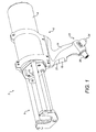
- a pneumatic dispenser 2 comprises a cylinder 4 secured to a stock portion 6 and a cartridge holder 8 secured forward of the cylinder 4.
- the cylinder has a wall with a substantially annular cross-section.
- the cartridge holder 8 is arranged to receive a cartridge (not shown) containing viscous material and is arranged such that the cartridge held in the cartridge holder 8 is disposed in a dispensing relationship relative to the cylinder 4, as described below.
- the specific embodiment depicted in Figure 1 is arranged to dispense material from two component cartridges having two barrels, one for each componet material and has two plungers, one for each barrel.
- a plurality of rods 10 extend through a front end of the cylinder 4 through respective apertures which seal around the rods 10.
- the rods 10 extend substantially parallel to a longitudinal axis of the cylinder 4.
- a plunger 12 for engaging a piston inside the cartridge is coupled to two of the rods 10 at a forward end of the rods 10.
- a further, smaller plunger is coupled to the remaining rod. The smaller plunger and remaining rod are obscured behind the cartrdige holder 4 in Figure 1 .
- the rods 10 and the plungers 12 are moveable relative to the cylinder 4 along a longitudinal axis of the rods 10 such that a force can be applied to the cartridge by the plungers 12 when the cylinder 4 is pressurised to cause viscous material to be dispensed from the cartridge.
- the stock portion 6 comprises a handle 14 extending away from the cylinder 4 in the vicinity of the front end of the cylinder 4.
- the handle 14 is ergonomically shaped to be held by one hand of a human operator of the dispenser 2 and comprises a drive trigger 18 and a return trigger 20 for, respectively, controlling the advance and return (i.e. retreat) of the rods 10.
- the drive trigger 18 and the return trigger 20 face substantially forward and are positioned on the handle 14 such that each trigger can be individually depressed by the operator while the operator's hand is holding the handle 14.
- the drive trigger 18 is positioned on the handle 14 further from the cylinder 4 such that it is actuable by the middle finger of the operator's hand, and the return trigger 20 is positioned on the handle 14 closer to the cylinder 4 such that it is actuable by the index finger of the operator's hand.
- the handle 14 also comprises a regulator 22 at an end of the handle 14 distal to the cylinder 4.
- the regulator 22 has a quick release pressure connector 24 arranged to connect to a pressure hose to receive pressurised fluid (for example, compressed air) from a pressure source (not shown) and a dial 26 for controlling the pressure of the pressurised fluid supplied by the regulator 22.
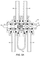
- a piston 28 coupled to the rods 10 for driving the rods 10 is slidingly accommodated within the cylinder 4.
- the piston 28 divides the inside of the cylinder 4 into two chambers: a drive chamber 30 on the rearward side of the piston 28 between the piston 28 and a closure member 32 closing the back end of the cylinder 4, and a return chamber 34 on the forward side of the piston 28 between the piston 28 and the apertures around the rods 10.
- the rods 10 are coupled to the piston 28 and extend forward of the piston 28. The rods 10 thus move with the piston 28 relative to the cylinder 4 parallel to the longitudinal axis of the cylinder 4.
- a valve 36 is situated within the handle 14 so that it is actuable by the return trigger 20 and the drive trigger 18.
- the return trigger 20 is arranged to directly engage a first spool (described below) of the valve and the drive trigger 18 is arranged to actuate a second spool (described below) of the valve via a yoke while the drive trigger 20 pivots about a pivot forward of the valve.
- a return conduit 38 passes from the valve 36 through an aperture in the cylinder 4 into the return chamber 34 to enable fluidic communication between the valve 36 and the return chamber 34.
- a drive conduit 40 passing from the valve 36 to the drive chamber 30 comprises a first drive conduit portion 42, which passes from the valve 36 to the return chamber 34 through a further aperture in the cylinder 4. Fluid is prevented from escaping the return chamber 34 between the respective apertures and the outside of the first drive conduit portion 42 or the return conduit 38 by a sealing member 44.
- the sealing member 44 sealingly holds O-rings in place around each of the return conduit 38 and the drive conduit 40 and against an inner surface of the cylinder 4 around each of the apertures.
- a second drive conduit portion 46 passes from the sealing member through the return chamber 34 and extends through an aperture in the piston 28 into the drive chamber 30 to enable fluidic communication between the valve 36 and the drive chamber 30.
- the aperture in the piston 28 seals around the second drive conduit portion 46, and the drive conduit 40 is therefore sealed from the return chamber 34. In operation, the piston 28 slides over the second drive conduit portion 46 whilst maintaining the seal around it.
- the valve 36 is in fluidic communication with a pressure inlet conduit 48 connected to the regulator 22.
- the valve 36 is also in fluidic communication with an exhaust 50 for releasing pressure in the cylinder 4 to the atmosphere.
- the exhaust 50 is arranged to act as a silencer in order to reduce the noise emitted from the dispenser 2 when the cylinder 4 is vented through the exhaust 50.
- the valve 36 is arranged such that the pressure inlet conduit 48 and the exhaust 50 are each selectively in fluidic communication with the drive chamber 30 and the return chamber 34 under control of the triggers. Actuation of the valve 36 using the triggers enables the operator of the dispenser 2 to selectively enable or prevent fluidic communication between combinations of the pressure inlet conduit 48, the exhaust 50, the drive chamber 30 and the return chamber 34 to advance or retreat the rods 10.
- the dispenser 2 In use, when neither the drive trigger 18 nor the return trigger 20 has been depressed by the operator, the dispenser 2 is in a rest configuration. In the rest configuration, the regulator 22 is disconnected from both the drive chamber 30 and the return chamber 34 and both chambers are connected to the exhaust 50, placing the drive chamber 30 and the return chamber 34 at atmospheric pressure.
- the dispenser 2 When the drive trigger 18 has been fully depressed by the operator, and the return trigger 20 is not depressed, the dispenser 2 is in a drive configuration.
- the regulator 22 In the drive configuration, the regulator 22 is connected the drive chamber 30 and remains disconnected from the return chamber 34, which remains connected to the exhaust 50.
- the exhaust 50 is disconnected from the drive chamber 30, so that pressure builds up in the drive chamber 30, driving the piston 28 and, hence, the rods 10 forward.
- the dispenser 2 When the return trigger 20 has been fully depressed by the operator, and the drive trigger 18 is not depressed, the dispenser 2 is in a return configuration.
- the return configuration fluidic communication between the pressure inlet conduit 48 and the return chamber 34 is enabled, and fluidic communication between the pressure inlet conduit 48 and each of the drive chamber 30 and the exhaust 50 is prevented. Fluidic communication between the exhaust 50 and the drive chamber 30 is enabled, and fluidic communication between the exhaust 50 and the return chamber 34 is prevented.
- pressurised fluid is applied to the return chamber 34, which causes the piston 28 to move rearwards.
- the dispenser 2 When each of the drive trigger 18 and the return trigger 20 are depressed by the same amount, and each are depressed as much as they can both be depressed at the same time, the dispenser 2 is in a free flow configuration. In the free flow configuration, a pressure increase in the drive chamber 30 and/or the return chamber 34 is prevented. This is achieved by enabling fluidic communication between the drive chamber 30 and the exhaust 50 and between the return chamber 34 and the exhaust 50. Fluidic communication is also enabled between the pressure inlet conduit 48 and the exhaust 50.
- both triggers When both triggers are depressed as far as possible, they are effectively coupled to each other via the spools of the valve 36, as described below, so that any inward movement of one trigger carries outward movement of the other trigger.
- an operator can vary between the configurations described above by varying the force applied to each trigger.
- the valve 36 and its link to the triggers are arranged such that, for any amount of depression of either or both the triggers, it is never the case that the regulator 22 is able to supply a substantial increase in pressure to both the drive chamber 30 and the return chamber 34 at the same time.
- the regulator 22 is able to supply a substantial increase in pressure to both the drive chamber 30 and the return chamber 34 at the same time.
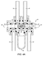
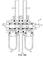
- the valve 36 comprises a valve body 60, which defines a substantially cylindrical valve chamber 62.
- the valve body 60 defines a return inlet port 64, a return operating port 66, an exhaust port 68, a drive operating port 70 and a drive inlet port 72, arranged consecutively with respect to the longitudinal axis of the valve chamber 62.
- the pressure inlet conduit 48 which is connected to the regulator 22, bifurcates between the regulator 22 and the valve 36, such that a drive inlet conduit 52 is connected to the drive inlet port 72 and a return inlet conduit 54 is connected to the return inlet port 64.
- the exhaust 50 is connected to the exhaust port 68.
- a drive spool 56 and a return spool 58 are each moveable within the valve 36 to actuate the valve 36.
- the drive trigger 18 is connected to the drive spool 56
- the return trigger 20 is connected to the return spool 58 by respective mechanical links, which cause each spool to move as each respective trigger is depressed.
- the drive spool 56 and the return spool 58 are situated in the valve chamber 62 and are moveable within the valve chamber 62 substantially along the longitudinal axis of the valve chamber 62. Each spool extends through a respective aperture in the valve body 60 at opposite ends of the valve chamber 62 along the longitudinal axis.
- a spring 74 is situated within the valve chamber 62 between the drive spool 56 and the return spool 58. The spring 74 is in compression and exerts a force on the spools which acts to move them apart.
- a maximum separation distance of the drive spool 56 and the return spool 58 is defined by a first stop 76 and a second stop 78, each defined by the valve body 60, and each acting to prevent movement of the drive spool 56 and the return spool 58, respectively, beyond a maximum separation distance.
- Each spool comprises lands and grooves as shown, for example, in Figure 4A .
- a plurality of O-rings 80 are positioned in the valve chamber 62 as shown, for example, in Figure 4A to define adjacent regions of space along the valve chamber 62 between pairs of the O-rings 80.
- Each region of space contains one of the five ports.
- Each of the ports and each of the apertures through which the spools extend out of the valve body 60 are individually sealed by respective O-rings 80 to prevent fluid from escaping from or entering the valve chamber 62 other than through the valve ports.
- the spools 56, 58 are at their maximum separation distance, and are positioned such that fluidic communication between the return inlet port 64 and the return operating port 66 is prevented, fluidic communication between the return operating port 66 and the exhaust port 68 is enabled, fluidic communication between the exhaust port 68 and the drive operating port 70 is enabled, and fluidic communication between the drive operating port 70 and the drive inlet port 72 is prevented, connecting the cylinder 4 on either side of the piston 28 to the atmosphere, so that the piston is not driven.
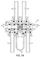
- the drive spool 56 has been moved by the drive trigger 18 from its position in the rest configuration towards the return spool 58 to abut the return spool 58.
- the spools are positioned such that fluidic communication between the return inlet port 64 and the return operating port 66 is prevented, fluidic communication between the return operating port 66 and the exhaust port 68 is enabled, fluidic communication between the exhaust port 68 and the drive operating port 70 is prevented, and fluidic communication between the drive operating port 70 and the drive inlet port 72 is enabled, connecting the drive operating port 70 to the regulator 22 to apply a drive pressure to cause the piston 28 and hence the rods 10 to advance.
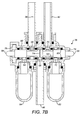
- the return spool 58 has been moved from its position in the rest configuration towards the drive spool 56 to abut the drive spool 56.
- the spools are positioned such that fluidic communication between the return inlet port 64 and the return operating port 66 is enabled, fluidic communication between the return operating port 66 and the exhaust port 68 is prevented, fluidic communication between the exhaust port 68 and the drive operating port 70 is enabled, and fluidic communication between the drive operating port 70 and the drive inlet port 72 is prevented, connecting the return operating port 66 to the regulator 22 to apply a return pressure to cause the piston 28 and, hence, the rods 10 to retreat.
- the drive spool 56 and the return spool 58 have each been moved by the same distance away from their position in the rest configuration towards each other until the spools abut each other.
- the spools are positioned such that fluidic communication between all of the ports is enabled.
- a substantial increase in pressure in the drive chamber 30 and/or the return chamber 34 is prevented by enabling fluidic communication between the drive chamber 30, the return chamber 34, the pressure inlet conduit 48 and the exhaust 50, causing pressurised fluid from the regulator 22 to vent through the exhaust 50.
- the above described specific embodiment is manufactured from a combination of metal for the cylinder 4, the rods 10 and the cartridge holder 8 and plastic materials for the remaining structural components including the stock portion 6.
- the cylinder 4 and end plates at the distal end of the cartridge holder 8 are made of aluminium, and the rods 10 and the remainder of the cartridge holder 8 are made of steel.
- the plastic materials used are nylon or acetal, with glass fillers where required. It will be understood that any suitable combination of these materials, including construction with all structural parts made from plastic materials can be used in alternative embodiments. Numerous materials are suitable for use in the sealing parts such as O-rings, for pressure connecting hoses and tubes and other pneumatic components such as valves and connectors, as is well know to the person skilled in the art.
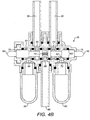
- a dual exhaust embodiment is similar to the embodiment described above, with the main differences between the embodiments being that the dispenser 2 comprises a drive exhaust 82 arranged to relieve pressure from the drive chamber 30 and a return exhaust 84 arranged to relieve pressure from the return chamber 34, and that the pressure inlet conduit does not bifurcate, but has a common pressure inlet conduit 86 connected to one port of the valve 36, selectively in fluidic communication with the drive chamber 30 and the return chamber 34 via the drive conduit 40 and the return conduit 38, respectively.
- the lands and grooves of the spools are arranged differently from the specific embodiment described above, as shown, for example, in Figure 4B , as a consequence of the different roles of the ports from one end of the valve 36 to the other.
- the connections of the return operating port 66 and the drive operating port 70 are the same as in the embodiment described above, but the return exhaust 84 is connected to the return inlet port 64, which now acts as a return exhaust port, the common pressure inlet conduit 86 is connected to the exhaust port 68, which now acts as a common inlet port, and the drive exhaust 82 is connected to the drive inlet port 72, which now acts as a drive exhaust port.
- the spools are arranged such that the drive and return ports are connected to their respective exhaust ports in the rest configuration, the drive port is connected to the common inlet and disconnected from its exhaust port in the drive configuration, and analogously for the return port in the return configuration. As for the specific embodiment described above, all ports are connected in the free flow configuration.
- the drive trigger 18 and the return trigger 20 are arranged the other way around, such that actuation of the trigger closer to the cylinder 4 causes the rods 10 to advance, and actuation of the trigger further from the cylinder 4 causes the rods 10 to retreat. In some embodiments, this is achieved by altering the mechanical links between the triggers and the valve 36, while in other embodiments, this is achieved by connecting the second drive conduit portion 46 to the conduit portion that is in fluidic communication with the return operating port 66 of the valve 36 (which then acts as a drive port), rather than the drive operating port 70 of the valve 36 (which then acts as a return port).
- the drive conduit 40 comprises a flexible (e.g. coiled) tube attached to an aperture in the piston 28 instead of the second drive conduit portion 46 extending through an aperture in the piston 28 as described with reference to Figure 2 .
- the flexibility of the tube allows the connection with the piston 28 to remain in place as the piston 28 moves relative to the cylinder 4.
- the exact fashion of conducting pressurised fluid from one side of the piston to the other need not be crucial, as long as the conduit is arranged to enable pressurised fluid to flow through the piston 28 to the drive chamber 30.
- the fluidic communication relationships between the ports are the same as the fluidic communication relationships described above for the rest configuration, e.g, for the specific embodiment described above with respect to Figure 4A , fluidic communication between the return inlet port 64 and the return operating port 66 is prevented, and fluidic communication between the drive operating port 70 and the drive inlet port 72 is prevented.
- the dispenser 2 comprises other kinds of holders, such as a holder to allow viscous material to be dispensed from a foil pack.
- the drive spool 56 and the return spool 58 are biased apart by any kind of biasing means such as a resilient polymeric member.
- the valve has a different number of ports, in some embodiments, and in particular, in some embodiments, the valve has at least six ports, such that the drive conduit and the return conduit are each selectively in fluidic communication with their own dedicated inlet and exhaust.
- the wall of the cylinder 4 of the specific embodiment described above has an annular cross-section
- the cylinder 4 has a different cross-section, for example a non-annular cross-section, such as those defining a chamber of an ellipsoid or a polygonal (rounded or not) cross-section.
- the dispenser 2 comprises a drive regulator and a return regulator, for regulating the supply of pressurised fluid to the drive chamber 30 and the return chamber 34, respectively in the respect drive and return configurations, rather than a single regulator.
- the drive regulator is in fluidic communication with a port of the valve 36 via a drive inlet conduit
- the return regulator is in fluidic communication with another port of the valve 36 via a return inlet conduit.
- the regulator is arranged such that the pressure applied to the drive chamber 30 in the drive configuration is higher than the pressure applied to the return chamber 34 in the return configuration.
- each regulator has its own dial for changing the amount of pressure applied to the respective chamber.
- the dispenser 2 comprises a valve arrangement with more than one valve, rather than with a single valve as described above.
- one of the valves is a drive valve, which controls the application of pressure to the drive chamber 30, and another valve is a return valve, which controls the application of pressure to the return chamber 34.
Landscapes
- Engineering & Computer Science (AREA)
- Mechanical Engineering (AREA)
- Coating Apparatus (AREA)
- Reciprocating Pumps (AREA)
- Manipulator (AREA)
Priority Applications (7)
| Application Number | Priority Date | Filing Date | Title |
|---|---|---|---|
| EP20100196812 EP2468419B1 (en) | 2010-12-23 | 2010-12-23 | Bi-directional pneumatic dispenser |
| PT101968121T PT2468419E (pt) | 2010-12-23 | 2010-12-23 | Aplicador pneumático bidirecional |
| PL10196812T PL2468419T3 (pl) | 2010-12-23 | 2010-12-23 | Dwukierunkowy dozownik pneumatyczny |
| DK10196812T DK2468419T3 (en) | 2010-12-23 | 2010-12-23 | Bi-directional trykluftdispenser |
| ES10196812.1T ES2534307T3 (es) | 2010-12-23 | 2010-12-23 | Dispensador neumático bidireccional |
| AU2011253920A AU2011253920B2 (en) | 2010-12-23 | 2011-12-08 | Dispenser |
| US13/336,517 US8616415B2 (en) | 2010-12-23 | 2011-12-23 | Dispenser |
Applications Claiming Priority (1)
| Application Number | Priority Date | Filing Date | Title |
|---|---|---|---|
| EP20100196812 EP2468419B1 (en) | 2010-12-23 | 2010-12-23 | Bi-directional pneumatic dispenser |
Publications (2)
| Publication Number | Publication Date |
|---|---|
| EP2468419A1 EP2468419A1 (en) | 2012-06-27 |
| EP2468419B1 true EP2468419B1 (en) | 2015-01-21 |
Family
ID=44146358
Family Applications (1)
| Application Number | Title | Priority Date | Filing Date |
|---|---|---|---|
| EP20100196812 Active EP2468419B1 (en) | 2010-12-23 | 2010-12-23 | Bi-directional pneumatic dispenser |
Country Status (7)
| Country | Link |
|---|---|
| US (1) | US8616415B2 (es) |
| EP (1) | EP2468419B1 (es) |
| AU (1) | AU2011253920B2 (es) |
| DK (1) | DK2468419T3 (es) |
| ES (1) | ES2534307T3 (es) |
| PL (1) | PL2468419T3 (es) |
| PT (1) | PT2468419E (es) |
Families Citing this family (7)
| Publication number | Priority date | Publication date | Assignee | Title |
|---|---|---|---|---|
| BR112013004173A2 (pt) * | 2010-08-25 | 2019-09-24 | Basf Se | pistola de pulverização para expulsão de fluídos |
| US8991651B2 (en) * | 2012-01-23 | 2015-03-31 | Patent & Investment Llc | Reconfigurable applicator system having combination trigger actuation |
| US20140166768A1 (en) * | 2012-12-19 | 2014-06-19 | Dow Agrosciences Llc | Automated device for the application of agricultural management materials |
| ES2726179T3 (es) | 2014-03-24 | 2019-10-02 | Sulzer Mixpac Ag | Dispensador |
| GB2530476A (en) | 2014-07-15 | 2016-03-30 | Cox Ltd | Multicomponent dispenser |
| ES2750849T3 (es) * | 2015-09-22 | 2020-03-27 | Dow Global Technologies Llc | Dispensador de espuma de poliuretano pulverizado de dos componentes con purgado continuo de gas |
| EP3251756A1 (en) | 2016-05-31 | 2017-12-06 | Sulzer Mixpac AG | Housing and dispenser |
Family Cites Families (82)
| Publication number | Priority date | Publication date | Assignee | Title |
|---|---|---|---|---|
| US2388662A (en) * | 1941-12-09 | 1945-11-13 | Western Electric Co | Liquid measuring apparatus |
| US2582156A (en) | 1948-03-20 | 1952-01-08 | Wilbur P Peterson | Dispensing apparatus and cartridge therefor |
| FR984352A (fr) | 1949-04-08 | 1951-07-05 | Approvisionnement General Pour | Pistolet doseur pour la distribution de liquides, émulsions et suspensions |
| US2692706A (en) * | 1950-07-27 | 1954-10-26 | Wiksten Carl Jay | Air pressure caulking gun |
| US2705463A (en) | 1954-04-21 | 1955-04-05 | William V Moore | Pastry decorator |
| BE548210A (es) | 1955-01-14 | |||
| CH329614A (fr) | 1955-06-03 | 1958-04-30 | Maillard Jules | Appareil pour le mélange de proportions déterminées de matériaux |
| US2839945A (en) | 1957-02-13 | 1958-06-24 | Zion Benson | Control device |
| DK116620B (da) * | 1963-05-30 | 1970-01-26 | N Madsen | Kraftdrevet håndsprøjte, især til plastiske masser såsom kit. |
| NL6602366A (es) | 1965-02-25 | 1966-08-26 | ||
| US3431953A (en) * | 1966-05-25 | 1969-03-11 | Russell G Rutherford | Measured liquid dispenser |
| US3559687A (en) * | 1968-04-01 | 1971-02-02 | Alkon Products Corp | Fluid valve construction |
| DE1784336A1 (de) | 1968-07-29 | 1971-08-19 | Helmut Roos | Spritzpistole zum Ausfugen und Verspachteln von Fertigteilelementen und sonstigen Flaechen und Fugen |
| US3740612A (en) | 1971-05-28 | 1973-06-19 | Champion Spark Plug Co | Apparatus for coating with electrostatically charged particulate materials |
| US3780384A (en) * | 1972-01-17 | 1973-12-25 | G Rivelle | Automatic toilet flushing system |
| US3768472A (en) | 1972-02-07 | 1973-10-30 | M Hodosh | Fluid dispensing gun |
| SE371942B (es) | 1972-03-13 | 1974-12-09 | Atlas Copco Ab | |
| US3980209A (en) | 1973-12-10 | 1976-09-14 | Roean Industries | Bulk loading plastic compound dispensing device |
| US4029236A (en) | 1976-05-17 | 1977-06-14 | Colgate-Palmolive Company | Two product dispenser with cooperating telescoping cylinders |
| GB1555455A (en) | 1976-06-11 | 1979-11-07 | Cox Mastic Appliances Ltd P C | Dispensing gun |
| US4290091A (en) | 1976-12-27 | 1981-09-15 | Speeflo Manufacturing Corporation | Spray gun having self-contained low voltage and high voltage power supplies |
| GB1589381A (en) | 1977-07-18 | 1981-05-13 | Cox Newbury Ltd | Pneumatic dispensers for viscous materials |
| US4264021A (en) | 1978-02-08 | 1981-04-28 | Davis George B Jun | Hand held electric caulking gun |
| US4171072A (en) | 1978-02-08 | 1979-10-16 | Geo B. Davis, Jr. | Hand held electric caulking gun |
| US4273269A (en) | 1978-02-08 | 1981-06-16 | Davis George B Jun | Hand held electric caulking gun |
| US4366919A (en) | 1978-05-01 | 1983-01-04 | Coaxial Cartridges, Inc. | Composite cartridge and device for metering extrusion of contents |
| US4174068A (en) | 1978-11-07 | 1979-11-13 | Rudolph Robert L | Gun having disposable cartridge |
| US4322022A (en) | 1980-03-19 | 1982-03-30 | Whirlco, Inc. | Quick release for helically-threaded drive unit |
| DE3031939A1 (de) | 1980-08-25 | 1982-04-01 | Hilti AG, 9494 Schaan | Auspressgeraet fuer fliessfaehige massen |
| US4376498A (en) * | 1980-10-02 | 1983-03-15 | Davis George B Jun | Hand-held pneumatic caulking gun |
| US4472141A (en) | 1981-10-26 | 1984-09-18 | Dragan William B | All purpose dental syringe |
| DE3420324A1 (de) | 1984-05-30 | 1985-12-05 | Lechler Chemie Gmbh, 7000 Stuttgart | Abgabevorrichtung fuer mehrere stroemungsfaehige materialkomponenten |
| ES2020583B3 (es) | 1987-01-26 | 1991-08-16 | Wilhelm A Keller | Aparato de distribucion accionado por medio de presion al servicio de cartuchos dobles. |
| US4757628A (en) | 1987-03-27 | 1988-07-19 | Bulfer Gary M | Shark saber |
| US5020693A (en) * | 1989-06-30 | 1991-06-04 | Illinois Tool Works Inc. | Dosage control for adhesive dispenser |
| US5127552A (en) * | 1989-08-24 | 1992-07-07 | Dow Corning Corporation | Foam mixer-applicator with foaming chamber and method of using |
| USD329277S (en) | 1989-12-14 | 1992-09-08 | Keske David G | Urethane foam gun |
| DE59006902D1 (de) | 1990-01-05 | 1994-09-29 | Maderag Ag Pfaeffikon | Ausdrückpistole für Doppelwandkartuschen. |
| DE9011965U1 (es) | 1990-08-17 | 1990-10-18 | Deutsche Tecalemit Gmbh, 4800 Bielefeld, De | |
| DE9000957U1 (es) | 1990-01-29 | 1990-04-05 | Deutsche Tecalemit Gmbh, 4800 Bielefeld, De | |
| US5064098A (en) * | 1990-02-23 | 1991-11-12 | Physical Systems, Inc. | Dual component dispenser gun |
| GB9006391D0 (en) | 1990-03-22 | 1990-05-23 | Bba Group Plc | Dispensing gun |
| US5163584A (en) * | 1990-12-18 | 1992-11-17 | Polyfoam Products, Inc. | Method and apparatus for mixing and dispensing foam with injected low pressure gas |
| US5125836A (en) | 1991-02-04 | 1992-06-30 | Centrix, Inc. | Easy loading manual extruder for viscous material |
| US5301842A (en) | 1991-03-06 | 1994-04-12 | Frank Ritter | Multicomponent cartridge for plastic materials |
| IT1253315B (it) | 1991-07-29 | 1995-07-14 | A N I Spa Off Mec | Dispositivo per l'erogazione di prodotti fluidi e/o semifluidi |
| GB9200663D0 (en) | 1992-01-14 | 1992-03-11 | Bba Group Plc | Dispenser for viscous material and controller therefor |
| US5277099A (en) * | 1992-06-25 | 1994-01-11 | Graco Inc. | Reduced icing low friction air valve |
| DE4231418A1 (de) | 1992-09-19 | 1994-03-24 | Hilti Ag | Vorschubmechanismus eines Auspressgerätes |
| DE9304337U1 (de) | 1993-03-23 | 1994-07-28 | Prestele Eugen | Kartusche |
| US5489207A (en) | 1993-11-04 | 1996-02-06 | Centrix, Inc. | Dental cartridge extruder with rigid drop-in front end |
| US5536531A (en) | 1994-07-26 | 1996-07-16 | Minnesota Mining And Manufacturing Company | Applicator for shear thinning viscous coating materials |
| USD394994S (en) | 1996-10-17 | 1998-06-09 | Dreve-Otoplastik Gmbh | Device for pressing cartridges |
| JP3478319B2 (ja) | 1996-12-03 | 2003-12-15 | 藤倉ゴム工業株式会社 | ディスペンサ装置 |
| US5860739A (en) | 1997-03-05 | 1999-01-19 | Cannon; Mark L. | Automatic mixing syringe for dental materials |
| USD411421S (en) | 1998-01-19 | 1999-06-22 | Sofragraf Industries | Hot melt gun |
| DE19806256C1 (de) | 1998-02-17 | 1999-05-12 | Heraeus Kulzer Gmbh | Manuell bedienbare Ejektoreinrichtung zur Aufnahme einer Kartusche |
| AUPP719798A0 (en) | 1998-11-19 | 1998-12-17 | Ramset Fasteners (Aust.) Pty. Limited | A cartridge dispensing gun |
| US6135328A (en) * | 1999-05-19 | 2000-10-24 | Schneider; Mark C. | Pressure relief mechanism for a dispensing device |
| US6439439B1 (en) | 2001-01-12 | 2002-08-27 | Telios Orthopedic Systems, Inc. | Bone cement delivery apparatus and hand-held fluent material dispensing apparatus |
| AU2002231604A1 (en) | 2001-02-14 | 2002-08-28 | Jorn Ronvig | Dental extruder system |
| DE10128611A1 (de) | 2001-06-13 | 2002-12-19 | Fischer Artur Werke Gmbh | Ausdrückvorrichtung für eine zwei konzentrisch zueinander angeordnete Kammern aufweisende Kartusche |
| US6401988B1 (en) | 2001-10-01 | 2002-06-11 | Rodger G. Parent | Retrofit friction pad for fluid material dispenser |
| US6412667B1 (en) | 2001-10-09 | 2002-07-02 | Kai Shyun Enterprise Co., Ltd. | Glue dispensing gun |
| USD479305S1 (en) | 2002-10-22 | 2003-09-02 | Graco Minnesota Inc. | Plural component spray gun |
| US6929157B2 (en) | 2003-02-26 | 2005-08-16 | Confi-Dental Products Co. | Multiple use dental viscous material dispenser |
| WO2005095225A1 (en) | 2004-04-01 | 2005-10-13 | 5 Mix Limited | Dispenser for two components and method for dispensing first and second components |
| USD541121S1 (en) | 2004-11-18 | 2007-04-24 | Hyperion Innovations, Inc. | Liquid dispensing apparatus |
| FR2884137B1 (fr) | 2005-04-06 | 2008-02-15 | Prod Dentaires Pierre Rolland | Dispositif medical d'extrusion de matieres liquides ou pateuses |
| US7334709B1 (en) * | 2005-06-13 | 2008-02-26 | Kai Shyun Enterprise Co., Ltd. | Pneumatic caulking gun |
| DE102005038621B4 (de) | 2005-08-16 | 2007-09-13 | Bosch Rexroth Ag | Pneumatisches Wegeventil mit mindestens einem Ventilschieber |
| US7971758B2 (en) | 2005-11-10 | 2011-07-05 | Black & Decker Inc. | Caulk gun |
| US8469063B2 (en) | 2006-12-20 | 2013-06-25 | Pro Form Products Limited | Filling head injector for aerosol can |
| TWI332851B (en) | 2007-04-27 | 2010-11-11 | Dermato Plastica Beauty Dpb Co Ltd | Volume adjustable, micro-injection device |
| USD608858S1 (en) | 2008-03-10 | 2010-01-26 | Illinois Tool Works Inc. | Coating material dispensing device |
| USD588231S1 (en) | 2008-05-21 | 2009-03-10 | Pellin Christopher J | Spray applicator |
| GB0918585D0 (en) | 2009-10-22 | 2009-12-09 | Cox Ltd | Plunger |
| KR101088292B1 (ko) | 2009-10-30 | 2011-11-30 | 조성용 | 이액형 점성유체 압출건 |
| USD649221S1 (en) | 2009-11-23 | 2011-11-22 | Graco Minnesota Inc. | Fiberglass spraying apparatus |
| USD660105S1 (en) | 2010-12-23 | 2012-05-22 | Richard Brummitt | Dispenser for cartridge |
| EP2468417A1 (en) | 2010-12-23 | 2012-06-27 | P C Cox Limited | Actuator for a cartridge dispenser |
| USD660663S1 (en) | 2010-12-23 | 2012-05-29 | P.C. Cox Limited | Dual trigger dispenser for cartridge |
-
2010
- 2010-12-23 DK DK10196812T patent/DK2468419T3/en active
- 2010-12-23 ES ES10196812.1T patent/ES2534307T3/es active Active
- 2010-12-23 PL PL10196812T patent/PL2468419T3/pl unknown
- 2010-12-23 PT PT101968121T patent/PT2468419E/pt unknown
- 2010-12-23 EP EP20100196812 patent/EP2468419B1/en active Active
-
2011
- 2011-12-08 AU AU2011253920A patent/AU2011253920B2/en not_active Ceased
- 2011-12-23 US US13/336,517 patent/US8616415B2/en active Active
Also Published As
| Publication number | Publication date |
|---|---|
| EP2468419A1 (en) | 2012-06-27 |
| PT2468419E (pt) | 2015-05-13 |
| US8616415B2 (en) | 2013-12-31 |
| AU2011253920B2 (en) | 2014-03-27 |
| AU2011253920A1 (en) | 2012-07-12 |
| ES2534307T3 (es) | 2015-04-21 |
| DK2468419T3 (en) | 2015-04-13 |
| PL2468419T3 (pl) | 2015-06-30 |
| US20120160876A1 (en) | 2012-06-28 |
Similar Documents
| Publication | Publication Date | Title |
|---|---|---|
| US8616415B2 (en) | Dispenser | |
| EP2468414B1 (en) | Pneumatic dispenser | |
| US20230349665A1 (en) | Compressed gas gun | |
| JP6277533B2 (ja) | 水分配装置のコントローラ | |
| US3813012A (en) | Air powered sealant dispenser, including flexible tubular conduits as valve means | |
| EP2565512B1 (en) | Grease gun | |
| US8607824B2 (en) | Valve and dispenser using the valve | |
| CN111629840B (zh) | 气动材料喷枪 | |
| EP0840562A4 (en) | DISPENSER FOR MULTIPLE SUBSTANCES | |
| US3603487A (en) | In-line sealant dispenser | |
| CN111050922B (zh) | 具有改进的扳机组件的无气喷枪 | |
| EP3064884B1 (en) | A gas powered gun | |
| US6234359B1 (en) | System for reloading dispensing tools | |
| US6631531B1 (en) | Quick load air gun | |
| US20120292339A1 (en) | Dispensing gun for a collapsible adhesive-filled container | |
| US9417031B2 (en) | Device for controlling the impulsive feeding of a pressurized fluid and an air weapon comprising such device | |
| US4338066A (en) | Grease gun | |
| WO2016178587A1 (en) | A pneumatic or hydraulic mechanism | |
| JP2013043142A (ja) | ロング仕様のシーラガン |
Legal Events
| Date | Code | Title | Description |
|---|---|---|---|
| 17P | Request for examination filed |
Effective date: 20111125 |
|
| AK | Designated contracting states |
Kind code of ref document: A1 Designated state(s): AL AT BE BG CH CY CZ DE DK EE ES FI FR GB GR HR HU IE IS IT LI LT LU LV MC MK MT NL NO PL PT RO RS SE SI SK SM TR |
|
| AX | Request for extension of the european patent |
Extension state: BA ME |
|
| PUAI | Public reference made under article 153(3) epc to a published international application that has entered the european phase |
Free format text: ORIGINAL CODE: 0009012 |
|
| GRAP | Despatch of communication of intention to grant a patent |
Free format text: ORIGINAL CODE: EPIDOSNIGR1 |
|
| INTG | Intention to grant announced |
Effective date: 20140818 |
|
| GRAS | Grant fee paid |
Free format text: ORIGINAL CODE: EPIDOSNIGR3 |
|
| GRAA | (expected) grant |
Free format text: ORIGINAL CODE: 0009210 |
|
| AK | Designated contracting states |
Kind code of ref document: B1 Designated state(s): AL AT BE BG CH CY CZ DE DK EE ES FI FR GB GR HR HU IE IS IT LI LT LU LV MC MK MT NL NO PL PT RO RS SE SI SK SM TR |
|
| REG | Reference to a national code |
Ref country code: GB Ref legal event code: FG4D |
|
| REG | Reference to a national code |
Ref country code: CH Ref legal event code: EP |
|
| REG | Reference to a national code |
Ref country code: IE Ref legal event code: FG4D |
|
| REG | Reference to a national code |
Ref country code: DE Ref legal event code: R096 Ref document number: 602010021920 Country of ref document: DE Effective date: 20150305 |
|
| REG | Reference to a national code |
Ref country code: AT Ref legal event code: REF Ref document number: 708906 Country of ref document: AT Kind code of ref document: T Effective date: 20150315 |
|
| REG | Reference to a national code |
Ref country code: DK Ref legal event code: T3 Effective date: 20150407 |
|
| REG | Reference to a national code |
Ref country code: NL Ref legal event code: T3 |
|
| REG | Reference to a national code |
Ref country code: ES Ref legal event code: FG2A Ref document number: 2534307 Country of ref document: ES Kind code of ref document: T3 Effective date: 20150421 |
|
| REG | Reference to a national code |
Ref country code: NL Ref legal event code: T3 |
|
| REG | Reference to a national code |
Ref country code: NL Ref legal event code: T3 |
|
| REG | Reference to a national code |
Ref country code: PT Ref legal event code: SC4A Free format text: AVAILABILITY OF NATIONAL TRANSLATION Effective date: 20150415 |
|
| REG | Reference to a national code |
Ref country code: LT Ref legal event code: MG4D |
|
| REG | Reference to a national code |
Ref country code: PL Ref legal event code: T3 |
|
| PG25 | Lapsed in a contracting state [announced via postgrant information from national office to epo] |
Ref country code: LT Free format text: LAPSE BECAUSE OF FAILURE TO SUBMIT A TRANSLATION OF THE DESCRIPTION OR TO PAY THE FEE WITHIN THE PRESCRIBED TIME-LIMIT Effective date: 20150121 Ref country code: BG Free format text: LAPSE BECAUSE OF FAILURE TO SUBMIT A TRANSLATION OF THE DESCRIPTION OR TO PAY THE FEE WITHIN THE PRESCRIBED TIME-LIMIT Effective date: 20150421 Ref country code: HR Free format text: LAPSE BECAUSE OF FAILURE TO SUBMIT A TRANSLATION OF THE DESCRIPTION OR TO PAY THE FEE WITHIN THE PRESCRIBED TIME-LIMIT Effective date: 20150121 Ref country code: NO Free format text: LAPSE BECAUSE OF FAILURE TO SUBMIT A TRANSLATION OF THE DESCRIPTION OR TO PAY THE FEE WITHIN THE PRESCRIBED TIME-LIMIT Effective date: 20150421 Ref country code: FI Free format text: LAPSE BECAUSE OF FAILURE TO SUBMIT A TRANSLATION OF THE DESCRIPTION OR TO PAY THE FEE WITHIN THE PRESCRIBED TIME-LIMIT Effective date: 20150121 Ref country code: SE Free format text: LAPSE BECAUSE OF FAILURE TO SUBMIT A TRANSLATION OF THE DESCRIPTION OR TO PAY THE FEE WITHIN THE PRESCRIBED TIME-LIMIT Effective date: 20150121 |
|
| PG25 | Lapsed in a contracting state [announced via postgrant information from national office to epo] |
Ref country code: RS Free format text: LAPSE BECAUSE OF FAILURE TO SUBMIT A TRANSLATION OF THE DESCRIPTION OR TO PAY THE FEE WITHIN THE PRESCRIBED TIME-LIMIT Effective date: 20150121 Ref country code: GR Free format text: LAPSE BECAUSE OF FAILURE TO SUBMIT A TRANSLATION OF THE DESCRIPTION OR TO PAY THE FEE WITHIN THE PRESCRIBED TIME-LIMIT Effective date: 20150422 Ref country code: IS Free format text: LAPSE BECAUSE OF FAILURE TO SUBMIT A TRANSLATION OF THE DESCRIPTION OR TO PAY THE FEE WITHIN THE PRESCRIBED TIME-LIMIT Effective date: 20150521 Ref country code: LV Free format text: LAPSE BECAUSE OF FAILURE TO SUBMIT A TRANSLATION OF THE DESCRIPTION OR TO PAY THE FEE WITHIN THE PRESCRIBED TIME-LIMIT Effective date: 20150121 |
|
| REG | Reference to a national code |
Ref country code: DE Ref legal event code: R097 Ref document number: 602010021920 Country of ref document: DE |
|
| PG25 | Lapsed in a contracting state [announced via postgrant information from national office to epo] |
Ref country code: EE Free format text: LAPSE BECAUSE OF FAILURE TO SUBMIT A TRANSLATION OF THE DESCRIPTION OR TO PAY THE FEE WITHIN THE PRESCRIBED TIME-LIMIT Effective date: 20150121 Ref country code: SK Free format text: LAPSE BECAUSE OF FAILURE TO SUBMIT A TRANSLATION OF THE DESCRIPTION OR TO PAY THE FEE WITHIN THE PRESCRIBED TIME-LIMIT Effective date: 20150121 Ref country code: RO Free format text: LAPSE BECAUSE OF FAILURE TO SUBMIT A TRANSLATION OF THE DESCRIPTION OR TO PAY THE FEE WITHIN THE PRESCRIBED TIME-LIMIT Effective date: 20150121 Ref country code: CZ Free format text: LAPSE BECAUSE OF FAILURE TO SUBMIT A TRANSLATION OF THE DESCRIPTION OR TO PAY THE FEE WITHIN THE PRESCRIBED TIME-LIMIT Effective date: 20150121 |
|
| REG | Reference to a national code |
Ref country code: FR Ref legal event code: PLFP Year of fee payment: 6 |
|
| PLBE | No opposition filed within time limit |
Free format text: ORIGINAL CODE: 0009261 |
|
| STAA | Information on the status of an ep patent application or granted ep patent |
Free format text: STATUS: NO OPPOSITION FILED WITHIN TIME LIMIT |
|
| 26N | No opposition filed |
Effective date: 20151022 |
|
| PG25 | Lapsed in a contracting state [announced via postgrant information from national office to epo] |
Ref country code: SI Free format text: LAPSE BECAUSE OF FAILURE TO SUBMIT A TRANSLATION OF THE DESCRIPTION OR TO PAY THE FEE WITHIN THE PRESCRIBED TIME-LIMIT Effective date: 20150121 |
|
| REG | Reference to a national code |
Ref country code: AT Ref legal event code: UEP Ref document number: 708906 Country of ref document: AT Kind code of ref document: T Effective date: 20150121 |
|
| PG25 | Lapsed in a contracting state [announced via postgrant information from national office to epo] |
Ref country code: LU Free format text: LAPSE BECAUSE OF FAILURE TO SUBMIT A TRANSLATION OF THE DESCRIPTION OR TO PAY THE FEE WITHIN THE PRESCRIBED TIME-LIMIT Effective date: 20151223 Ref country code: MC Free format text: LAPSE BECAUSE OF FAILURE TO SUBMIT A TRANSLATION OF THE DESCRIPTION OR TO PAY THE FEE WITHIN THE PRESCRIBED TIME-LIMIT Effective date: 20150121 |
|
| REG | Reference to a national code |
Ref country code: CH Ref legal event code: PL |
|
| REG | Reference to a national code |
Ref country code: DE Ref legal event code: R082 Ref document number: 602010021920 Country of ref document: DE Representative=s name: MANITZ FINSTERWALD PATENT- UND RECHTSANWALTSPA, DE Ref country code: DE Ref legal event code: R082 Ref document number: 602010021920 Country of ref document: DE Representative=s name: MANITZ FINSTERWALD PATENTANWAELTE PARTMBB, DE Ref country code: DE Ref legal event code: R082 Ref document number: 602010021920 Country of ref document: DE Representative=s name: MANITZ, FINSTERWALD & PARTNER GBR, DE |
|
| PG25 | Lapsed in a contracting state [announced via postgrant information from national office to epo] |
Ref country code: CH Free format text: LAPSE BECAUSE OF NON-PAYMENT OF DUE FEES Effective date: 20151231 Ref country code: LI Free format text: LAPSE BECAUSE OF NON-PAYMENT OF DUE FEES Effective date: 20151231 |
|
| REG | Reference to a national code |
Ref country code: FR Ref legal event code: PLFP Year of fee payment: 7 |
|
| PG25 | Lapsed in a contracting state [announced via postgrant information from national office to epo] |
Ref country code: SM Free format text: LAPSE BECAUSE OF FAILURE TO SUBMIT A TRANSLATION OF THE DESCRIPTION OR TO PAY THE FEE WITHIN THE PRESCRIBED TIME-LIMIT Effective date: 20150121 Ref country code: HU Free format text: LAPSE BECAUSE OF FAILURE TO SUBMIT A TRANSLATION OF THE DESCRIPTION OR TO PAY THE FEE WITHIN THE PRESCRIBED TIME-LIMIT; INVALID AB INITIO Effective date: 20101223 |
|
| PG25 | Lapsed in a contracting state [announced via postgrant information from national office to epo] |
Ref country code: CY Free format text: LAPSE BECAUSE OF FAILURE TO SUBMIT A TRANSLATION OF THE DESCRIPTION OR TO PAY THE FEE WITHIN THE PRESCRIBED TIME-LIMIT Effective date: 20150121 |
|
| PG25 | Lapsed in a contracting state [announced via postgrant information from national office to epo] |
Ref country code: MT Free format text: LAPSE BECAUSE OF FAILURE TO SUBMIT A TRANSLATION OF THE DESCRIPTION OR TO PAY THE FEE WITHIN THE PRESCRIBED TIME-LIMIT Effective date: 20150121 Ref country code: TR Free format text: LAPSE BECAUSE OF FAILURE TO SUBMIT A TRANSLATION OF THE DESCRIPTION OR TO PAY THE FEE WITHIN THE PRESCRIBED TIME-LIMIT Effective date: 20150121 |
|
| REG | Reference to a national code |
Ref country code: FR Ref legal event code: PLFP Year of fee payment: 8 |
|
| PGFP | Annual fee paid to national office [announced via postgrant information from national office to epo] |
Ref country code: DK Payment date: 20171215 Year of fee payment: 8 |
|
| PGFP | Annual fee paid to national office [announced via postgrant information from national office to epo] |
Ref country code: IE Payment date: 20171221 Year of fee payment: 8 Ref country code: PL Payment date: 20171127 Year of fee payment: 8 Ref country code: BE Payment date: 20171219 Year of fee payment: 8 Ref country code: PT Payment date: 20171221 Year of fee payment: 8 Ref country code: AT Payment date: 20171221 Year of fee payment: 8 |
|
| PG25 | Lapsed in a contracting state [announced via postgrant information from national office to epo] |
Ref country code: MK Free format text: LAPSE BECAUSE OF FAILURE TO SUBMIT A TRANSLATION OF THE DESCRIPTION OR TO PAY THE FEE WITHIN THE PRESCRIBED TIME-LIMIT Effective date: 20150121 |
|
| PG25 | Lapsed in a contracting state [announced via postgrant information from national office to epo] |
Ref country code: AL Free format text: LAPSE BECAUSE OF FAILURE TO SUBMIT A TRANSLATION OF THE DESCRIPTION OR TO PAY THE FEE WITHIN THE PRESCRIBED TIME-LIMIT Effective date: 20150121 |
|
| REG | Reference to a national code |
Ref country code: DE Ref legal event code: R081 Ref document number: 602010021920 Country of ref document: DE Owner name: MEDMIX SWITZERLAND AG, CH Free format text: FORMER OWNER: P C COX LTD., NEWBURY, BERKSHIRE, GB Ref country code: DE Ref legal event code: R082 Ref document number: 602010021920 Country of ref document: DE Representative=s name: MANITZ FINSTERWALD PATENT- UND RECHTSANWALTSPA, DE Ref country code: DE Ref legal event code: R082 Ref document number: 602010021920 Country of ref document: DE Representative=s name: MANITZ FINSTERWALD PATENTANWAELTE PARTMBB, DE Ref country code: DE Ref legal event code: R081 Ref document number: 602010021920 Country of ref document: DE Owner name: SULZER MIXPAC AG, CH Free format text: FORMER OWNER: P C COX LTD., NEWBURY, BERKSHIRE, GB |
|
| REG | Reference to a national code |
Ref country code: ES Ref legal event code: PC2A Owner name: SULZER MIXPAC AG Effective date: 20190513 |
|
| REG | Reference to a national code |
Ref country code: GB Ref legal event code: 732E Free format text: REGISTERED BETWEEN 20190516 AND 20190522 |
|
| REG | Reference to a national code |
Ref country code: NL Ref legal event code: PD Owner name: SULZER MIXPAC AG; CH Free format text: DETAILS ASSIGNMENT: CHANGE OF OWNER(S), ASSIGNMENT; FORMER OWNER NAME: SULZER MIXPAC (UK) LTD. Effective date: 20190514 Ref country code: NL Ref legal event code: HC Owner name: SULZER MIXPAC (UK) LTD.; GB Free format text: DETAILS ASSIGNMENT: CHANGE OF OWNER(S), CHANGE OF OWNER(S) NAME; FORMER OWNER NAME: P C COX LIMITED Effective date: 20190514 |
|
| REG | Reference to a national code |
Ref country code: DK Ref legal event code: EBP Effective date: 20181231 |
|
| PG25 | Lapsed in a contracting state [announced via postgrant information from national office to epo] |
Ref country code: PT Free format text: LAPSE BECAUSE OF NON-PAYMENT OF DUE FEES Effective date: 20190624 |
|
| REG | Reference to a national code |
Ref country code: AT Ref legal event code: MM01 Ref document number: 708906 Country of ref document: AT Kind code of ref document: T Effective date: 20181223 |
|
| REG | Reference to a national code |
Ref country code: IE Ref legal event code: MM4A |
|
| REG | Reference to a national code |
Ref country code: BE Ref legal event code: MM Effective date: 20181231 |
|
| PG25 | Lapsed in a contracting state [announced via postgrant information from national office to epo] |
Ref country code: IE Free format text: LAPSE BECAUSE OF NON-PAYMENT OF DUE FEES Effective date: 20181223 |
|
| PG25 | Lapsed in a contracting state [announced via postgrant information from national office to epo] |
Ref country code: BE Free format text: LAPSE BECAUSE OF NON-PAYMENT OF DUE FEES Effective date: 20181231 |
|
| PG25 | Lapsed in a contracting state [announced via postgrant information from national office to epo] |
Ref country code: AT Free format text: LAPSE BECAUSE OF NON-PAYMENT OF DUE FEES Effective date: 20181223 |
|
| PG25 | Lapsed in a contracting state [announced via postgrant information from national office to epo] |
Ref country code: DK Free format text: LAPSE BECAUSE OF NON-PAYMENT OF DUE FEES Effective date: 20181231 |
|
| PGFP | Annual fee paid to national office [announced via postgrant information from national office to epo] |
Ref country code: NL Payment date: 20191219 Year of fee payment: 10 |
|
| PG25 | Lapsed in a contracting state [announced via postgrant information from national office to epo] |
Ref country code: PL Free format text: LAPSE BECAUSE OF NON-PAYMENT OF DUE FEES Effective date: 20181223 |
|
| PGFP | Annual fee paid to national office [announced via postgrant information from national office to epo] |
Ref country code: IT Payment date: 20201224 Year of fee payment: 11 |
|
| PGFP | Annual fee paid to national office [announced via postgrant information from national office to epo] |
Ref country code: ES Payment date: 20210223 Year of fee payment: 11 |
|
| REG | Reference to a national code |
Ref country code: NL Ref legal event code: MM Effective date: 20210101 |
|
| PG25 | Lapsed in a contracting state [announced via postgrant information from national office to epo] |
Ref country code: NL Free format text: LAPSE BECAUSE OF NON-PAYMENT OF DUE FEES Effective date: 20210101 |
|
| REG | Reference to a national code |
Ref country code: DE Ref legal event code: R081 Ref document number: 602010021920 Country of ref document: DE Owner name: MEDMIX SWITZERLAND AG, CH Free format text: FORMER OWNER: SULZER MIXPAC AG, HAAG, CH |
|
| PG25 | Lapsed in a contracting state [announced via postgrant information from national office to epo] |
Ref country code: IT Free format text: LAPSE BECAUSE OF NON-PAYMENT OF DUE FEES Effective date: 20211223 |
|
| REG | Reference to a national code |
Ref country code: ES Ref legal event code: FD2A Effective date: 20230301 |
|
| PG25 | Lapsed in a contracting state [announced via postgrant information from national office to epo] |
Ref country code: ES Free format text: LAPSE BECAUSE OF NON-PAYMENT OF DUE FEES Effective date: 20211224 |
|
| PGFP | Annual fee paid to national office [announced via postgrant information from national office to epo] |
Ref country code: GB Payment date: 20231220 Year of fee payment: 14 |
|
| PGFP | Annual fee paid to national office [announced via postgrant information from national office to epo] |
Ref country code: FR Payment date: 20231221 Year of fee payment: 14 Ref country code: DE Payment date: 20231214 Year of fee payment: 14 |