EP2467983B1 - Procédé et appareil pour un récepteur de communication sans fil amélioré - Google Patents
Procédé et appareil pour un récepteur de communication sans fil amélioré Download PDFInfo
- Publication number
- EP2467983B1 EP2467983B1 EP10752934.9A EP10752934A EP2467983B1 EP 2467983 B1 EP2467983 B1 EP 2467983B1 EP 10752934 A EP10752934 A EP 10752934A EP 2467983 B1 EP2467983 B1 EP 2467983B1
- Authority
- EP
- European Patent Office
- Prior art keywords
- modem
- bit
- joint
- metric
- bits
- Prior art date
- Legal status (The legal status is an assumption and is not a legal conclusion. Google has not performed a legal analysis and makes no representation as to the accuracy of the status listed.)
- Not-in-force
Links
- 238000000034 method Methods 0.000 title claims description 29
- 238000004891 communication Methods 0.000 title claims description 13
- 238000012937 correction Methods 0.000 claims description 5
- 238000001514 detection method Methods 0.000 claims description 4
- 238000012545 processing Methods 0.000 description 27
- 238000013459 approach Methods 0.000 description 15
- 230000006870 function Effects 0.000 description 11
- 238000010586 diagram Methods 0.000 description 9
- 230000003993 interaction Effects 0.000 description 9
- 230000004927 fusion Effects 0.000 description 7
- 238000013507 mapping Methods 0.000 description 5
- 108091006146 Channels Proteins 0.000 description 4
- 230000008901 benefit Effects 0.000 description 4
- 230000005540 biological transmission Effects 0.000 description 4
- 230000007704 transition Effects 0.000 description 4
- 238000004422 calculation algorithm Methods 0.000 description 3
- 238000004590 computer program Methods 0.000 description 3
- 230000008878 coupling Effects 0.000 description 3
- 238000010168 coupling process Methods 0.000 description 3
- 238000005859 coupling reaction Methods 0.000 description 3
- 238000011161 development Methods 0.000 description 3
- 230000018109 developmental process Effects 0.000 description 3
- 230000015654 memory Effects 0.000 description 3
- 230000008569 process Effects 0.000 description 3
- 230000003139 buffering effect Effects 0.000 description 2
- 238000004364 calculation method Methods 0.000 description 2
- 238000009795 derivation Methods 0.000 description 2
- 230000006872 improvement Effects 0.000 description 2
- 239000000203 mixture Substances 0.000 description 2
- 230000003245 working effect Effects 0.000 description 2
- 238000007476 Maximum Likelihood Methods 0.000 description 1
- 241000724205 Rice stripe tenuivirus Species 0.000 description 1
- 239000000654 additive Substances 0.000 description 1
- 230000000996 additive effect Effects 0.000 description 1
- 230000003321 amplification Effects 0.000 description 1
- 230000015572 biosynthetic process Effects 0.000 description 1
- OMWQUXGVXQELIX-UHFFFAOYSA-N bitoscanate Chemical compound S=C=NC1=CC=C(N=C=S)C=C1 OMWQUXGVXQELIX-UHFFFAOYSA-N 0.000 description 1
- 230000001413 cellular effect Effects 0.000 description 1
- 238000006243 chemical reaction Methods 0.000 description 1
- 230000001934 delay Effects 0.000 description 1
- 238000005516 engineering process Methods 0.000 description 1
- 238000011156 evaluation Methods 0.000 description 1
- 238000001914 filtration Methods 0.000 description 1
- 238000009472 formulation Methods 0.000 description 1
- 230000007774 longterm Effects 0.000 description 1
- 238000012986 modification Methods 0.000 description 1
- 230000004048 modification Effects 0.000 description 1
- 238000003199 nucleic acid amplification method Methods 0.000 description 1
- 229920001690 polydopamine Polymers 0.000 description 1
- 230000000750 progressive effect Effects 0.000 description 1
- 230000004044 response Effects 0.000 description 1
- 230000002441 reversible effect Effects 0.000 description 1
- 230000011664 signaling Effects 0.000 description 1
- 230000001960 triggered effect Effects 0.000 description 1
- 230000003936 working memory Effects 0.000 description 1
Images


Classifications
-
- H—ELECTRICITY
- H04—ELECTRIC COMMUNICATION TECHNIQUE
- H04L—TRANSMISSION OF DIGITAL INFORMATION, e.g. TELEGRAPHIC COMMUNICATION
- H04L25/00—Baseband systems
- H04L25/02—Details ; arrangements for supplying electrical power along data transmission lines
- H04L25/03—Shaping networks in transmitter or receiver, e.g. adaptive shaping networks
- H04L25/03006—Arrangements for removing intersymbol interference
- H04L25/03171—Arrangements involving maximum a posteriori probability [MAP] detection
-
- H—ELECTRICITY
- H04—ELECTRIC COMMUNICATION TECHNIQUE
- H04L—TRANSMISSION OF DIGITAL INFORMATION, e.g. TELEGRAPHIC COMMUNICATION
- H04L25/00—Baseband systems
- H04L25/02—Details ; arrangements for supplying electrical power along data transmission lines
- H04L25/03—Shaping networks in transmitter or receiver, e.g. adaptive shaping networks
- H04L25/03006—Arrangements for removing intersymbol interference
- H04L25/03178—Arrangements involving sequence estimation techniques
- H04L25/03184—Details concerning the metric
-
- H—ELECTRICITY
- H04—ELECTRIC COMMUNICATION TECHNIQUE
- H04L—TRANSMISSION OF DIGITAL INFORMATION, e.g. TELEGRAPHIC COMMUNICATION
- H04L25/00—Baseband systems
- H04L25/02—Details ; arrangements for supplying electrical power along data transmission lines
- H04L25/03—Shaping networks in transmitter or receiver, e.g. adaptive shaping networks
- H04L25/03006—Arrangements for removing intersymbol interference
- H04L25/03178—Arrangements involving sequence estimation techniques
- H04L25/03203—Trellis search techniques
-
- H—ELECTRICITY
- H04—ELECTRIC COMMUNICATION TECHNIQUE
- H04L—TRANSMISSION OF DIGITAL INFORMATION, e.g. TELEGRAPHIC COMMUNICATION
- H04L25/00—Baseband systems
- H04L25/02—Details ; arrangements for supplying electrical power along data transmission lines
- H04L25/03—Shaping networks in transmitter or receiver, e.g. adaptive shaping networks
- H04L25/03006—Arrangements for removing intersymbol interference
- H04L25/03178—Arrangements involving sequence estimation techniques
- H04L25/03248—Arrangements for operating in conjunction with other apparatus
- H04L25/03286—Arrangements for operating in conjunction with other apparatus with channel-decoding circuitry
-
- H—ELECTRICITY
- H04—ELECTRIC COMMUNICATION TECHNIQUE
- H04L—TRANSMISSION OF DIGITAL INFORMATION, e.g. TELEGRAPHIC COMMUNICATION
- H04L25/00—Baseband systems
- H04L25/02—Details ; arrangements for supplying electrical power along data transmission lines
- H04L25/03—Shaping networks in transmitter or receiver, e.g. adaptive shaping networks
- H04L25/03006—Arrangements for removing intersymbol interference
- H04L25/03178—Arrangements involving sequence estimation techniques
- H04L25/03312—Arrangements specific to the provision of output signals
- H04L25/03318—Provision of soft decisions
Definitions
- the present invention generally relates to wireless communications, and particularly relates to an improved wireless communication receiver that offers performance on par with full maximum a posteriori (MAP) processing, but with reduced computational complexity.
- MAP a posteriori
- EP 1 292 077 A2 there is described a sequence estimation for PSK signals.
- soft decisions may be adaptively scaled by the estimated signal to noise ratio SNR.
- initial and final states may be programmably designated.
- WO 01/95549 A2 there are described baseband processors and methods and systems for decoding a received signal having a transmitter or channel induced coupling between bits. Received signals are decoded based on a coupling between bits of the received signals introduced by the channel over which the signal is transmitted or by the transmitter which transmitted the signals. For example, in a higher-order modulation scheme, such as 8-PSK, individual bits grouped in a given symbol are generally coupled rather than fully independent. Accordingly, decoding information on a first one of the bits processed through a forward error correction decoder may be used to adjust the soft information from a demodulator for one or more of the other bits contained in the same symbol for use in processing those bits through the forward error correction decoder.
- a forward error correction decoder may be used to adjust the soft information from a demodulator for one or more of the other bits contained in the same symbol for use in processing those bits through the forward error correction decoder.
- WO 2010/073096 1 prior art under Article 54(3) EPC, there is described a feedforward receiver and method for reducing inter-symbol interference by using coupling between bits or symbols.
- a feedforward receiver and method are described herein that address inter-symbol interference in received symbols by using an enhanced equalizer to generate joint soft values and an enhanced decoder which uses the joint soft values and side information.
- Sophisticated receiver architectures represent an integral piece in the collection of technologies enabling the ever-increasing data rates provided by current and developing wireless communication systems.
- various "turbo" receivers have been proposed, to boost performance.
- the well known turbo coding/decoding algorithms underlie the turbo receiver concept, and turbo receivers can yield significant performance gains. But they have significant computational complexity and add large delays in processing received communication signals.
- turbo architecture One major source of complexity in a turbo architecture is the multiple reuse of the equalizer. This has triggered the development of an alternative architecture, which may be called a "super receiver", whereby the equalizer is used once, and a richer set of information than the traditional soft values is extracted from the equalizer. Then the richer information is used in interaction with the decoder to boost overall receiver performance.
- a super receiver whereby the equalizer is used once, and a richer set of information than the traditional soft values is extracted from the equalizer. Then the richer information is used in interaction with the decoder to boost overall receiver performance.
- the richer information can take the form of joint probabilities, extracted from a Maximum a posteriori (MAP) equalizer, in various implementations. See, for example, F. Glashiodt, “Feedforward decoding using joint probabilities”, Master's thesis at the Royal Institute of Technology, Swiss, 2000 ; A. Khayrallah and G. Bottomley, “Joint probability in demodulation and decoding", Proceedings Conference on Information Sciences and Systems, 2001 ; and A. Khayrallah and G. Bottomley, “Methods and systems for extracting a joint probability from a map decision device and processing a signal using the joint probability information", US Patent No. 6,798, 852 (2004 ).
- MAP Maximum a posteriori
- SMAP Simplified MAP
- c - ln ⁇ e - a + e - b .
- operations of the form shown in (Eq. 1) are replaced with c ⁇ min a ⁇ b .
- a , b, and c represent metrics, whereas in exact MAP their negative exponentials represent probabilities.
- One benefit of shifting from the probability domain to the metric domain is a more manageable dynamic range.
- Another benefit is that the required iterations become the same as those of a MLSE. See, for example, A Viterbi, "An intuitive justification and a simplified implementation of the MAP decoder for convolutional codes," IEEE J-SAC, pp. 260-264, Feb 1998 .
- the present invention provides a method for extracting quantities called joint metrics from the SMAP equalizer, which can then be used in interaction with the decoder to boost overall performance.
- a "super receiver” stucture enriches the information provided for use in decoding the modem bits included in a received sequence of symbols.
- an equalizer circuit provides joint (soft) metrics to a decoder circuit
- the joint metrics are processed with side information from the decoder to provide refined soft values. Those refined soft values may be fed to the decoder for improved performance.
- the joint metrics reflect joint bit probabilities but they are computed without need for complex joint probability calculations.
- the joint metric for a subset of bits in the received sequence of symbols is computed using a "min" function of the forward and backward recursion state metrics from the equalization trellis stages associated with that subset of bits, along with the associated branch metrics.
- the contemplated receiver obtains a set of joint metrics that are fed forward to the decoder, for improved decoding.
- the feedforward nature of the contemplated receiver architecture avoids reuse of the equalizer, which is unlike turbo receiver structures that characteristically rely on the feedback of side information from decoder to equalizer As equalizer reuse often dominates receiver complexity, the disclosed feedforward architecture provides potentially significant processing simplifications.
- a receiver circuit incorporating a new "JSMAP” equalizer is proposed, where "MAP” denotes "maximum a posteriori.”, S denotes simplified, and J denotes joint metric.
- the new JSMAP equalizer makes use of advantageously derived joint metrics as an improvement over simplified MAP (SMAP) processing and thereby gains receiver performance improvements over SMAP, with only incremental increases in complexity.
- the inventive JSMAP equalizer produces refined soft values for improved detection and decoding performance, through the use of joint metrics.
- the present invention provides a method for generating joint metrics for multiple bits from different stages in the JSMAP equalizer having the features of claim 1.
- the JSMAP equalizer in some sense may be regarded as a modified and improved form of the SMAP equalizer.
- the joint metrics on which the refined soft values are based allow an associated decoder circuit to exploit "side information.”
- the decoder circuit exploits the side information for improved estimation of bit soft values.
- the side information can be generated by subtracting output soft values from a decoder stage from the corresponding initial soft values as estimated by the equalizer.
- a receiver circuit is configured for decoding modem bits from a received sequence of symbols and has the features of claim 7.
- the receiver circuit comprises an equalizer circuit and an associated decoder circuit.
- the equalizer circuit is configured to compute joint metrics, where each joint metric corresponds to a subset of the modem bits conveyed in the received sequence of symbols and indicates the likelihoods of those modem bits taking on certain bit values.
- the equalizer circuit is configured to determine a set of joint metrics for each subset of bits.
- the set of joint metrics computed for a given subset of bits is based on forward recursion state metrics, backward recursion state metrics, associated branch metrics, from equalizer trellis stages associated with the subset.
- the decoder circuit configured to generate "side information" for at least some of the modem bits represented in the joint metrics.
- the side formation for a given modem bit indicates that the given modem bit is more likely to have a particular bit value.
- the decoder circuit is configured to combine each joint metric with the side information for one or more modem bits represented in the joint metric. Doing so obtains refined soft values for one or more remaining modem bits represented in the joint metric.
- the decoder circuit is configured to decode the refined soft values to recover corresponding modem bits from the received sequence of symbols, for those remaining modem bits that are coded and, for those remaining modem bits that are uncoded, to produce an improved estimate.
- the above-described receiver circuit is implemented in dedicated hardware, in one or more embodiments. In other embodiments, it is implemented in a digital processor, based on the execution of computer program instructions, which are stored as a computer program in non-volatile memory, or in some other computer-readable medium included in or otherwise accessible to the receiver circuit.
- the receiver circuit comprises one or more microprocessor-based circuits which may be digital signal processors, or other such processors that are adapted for signal processing operations.
- Fig. 1 illustrates a transmitter 10, transmitting one or more downlink signals to a wireless communication receiver 12, via one or more transmit antennas 14
- the transmitter 10 comprises a base station operating in a wireless communication network-e.g. a "NodeB" in a Wideband CDMA network, or an eNodeB (enhanced NodeB) in a Long Term Evolution (LTE) or LTE Advanced network
- the receiver 12 comprises a wireless communication device adapted for operation in such a network.
- the receiver 12 comprises a mobile terminal, such as a cellular telephone (including smart phones, PDAs, etc.), or some other item of user equipment.
- the receiver 12 includes one or more receive antennas 20 which also may be used for transmission-and an associated antenna interface 22 for interfacing the antenna(s) 20 to a receiver front-end circuit 24 and possibly with a transmit circuit 26 (power amplification, modulation, etc)
- the receiver front-end 24 includes receive filters, automatic gain control amplifiers, and down-conversion and associated digitization circuits, for producing one or more streams of digitized sample values corresponding to the antenna-received signals r(t).
- the signal r(n) is a digital baseband representation of r(t), or selected components of r(t)
- the receiver 12 includes one or more processing circuits 30, which comprise dedicated signal processing hardware, or one or more programmable digital processors, or some mix thereof.
- the one or more processing circuits 30 comprise a microprocessor-based circuit-such as a digital signal processor-which may be a stand alone circuit or may be integrated into a larger Application Specific Integrated Circuit (ASIC), a multi-chip module, a Field Programmable Gate Array (FPGA), etc.
- ASIC Application Specific Integrated Circuit
- FPGA Field Programmable Gate Array
- the one or more processing circuits 30 include or are associated with a computer-readable medium (e.g. EEPROM or FLASH memory) that stores a computer program computing program instructions for implementing the receiver method disclosed herein.
- the one or more processing circuits 30 include a receiver circuit 32 that in turn includes an equalizer circuit 34 and a decoder circuit 36.
- the receiver circuit 32 is configured for decoding modem bits from a received sequence of symbols, such as that output by the receiver front-end circuit 24.
- the equalizer circuit 34 is configured to compute joint metrics, each joint metric corresponding to a subset of the modem bits conveyed in the received sequence of symbols and indicating the likelihoods of those modem bits taking on certain bit values.
- the decoder circuit 36 is configured to generate side information for at least some of the modem bits represented in the joint metrics.
- the "side information for a given modem bit indicates that the given modem bit is more likely to have a particular bit value.
- the decoder circuit 36 is further configured to combine each joint metric with the side information for one or more modem bits represented in the joint metric, to obtain refined soft values for one or more remaining modem bits represented in the joint metric. For those remaining modem bits that are coded, the decoder circuit 36 is configured to decode the refined soft values to recover corresponding modem bits from the received sequence of symbols, and, for those remaining modem bits that are uncoded, to produce an improved estimate
- Fig. 2 illustrates one embodiment of the receiver circuit 32, including the equalizer circuit 34 and decoder circuit 36
- joint metrics are abbreviated as "JMs," initial soft values as “ISVs,” side information as “SI,” and refined soft values as “RSVs.”
- the equalizer circuit 34 is shown in conjunction with a preceding buffer 38, which may comprise working memory within or available to the receiver circuit 32. Received symbol sequences and associated working data are held in the buffer, for processing by the equalizer circuit 34.
- Additional buffering may be included in the decoder circuit 36 and/or between the equalizer circuit 34 and the decoder circuit 36 Additional buffering is not shown, for ease of illustration.
- Processing by the equalizer circuit 34 of the received symbol sequence produces a number of joint metrics, with each joint metric corresponding to a subset of the modem bits conveyed in the received sequence of symbols. Each joint metric indicates the likelihoods of its corresponding subset of modem bits taking on certain bit values.
- the equalizer circuit 34 also produces initial soft value estimates of the individual modem bits comprising the received symbol sequence, with these soft values referred to as initial soft values.
- the decoder circuit 36 receives a number of jonit metrics, corresponding to subsets of modem bits in the received symbol sequence and corresponding initial soft values for those individual modem bits.
- One or more decoding stages 40 in the decoder circuit 36 are configured to generate side information corresponding to the joint metrics. That is, the side information for a given joint metric provides additional information about the value of one or more of the modem bits represented in that joint metric. The side information for a given modem bit indicates that the given modem bit is more likely to have a particular bit value.
- a "fusion function" 42 within the decoder circuit 36 uses the joint metrics and the corresponding side information to produce refined soft values for decoding.
- the joint metrics for each pair of bits may be, for example, four joint metrics, each one indicating the likelihood that the pair of bits takes on a given combination of possible values.
- the side information corresponding to the pair of bits comprises additional information indicating which of the possible bit values is more likely for one or both of the bits in the pair.
- side information about one of the bits in the pair can be used to improve the soft value estimate for the other bit
- the contemplated fusing function 42 is a functional circuit element that "fuses" each joint metric from the equalizer circuit 34 with corresponding side information to generate refined soft values from the initial soft values.
- the fusing function 42 receives side information for one or more modem bits represented in a given joint metric, where that side information provides additional information about the likelihood of those one or more modem bits taking on certain bit values, and it uses that additional information to refine the soft value estimate of one or more of the remaining modem bits represented in the joint metric.
- These refined soft values provide for improved decoding accuracy in the recovered modem bits output by the decoder circuit 36.
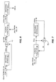
- Fig. 3 broadly summarizes such processing by depicting a method implemented in a wireless communication receiver of decoding modem bits from received sequence of symbols e g. a method implemented by the receiver 12 of Fig. 1 .
- the method comprises computing joint metrics (Block 100).
- each joint metric corresponds to a subset of the modem bits conveyed in the received sequence of symbols and indicates the likelihoods of those modem bits taking on certain bit values.
- Processing continues with generating side information for at least some of the modem bits represented in the joint metrics (Block 102).
- the side information for a given modem bit indicates that the given modem bit is more likely to have a particular bit value.
- processing continues with combining each joint metric with the side information for one or more modem bits represented in the joint metric, to obtain refined soft values for one or more remaining modem bits represented in the joint metric (Block 104).
- the method continues with decoding the refined soft values to recover corresponding modem bits from the received sequence of symbols, for those remaining modem bits that are coded, and for those remaining modem bits that are uncoded, producing an improved estimate (Block 106).
- the receiver circuit 32 is configured to generate the side information by demodulating a sequence of received symbols to produce a block of initial soft values, each representing the soft-value estimate for a bit conveyed in the received symbol sequence.
- These initial soft values are output from the equalizer circuit 34 values for further processing by the decoder circuit 36, which is configured to decode the block of initial soft values, to obtain a corresponding block of output soft values.
- the decoder circuit 36 subtracts the corresponding initial soft value from the corresponding output soft value.
- the decoder circuit 36 is configured to generate the side information by, in a first decoding iteration, generating a block of initial soft values corresponding to individual bits in a block of modem bits conveyed in the received sequence of symbols and decoding the block of initial soft values to obtain a corresponding block of output soft values. As such, to obtain the side information values for a given modem bit in the block, the decoder circuit 36 subtracts the corresponding initial soft value from the correponding output soft value.
- the equalizer circuit 34 is configured to select the subsets of modem bits for which joint metrics are computed by, for a given joint metric, selecting a first modem bit that is a coded bit in a first codeword, and selecting a second modem bit that is un-coded or belongs to a separate second codeword.
- the decoder circuit 36 is configured to generate the side information for the first modem bit in the given joint metric by decoding the first codeword according to any included error detection or correction coding, and subtracting the resulting output soft value from the corresponding input soft value used for said decoding of the first codeword.
- the equalizer circuit 34 is configured to select the subsets of modem bits for which joint metrics are computed by, for a given joint metric, selecting a first modem bit that is earlier in a codeword, and selecting a second modem bit that is later in the same codeword. Still further, as noted, in one or more embodiments, the equalizer circuit 34 comprises a joint simplified maximum a posteriori (JSMAP) equalizer. In such embodiments, the equalizer circuit 34 is configured to select the subsets of modem bits for which joint metrics are computed by selecting the subsets of modem bits as pairs of modem bits from consecutive trellis stages in the JSMAP equalizer.
- JSMAP joint simplified maximum a posteriori
- the equalizer circuit 34 is configured to select the subsets of modem bits for which joint metrics are computed as multiple modem bits from multiple, consecutive trellis stages in the JSMAP equalizer. Further, in at least one embodiment of the contemplated JSMAP implementation, the equalizer circuit 34 is configured to compute joint metrics for each given subset of modem bits, where the joint metrics are defined as a function of forward and reverse branch metrics and state metrics, from trellis stages of the JSMAP equalizer that are associated with the given subset of modem bits
- ISI inter-symbol interference
- the equalizer trellis captures all the relevant details of the system, where these details include the modulation constellation in use, for instance.
- the constellation represents the simultaneous streams. That is, a single 16QAM stream is represented by the sixteen modulation constellations points defined for that format, while a two stream 16QAM transmission is represented by a size-256 constellation.
- the different antenna signals contribute to the branch metric.
- the overall ISI is represented in the state space of the equalization trellis and in its state transitions.
- Such an equalizer can handle a very general system model.
- One aspect of the transmission scheme is the modulator mapping. For instance, in uncoded 16QAM, there is a mapping from groups of four bits to one of the sixteen defined modulation symbols. With coded modulation, e.g. trellis-coded modulation, the mapping description is more involved. For instance, in trellis-coded 16QAM with an imbedded rate three-fourths (3/4) code groups of three bits map into modulation symbol Regardless, it is clear what the modulation mapping is from the context of the particular transmission scheme.
- a given symbol represents a bits
- the trellis 50 comprises a number of successive trellis stages 52, with each stage 52 comprising a number of states 54.
- Each stage 52 corresponds to a symbol position/time of the received sequence of T symbols, and each state 54 within a given stage 52 is defined as a unique combination of the possible bit values that can be taken on by a symbol according to the defined modulation constellation
- a negative (positive) value of ⁇ t indicates that x is 1(0).
- Fig. 5 illustrates a configuration for the equalizer circuit 34, comprising an equalizer trellis 60 that includes a number of successive stages 62 with each stage comprising a number of states 64.
- a joint metric is first described for a pair of bits from two consecutive trellis stages 62. This derivation is then extended to multiple bits from multiple stages 62. Such workings may be further extended to a pair of bits from non-consecutive stages 62, and so on
- the contemplated joint metric is described for the degenerate case of bits from the same stage 62.
- the disclosure describes the interaction between the joint metric and a variant of the decoder circuit 36 that produces soft values for modern bits. Two scenarios are considered in this context one scenario where the bits in the joint metric belongs to separate codewords, and a scenario where the bits in the joint metric belong to the same codeword.
- I he triplet ( i , j , k ) denotes two consecutive connected branches, ( i , j ) from index t , and ( j , k ) from index t + 1.
- the set ⁇ '( x , y ) contains the triplets ( i , j , k ), where branch ( i , j ) has bit x set to 0 or 1, and branch ( j , k ) has bit y set to 0 or 1.
- the set of four values of L ' t ( x , y ) make up the information comprising the joint metric.
- the side information about bit y comes from the decoder circuit 36.
- the side information is expressed as an additive bias term ⁇ '( y ).
- the joint metric for the ( x , y ) bit pair includes representations corresponding to the tour possible combinations of bit values for the pair, namely, bit values (0,0), (0,1), (1,0), and (1,1,).
- the receiver circuit 32 uses side information about y to improve the decision about its neighboring bit x .
- one bit in the joint metric pair is a coded bit in a codeword, while the other bit is uncoded, or belongs to a separate codeword. Then the interaction between the decoder circuit 36 and the joint metric is limited to the side information output from the decoder circuit 36. That is, the decoder circuit 36 can operate in normal block fashion, defined by the codeword, and can process all its input, and produce its output in one block I hen the side information is sent to the joint metric for fusion and refined soft value generation, as just described.
- the bits in the joint metric belong to the same codeword. Then the interaction can take defferent forms. In one approach the interaction between the decoder circuit 36 and the joint metric remains in block fashion. In another approach, the interaction between the decoder circuit 36 and the joint metric occurs progressively within a single decoding operation, and the decoder circuit 36 includes particular modifications supporting this approach. In such contexts, in contrast to a generic, conventional decoder, which is normally concerned with producing soft (or hard) values about information bits, the decoder circuit 36 in such embodiments is configured to produce output soft values corresponding to the modern bits.
- the decoder circuit 36 is built based on a MAP decoder architecture. That is, the decoder can be a MAP decoder (using exponentials, etc.). However, other types of decoders, such as cheap SOVA and SMAP decoder architectures, could be modified along the same lines and used to practice variations of the above-described processing.
- bit y in the pair belongs to a codeword, while bit x either is uncoded or belongs to a separate codeword.
- This scenario is snited for certain error control schemes in speech coding which use separate coding of different bit classes, or leave certain bits uncoded.
- the side information is identified with ⁇ '( ⁇ ), as ⁇ is a bit in the codeword.
- the decoder circuit 36 can fuse ⁇ '( ⁇ ) as a bias in the corresponding joint metric, using (Eq. 11)-(Eq 14) That processing refines the soft value for the x bit in the joint metric.
- the equalizer 36 is not involved beyond its contribution of the joint metrics. The interaction is between the decoder circuit 36 and the joint metrics.
- a first decoding stage 40-1 receives initial soft values (for individual modem bits) from the equalizer circuit 34, and produces output soft values therefrom (abbreviated in the illustration as OSVs). for each bit, the corresponding initial soft value is subracted from the corresponding output soft value, via the summing circuit 70. The resulting difference serves as the side information for that bit.
- the subtraction performed here avoids the over-counting phenomenon, which has been identified in the study of turbo codes See e.g., C. Berrou, A. Glambiiere and P. Thitimajshima, "Near Shannon Limit Error-Correcting Coding and Decoding: Turbo-Codes", Proceedings IEEE ICC, 1993.
- the side information generated for the " y " bits, for a given plurality of ( x , y ) modem bit pairs, is provided to the fusion function 42 along with the corresponding joint metrics from the equalizer circuit 34.
- the fusion function 42 uses such information to produce refined soft values for the r bits represented in those joint metrics.
- One or more additional decoding stages 40 e.g. a decoding stage 40-2) in the decoder circuit 36 can then be used to decode the refined soft values.
- the decoder circuit 36 is used two or more times in block mode, in interaction with the joint metrics.
- the joint metrics are received at the decoder circuit 36, from the equalizer circuit 34.
- the equalizer is not involved any further beyond providing the joint metrics for richer decoding, along with providing the initial soft values.
- the decoder circuit 36 accepts a block of initial soft values from the equalizer circuit 34 (shown as ISVs), and produces a corresponding block of output soft values. These output soft values are used to produce a corresponding block of side information via the summing circuit 72 (based on subtraction, much as described for Fig. 6 ). In turn the side information is fed to the fusion function 42, which uses it to produce a block one new soft values, which are "refined” according to the use of JMs and SI, as taught herein. In the second iteration, the decoder circuit 36 accepts the block of new soft values, produces a block of new output soft values, and so on
- Yet another example considers side information for a common codeword, but based on a progressive approach. Again, one may consider the scenario where the joint metric bit pair belongs to the same codeword. According to this embodiment, output soft values corresponding to "early" modem bits in the codeword are used to modify the initial soft values for "later" modem bits in the same codeword. Unlike the two block approaches shown in Figs. 6 and 7 this approach modifies the inner workings of the decoder 36.
- Fig. 8 illustrates the above scenario with a convolutional code.
- the decoder circuit 36 has a decision depth d , which means that after d stages, the decoder circuit 36 produces output soft values for the modem bits corresponding to a first stage. After ( d + 1) stages the decoder produces OSV's for the modem bits of the second stage and so on.
- the fusion function 42 accepts the joint metrics from the equalizer 34.
- the original input soft values are fed to the decoder circuit 36.
- the output soft values begin to come out. Going back to a given original bit pair ( x , y ), suppose that y appears before x in the illustrated codeword 80 and that they are separated by no less than d stages. Then a refined soft value for x can be produced and substituted for the original (initial) soft value of x before the decoder circuit 36 needs to process it. To do so, an initial soft value is subtracted from the corresponding output soft value, to produce the side information, all fory y . The side information is fed to the fusion function 42 to produce the refined soft value for x . This in turn improves the overall decoder performance.
- the above ideas can be extended to non-neighboring stages. That is, it is possible to consider the joint metrics for modem bits from non-neighboring stages. For instance, consider two bits, x from index t , and y from index t + 2. Using the forward, backward state metrics, branch meb lCG ,is before, one can extend (Eq.
- the set ⁇ ( x,y ) contains the quadruplets ( i,j,k,l ), where branch ( i,j ) has bit x set to 0 or 1, and branch ( k , l ) has bit y set to 0 or 1.
- joint metric it is also possible to further extend the idea of the joint metric to multiple bits, including neighboring or non-neighboring stages, and single or multiple bits per stage This can be done by extending the formulation of the joint metric, as done in the two examples immediately above.
- one or more embodiments of the receiver circuit 32 are configured to use a window based approach.
- the forward recursion is carried as before.
- a backward recursion is carried from min( t + W,T ), where W is the window size.
- W is the window size.
- the starting state of the backward recursion is undetermined.
- the receiver circuit 32 is configured to set all the values N t+W ( k ) to the same constant, say 0, for example.
- the backward recursion is carried to index t , and the resulting values N t ( k ) are used to complete the bit metrics and soft value at index t.
- the receiver circuit 32 forms the core element of a super-receiver that uses enriched information fed forward from the equalizer circuit 34 to the decoder circuit 36.
- the enriched information is in joint metric form, and it expands upon and improves the SMAP equalizer structure.
- the contemplated receiver circuit 32 enhances performance over a receiver using SMAP at a small incremental cost in complexity.
- various apparatus and method embodiments are contemplated for implementation of the receiver circuit 32, and, as such, the present invention is not limited by the foregoing disclosure, or by the accompanying figures. Indeed, the present invention is limited only by the following appended claims, and their legal equivalents.
Landscapes
- Engineering & Computer Science (AREA)
- Power Engineering (AREA)
- Computer Networks & Wireless Communication (AREA)
- Signal Processing (AREA)
- Physics & Mathematics (AREA)
- Probability & Statistics with Applications (AREA)
- Error Detection And Correction (AREA)
- Digital Transmission Methods That Use Modulated Carrier Waves (AREA)
- Detection And Prevention Of Errors In Transmission (AREA)
- Circuits Of Receivers In General (AREA)
Claims (12)
- Procédé dans un récepteur de communication sans fil permettant de déterminer des bits de modem codés ou des bits de modem non codés, ou les deux, à partir d'une séquence reçue de symboles comprenant le fait :de calculer (100) des métriques conjointes, chaque métrique conjointe correspondant à un sous-ensemble comprenant deux bits ou plus parmi les bits de modem transférés dans la séquence reçue de symboles et indiquant les vraisemblances de ces bits de modem prenant certaines valeurs de bits ;et chaque métrique conjointe étant calculée en utilisant une fonction min des métriques d'état de récursion avant et arrière à partir des étages de treillis d'égalisation associés au sous-ensemble avec les métriques de branche associées ; oùun treillis (50) comprend un nombre d'étages de treillis successifs (52) avec chaque étage (52) comprenant un nombre d'états (54), chaque étage (52) correspond à une position de symbole/un instant de la séquence reçue de T symboles, et chaque état (54) dans un étage donné (52) est défini en tant que combinaison unique des valeurs de bits possibles qui peuvent être prises par un symbole selon la constellation de modulation définie ;une branche commençant à un état i à un indice t-1 et se terminant à un état j à un indice t est identifiée comme étant (i, j), la métrique de branche est désignée par δt (i, j) pour une récursion de métrique avant, la métrique d'état avant Mt(j) pour un état j à l'instant t est donnée par
 où Mt-1(i) est la métrique d'état avant pour un état i obtenue à partir d'une récursion avant MLSE à un indice t-1, sinon à un indice t=0, M0(0)=0, et M0(i)=∞, la métrique d'état arrière Nt(j) pour un état j à l'instant t est donnée par
 où N t+1(k) est la métrique d'état avant pour un état k obtenue à partir d'une récursion arrière MLSE à un indice t+1, sinon à un indice t=T, NT(0)=0, et NT(k)=∞, etla métrique conjointe pour la paire de bits (x, y) est

et oùle quadruplet (i, j, k, 1) désigne trois branches consécutives liées, une branche (i, j) à partir d'un indice t, une branche (j, k) à partir d'un indice t+1, et une branche (k, l) à partir d'un indice t+2, et l'ensemble Ω(x, y) contient les quadruplets (i, j, k, l), où une branche (i, j) a un bit x réglé à 0 ou 1, et une branche (k, 1) a un bit y réglé à 0 ou 1 ;le procédé comprenant en outre le fait :de générer (102) des informations supplémentaires µ(x), µ(y) pour la paire de bits (x, y) représentée dans les métriques conjointes,où les informations supplémentaires µ(x), µ(y) pour des bits de modem donnés (x, y) indiquent que les bits de modem donnés (x, y) sont les plus susceptibles d'avoir une valeur de bit particulière x = 1 (0), y = 1 (0) ;de combiner (104) chaque métrique conjointe avec les informations supplémentaires pour un ou plusieurs bit(s) de modem représenté(s) dans la métrique conjointe selon
 d'obtenir des valeurs logicielles affinées pour un ou plusieurs bit(s) de modem restant(s) représenté(s) dans la métrique conjointe selon
 de décoder (106), pour ces bits de modem restants qui sont codés, le cas échéant, les valeurs logicielles affinées pour récupérer des bits de modem correspondants à partir de la séquence reçue de symboles, etde produire (106), pour ces bits de modem restants qui sont non codés, le cas échéant, une estimation améliorée.
 - Procédé de la revendication 1, dans lequel la génération (102) des informations supplémentaires comprend le fait :de démoduler la séquence reçue de symboles pour produire un bloc de valeurs logicielles initiales, où chaque valeur logicielle initiale correspond à un bit parmi les bits de modem transférés dans la séquence reçue de symboles ;de décoder le bloc de valeurs logicielles initiales pour obtenir un bloc correspondant de valeurs logicielles de sortie ; etde soustraire la valeur logicielle initiale correspondante de la valeur logicielle de sortie correspondante pour obtenir les informations supplémentaires pour un bit de modem donné dans le bloc.
- Procédé de la revendication 1, dans lequel la génération (102) des informations supplémentaires comprend le fait :de générer, dans une première itération de décodage, un bloc de valeurs logicielles initiales correspondant à un bloc de bits de modem transférés dans la séquence reçue de symboles ;de décoder le bloc de valeurs logicielles initiales pour obtenir un bloc correspondant de valeurs logicielles de sortie ; etde soustraire la valeur logicielle initiale correspondante de la valeur logicielle de sortie correspondante pour obtenir les informations supplémentaires pour un bit de modem donné dans le bloc.
- Procédé de la revendication 1, dans lequel le calcul (100) des métriques conjointes comporte le fait de sélectionner les sous-ensembles de bits de modem pour lesquels des métriques conjointes sont calculées, pour une métrique conjointe donnée, en sélectionnant un premier bit de modem qui est un bit codé dans un premier mot de code et en sélectionnant un deuxième bit de modem qui est non codé ou qui appartient à un deuxième mot de code différent.
- Procédé de la revendication 4, dans lequel la génération (102) des informations supplémentaires pour le premier bit de modem de la métrique conjointe donnée comprend le fait de décoder le premier mot de code selon un codage quelconque de détection ou de correction d'erreur inclus et de soustraire la valeur logicielle de sortie résultante de la valeur logicielle d'entrée correspondante utilisée pour ledit décodage du premier mot de code.
- Procédé de la revendication 4, dans lequel le calcul (100) des métriques conjointes comporte le fait de sélectionner les sous-ensembles de bits de modem pour lesquels des métriques conjointes sont calculées, pour une métrique conjointe donnée, en sélectionnant un premier bit de modem qui est un bit antérieur dans un mot de code, et en sélectionnant un deuxième bit de modem qui est un bit ultérieur dans le même mot de code.
- Circuit récepteur configuré pour déterminer des bits de modem codés ou des bits de modem non codés, ou les deux, à partir d'une séquence reçue de symboles et comprenant :un circuit égaliseur (34) configuré pour calculer des métriques conjointes, chaque métrique conjointe correspondant à un sous-ensemble de deux bits ou plus parmi les bits de modem transférés dans la séquence reçue de symboles et indiquant la vraisemblance de ces bits de modem prenant certaines valeurs de bits ; etchaque métrique conjointe étant calculée en utilisant une fonction min des métriques d'état de récursion avant et arrière à partir des étages de treillis d'égalisation associés au sous-ensemble avec les métriques de branche associées ; oùun treillis (50) comprend un nombre d'étages de treillis successifs (52) avec chaque étage (52) comprenant un nombre d'états (54), chaque étage (52) correspond à une position de symbole/un instant de la séquence reçue de T symboles, et chaque état (54) dans un étage donné (52) est défini en tant que combinaison unique des valeurs de bits possibles qui peuvent être prises par un symbole selon la constellation de modulation définie ;une branche commençant à un état i à un indice t-1 et se terminant à un état j à un indice t est identifiée comme étant (i, j), la métrique de branche est désignée par δt(i, j) pour une récursion de métrique avant, la métrique d'état avant Mt(j) pour un état j à l'instant t est donnée par
 où Mt-1(i) est la métrique d'état avant pour un état i obtenue à partir d'une récursion avant MLSE à un indice t-1, sinon à un indice t=0, M0(0)=0, et M0(i)=∞, la métrique d'état arrière Nt(j) pour un état j à l'instant t est donnée par
 où N t+1(k) est la métrique d'état avant pour un état k obtenue à partir d'une récursion arrière MLSE à un indice t+1, sinon à un indice t=T, NT(0)=0, et NT(k)=∞, etla métrique conjointe pour la paire de bits (x, y) est

et oùle quadruplet (i, j, k, 1) désigne trois branches consécutives liées, une branche (i, j) à partir d'un indice t, une branche (j, k) à partir d'un indice t+1, et une branche (k, l) à partir d'un indice t+2, et l'ensemble Ω(x, y) contient les quadruplets (i, j, k, 1), où une branche (i, j) a un bit x réglé à 0 ou 1, et une branche (k, 1) a un bit y réglé à 0 ou 1 ;le circuit récepteur comprenant en outre un circuit décodeur (36) configuré :pour générer (102) des informations supplémentaires µ(x), µ(y) pour la paire de bit (x, y) représentée dans les métriques conjointes, où les informations supplémentaires µ(x), µ(y) pour des bits de modem donnés (x, y) indiquent que les bits de modem donnés (x, y) sont les plus susceptibles d'avoir une valeur de bit particulière x = 1 (0), y = 1 (0) ;pour combiner (104) chaque métrique conjointe avec les informations supplémentaires pour un ou plusieurs bit(s) de modem représenté(s) dans la métrique conjointe selon
 pour obtenir des valeurs logicielles affinées pour un ou plusieurs bit(s) de modem restant(s) représenté(s) dans la métrique conjointe selon
 pour décoder, pour ces bits de modem restants qui sont codés, le cas échéant, les valeurs logicielles affinées pour récupérer des bits de modem correspondants à partir de la séquence reçue de symboles ; etpour produire, pour ces bits de modem restants qui sont non codés, le cas échéant, une estimation améliorée.
 - Circuit récepteur de la revendication 7, dans lequel le circuit décodeur (36) est configuré pour générer les informations supplémentaires :en démodulant une séquence de symboles reçus pour produire un bloc de valeurs logicielles initiales, où chaque valeur logicielle initiale correspond à un bit parmi les bits de modem transférés dans la séquence reçue de symboles ;en décodant le bloc de valeurs logicielles initiales pour obtenir un bloc correspondant de valeurs logicielles de sortie ; eten soustrayant la valeur logicielle initiale correspondante de la valeur logicielle de sortie correspondante pour obtenir les informations supplémentaires pour un bit donné parmi les bits de modem dans le bloc.
- Circuit récepteur de la revendication 7, dans lequel le circuit décodeur (36) est configuré pour générer les informations supplémentaires :en générant, dans une première itération de décodage, un bloc de valeurs logicielles initiales correspondant à un bloc de bits de modem transférés dans la séquence reçue de symboles ;en décodant le bloc de valeurs logicielles initiales pour obtenir un bloc correspondant de valeurs logicielles de sortie ; eten soustrayant la valeur logicielle initiale correspondante de la valeur logicielle de sortie correspondante pour obtenir les informations supplémentaires pour un bit de modem donné dans le bloc.
- Circuit récepteur de la revendication 7, dans lequel le circuit égaliseur (34) est configuré pour sélectionner les sous-ensembles de bits de modem pour lesquels des métriques conjointes sont calculées, pour une métrique conjointe donnée, en sélectionnant un premier bit de modem qui est un bit codé dans un premier mot de code, et en sélectionnant un deuxième bit de modem qui est non codé ou appartient à un deuxième mot de code différent.
- Circuit récepteur de la revendication 10, dans lequel le circuit décodeur (36) est configuré pour générer les informations supplémentaires pour le premier bit de modem dans la métrique conjointe donnée en décodant le premier mot de code selon un codage quelconque de détection ou de correction d'erreur inclus, et en soustrayant la valeur logicielle de sortie résultante de la valeur logicielle d'entrée correspondante pour ledit décodage du premier mot de code.
- Circuit récepteur de la revendication 7, dans lequel le circuit égaliseur (34) est configuré pour sélectionner les sous-ensembles de bits de modem pour lesquels des métriques conjointes sont calculées, pour une métrique conjointe donnée, en sélectionnant un premier bit de modem qui est un bit antérieur dans un mot de code, et en sélectionnant un deuxième bit de modem qui est un bit ultérieur dans le même mot de code.
Applications Claiming Priority (2)
| Application Number | Priority Date | Filing Date | Title |
|---|---|---|---|
| US12/542,335 US8331495B2 (en) | 2009-08-17 | 2009-08-17 | Method and apparatus for an improved wireless communication receiver |
| PCT/IB2010/053692 WO2011021143A2 (fr) | 2009-08-17 | 2010-08-16 | Procédé et appareil pour un récepteur de communication sans fil amélioré |
Publications (2)
| Publication Number | Publication Date |
|---|---|
| EP2467983A2 EP2467983A2 (fr) | 2012-06-27 |
| EP2467983B1 true EP2467983B1 (fr) | 2014-04-30 |
Family
ID=43500600
Family Applications (1)
| Application Number | Title | Priority Date | Filing Date |
|---|---|---|---|
| EP10752934.9A Not-in-force EP2467983B1 (fr) | 2009-08-17 | 2010-08-16 | Procédé et appareil pour un récepteur de communication sans fil amélioré |
Country Status (5)
| Country | Link |
|---|---|
| US (1) | US8331495B2 (fr) |
| EP (1) | EP2467983B1 (fr) |
| CL (1) | CL2010000878A1 (fr) |
| TW (1) | TWI504168B (fr) |
| WO (1) | WO2011021143A2 (fr) |
Citations (1)
| Publication number | Priority date | Publication date | Assignee | Title |
|---|---|---|---|---|
| WO2010073096A1 (fr) * | 2008-12-23 | 2010-07-01 | Telefonaktiebolaget L M Ericsson (Publ) | Récepteur à correction aval et procédé destinés à réduire les interférences entre symboles en utilisant un couplage de bits ou de symboles |
Family Cites Families (10)
| Publication number | Priority date | Publication date | Assignee | Title |
|---|---|---|---|---|
| US5151919A (en) * | 1990-12-17 | 1992-09-29 | Ericsson-Ge Mobile Communications Holding Inc. | Cdma subtractive demodulation |
| US6658071B1 (en) * | 2000-02-14 | 2003-12-02 | Ericsson Inc. | Delayed decision feedback log-map equalizer |
| US6697441B1 (en) * | 2000-06-06 | 2004-02-24 | Ericsson Inc. | Baseband processors and methods and systems for decoding a received signal having a transmitter or channel induced coupling between bits |
| US6798852B2 (en) | 2000-06-06 | 2004-09-28 | Ericsson Inc. | Methods and systems for extracting a joint probability from a map decision device and processing a signal using the joint probability information |
| US7042938B2 (en) * | 2001-08-13 | 2006-05-09 | Nokia Corporation | Soft bit computation for a reduced state equalizer |
| US20030115061A1 (en) | 2001-09-11 | 2003-06-19 | Broadcom Corporation | MPSK equalizer |
| JP4490265B2 (ja) | 2002-07-24 | 2010-06-23 | ビーエイイー・システムズ・インフォメーション・アンド・エレクトロニック・システムズ・インテグレイション・インコーポレーテッド | 同一チャネル干渉受信機 |
| US7813453B2 (en) * | 2004-01-21 | 2010-10-12 | Qualcomm Incorporated | Data detection for a hierarchical coded data transmission |
| US8391410B2 (en) * | 2004-07-29 | 2013-03-05 | Qualcomm Incorporated | Methods and apparatus for configuring a pilot symbol in a wireless communication system |
| US8031793B2 (en) * | 2005-01-19 | 2011-10-04 | Dumitru Mihai Ionescu | Apparatus using concatenations of signal-space codes for jointly encoding across multiple transmit antennas, and employing coordinate interleaving |
-
2009
- 2009-08-17 US US12/542,335 patent/US8331495B2/en not_active Expired - Fee Related
-
2010
- 2010-08-16 TW TW099127333A patent/TWI504168B/zh not_active IP Right Cessation
- 2010-08-16 EP EP10752934.9A patent/EP2467983B1/fr not_active Not-in-force
- 2010-08-16 WO PCT/IB2010/053692 patent/WO2011021143A2/fr not_active Ceased
- 2010-08-17 CL CL2010000878A patent/CL2010000878A1/es unknown
Patent Citations (1)
| Publication number | Priority date | Publication date | Assignee | Title |
|---|---|---|---|---|
| WO2010073096A1 (fr) * | 2008-12-23 | 2010-07-01 | Telefonaktiebolaget L M Ericsson (Publ) | Récepteur à correction aval et procédé destinés à réduire les interférences entre symboles en utilisant un couplage de bits ou de symboles |
Non-Patent Citations (1)
| Title |
|---|
| L. BAHL; J. COCKE; F. JELINEK; J. RAVIV: "Optimal decoding of linear codes for minimizing symbol error rate", IEEE TRANS. INFORM. THY., March 1974 (1974-03-01), pages 284 - 287, XP000647243, DOI: doi:10.1109/TIT.1974.1055186 * |
Also Published As
| Publication number | Publication date |
|---|---|
| US20110038402A1 (en) | 2011-02-17 |
| WO2011021143A3 (fr) | 2011-04-28 |
| US8331495B2 (en) | 2012-12-11 |
| EP2467983A2 (fr) | 2012-06-27 |
| TW201112652A (en) | 2011-04-01 |
| TWI504168B (zh) | 2015-10-11 |
| WO2011021143A2 (fr) | 2011-02-24 |
| CL2010000878A1 (es) | 2011-07-15 |
Similar Documents
| Publication | Publication Date | Title |
|---|---|---|
| US6658071B1 (en) | Delayed decision feedback log-map equalizer | |
| US6996194B2 (en) | Method and arrangement for iteratively improving a channel estimate | |
| EP1236282A1 (fr) | Algorithme d'estimation de symbole a recherche limitee | |
| CN102265571B (zh) | 用于通过使用比特或符号之间的耦合来降低符号间干扰的前馈接收器和方法 | |
| US8385450B2 (en) | Metrics calculations utilizing pre-stored values | |
| JP2003533945A (ja) | 伝送チャネルの係数の再推定と結合された、受信シンボルを繰り返し検出し、かつ復号化する方法及びシステム | |
| EP2353242B1 (fr) | Procédé et appareil d'estimation non stricte de bits de parité et systématiques | |
| CN102625983B (zh) | 涡轮解码器中编码比特的有效软值生成方法及装置 | |
| US8340204B2 (en) | Soft decision enhancement | |
| AU1978000A (en) | Method and system for fast maximum a posteriori decoding | |
| EP2467983B1 (fr) | Procédé et appareil pour un récepteur de communication sans fil amélioré | |
| CN1938955A (zh) | 局部擦除极大后验译码器 | |
| Anastasopoulos et al. | Soft-decisions per-survivor processing for mobile fading channels | |
| Sun et al. | Serially concatenated continuous phase modulation with reduced iterative demodulation and detection | |
| Myburgh et al. | A primer on equalization, decoding and non-iterative joint equalization and decoding | |
| Baek et al. | An Efficient Turbo Equalization for Faster than Nyquist Signal | |
| Paun et al. | LISS algorithm with modified length bias term in turbo equalization | |
| Wu et al. | A robust detection algorithm for the multi-path channel |
Legal Events
| Date | Code | Title | Description |
|---|---|---|---|
| PUAI | Public reference made under article 153(3) epc to a published international application that has entered the european phase |
Free format text: ORIGINAL CODE: 0009012 |
|
| 17P | Request for examination filed |
Effective date: 20120309 |
|
| AK | Designated contracting states |
Kind code of ref document: A2 Designated state(s): AL AT BE BG CH CY CZ DE DK EE ES FI FR GB GR HR HU IE IS IT LI LT LU LV MC MK MT NL NO PL PT RO SE SI SK SM TR |
|
| DAX | Request for extension of the european patent (deleted) | ||
| 17Q | First examination report despatched |
Effective date: 20121218 |
|
| GRAP | Despatch of communication of intention to grant a patent |
Free format text: ORIGINAL CODE: EPIDOSNIGR1 |
|
| INTG | Intention to grant announced |
Effective date: 20131209 |
|
| RAP1 | Party data changed (applicant data changed or rights of an application transferred) |
Owner name: TELEFONAKTIEBOLAGET L M ERICSSON (PUBL) |
|
| GRAS | Grant fee paid |
Free format text: ORIGINAL CODE: EPIDOSNIGR3 |
|
| GRAA | (expected) grant |
Free format text: ORIGINAL CODE: 0009210 |
|
| AK | Designated contracting states |
Kind code of ref document: B1 Designated state(s): AL AT BE BG CH CY CZ DE DK EE ES FI FR GB GR HR HU IE IS IT LI LT LU LV MC MK MT NL NO PL PT RO SE SI SK SM TR |
|
| REG | Reference to a national code |
Ref country code: CH Ref legal event code: EP Ref country code: GB Ref legal event code: FG4D |
|
| REG | Reference to a national code |
Ref country code: AT Ref legal event code: REF Ref document number: 665747 Country of ref document: AT Kind code of ref document: T Effective date: 20140515 |
|
| REG | Reference to a national code |
Ref country code: IE Ref legal event code: FG4D |
|
| REG | Reference to a national code |
Ref country code: DE Ref legal event code: R096 Ref document number: 602010015634 Country of ref document: DE Effective date: 20140612 |
|
| REG | Reference to a national code |
Ref country code: AT Ref legal event code: MK05 Ref document number: 665747 Country of ref document: AT Kind code of ref document: T Effective date: 20140430 |
|
| REG | Reference to a national code |
Ref country code: LT Ref legal event code: MG4D |
|
| REG | Reference to a national code |
Ref country code: NL Ref legal event code: VDEP Effective date: 20140430 |
|
| PG25 | Lapsed in a contracting state [announced via postgrant information from national office to epo] |
Ref country code: FI Free format text: LAPSE BECAUSE OF FAILURE TO SUBMIT A TRANSLATION OF THE DESCRIPTION OR TO PAY THE FEE WITHIN THE PRESCRIBED TIME-LIMIT Effective date: 20140430 Ref country code: LT Free format text: LAPSE BECAUSE OF FAILURE TO SUBMIT A TRANSLATION OF THE DESCRIPTION OR TO PAY THE FEE WITHIN THE PRESCRIBED TIME-LIMIT Effective date: 20140430 Ref country code: NL Free format text: LAPSE BECAUSE OF FAILURE TO SUBMIT A TRANSLATION OF THE DESCRIPTION OR TO PAY THE FEE WITHIN THE PRESCRIBED TIME-LIMIT Effective date: 20140430 Ref country code: CY Free format text: LAPSE BECAUSE OF FAILURE TO SUBMIT A TRANSLATION OF THE DESCRIPTION OR TO PAY THE FEE WITHIN THE PRESCRIBED TIME-LIMIT Effective date: 20140430 Ref country code: NO Free format text: LAPSE BECAUSE OF FAILURE TO SUBMIT A TRANSLATION OF THE DESCRIPTION OR TO PAY THE FEE WITHIN THE PRESCRIBED TIME-LIMIT Effective date: 20140730 Ref country code: IS Free format text: LAPSE BECAUSE OF FAILURE TO SUBMIT A TRANSLATION OF THE DESCRIPTION OR TO PAY THE FEE WITHIN THE PRESCRIBED TIME-LIMIT Effective date: 20140830 Ref country code: BG Free format text: LAPSE BECAUSE OF FAILURE TO SUBMIT A TRANSLATION OF THE DESCRIPTION OR TO PAY THE FEE WITHIN THE PRESCRIBED TIME-LIMIT Effective date: 20140730 Ref country code: GR Free format text: LAPSE BECAUSE OF FAILURE TO SUBMIT A TRANSLATION OF THE DESCRIPTION OR TO PAY THE FEE WITHIN THE PRESCRIBED TIME-LIMIT Effective date: 20140731 |
|
| PG25 | Lapsed in a contracting state [announced via postgrant information from national office to epo] |
Ref country code: ES Free format text: LAPSE BECAUSE OF FAILURE TO SUBMIT A TRANSLATION OF THE DESCRIPTION OR TO PAY THE FEE WITHIN THE PRESCRIBED TIME-LIMIT Effective date: 20140430 Ref country code: LV Free format text: LAPSE BECAUSE OF FAILURE TO SUBMIT A TRANSLATION OF THE DESCRIPTION OR TO PAY THE FEE WITHIN THE PRESCRIBED TIME-LIMIT Effective date: 20140430 Ref country code: AT Free format text: LAPSE BECAUSE OF FAILURE TO SUBMIT A TRANSLATION OF THE DESCRIPTION OR TO PAY THE FEE WITHIN THE PRESCRIBED TIME-LIMIT Effective date: 20140430 Ref country code: HR Free format text: LAPSE BECAUSE OF FAILURE TO SUBMIT A TRANSLATION OF THE DESCRIPTION OR TO PAY THE FEE WITHIN THE PRESCRIBED TIME-LIMIT Effective date: 20140430 Ref country code: SE Free format text: LAPSE BECAUSE OF FAILURE TO SUBMIT A TRANSLATION OF THE DESCRIPTION OR TO PAY THE FEE WITHIN THE PRESCRIBED TIME-LIMIT Effective date: 20140430 Ref country code: PL Free format text: LAPSE BECAUSE OF FAILURE TO SUBMIT A TRANSLATION OF THE DESCRIPTION OR TO PAY THE FEE WITHIN THE PRESCRIBED TIME-LIMIT Effective date: 20140430 |
|
| PG25 | Lapsed in a contracting state [announced via postgrant information from national office to epo] |
Ref country code: PT Free format text: LAPSE BECAUSE OF FAILURE TO SUBMIT A TRANSLATION OF THE DESCRIPTION OR TO PAY THE FEE WITHIN THE PRESCRIBED TIME-LIMIT Effective date: 20140901 |
|
| PG25 | Lapsed in a contracting state [announced via postgrant information from national office to epo] |
Ref country code: DK Free format text: LAPSE BECAUSE OF FAILURE TO SUBMIT A TRANSLATION OF THE DESCRIPTION OR TO PAY THE FEE WITHIN THE PRESCRIBED TIME-LIMIT Effective date: 20140430 Ref country code: EE Free format text: LAPSE BECAUSE OF FAILURE TO SUBMIT A TRANSLATION OF THE DESCRIPTION OR TO PAY THE FEE WITHIN THE PRESCRIBED TIME-LIMIT Effective date: 20140430 Ref country code: SK Free format text: LAPSE BECAUSE OF FAILURE TO SUBMIT A TRANSLATION OF THE DESCRIPTION OR TO PAY THE FEE WITHIN THE PRESCRIBED TIME-LIMIT Effective date: 20140430 Ref country code: BE Free format text: LAPSE BECAUSE OF FAILURE TO SUBMIT A TRANSLATION OF THE DESCRIPTION OR TO PAY THE FEE WITHIN THE PRESCRIBED TIME-LIMIT Effective date: 20140430 Ref country code: RO Free format text: LAPSE BECAUSE OF FAILURE TO SUBMIT A TRANSLATION OF THE DESCRIPTION OR TO PAY THE FEE WITHIN THE PRESCRIBED TIME-LIMIT Effective date: 20140430 Ref country code: CZ Free format text: LAPSE BECAUSE OF FAILURE TO SUBMIT A TRANSLATION OF THE DESCRIPTION OR TO PAY THE FEE WITHIN THE PRESCRIBED TIME-LIMIT Effective date: 20140430 |
|
| REG | Reference to a national code |
Ref country code: DE Ref legal event code: R097 Ref document number: 602010015634 Country of ref document: DE |
|
| PLBE | No opposition filed within time limit |
Free format text: ORIGINAL CODE: 0009261 |
|
| STAA | Information on the status of an ep patent application or granted ep patent |
Free format text: STATUS: NO OPPOSITION FILED WITHIN TIME LIMIT |
|
| PG25 | Lapsed in a contracting state [announced via postgrant information from national office to epo] |
Ref country code: MC Free format text: LAPSE BECAUSE OF FAILURE TO SUBMIT A TRANSLATION OF THE DESCRIPTION OR TO PAY THE FEE WITHIN THE PRESCRIBED TIME-LIMIT Effective date: 20140430 Ref country code: LU Free format text: LAPSE BECAUSE OF FAILURE TO SUBMIT A TRANSLATION OF THE DESCRIPTION OR TO PAY THE FEE WITHIN THE PRESCRIBED TIME-LIMIT Effective date: 20140816 Ref country code: IT Free format text: LAPSE BECAUSE OF FAILURE TO SUBMIT A TRANSLATION OF THE DESCRIPTION OR TO PAY THE FEE WITHIN THE PRESCRIBED TIME-LIMIT Effective date: 20140430 |
|
| REG | Reference to a national code |
Ref country code: CH Ref legal event code: PL |
|
| 26N | No opposition filed |
Effective date: 20150202 |
|
| GBPC | Gb: european patent ceased through non-payment of renewal fee |
Effective date: 20140816 |
|
| PG25 | Lapsed in a contracting state [announced via postgrant information from national office to epo] |
Ref country code: CH Free format text: LAPSE BECAUSE OF NON-PAYMENT OF DUE FEES Effective date: 20140831 Ref country code: LI Free format text: LAPSE BECAUSE OF NON-PAYMENT OF DUE FEES Effective date: 20140831 |
|
| REG | Reference to a national code |
Ref country code: DE Ref legal event code: R097 Ref document number: 602010015634 Country of ref document: DE Effective date: 20150202 |
|
| REG | Reference to a national code |
Ref country code: IE Ref legal event code: MM4A |
|
| REG | Reference to a national code |
Ref country code: FR Ref legal event code: ST Effective date: 20150430 |
|
| PG25 | Lapsed in a contracting state [announced via postgrant information from national office to epo] |
Ref country code: GB Free format text: LAPSE BECAUSE OF NON-PAYMENT OF DUE FEES Effective date: 20140816 Ref country code: SI Free format text: LAPSE BECAUSE OF FAILURE TO SUBMIT A TRANSLATION OF THE DESCRIPTION OR TO PAY THE FEE WITHIN THE PRESCRIBED TIME-LIMIT Effective date: 20140430 |
|
| PG25 | Lapsed in a contracting state [announced via postgrant information from national office to epo] |
Ref country code: IE Free format text: LAPSE BECAUSE OF NON-PAYMENT OF DUE FEES Effective date: 20140816 Ref country code: FR Free format text: LAPSE BECAUSE OF NON-PAYMENT OF DUE FEES Effective date: 20140901 |
|
| PG25 | Lapsed in a contracting state [announced via postgrant information from national office to epo] |
Ref country code: SM Free format text: LAPSE BECAUSE OF FAILURE TO SUBMIT A TRANSLATION OF THE DESCRIPTION OR TO PAY THE FEE WITHIN THE PRESCRIBED TIME-LIMIT Effective date: 20140430 |
|
| PG25 | Lapsed in a contracting state [announced via postgrant information from national office to epo] |
Ref country code: MT Free format text: LAPSE BECAUSE OF FAILURE TO SUBMIT A TRANSLATION OF THE DESCRIPTION OR TO PAY THE FEE WITHIN THE PRESCRIBED TIME-LIMIT Effective date: 20140430 |
|
| PG25 | Lapsed in a contracting state [announced via postgrant information from national office to epo] |
Ref country code: TR Free format text: LAPSE BECAUSE OF FAILURE TO SUBMIT A TRANSLATION OF THE DESCRIPTION OR TO PAY THE FEE WITHIN THE PRESCRIBED TIME-LIMIT Effective date: 20140430 Ref country code: HU Free format text: LAPSE BECAUSE OF FAILURE TO SUBMIT A TRANSLATION OF THE DESCRIPTION OR TO PAY THE FEE WITHIN THE PRESCRIBED TIME-LIMIT; INVALID AB INITIO Effective date: 20100816 |
|
| PG25 | Lapsed in a contracting state [announced via postgrant information from national office to epo] |
Ref country code: MK Free format text: LAPSE BECAUSE OF FAILURE TO SUBMIT A TRANSLATION OF THE DESCRIPTION OR TO PAY THE FEE WITHIN THE PRESCRIBED TIME-LIMIT Effective date: 20140430 |
|
| PG25 | Lapsed in a contracting state [announced via postgrant information from national office to epo] |
Ref country code: AL Free format text: LAPSE BECAUSE OF FAILURE TO SUBMIT A TRANSLATION OF THE DESCRIPTION OR TO PAY THE FEE WITHIN THE PRESCRIBED TIME-LIMIT Effective date: 20140430 |
|
| PGFP | Annual fee paid to national office [announced via postgrant information from national office to epo] |
Ref country code: DE Payment date: 20220629 Year of fee payment: 13 |
|
| REG | Reference to a national code |
Ref country code: DE Ref legal event code: R119 Ref document number: 602010015634 Country of ref document: DE |
|
| PG25 | Lapsed in a contracting state [announced via postgrant information from national office to epo] |
Ref country code: DE Free format text: LAPSE BECAUSE OF NON-PAYMENT OF DUE FEES Effective date: 20240301 |