EP2467704B1 - Heatable glazing inspection - Google Patents
Heatable glazing inspection Download PDFInfo
- Publication number
- EP2467704B1 EP2467704B1 EP20100744937 EP10744937A EP2467704B1 EP 2467704 B1 EP2467704 B1 EP 2467704B1 EP 20100744937 EP20100744937 EP 20100744937 EP 10744937 A EP10744937 A EP 10744937A EP 2467704 B1 EP2467704 B1 EP 2467704B1
- Authority
- EP
- European Patent Office
- Prior art keywords
- shadowgraph image
- glazing
- heater
- heatable
- shadowgraph
- Prior art date
- Legal status (The legal status is an assumption and is not a legal conclusion. Google has not performed a legal analysis and makes no representation as to the accuracy of the status listed.)
- Active
Links
- 238000007689 inspection Methods 0.000 title description 7
- 238000000034 method Methods 0.000 claims description 40
- 238000003384 imaging method Methods 0.000 claims description 16
- 238000004458 analytical method Methods 0.000 description 12
- 239000011521 glass Substances 0.000 description 11
- 238000010438 heat treatment Methods 0.000 description 8
- 238000005259 measurement Methods 0.000 description 7
- 239000004020 conductor Substances 0.000 description 6
- 238000010276 construction Methods 0.000 description 6
- 230000000694 effects Effects 0.000 description 5
- 238000005286 illumination Methods 0.000 description 4
- 239000000463 material Substances 0.000 description 4
- 230000003287 optical effect Effects 0.000 description 4
- 238000000926 separation method Methods 0.000 description 4
- 238000003491 array Methods 0.000 description 2
- 238000004891 communication Methods 0.000 description 2
- 230000005494 condensation Effects 0.000 description 2
- 238000009833 condensation Methods 0.000 description 2
- 239000011229 interlayer Substances 0.000 description 2
- 239000004033 plastic Substances 0.000 description 2
- 229920003023 plastic Polymers 0.000 description 2
- 238000013459 approach Methods 0.000 description 1
- 238000007664 blowing Methods 0.000 description 1
- 238000012937 correction Methods 0.000 description 1
- 230000007547 defect Effects 0.000 description 1
- 230000002950 deficient Effects 0.000 description 1
- 238000001514 detection method Methods 0.000 description 1
- 238000010586 diagram Methods 0.000 description 1
- 239000000428 dust Substances 0.000 description 1
- 238000010891 electric arc Methods 0.000 description 1
- 230000005611 electricity Effects 0.000 description 1
- 239000005329 float glass Substances 0.000 description 1
- 239000010410 layer Substances 0.000 description 1
- 238000004519 manufacturing process Methods 0.000 description 1
- 239000004417 polycarbonate Substances 0.000 description 1
- 229920000515 polycarbonate Polymers 0.000 description 1
- 238000001931 thermography Methods 0.000 description 1
- 239000011800 void material Substances 0.000 description 1
Images


Classifications
-
- H—ELECTRICITY
- H05—ELECTRIC TECHNIQUES NOT OTHERWISE PROVIDED FOR
- H05B—ELECTRIC HEATING; ELECTRIC LIGHT SOURCES NOT OTHERWISE PROVIDED FOR; CIRCUIT ARRANGEMENTS FOR ELECTRIC LIGHT SOURCES, IN GENERAL
- H05B3/00—Ohmic-resistance heating
- H05B3/84—Heating arrangements specially adapted for transparent or reflecting areas, e.g. for demisting or de-icing windows, mirrors or vehicle windshields
-
- G—PHYSICS
- G01—MEASURING; TESTING
- G01N—INVESTIGATING OR ANALYSING MATERIALS BY DETERMINING THEIR CHEMICAL OR PHYSICAL PROPERTIES
- G01N21/00—Investigating or analysing materials by the use of optical means, i.e. using sub-millimetre waves, infrared, visible or ultraviolet light
- G01N21/84—Systems specially adapted for particular applications
- G01N21/88—Investigating the presence of flaws or contamination
- G01N21/95—Investigating the presence of flaws or contamination characterised by the material or shape of the object to be examined
- G01N21/958—Inspecting transparent materials or objects, e.g. windscreens
-
- H—ELECTRICITY
- H05—ELECTRIC TECHNIQUES NOT OTHERWISE PROVIDED FOR
- H05B—ELECTRIC HEATING; ELECTRIC LIGHT SOURCES NOT OTHERWISE PROVIDED FOR; CIRCUIT ARRANGEMENTS FOR ELECTRIC LIGHT SOURCES, IN GENERAL
- H05B2203/00—Aspects relating to Ohmic resistive heating covered by group H05B3/00
- H05B2203/017—Manufacturing methods or apparatus for heaters
Definitions
- the present invention relates to the optical inspection of vehicle glazings, in particular to the optical inspection of a heatable laminated glazing comprising an array of heater wires laminated between a pair of glass sheets.
- windscreens have a laminated construction for safety reasons.
- a standard feature of a vehicle is the inclusion of a fan assembly designed to blow air onto the inner surface of the vehicle windscreen to demist the inner surface, thereby removing condensation from the inner surface thereof and improving the driver's visibility through the glazing.
- the fan may be used to remove the ice from the windscreen by blowing warm air onto the windscreen, thereby de-icing the windscreen.
- some vehicles may also have a heatable windscreen, wherein laminated between the plies of the windscreen is a heater array that is connectable to the car battery.
- the heater array comprises a plurality of spaced electrical conductors, each in the form of fine wires, often known as heater wires.
- an electrical current passes through the heater array causing the heater wires to heat up. This provides localised heating of the windscreen in the vicinity of the heater array that is sufficient to remove ice from the windscreen.
- Such electrically heatable windows may be installed in cars, boats, aircraft and buildings. A construction of a laminated transparent panel incorporating heater wires is described in GB 972,453 . Often in the art such heatable windows are referred to as heated windows.
- the heater array is able to uniformly remove ice and/or condensation from the glazing surfaces.
- the vehicle manufacturer usually specifies the requirements of the heater array, such as the electrically resistance of the wires, the material characteristics of the wires, the configuration of the wires (whether straight or not), the thickness of each wire, the length of each wire, the number of active heater wires and their separation.
- the heater wires are uniformly spaced from the top of the windscreen to bottom i.e. they should be parallel, wherein the top of the windscreen refers to that edge nearest the roof of the vehicle in the installed position.
- JP6249905A a method and apparatus for inspecting blur-protected glass is disclosed.
- the apparatus comprises a detection part that brings a roller into contact with the glass being measured.
- the roller scans the glass a slice at a time.
- a photoelectric sensor detects the number of electricity feeding filaments.
- Such a method of inspection is slow because the glazing is scanned a line at a time, thereby taking a long time to make measurements.
- US2003/0151739A1 discloses an apparatus and method for quantitatively measuring ripple and distortion levels in a transparent sheet material.
- the present invention provides from a first aspect a method of inspecting a heatable glazing, the heatable glazing comprising a heater array comprising a heater wire, the method comprising the steps
- step (ii) may precede step (i).
- a method in accordance with the first aspect of the present invention allows the heater array in a heatable glazing to be rapidly inspected.
- the active shadowgraph image is projected onto a screen, and the imaging sensor captures the active shadowgraph image that is projected onto the screen.
- the active shadowgraph image is not projected onto a screen, but is instead projected onto a plane in space, and the imaging sensor focuses onto the plane in space to capture the active shadowgraph image.
- the method comprises the step of illuminating the glazing when insufficient electrical current is passing through the heater array such that the heater wire is not observable in the shadowgraph image, thereby producing a reference shadowgraph image of the heatable glazing, capturing the reference shadowgraph image, and comparing the active shadowgraph image of the heatable glazing with the reference shadowgraph image of the heatable glazing.
- the reference shadowgraph image is captured before the active shadowgraph image. This ensures that the heatable glazing is at ambient conditions when the reference shadowgraph image is captured.
- a difference shadowgraph image may be produced.
- This has the advantage that by carrying out subsequent analysis on the difference shadowgraph image, the effects of dirt on the surface of the glazing may be reduced, as may other optical effects associated with defects in the body of the glazing, such as bubbles and ream that may contribute to the active shadowgraph image making subsequent analysis difficult. It has been found that these spurious effects can be almost entirely removed by measuring the reference shadow graph image with little or no electrical current passing through the heater array and removing the effects of the reference shadowgraph image from the active shadowgraph image.
- the reference shadowgraph image of the heatable glazing may be subtracted from the active shadowgraph image of the heatable glazing.
- the active shadowgraph image of the heatable glazing may be divided by the reference shadowgraph image of the heatable glazing.
- the heater array comprises a plurality of heater wires.
- the method is used to determine the average spacing of the heater wires.
- the method is used to determine the existence of a non-functioning heater wire.
- the imaging sensor is part of a camera, preferably a digital camera.
- the present invention also provides from a second aspect an apparatus for inspecting a heater wire laminated within a heatable glazing, the apparatus comprising a light source for illuminating the heatable glazing to produce a shadowgraph image of the glazing, an imaging sensor to acquire the shadowgraph image and a power supply for applying sufficient electrical current to the heater wire such that the heater wire is observable in the shadowgraph image of the glazing.
- the present invention provides use of a shadowgraph image for inspecting a heatable glazing comprising a heater array having at least one heater wire.
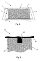
- FIG. 1 shows a schematic representation of a heatable vehicle windscreen 1.
- the heatable vehicle windscreen 1 consists of two panes of glass with a PVB interlayer extending between the panes.
- There is a heater array 3 comprising a plurality of heater wires 4 laminated in between the glass panes (for clarity, only three of the heater wires are indicated by reference numeral 4).
- the heater wires are spaced from one another in a substantially uniform manner, being arranged such that adjacent wires do not contact one another.
- the heater wires are not linear, having an approximate sinusoidal configuration, as is common in the art. Linear heater wires may be used.
- each heater wire is less than 0.1 mm thick and they are configured such that the heater array has sufficient heating when connected to the car battery.
- the dimensions of the heatable vehicle windscreen 1 are such that the major face is about 2m wide by 1m tall.
- a heatable vehicle windscreen is between 4mm and 6mm thick, having a typical construction comprising two 2.1mm thick sheets of float glass joined by a PVB interlayer having a thickness of 0.76mm.
- the heater array is arranged to be connectable to a power supply so that electrical current may pass through each heater wire, thereby heating the wire.
- the lower ends of each heater wire 4 are electrically connected to lower busbar 5.
- the upper ends of each heater wire 4 are electrically connected to upper busbar 7.
- Each busbar 5, 7 has a respective lead 9, 11 connected thereto.
- the heater array is connectable to a power supply via the busbars 5, 7 by connecting each lead 9, 11 to the terminals of the power supply.
- other suitable electrical connection means may be used, for example, additional wires, cables, leads, tags, plugs, spades and their corresponding sockets.
- a band of screen print 13 Located around the periphery of the windscreen is a band of screen print 13, usually black in colour (for clarity the band of screen print is shown in white in Figure 1 ).
- the band of screen print 13 is used to obscure the busbars that supply power to the heater wires.
- the band of screen print is referred to as an obscuration band.
- the obscuration band serves to hide the receiving flange of the vehicle bodywork when the windscreen is glazed in position in the appropriate aperture in the vehicle.
- the heater array 3 is configured such that when a sufficiently high electrical current is passed through the heater wires, the wires become hot and are able to demist or de-ice the windscreen.
- the characteristics of the heater array that may be of concern to a vehicle manufacturer includes the separation of individual heater wires, the average separation of all the heater wires in the array, the number of non-functioning heater wires (for example due to a missing heater wire or a broken heater wire), the number of heater wires in between non-functioning heater wires and the number of heater wires in contact.
- the relevant criteria required to assess functionality of the heatable vehicle windscreen may vary.
- the heatable vehicle windscreen may comprise two adjacent heater arrays, each heater array being independently heatable, each having a pair of busbars associated therewith. In such a configuration, there is a small gap between the adjacent heater arrays.
- FIG 2 shows an upper portion of another heatable vehicle windscreen 21.
- the heatable vehicle windscreen 1 there is a heater array 23 comprising a plurality of heater wires 24 laminated in between a pair of glass plies in a manner known to one skilled in the art. For clarity, only three heater wires are indicated by reference numeral 24. There is a black obscuration around the periphery of the heatable vehicle windscreen (only a portion of the obscuration band 25 is shown).
- Extending from the obscuration band 25 toward the central region of the windscreen is another screen printed region 27 that covers a portion of the inner surface of the windscreen, thereby making it not possible to view the heater wires beneath the screen print in that region.
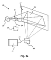
- FIG 3a shows a schematic representation of an apparatus used to inspect the heater array of a heatable vehicle glazing.
- the apparatus 29 comprises an electric arc lamp 30 for illuminating the heatable vehicle windscreen 31.
- the heatable vehicle windscreen is of the type as described with reference to figure 1 .
- the heater array of the heatable vehicle windscreen is in electrical communication with a power supply 33 via cable 34.
- the power supply may be a conventional 12V car battery.
- Light from lamp 30 is transmitted through the glazing 31 and casts a shadowgraph 35 onto the screen 37.
- a digital camera 39 is arranged to collect light reflected off the screen, thereby acquiring an image of the shadowgraph.
- the digital camera 39 is in electrical communication with a computer 41 via a suitable cable 43.
- Shadowgraph images acquired by the digital camera are stored and subsequently analysed by the computer.
- the apparatus 29 is located in a dark room environment to reduce effects of ambient light and to make the shadowgraph easily viewable on the screen 37.
- the power supply 33 must be able to supply a sufficiently high electrical current such that the heater wires are viewable in the shadowgraph image 35 that is projected onto screen 37 when illuminated by lamp 30.
- the heater array wires When no electrical current is passed through the heater array wires, it is difficult to identify the shadow of the individual wires in the shadowgraph image, as shown in figure 4 .
- a sufficiently high current is passed through the wires, for example by connecting the heater array to a conventional 12V car battery, and the glazing is illuminated, the individual heater wires are observable in the shadowgraph image, as shown in figure 5 .
- the electrical current supplied to the heater array may be adjusted to make the heater wires easier to view in the shadowgraph image.
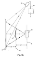
- Figure 3b shows a plan view of the apparatus shown in figure 3a .
- the line 44 represents an axis that is coincident with the lamp 30, and is parallel to the screen 37.
- the line 45 represents an axis that runs through the heatable vehicle glazing and is parallel to the heatable vehicle windscreen 37 and the line 44.
- the separation of the lamp 30 and the heatable vehicle windscreen 31 is represented by the distance 47 and is in the region of 3m to 4m when measurements are made.
- the distance of the heatable vehicle windscreen 31 from the screen 37 when measurements are made is represented by the distance 49 and is in the region of 1m to 2m.
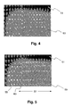
- Figure 4 shows a shadowgraph image of a heatable vehicle windscreen when no electrical current is passing through the heater wires of the heater array.
- the image shows a portion of the black obscuration band 51 and a portion 53 of the central region of the windscreen.
- the individual wires in the array of heater wires are not able to be sufficiently resolved such that the shadowgraph image is not usable for subsequent calculations.
- Such a shadowgraph image may however be used as a reference shadowgraph image for use in subsequent calculations.
- Figure 5 shows a shadowgraph image of the same heatable vehicle windscreen used to produce the reference shadowgraph image of figure 4 , except the heater array is connected to an electrical power supply. There is sufficient electrical current passing through the heater wires in the heater array such that the heater wires are easily observable in the shadowgraph image.
- Such a shadowgraph image is referred to as an active shadowgraph image.
- the active shadowgraph image shows the black obscuration band 51, a portion 55 of the heatable windscreen wherein there are no heater wires and a region 57 of the heatable windscreen wherein there is a portion of the heater array of heater wires. Within the region 57 there are a number of substantially parallel heater wires 59.
- the heater wires have an approximate sinusoidal configuration, but the heater wires may be linear.
- the active shadowgraph image clearly shows a region 60 bounded by two heater wires wherein no heater wire is visible in the active shadowgraph image. This may be due to there being no heater wire present in the heater array in that region, or there may be an electrical connection problem preventing electrical current from passing through the wire in that region. In any event, such a region void of a heater wire may be unacceptable to the function of the heater array because the heater array may not produce the required heating effect to adequately de-ice or demist the windscreen in that region.
- the active shadowgraph image of the heatable glazing may be formed without the use of a screen.
- a technique is known as “Focused” Shadowgraphy and is described in the text book “ Schlieren and Shadowgraph Techniques - Visualizing Phenomena in Transparent Media; pp. 155-159; G. S. Settles; Springer-Verlag; (2001); ISBN 3-540-66155-7 ".
- the technique as applied to the present invention is described with reference to figure 6 .
- light from a light source 61 is directed onto lens 63 to produce a collimated beam of light.
- a suitable light source is a light emitting diode (LED).
- the collimated beam of light is directed towards the heatable glazing 65 (of the type described with reference to figure 1 ) and a shadowgraph image of the glazing is produced at plane 67.
- the light is then collected by lens 69.
- a focussing lens 71 is used to image the shadowgraph at the plane 67 onto an imaging sensor 73 such as a camera, in particular a digital camera.
- An advantage of this technique is that dark room conditions are not required.
- the lenses 63, 69 may be replaced by suitable mirrors.
- the shadowgraph image at plane 67 may be acquired in a single exposure or in a strip-like fashion by using a suitable lens/mirror/light arrangement. For example, by using strip mirrors a strip of collimated light may be produced and the glazing 65 may be moved relative to the strip of collimated light such that only a portion of the glazing is illuminated at a time. A suitable strip-like detector may be used to image the portion of the shadowgraph thereby produced at plane 67. The entire shadowgraph image may be formed by collecting the appropriate number of portions.
- the active shadowgraph image obtained by the focussed shadowography technique may be analysed in the same way as the shadowgraph image obtained by projecting the shadowgraph onto a screen.
- a reference shadowgraph image of the glazing may be obtained using the apparatus shown in Figure 6 by making measurements without the heater array being connected to a power supply such that the heater wires are at ambient temperature.
- the active shadowgraph image obtained when sufficient electrical current is passed through the heater array such that the heater wires are observable in the shadowgraph image may be used for subsequent calculations.
- the active shadowgraph image When projected onto a screen, the active shadowgraph image may be inspected manually and the number of non-functioning heater wires determined.
- the active shadowgraph image is captured by a camera and subsequently analysed. The analysis may be carried out manually, but it is preferred that the subsequent analysis be carried out by a computer.
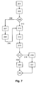
- Figure 7 is a block diagram illustrating the steps involved in a method of inspecting a heatable glazing according the first aspect of the invention.
- a heatable glazing comprising a heater array having at least one heater wire is positioned such that the glazing may be illuminated by a suitably positioned light source.
- an imaging sensor is also suitably located such that light transmitted through the glazing, thereby producing a shadowgraph image of the glazing, may be collected by the imaging sensor, either by direct illumination thereof or by capturing the reflection of the shadowgraph image off a screen.
- the imaging sensor is a digital camera.
- step 203 With no power supply connected to the heater array such that no electrical current passes through the heater wires, the heatable glazing is illuminated with the light source thereby producing a shadowgraph image of the heatable glazing.
- Step 205 is a decision point wherein it is decided whether a reference shadowgraph image of the glazing should be measured in addition to an active shadowgraph image of the heatable glazing. If a reference shadowgraph image of the glazing is to be measured, path 206 is followed.
- the shadowgraph image is captured by the imaging sensor.
- the shadowgraph image captured in step 207 is stored in a computer and set as the reference shadowgraph image of the heatable glazing. The method then follows path 210 to step 213.
- decision point 205 follows path 212 to step 213.
- the illumination conditions when the active shadowgraph image is captured will be the same, or substantially the same, as the illumination conditions when the reference shadowgraph image was captured.
- a reference shadowgraph image and an active shadowgraph image are measured, by having the same, or substantially the same, illumination conditions, it is much simpler to compensate the active shadowgraph image for the reference shadowgraph image.
- the heater array of the heatable glazing is connected to a suitable power supply and an electrical current is passed through the heater array.
- Sufficient electrical current should be passed through the heater array such that the heater wires are observable in the shadowgraph image produced when the heatable glazing is illuminated by the light source. Too high an electrical current may damage the heater wires.
- the shadowgraph image of the heatable glazing is captured by the imaging sensor.
- the shadowgraph image captured in step 214 is stored in a computer and set as the active shadowgraph image of the heatable glazing.
- Step 217 is another decision point wherein subsequent analysis of the shadowgraph image or images captured in the preceding steps depends on whether a reference shadowgraph image was measured or not. If a reference shadowgraph image was measured, path 218 is followed.
- the optical effects in the active shadowgraph image produced by other artefacts not related to the heater array, for example dust on one of the surfaces of the heatable glazing are reduced or effectively eliminated by correction of the active shadowgraph image with respect to the reference shadowgraph image. This may be done by dividing the active shadowgraph image by the reference shadowgraph image or subtracting the reference shadowgraph image from the active shadowgraph image. This operation is carried out at step 219 to produce what shall be referred to as a difference shadowgraph image of the heatable glazing.
- step 221 the difference shadowgraph image of the heatable glazing is analysed.
- decision point 217 follows path 223.
- the active shadowgraph image is analysed.
- the analysis routine used to analyse the active shadowgraph image at step 224 may be the same as the analysis routines used to analyse the difference shadowgraph image at step 221.
- the results of the analysis are presented such that the relevant parameters of the heater array of the heatable glazing may be compared with the specification for such parameters.
- the exact analysis carried out on the difference shadowgraph image at step 221 or the active shadowgraph image at step 224 depends upon the characteristics of the heater array that are important. Different characteristics may have a different degree of importance depending upon the particular application of the heatable glazing.
- the shadowgraph image may be thresholded using conventional thresholding techniques.
- the thresholded image may then be subsequently analysed.
- One possible technique is to analyse the thresholded shadowgraph image using a number of parallel linescans across the image, as illustrated in figure 8 .
- Figure 8 shows a portion of an active shadowgraph or difference shadowgraph image that has been thresholded such that the wires are distinguishable from the background.
- a heater wire was not observable in the active shadowgraph image of the heater array and is shown as a dotted line 86; this heater wire was missing from the shadowgraph image of the array, for example as described with reference to region 60 of figure 4 .
- each heater wire with each linescan can be found.
- the linescan 91 intersects the wire 81 at the point 101 as indicated by the white dot.
- the intersection of the linescans with the heating wires is indicated by a white dot at the point of intersection.
- the spacing of the heater wires is non-uniform and there is a missing wire (as indicated by the dotted line 86).
- the uniformity of the heater wire spacing may be within a predetermined specification for the spacing of the heater wires in the heater array.
- part of the heater array at the upper centre may be obscured by a region of black print.
- a region of black print is used when additional components are bonded to the inner surface of the glazing, for example a rear view mirror stem.
- the obscuration band extends into the heater array as shown in figure 2 , it is not possible to directly measure the shadowgraph image of the heater wires in this region.
- One option is to simply ignore measurements of the regions adjacent to the printed region.
- Another option is to consider regions either side of the printed region and measure those regions alone. For a particular glazing, acceptable characteristics of the heater array in these regions could be defined.
- Another alternative is to extrapolate the heater wires into the region wherein measurement is not possible. To extrapolate reliably, it may be necessary to increase the number of linescan measurements.
- the heater wires are shown as having an undulating form, the heater wires may be linear.
- Methods in accordance with the first aspect of the invention may be useful in detecting non-working electrical conductors that are incorporated into a laminated construction.
- the technique may be useful with certain laminated antennae systems.
- any electrical conductor that is embedded in an optically transparent glazing medium could be assessed by measuring a shadowgraph image of the glazing when sufficient electrical current passes through the electrical conductor such that the electrical conductor is observable in the shadowgraph image.
- the glazing may have an outer surface of a plastics material such as polycarbonate.
- the glazing may be a bilayer construction, for example consisting of a sheet of glass with a layer of PVB.
- the electrical conductor may be embedded in the body of the glazing medium, for example a panel made of a suitable plastic material.
Description
- The present invention relates to the optical inspection of vehicle glazings, in particular to the optical inspection of a heatable laminated glazing comprising an array of heater wires laminated between a pair of glass sheets.
- In the automotive field, it is well known that windscreens have a laminated construction for safety reasons. A standard feature of a vehicle is the inclusion of a fan assembly designed to blow air onto the inner surface of the vehicle windscreen to demist the inner surface, thereby removing condensation from the inner surface thereof and improving the driver's visibility through the glazing. In particularly cold weather, when ice may form on the inner or outer surfaces of the vehicle windscreen, it is well known that the fan may be used to remove the ice from the windscreen by blowing warm air onto the windscreen, thereby de-icing the windscreen.
- In addition to the fan assembly, some vehicles may also have a heatable windscreen, wherein laminated between the plies of the windscreen is a heater array that is connectable to the car battery. The heater array comprises a plurality of spaced electrical conductors, each in the form of fine wires, often known as heater wires. When the electrical connection between the heater array and the car battery is made, an electrical current passes through the heater array causing the heater wires to heat up. This provides localised heating of the windscreen in the vicinity of the heater array that is sufficient to remove ice from the windscreen. Such electrically heatable windows may be installed in cars, boats, aircraft and buildings. A construction of a laminated transparent panel incorporating heater wires is described in
GB 972,453 - An important consideration in the construction of such heatable laminated glazings is that the heater array is able to uniformly remove ice and/or condensation from the glazing surfaces. When such a heatable glazing is used as a vehicle windscreen, the vehicle manufacturer usually specifies the requirements of the heater array, such as the electrically resistance of the wires, the material characteristics of the wires, the configuration of the wires (whether straight or not), the thickness of each wire, the length of each wire, the number of active heater wires and their separation. Usually the heater wires are uniformly spaced from the top of the windscreen to bottom i.e. they should be parallel, wherein the top of the windscreen refers to that edge nearest the roof of the vehicle in the installed position. Due to the procedure used to manufacture such a heatable glazing, it is possible that pairs of heater wires in the array may contact each other, thereby electrically shorting out and as a consequence not providing a sufficiently uniform heating. Additional problems may be that the heater array has missing heater wires, heater wires that cross or heater wires that are inoperative for other reasons.
- Prior to installing such a heatable glazing, for example a heatable windscreen in a car, it is desirable to inspect the heater array to ensure that the characteristics are acceptable so that the heater array is able to adequately function.
- In a related technical field, it is known to inspect a heater grid printed on a surface of a vehicle glazing by passing an electrical current through the heater grid and using a thermal imaging camera to produce a temperature distribution profile. Such a system does not have particularly high spatial resolution and is not suitable for use with embedded heater wires as is the case with laminated heated windscreens. Additionally such systems are not able to resolve the individual heater wires since only global temperature profiles are obtained. An example of such a system is described in
US2004/0124358A1 . - In
JP6249905A - Commercially available systems are available for inspecting heatable automotive windscreens. Such systems are able to inspect the function of each individual heating wire. A system known as G/GLAS Wired windscreen inspection is supplied by Graphikon GmbH of Mandelstr. 16, 10409 Berlin, Germany (www.graphikon.de). The inspection system consists of a motorized scanning unit which is driven along the glass. The exact distance of the scanning unit to the glass surface is controlled automatically by a non-contact sensor. The system detects inactive and missing wires. Such a system suffers from the problem that in order to detect defective heater wires, the windscreen is scanned a line at a time. To map a portion of the entire heated area requires the portion to be scanned in a raster fashion which is a time consuming process.
-
US2003/0151739A1 discloses an apparatus and method for quantitatively measuring ripple and distortion levels in a transparent sheet material. - There is therefore a need for a method and apparatus for inspecting a heatable glazing, in particular a laminated heatable vehicle windscreen that comprises a heater array laminated between a pair of glass plies, which at least partially overcomes the problems of known inspection systems.
- Accordingly the present invention provides from a first aspect a method of inspecting a heatable glazing, the heatable glazing comprising a heater array comprising a heater wire, the method comprising the steps
- (i) illuminating the heatable glazing with a light source to produce a shadowgraph image of the heatable glazing;
- (ii) passing a sufficiently high electrical current through the heater array such that the heater wire is observable in the shadowgraph image of the heatable glazing, such a shadowgraph image of the heatable glazing being referred to as an active shadowgraph image of the heatable glazing; and
- (iii) capturing the active shadowgraph image with an imaging sensor.
- It has been found that when a sufficiently high electrical current is passed through the heating wires of the heater array that is laminated between the plies of a heatable vehicle windscreen, the heater wires are observable in the shadowgraph image. Without being bound by any particular theory, it is thought that as the heater wire gets hot due to the passage of electrical current therethrough, the refractive index of the surrounding medium changes allowing the heater wire to be observable in the shadowgraph image.
- When the heater wire is observable in the shadowgraph image, such a shadowgraph image is referred to as an active shadowgraph image. The electrical current that is passed through the heater should be sufficient such that the heater wire is observable in the shadowgraph image. When insufficient electrical current passes through the heater wire, the heater wire is not observable in the shadowgraph image. In the above method, step (ii) may precede step (i).
- A method in accordance with the first aspect of the present invention allows the heater array in a heatable glazing to be rapidly inspected.
- Preferably the active shadowgraph image is projected onto a screen, and the imaging sensor captures the active shadowgraph image that is projected onto the screen.
- In alternative embodiments of the first aspect of the present invention, the active shadowgraph image is not projected onto a screen, but is instead projected onto a plane in space, and the imaging sensor focuses onto the plane in space to capture the active shadowgraph image.
- In other embodiments of the first aspect of the present invention, the method comprises the step of illuminating the glazing when insufficient electrical current is passing through the heater array such that the heater wire is not observable in the shadowgraph image, thereby producing a reference shadowgraph image of the heatable glazing, capturing the reference shadowgraph image, and comparing the active shadowgraph image of the heatable glazing with the reference shadowgraph image of the heatable glazing.
- Preferably no electrical current passes through the heater array when the reference shadowgraph image is produced.
- Preferably the reference shadowgraph image is captured before the active shadowgraph image. This ensures that the heatable glazing is at ambient conditions when the reference shadowgraph image is captured.
- By comparing the active shadowgraph image with the reference shadow image, a difference shadowgraph image may be produced. This has the advantage that by carrying out subsequent analysis on the difference shadowgraph image, the effects of dirt on the surface of the glazing may be reduced, as may other optical effects associated with defects in the body of the glazing, such as bubbles and ream that may contribute to the active shadowgraph image making subsequent analysis difficult. It has been found that these spurious effects can be almost entirely removed by measuring the reference shadow graph image with little or no electrical current passing through the heater array and removing the effects of the reference shadowgraph image from the active shadowgraph image. The reference shadowgraph image of the heatable glazing may be subtracted from the active shadowgraph image of the heatable glazing. Alternatively, the active shadowgraph image of the heatable glazing may be divided by the reference shadowgraph image of the heatable glazing.
- Usually the heater array comprises a plurality of heater wires. Preferably the method is used to determine the average spacing of the heater wires.
- Preferably the method is used to determine the existence of a non-functioning heater wire.
- Preferably the imaging sensor is part of a camera, preferably a digital camera.
- The present invention also provides from a second aspect an apparatus for inspecting a heater wire laminated within a heatable glazing, the apparatus comprising a light source for illuminating the heatable glazing to produce a shadowgraph image of the glazing, an imaging sensor to acquire the shadowgraph image and a power supply for applying sufficient electrical current to the heater wire such that the heater wire is observable in the shadowgraph image of the glazing.
- From a third aspect, the present invention provides use of a shadowgraph image for inspecting a heatable glazing comprising a heater array having at least one heater wire.
- Embodiments of the present invention will now be described by way of example only with reference to the following figures (not to scale) in which,
-
Figure 1 shows a schematic representation of a heatable vehicle windscreen; -
Figure 2 shows an upper portion of a heatable vehicle windscreen; -
Figure 3a shows a schematic representation of an apparatus used to inspect the heater array in a heatable vehicle glazing; -
Figure 3b is a plan view of the apparatus shown infigure 3a ; -
Figure 4 is a photograph of a shadowgraph image of a heatable vehicle windscreen wherein the heater wires are not observable; -
Figure 5 is a photograph of a shadowgraph image of a heatable vehicle windscreen wherein the heater wires are observable; -
Figure 6 shows an arrangement for measuring a shadowgraph image of a heatable vehicle windscreen without the use of a screen but instead focussing on a plane in space; -
Figure 7 illustrates the steps involved in determining the characteristics of a heater array that is part of a heatable glazing; and -
Figure 8 illustrates one method for analysing the shadowgraph image of the heatable vehicle windscreen. -
Figure 1 shows a schematic representation of aheatable vehicle windscreen 1. Theheatable vehicle windscreen 1 consists of two panes of glass with a PVB interlayer extending between the panes. There is aheater array 3 comprising a plurality ofheater wires 4 laminated in between the glass panes (for clarity, only three of the heater wires are indicated by reference numeral 4). The heater wires are spaced from one another in a substantially uniform manner, being arranged such that adjacent wires do not contact one another. The heater wires are not linear, having an approximate sinusoidal configuration, as is common in the art. Linear heater wires may be used. Typically each heater wire is less than 0.1 mm thick and they are configured such that the heater array has sufficient heating when connected to the car battery. The dimensions of theheatable vehicle windscreen 1 are such that the major face is about 2m wide by 1m tall. Typically a heatable vehicle windscreen is between 4mm and 6mm thick, having a typical construction comprising two 2.1mm thick sheets of float glass joined by a PVB interlayer having a thickness of 0.76mm. - The heater array is arranged to be connectable to a power supply so that electrical current may pass through each heater wire, thereby heating the wire. The lower ends of each
heater wire 4 are electrically connected to lowerbusbar 5. The upper ends of eachheater wire 4 are electrically connected toupper busbar 7. Eachbusbar respective lead busbars lead busbars - Located around the periphery of the windscreen is a band of
screen print 13, usually black in colour (for clarity the band of screen print is shown in white inFigure 1 ). The band ofscreen print 13 is used to obscure the busbars that supply power to the heater wires. Usually the band of screen print is referred to as an obscuration band. Additionally the obscuration band serves to hide the receiving flange of the vehicle bodywork when the windscreen is glazed in position in the appropriate aperture in the vehicle. - The
heater array 3 is configured such that when a sufficiently high electrical current is passed through the heater wires, the wires become hot and are able to demist or de-ice the windscreen. - The characteristics of the heater array that may be of concern to a vehicle manufacturer includes the separation of individual heater wires, the average separation of all the heater wires in the array, the number of non-functioning heater wires (for example due to a missing heater wire or a broken heater wire), the number of heater wires in between non-functioning heater wires and the number of heater wires in contact. Depending upon the particular vehicle manufacturer, the relevant criteria required to assess functionality of the heatable vehicle windscreen may vary.
- In an alternative configuration, the heatable vehicle windscreen may comprise two adjacent heater arrays, each heater array being independently heatable, each having a pair of busbars associated therewith. In such a configuration, there is a small gap between the adjacent heater arrays.
-
Figure 2 shows an upper portion of anotherheatable vehicle windscreen 21. As for theheatable vehicle windscreen 1, there is aheater array 23 comprising a plurality ofheater wires 24 laminated in between a pair of glass plies in a manner known to one skilled in the art. For clarity, only three heater wires are indicated byreference numeral 24. There is a black obscuration around the periphery of the heatable vehicle windscreen (only a portion of theobscuration band 25 is shown). - Extending from the
obscuration band 25 toward the central region of the windscreen is another screen printedregion 27 that covers a portion of the inner surface of the windscreen, thereby making it not possible to view the heater wires beneath the screen print in that region. -
Figure 3a shows a schematic representation of an apparatus used to inspect the heater array of a heatable vehicle glazing. Theapparatus 29 comprises anelectric arc lamp 30 for illuminating theheatable vehicle windscreen 31. The heatable vehicle windscreen is of the type as described with reference tofigure 1 . The heater array of the heatable vehicle windscreen is in electrical communication with apower supply 33 viacable 34. The power supply may be a conventional 12V car battery. Light fromlamp 30 is transmitted through theglazing 31 and casts ashadowgraph 35 onto thescreen 37. Adigital camera 39 is arranged to collect light reflected off the screen, thereby acquiring an image of the shadowgraph. Thedigital camera 39 is in electrical communication with acomputer 41 via asuitable cable 43. Shadowgraph images acquired by the digital camera are stored and subsequently analysed by the computer. Theapparatus 29 is located in a dark room environment to reduce effects of ambient light and to make the shadowgraph easily viewable on thescreen 37. Thepower supply 33 must be able to supply a sufficiently high electrical current such that the heater wires are viewable in theshadowgraph image 35 that is projected ontoscreen 37 when illuminated bylamp 30. - When no electrical current is passed through the heater array wires, it is difficult to identify the shadow of the individual wires in the shadowgraph image, as shown in
figure 4 . When a sufficiently high current is passed through the wires, for example by connecting the heater array to a conventional 12V car battery, and the glazing is illuminated, the individual heater wires are observable in the shadowgraph image, as shown infigure 5 . The electrical current supplied to the heater array may be adjusted to make the heater wires easier to view in the shadowgraph image. -
Figure 3b shows a plan view of the apparatus shown infigure 3a . Theline 44 represents an axis that is coincident with thelamp 30, and is parallel to thescreen 37. Theline 45 represents an axis that runs through the heatable vehicle glazing and is parallel to theheatable vehicle windscreen 37 and theline 44. The separation of thelamp 30 and theheatable vehicle windscreen 31 is represented by thedistance 47 and is in the region of 3m to 4m when measurements are made. The distance of theheatable vehicle windscreen 31 from thescreen 37 when measurements are made is represented by thedistance 49 and is in the region of 1m to 2m. -
Figure 4 shows a shadowgraph image of a heatable vehicle windscreen when no electrical current is passing through the heater wires of the heater array. The image shows a portion of theblack obscuration band 51 and aportion 53 of the central region of the windscreen. The individual wires in the array of heater wires are not able to be sufficiently resolved such that the shadowgraph image is not usable for subsequent calculations. Such a shadowgraph image may however be used as a reference shadowgraph image for use in subsequent calculations. -
Figure 5 shows a shadowgraph image of the same heatable vehicle windscreen used to produce the reference shadowgraph image offigure 4 , except the heater array is connected to an electrical power supply. There is sufficient electrical current passing through the heater wires in the heater array such that the heater wires are easily observable in the shadowgraph image. Such a shadowgraph image is referred to as an active shadowgraph image. The active shadowgraph image shows theblack obscuration band 51, aportion 55 of the heatable windscreen wherein there are no heater wires and aregion 57 of the heatable windscreen wherein there is a portion of the heater array of heater wires. Within theregion 57 there are a number of substantiallyparallel heater wires 59. The heater wires have an approximate sinusoidal configuration, but the heater wires may be linear. The active shadowgraph image clearly shows aregion 60 bounded by two heater wires wherein no heater wire is visible in the active shadowgraph image. This may be due to there being no heater wire present in the heater array in that region, or there may be an electrical connection problem preventing electrical current from passing through the wire in that region. In any event, such a region void of a heater wire may be unacceptable to the function of the heater array because the heater array may not produce the required heating effect to adequately de-ice or demist the windscreen in that region. - In an alternative embodiment, the active shadowgraph image of the heatable glazing may be formed without the use of a screen. Such a technique is known as "Focused" Shadowgraphy and is described in the text book "Schlieren and Shadowgraph Techniques - Visualizing Phenomena in Transparent Media; pp. 155-159; G. S. Settles; Springer-Verlag; (2001); ISBN 3-540-66155-7". The technique as applied to the present invention is described with reference to
figure 6 . - In
figure 6 , light from alight source 61 is directed ontolens 63 to produce a collimated beam of light. A suitable light source is a light emitting diode (LED). The collimated beam of light is directed towards the heatable glazing 65 (of the type described with reference tofigure 1 ) and a shadowgraph image of the glazing is produced atplane 67. The light is then collected bylens 69. A focussinglens 71 is used to image the shadowgraph at theplane 67 onto animaging sensor 73 such as a camera, in particular a digital camera. An advantage of this technique is that dark room conditions are not required. Thelenses - The shadowgraph image at
plane 67 may be acquired in a single exposure or in a strip-like fashion by using a suitable lens/mirror/light arrangement. For example, by using strip mirrors a strip of collimated light may be produced and theglazing 65 may be moved relative to the strip of collimated light such that only a portion of the glazing is illuminated at a time. A suitable strip-like detector may be used to image the portion of the shadowgraph thereby produced atplane 67. The entire shadowgraph image may be formed by collecting the appropriate number of portions. - The active shadowgraph image obtained by the focussed shadowography technique (i.e. without projection onto a screen) may be analysed in the same way as the shadowgraph image obtained by projecting the shadowgraph onto a screen.
- Again, a reference shadowgraph image of the glazing may be obtained using the apparatus shown in
Figure 6 by making measurements without the heater array being connected to a power supply such that the heater wires are at ambient temperature. - In one embodiment of the first aspect of the present invention, the active shadowgraph image obtained when sufficient electrical current is passed through the heater array such that the heater wires are observable in the shadowgraph image may be used for subsequent calculations. When projected onto a screen, the active shadowgraph image may be inspected manually and the number of non-functioning heater wires determined. Preferably the active shadowgraph image is captured by a camera and subsequently analysed. The analysis may be carried out manually, but it is preferred that the subsequent analysis be carried out by a computer.
- A method in accordance with the first aspect of the invention shall now be described with reference to
figure 7. Figure 7 is a block diagram illustrating the steps involved in a method of inspecting a heatable glazing according the first aspect of the invention. - At
step 201, a heatable glazing comprising a heater array having at least one heater wire is positioned such that the glazing may be illuminated by a suitably positioned light source. At this step, an imaging sensor is also suitably located such that light transmitted through the glazing, thereby producing a shadowgraph image of the glazing, may be collected by the imaging sensor, either by direct illumination thereof or by capturing the reflection of the shadowgraph image off a screen. Preferably the imaging sensor is a digital camera. - The method then moves to step 203. With no power supply connected to the heater array such that no electrical current passes through the heater wires, the heatable glazing is illuminated with the light source thereby producing a shadowgraph image of the heatable glazing.
- Step 205 is a decision point wherein it is decided whether a reference shadowgraph image of the glazing should be measured in addition to an active shadowgraph image of the heatable glazing. If a reference shadowgraph image of the glazing is to be measured,
path 206 is followed. - At
step 207, the shadowgraph image is captured by the imaging sensor. - At
step 209, the shadowgraph image captured instep 207 is stored in a computer and set as the reference shadowgraph image of the heatable glazing. The method then followspath 210 to step 213. - If no reference shadowgraph is to be measured,
decision point 205 followspath 212 to step 213. - Since the heatable glazing is already illuminated at
step 203, the illumination conditions when the active shadowgraph image is captured will be the same, or substantially the same, as the illumination conditions when the reference shadowgraph image was captured. When a reference shadowgraph image and an active shadowgraph image are measured, by having the same, or substantially the same, illumination conditions, it is much simpler to compensate the active shadowgraph image for the reference shadowgraph image. - At
step 213, the heater array of the heatable glazing is connected to a suitable power supply and an electrical current is passed through the heater array. Sufficient electrical current should be passed through the heater array such that the heater wires are observable in the shadowgraph image produced when the heatable glazing is illuminated by the light source. Too high an electrical current may damage the heater wires. - At
step 214, with the heater wires observable in the shadowgraph image, the shadowgraph image of the heatable glazing is captured by the imaging sensor. - At
step 215, the shadowgraph image captured instep 214 is stored in a computer and set as the active shadowgraph image of the heatable glazing. - Step 217 is another decision point wherein subsequent analysis of the shadowgraph image or images captured in the preceding steps depends on whether a reference shadowgraph image was measured or not. If a reference shadowgraph image was measured,
path 218 is followed. - At
step 219, the optical effects in the active shadowgraph image produced by other artefacts not related to the heater array, for example dust on one of the surfaces of the heatable glazing are reduced or effectively eliminated by correction of the active shadowgraph image with respect to the reference shadowgraph image. This may be done by dividing the active shadowgraph image by the reference shadowgraph image or subtracting the reference shadowgraph image from the active shadowgraph image. This operation is carried out atstep 219 to produce what shall be referred to as a difference shadowgraph image of the heatable glazing. - At
step 221, the difference shadowgraph image of the heatable glazing is analysed. - If no reference shadowgraph image was measured,
decision point 217 followspath 223. - At
step 224, the active shadowgraph image is analysed. The analysis routine used to analyse the active shadowgraph image atstep 224 may be the same as the analysis routines used to analyse the difference shadowgraph image atstep 221. - At
step 225, the results of the analysis are presented such that the relevant parameters of the heater array of the heatable glazing may be compared with the specification for such parameters. - The exact analysis carried out on the difference shadowgraph image at
step 221 or the active shadowgraph image atstep 224 depends upon the characteristics of the heater array that are important. Different characteristics may have a different degree of importance depending upon the particular application of the heatable glazing. - At
step - One possible technique is to analyse the thresholded shadowgraph image using a number of parallel linescans across the image, as illustrated in
figure 8 . -
Figure 8 shows a portion of an active shadowgraph or difference shadowgraph image that has been thresholded such that the wires are distinguishable from the background. There are five heater wires shown, 81, 82, 83, 84 and 85. A heater wire was not observable in the active shadowgraph image of the heater array and is shown as a dottedline 86; this heater wire was missing from the shadowgraph image of the array, for example as described with reference toregion 60 offigure 4 . There are six linescans shown as dashedlines - Using a linescan approach, the intersection of each heater wire with each linescan can be found. For example, with reference to
figure 8 , thelinescan 91 intersects thewire 81 at thepoint 101 as indicated by the white dot. The intersection of the linescans with the heating wires is indicated by a white dot at the point of intersection. For the portion of the heater array shown infigure 8 , the spacing of the heater wires is non-uniform and there is a missing wire (as indicated by the dotted line 86). The uniformity of the heater wire spacing may be within a predetermined specification for the spacing of the heater wires in the heater array. - Depending upon the configuration of the obscuration band, as illustrated by
figure 2 , part of the heater array at the upper centre may be obscured by a region of black print. Such a region is used when additional components are bonded to the inner surface of the glazing, for example a rear view mirror stem. When the obscuration band extends into the heater array as shown infigure 2 , it is not possible to directly measure the shadowgraph image of the heater wires in this region. One option is to simply ignore measurements of the regions adjacent to the printed region. Another option is to consider regions either side of the printed region and measure those regions alone. For a particular glazing, acceptable characteristics of the heater array in these regions could be defined. - Another alternative is to extrapolate the heater wires into the region wherein measurement is not possible. To extrapolate reliably, it may be necessary to increase the number of linescan measurements.
- Although in the previous figures the heater wires are shown as having an undulating form, the heater wires may be linear.
- Methods in accordance with the first aspect of the invention may be useful in detecting non-working electrical conductors that are incorporated into a laminated construction. For example, the technique may be useful with certain laminated antennae systems.
- Additionally, any electrical conductor that is embedded in an optically transparent glazing medium could be assessed by measuring a shadowgraph image of the glazing when sufficient electrical current passes through the electrical conductor such that the electrical conductor is observable in the shadowgraph image. For example, the glazing may have an outer surface of a plastics material such as polycarbonate. Alternatively, the glazing may be a bilayer construction, for example consisting of a sheet of glass with a layer of PVB. The electrical conductor may be embedded in the body of the glazing medium, for example a panel made of a suitable plastic material.
Claims (14)
- A method of inspecting a heatable glazing (1, 21, 31, 65), the heatable glazing comprising a heater array (3, 23) comprising a heater wire (4, 24), the method comprising the steps(i) illuminating the heatable glazing with a light source (30, 61) to produce a shadowgraph image of the heatable glazing;(ii) passing a sufficiently high electrical current through the heater array such that the heater wire is observable in the shadowgraph image of the heatable glazing, such a shadowgraph image of the heatable glazing being referred to as an active shadowgraph image of the heatable glazing (215); and(iii) capturing the active shadowgraph image of the heatable glazing with an imaging sensor (39, 73).
- A method according to claim 1, wherein the active shadowgraph image is projected onto a screen (37) and the imaging sensor captures the active shadowgraph image that is projected onto the screen.
- A method according to claim 1, wherein the active shadowgraph image is projected onto a plane in space, and the imaging sensor focuses onto the plane in space to capture the active shadowgraph image.
- A method according to any preceding claim, comprising the step of illuminating the glazing when insufficient electrical current is passing through the heater array such that the heater wire is not observable in the shadowgraph image, thereby producing a reference shadowgraph image of the heatable glazing, capturing the reference shadowgraph image (209), and comparing the active shadowgraph image of the heatable glazing with the reference shadowgraph image of the heatable glazing.
- A method according to claim 4, wherein the step (219) of comparing the active shadowgraph image of the heatable glazing with the reference shadowgraph image of the heatable glazing comprises subtracting the reference shadowgraph image of the heatable glazing from the active shadowgraph image of the heatable glazing.
- A method according to claim 4, wherein the step of comparing the active shadowgraph image of the heatable glazing with the reference shadowgraph image of the heatable glazing comprises dividing the active shadowgraph image of the heatable glazing by the reference shadowgraph image of the heatable glazing.
- A method according to any of the claims 4 to 6, wherein no electrical current passes through the heater array when the reference shadowgraph image is produced.
- A method according to any of the claims 4 to 7, wherein the reference shadowgraph image is captured before the active shadowgraph image.
- A method according to any preceding claim, wherein the heater array comprises a plurality of heater wires.
- A method according to claim 9, wherein the average spacing of the heater wires is determined.
- A method according to any preceding claim, wherein the existence of a non-functioning heater wire is determined.
- A method according to any preceding claim, wherein the imaging sensor is part of a camera, preferably a digital camera.
- An apparatus for inspecting a heater wire (4, 24) laminated within a heatable glazing (1, 21, 31, 65), the apparatus comprising a light source (30, 61) for illuminating the heatable glazing to produce a shadowgraph image of the glazing, an imaging sensor (39, 73) for acquiring the shadowgraph image and a power supply (33) for applying sufficient electrical current to the heater wire such that the heater wire is observable in the shadowgraph image of the glazing.
- Use of a shadowgraph image according to anyone of the claims 1 to 12, for inspecting a heatable glazing (1, 21, 31, 65), the glazing comprising a heater array (3, 23) having at least one theater wire (4, 24).
Applications Claiming Priority (2)
| Application Number | Priority Date | Filing Date | Title |
|---|---|---|---|
| GB0914651A GB0914651D0 (en) | 2009-08-21 | 2009-08-21 | Heatable glazing inspection |
| PCT/EP2010/062183 WO2011026740A1 (en) | 2009-08-21 | 2010-08-20 | Heatable glazing inspection |
Publications (2)
| Publication Number | Publication Date |
|---|---|
| EP2467704A1 EP2467704A1 (en) | 2012-06-27 |
| EP2467704B1 true EP2467704B1 (en) | 2013-08-07 |
Family
ID=41171742
Family Applications (1)
| Application Number | Title | Priority Date | Filing Date |
|---|---|---|---|
| EP20100744937 Active EP2467704B1 (en) | 2009-08-21 | 2010-08-20 | Heatable glazing inspection |
Country Status (8)
| Country | Link |
|---|---|
| US (1) | US9125246B2 (en) |
| EP (1) | EP2467704B1 (en) |
| CN (1) | CN102483382B (en) |
| BR (1) | BR112012003505A2 (en) |
| GB (1) | GB0914651D0 (en) |
| MX (1) | MX2012002026A (en) |
| RU (1) | RU2547325C2 (en) |
| WO (1) | WO2011026740A1 (en) |
Families Citing this family (21)
| Publication number | Priority date | Publication date | Assignee | Title |
|---|---|---|---|---|
| EP2803979A1 (en) * | 2013-05-17 | 2014-11-19 | Idris Arslan | Control method of laminated glasses with resistance wire and a system for the method thereof |
| CN106770361A (en) * | 2016-12-27 | 2017-05-31 | 昆山博威泰克电子科技有限公司 | A kind of full-automatic screen optical detection apparatus and detection method |
| US10289930B2 (en) * | 2017-02-09 | 2019-05-14 | Glasstech, Inc. | System and associated for online measurement of the optical characteristics of a glass sheet |
| US10197517B2 (en) | 2017-03-24 | 2019-02-05 | Rosemount Aerospace, Inc. | Probe heater remaining useful life determination |
| US10914777B2 (en) | 2017-03-24 | 2021-02-09 | Rosemount Aerospace Inc. | Probe heater remaining useful life determination |
| US11060992B2 (en) | 2017-03-24 | 2021-07-13 | Rosemount Aerospace Inc. | Probe heater remaining useful life determination |
| US10151785B2 (en) | 2017-03-24 | 2018-12-11 | Rosemount Aerospace Inc. | Probe heater remaining useful life determination |
| US10895592B2 (en) | 2017-03-24 | 2021-01-19 | Rosemount Aerospace Inc. | Probe heater remaining useful life determination |
| US10180449B2 (en) | 2017-03-24 | 2019-01-15 | Rosemount Aerospace Inc. | Probe heater remaining useful life determination |
| US10564203B2 (en) | 2017-03-24 | 2020-02-18 | Rosemount Aerospace Inc. | Probe heater remaining useful life determination |
| JP7076280B2 (en) * | 2018-04-27 | 2022-05-27 | 日立造船株式会社 | Measuring method and measuring device |
| CN108593710B (en) * | 2018-06-14 | 2020-02-11 | 湖南大学 | Thermal imaging detection system and method for surface defects of high-reflectivity material |
| JP7180305B2 (en) * | 2018-11-19 | 2022-11-30 | トヨタ自動車株式会社 | window glass heating device |
| US10962580B2 (en) | 2018-12-14 | 2021-03-30 | Rosemount Aerospace Inc. | Electric arc detection for probe heater PHM and prediction of remaining useful life |
| US11061080B2 (en) | 2018-12-14 | 2021-07-13 | Rosemount Aerospace Inc. | Real time operational leakage current measurement for probe heater PHM and prediction of remaining useful life |
| US11639954B2 (en) | 2019-05-29 | 2023-05-02 | Rosemount Aerospace Inc. | Differential leakage current measurement for heater health monitoring |
| US11472562B2 (en) | 2019-06-14 | 2022-10-18 | Rosemount Aerospace Inc. | Health monitoring of an electrical heater of an air data probe |
| US11930563B2 (en) | 2019-09-16 | 2024-03-12 | Rosemount Aerospace Inc. | Monitoring and extending heater life through power supply polarity switching |
| US11293995B2 (en) | 2020-03-23 | 2022-04-05 | Rosemount Aerospace Inc. | Differential leakage current measurement for heater health monitoring |
| US11630140B2 (en) | 2020-04-22 | 2023-04-18 | Rosemount Aerospace Inc. | Prognostic health monitoring for heater |
| CN116234691A (en) * | 2020-09-28 | 2023-06-06 | 法国圣-戈班玻璃公司 | Imaging system and method for determining defects in glazing |
Family Cites Families (22)
| Publication number | Priority date | Publication date | Assignee | Title |
|---|---|---|---|---|
| BE634939A (en) | 1962-07-16 | 1900-01-01 | ||
| US4395677A (en) | 1981-02-13 | 1983-07-26 | Chrysler Corporation | Hall Effect tester for heated window grids |
| JPH07104562B2 (en) * | 1989-06-02 | 1995-11-13 | 富士ゼロックス株式会社 | Light source for illumination of color image recording device |
| DE4206820A1 (en) | 1991-08-28 | 1993-03-04 | Bosch Siemens Hausgeraete | OVEN DOOR |
| US7596242B2 (en) * | 1995-06-07 | 2009-09-29 | Automotive Technologies International, Inc. | Image processing for vehicular applications |
| JPH06249905A (en) | 1993-02-24 | 1994-09-09 | Central Glass Co Ltd | Method and apparatus for inspection of disconnection in blur-protected glass |
| FR2720831B3 (en) * | 1994-06-02 | 1996-07-12 | Saint Gobain Vitrage | Method for measuring the optical quality of a glazing. |
| US7738678B2 (en) * | 1995-06-07 | 2010-06-15 | Automotive Technologies International, Inc. | Light modulation techniques for imaging objects in or around a vehicle |
| US7769513B2 (en) * | 2002-09-03 | 2010-08-03 | Automotive Technologies International, Inc. | Image processing for vehicular applications applying edge detection technique |
| US6205200B1 (en) * | 1996-10-28 | 2001-03-20 | The United States Of America As Represented By The Secretary Of The Navy | Mobile X-ray unit |
| US6208412B1 (en) * | 1999-06-14 | 2001-03-27 | Visteon Global Technologies, Inc. | Method and apparatus for determining optical quality |
| US6431711B1 (en) * | 2000-12-06 | 2002-08-13 | International Business Machines Corporation | Multiple-surface display projector with interactive input capability |
| DE10111450B4 (en) * | 2001-03-09 | 2005-02-10 | Schott Ag | Method and apparatus for evaluating streaks |
| US6909502B2 (en) * | 2001-12-27 | 2005-06-21 | General Electric | Method and apparatus for measuring ripple and distortion in a transparent material |
| JP2003215081A (en) * | 2002-01-24 | 2003-07-30 | Central Glass Co Ltd | Method and apparatus for inspecting disconnection of conductive wire formed on plate glass |
| US6821561B2 (en) * | 2002-03-26 | 2004-11-23 | Analog Devices, Inc. | Method for thin film deposition matching rate of expansion of shadow mask to rate of expansion of substrate |
| AU2003255506A1 (en) * | 2002-06-05 | 2003-12-22 | Glaverbel | Heatable glazing panel |
| US7676062B2 (en) * | 2002-09-03 | 2010-03-09 | Automotive Technologies International Inc. | Image processing for vehicular applications applying image comparisons |
| GB0306259D0 (en) | 2003-03-19 | 2003-04-23 | Pilkington Plc | Method to determine the optical quality of a glazing |
| GB0307345D0 (en) | 2003-03-29 | 2003-05-07 | Pilkington Plc | Glazing inspection |
| GB0427749D0 (en) | 2004-12-18 | 2005-01-19 | Pilkington Plc | Electrically heated window |
| US9129715B2 (en) * | 2012-09-05 | 2015-09-08 | SVXR, Inc. | High speed x-ray inspection microscope |
-
2009
- 2009-08-21 GB GB0914651A patent/GB0914651D0/en not_active Ceased
-
2010
- 2010-08-20 US US13/391,344 patent/US9125246B2/en active Active
- 2010-08-20 EP EP20100744937 patent/EP2467704B1/en active Active
- 2010-08-20 RU RU2012110596/28A patent/RU2547325C2/en active
- 2010-08-20 MX MX2012002026A patent/MX2012002026A/en active IP Right Grant
- 2010-08-20 CN CN201080036998.0A patent/CN102483382B/en active Active
- 2010-08-20 BR BR112012003505-3A patent/BR112012003505A2/en not_active Application Discontinuation
- 2010-08-20 WO PCT/EP2010/062183 patent/WO2011026740A1/en active Application Filing
Also Published As
| Publication number | Publication date |
|---|---|
| GB0914651D0 (en) | 2009-09-30 |
| RU2547325C2 (en) | 2015-04-10 |
| US20120147178A1 (en) | 2012-06-14 |
| BR112012003505A2 (en) | 2020-08-11 |
| CN102483382B (en) | 2014-12-03 |
| EP2467704A1 (en) | 2012-06-27 |
| US9125246B2 (en) | 2015-09-01 |
| WO2011026740A1 (en) | 2011-03-10 |
| CN102483382A (en) | 2012-05-30 |
| RU2012110596A (en) | 2013-09-27 |
| MX2012002026A (en) | 2012-03-16 |
Similar Documents
| Publication | Publication Date | Title |
|---|---|---|
| EP2467704B1 (en) | Heatable glazing inspection | |
| US10267750B2 (en) | System and associated method for online detection of small defects on/in a glass sheet | |
| KR100790612B1 (en) | Glass inspection system | |
| RU2762130C2 (en) | System and related method for measuring optical characteristics of glass sheet on process line | |
| KR101871731B1 (en) | Optical module having multifocal lens for detecting far and near fields in an image | |
| US6207967B1 (en) | Off the glass imaging rain sensor | |
| US7332718B2 (en) | Method for finding disconnection of conductive wires formed on plate glass and apparatus therefor | |
| US7537378B2 (en) | Wire disconnection inspecting device and method | |
| KR20030045196A (en) | Method and device for analysing the surface of a substrate | |
| JP2009512839A (en) | Glass plate optical inspection system and method | |
| CN104166366A (en) | Control method of laminated glasses with resistance wire and a system for the method thereof | |
| US7692781B2 (en) | Glazing inspection | |
| US6614922B1 (en) | Wire pattern test system | |
| CN112634252A (en) | Method for inspecting printed circuit | |
| JP4398282B2 (en) | Pantograph slip board inspection device. | |
| KR20120038572A (en) | Temperature sensing device for motor vehicle | |
| CN115326838A (en) | Detection device and detection method for surface defects of electric heating film glass | |
| EP1500941A1 (en) | Method for finding disconnection of conductive wires formed on plate glass and apparatus therefor |
Legal Events
| Date | Code | Title | Description |
|---|---|---|---|
| PUAI | Public reference made under article 153(3) epc to a published international application that has entered the european phase |
Free format text: ORIGINAL CODE: 0009012 |
|
| 17P | Request for examination filed |
Effective date: 20120321 |
|
| AK | Designated contracting states |
Kind code of ref document: A1 Designated state(s): AL AT BE BG CH CY CZ DE DK EE ES FI FR GB GR HR HU IE IS IT LI LT LU LV MC MK MT NL NO PL PT RO SE SI SK SM TR |
|
| DAX | Request for extension of the european patent (deleted) | ||
| GRAP | Despatch of communication of intention to grant a patent |
Free format text: ORIGINAL CODE: EPIDOSNIGR1 |
|
| RIC1 | Information provided on ipc code assigned before grant |
Ipc: G01N 21/958 20060101AFI20130204BHEP Ipc: H05B 3/84 20060101ALI20130204BHEP |
|
| GRAS | Grant fee paid |
Free format text: ORIGINAL CODE: EPIDOSNIGR3 |
|
| GRAA | (expected) grant |
Free format text: ORIGINAL CODE: 0009210 |
|
| AK | Designated contracting states |
Kind code of ref document: B1 Designated state(s): AL AT BE BG CH CY CZ DE DK EE ES FI FR GB GR HR HU IE IS IT LI LT LU LV MC MK MT NL NO PL PT RO SE SI SK SM TR |
|
| REG | Reference to a national code |
Ref country code: GB Ref legal event code: FG4D |
|
| REG | Reference to a national code |
Ref country code: AT Ref legal event code: REF Ref document number: 625966 Country of ref document: AT Kind code of ref document: T Effective date: 20130815 Ref country code: CH Ref legal event code: EP |
|
| REG | Reference to a national code |
Ref country code: IE Ref legal event code: FG4D |
|
| REG | Reference to a national code |
Ref country code: DE Ref legal event code: R096 Ref document number: 602010009239 Country of ref document: DE Effective date: 20131002 |
|
| REG | Reference to a national code |
Ref country code: AT Ref legal event code: MK05 Ref document number: 625966 Country of ref document: AT Kind code of ref document: T Effective date: 20130807 |
|
| REG | Reference to a national code |
Ref country code: NL Ref legal event code: VDEP Effective date: 20130807 |
|
| REG | Reference to a national code |
Ref country code: LT Ref legal event code: MG4D |
|
| PG25 | Lapsed in a contracting state [announced via postgrant information from national office to epo] |
Ref country code: HR Free format text: LAPSE BECAUSE OF FAILURE TO SUBMIT A TRANSLATION OF THE DESCRIPTION OR TO PAY THE FEE WITHIN THE PRESCRIBED TIME-LIMIT Effective date: 20130807 Ref country code: CY Free format text: LAPSE BECAUSE OF FAILURE TO SUBMIT A TRANSLATION OF THE DESCRIPTION OR TO PAY THE FEE WITHIN THE PRESCRIBED TIME-LIMIT Effective date: 20130828 Ref country code: SE Free format text: LAPSE BECAUSE OF FAILURE TO SUBMIT A TRANSLATION OF THE DESCRIPTION OR TO PAY THE FEE WITHIN THE PRESCRIBED TIME-LIMIT Effective date: 20130807 Ref country code: LT Free format text: LAPSE BECAUSE OF FAILURE TO SUBMIT A TRANSLATION OF THE DESCRIPTION OR TO PAY THE FEE WITHIN THE PRESCRIBED TIME-LIMIT Effective date: 20130807 Ref country code: PT Free format text: LAPSE BECAUSE OF FAILURE TO SUBMIT A TRANSLATION OF THE DESCRIPTION OR TO PAY THE FEE WITHIN THE PRESCRIBED TIME-LIMIT Effective date: 20131209 Ref country code: AT Free format text: LAPSE BECAUSE OF FAILURE TO SUBMIT A TRANSLATION OF THE DESCRIPTION OR TO PAY THE FEE WITHIN THE PRESCRIBED TIME-LIMIT Effective date: 20130807 Ref country code: NO Free format text: LAPSE BECAUSE OF FAILURE TO SUBMIT A TRANSLATION OF THE DESCRIPTION OR TO PAY THE FEE WITHIN THE PRESCRIBED TIME-LIMIT Effective date: 20131107 Ref country code: IS Free format text: LAPSE BECAUSE OF FAILURE TO SUBMIT A TRANSLATION OF THE DESCRIPTION OR TO PAY THE FEE WITHIN THE PRESCRIBED TIME-LIMIT Effective date: 20131207 |
|
| PG25 | Lapsed in a contracting state [announced via postgrant information from national office to epo] |
Ref country code: PL Free format text: LAPSE BECAUSE OF FAILURE TO SUBMIT A TRANSLATION OF THE DESCRIPTION OR TO PAY THE FEE WITHIN THE PRESCRIBED TIME-LIMIT Effective date: 20130807 Ref country code: FI Free format text: LAPSE BECAUSE OF FAILURE TO SUBMIT A TRANSLATION OF THE DESCRIPTION OR TO PAY THE FEE WITHIN THE PRESCRIBED TIME-LIMIT Effective date: 20130807 Ref country code: SI Free format text: LAPSE BECAUSE OF FAILURE TO SUBMIT A TRANSLATION OF THE DESCRIPTION OR TO PAY THE FEE WITHIN THE PRESCRIBED TIME-LIMIT Effective date: 20130807 Ref country code: NL Free format text: LAPSE BECAUSE OF FAILURE TO SUBMIT A TRANSLATION OF THE DESCRIPTION OR TO PAY THE FEE WITHIN THE PRESCRIBED TIME-LIMIT Effective date: 20130807 Ref country code: LV Free format text: LAPSE BECAUSE OF FAILURE TO SUBMIT A TRANSLATION OF THE DESCRIPTION OR TO PAY THE FEE WITHIN THE PRESCRIBED TIME-LIMIT Effective date: 20130807 Ref country code: GR Free format text: LAPSE BECAUSE OF FAILURE TO SUBMIT A TRANSLATION OF THE DESCRIPTION OR TO PAY THE FEE WITHIN THE PRESCRIBED TIME-LIMIT Effective date: 20131108 Ref country code: BE Free format text: LAPSE BECAUSE OF FAILURE TO SUBMIT A TRANSLATION OF THE DESCRIPTION OR TO PAY THE FEE WITHIN THE PRESCRIBED TIME-LIMIT Effective date: 20130807 |
|
| PG25 | Lapsed in a contracting state [announced via postgrant information from national office to epo] |
Ref country code: CY Free format text: LAPSE BECAUSE OF FAILURE TO SUBMIT A TRANSLATION OF THE DESCRIPTION OR TO PAY THE FEE WITHIN THE PRESCRIBED TIME-LIMIT Effective date: 20130807 |
|
| PG25 | Lapsed in a contracting state [announced via postgrant information from national office to epo] |
Ref country code: DK Free format text: LAPSE BECAUSE OF FAILURE TO SUBMIT A TRANSLATION OF THE DESCRIPTION OR TO PAY THE FEE WITHIN THE PRESCRIBED TIME-LIMIT Effective date: 20130807 Ref country code: RO Free format text: LAPSE BECAUSE OF FAILURE TO SUBMIT A TRANSLATION OF THE DESCRIPTION OR TO PAY THE FEE WITHIN THE PRESCRIBED TIME-LIMIT Effective date: 20130807 Ref country code: CZ Free format text: LAPSE BECAUSE OF FAILURE TO SUBMIT A TRANSLATION OF THE DESCRIPTION OR TO PAY THE FEE WITHIN THE PRESCRIBED TIME-LIMIT Effective date: 20130807 Ref country code: EE Free format text: LAPSE BECAUSE OF FAILURE TO SUBMIT A TRANSLATION OF THE DESCRIPTION OR TO PAY THE FEE WITHIN THE PRESCRIBED TIME-LIMIT Effective date: 20130807 Ref country code: SK Free format text: LAPSE BECAUSE OF FAILURE TO SUBMIT A TRANSLATION OF THE DESCRIPTION OR TO PAY THE FEE WITHIN THE PRESCRIBED TIME-LIMIT Effective date: 20130807 |
|
| REG | Reference to a national code |
Ref country code: IE Ref legal event code: MM4A |
|
| PG25 | Lapsed in a contracting state [announced via postgrant information from national office to epo] |
Ref country code: IT Free format text: LAPSE BECAUSE OF FAILURE TO SUBMIT A TRANSLATION OF THE DESCRIPTION OR TO PAY THE FEE WITHIN THE PRESCRIBED TIME-LIMIT Effective date: 20130807 Ref country code: ES Free format text: LAPSE BECAUSE OF FAILURE TO SUBMIT A TRANSLATION OF THE DESCRIPTION OR TO PAY THE FEE WITHIN THE PRESCRIBED TIME-LIMIT Effective date: 20130807 Ref country code: MC Free format text: LAPSE BECAUSE OF FAILURE TO SUBMIT A TRANSLATION OF THE DESCRIPTION OR TO PAY THE FEE WITHIN THE PRESCRIBED TIME-LIMIT Effective date: 20130807 |
|
| PLBE | No opposition filed within time limit |
Free format text: ORIGINAL CODE: 0009261 |
|
| STAA | Information on the status of an ep patent application or granted ep patent |
Free format text: STATUS: NO OPPOSITION FILED WITHIN TIME LIMIT |
|
| 26N | No opposition filed |
Effective date: 20140508 |
|
| REG | Reference to a national code |
Ref country code: FR Ref legal event code: ST Effective date: 20140618 |
|
| PG25 | Lapsed in a contracting state [announced via postgrant information from national office to epo] |
Ref country code: IE Free format text: LAPSE BECAUSE OF NON-PAYMENT OF DUE FEES Effective date: 20130820 |
|
| REG | Reference to a national code |
Ref country code: DE Ref legal event code: R097 Ref document number: 602010009239 Country of ref document: DE Effective date: 20140508 |
|
| PG25 | Lapsed in a contracting state [announced via postgrant information from national office to epo] |
Ref country code: FR Free format text: LAPSE BECAUSE OF NON-PAYMENT OF DUE FEES Effective date: 20131007 |
|
| REG | Reference to a national code |
Ref country code: CH Ref legal event code: PL |
|
| GBPC | Gb: european patent ceased through non-payment of renewal fee |
Effective date: 20140820 |
|
| PG25 | Lapsed in a contracting state [announced via postgrant information from national office to epo] |
Ref country code: CH Free format text: LAPSE BECAUSE OF NON-PAYMENT OF DUE FEES Effective date: 20140831 Ref country code: LI Free format text: LAPSE BECAUSE OF NON-PAYMENT OF DUE FEES Effective date: 20140831 |
|
| PG25 | Lapsed in a contracting state [announced via postgrant information from national office to epo] |
Ref country code: SM Free format text: LAPSE BECAUSE OF FAILURE TO SUBMIT A TRANSLATION OF THE DESCRIPTION OR TO PAY THE FEE WITHIN THE PRESCRIBED TIME-LIMIT Effective date: 20130807 |
|
| PG25 | Lapsed in a contracting state [announced via postgrant information from national office to epo] |
Ref country code: MT Free format text: LAPSE BECAUSE OF FAILURE TO SUBMIT A TRANSLATION OF THE DESCRIPTION OR TO PAY THE FEE WITHIN THE PRESCRIBED TIME-LIMIT Effective date: 20130807 |
|
| PG25 | Lapsed in a contracting state [announced via postgrant information from national office to epo] |
Ref country code: HU Free format text: LAPSE BECAUSE OF FAILURE TO SUBMIT A TRANSLATION OF THE DESCRIPTION OR TO PAY THE FEE WITHIN THE PRESCRIBED TIME-LIMIT; INVALID AB INITIO Effective date: 20100820 Ref country code: BG Free format text: LAPSE BECAUSE OF FAILURE TO SUBMIT A TRANSLATION OF THE DESCRIPTION OR TO PAY THE FEE WITHIN THE PRESCRIBED TIME-LIMIT Effective date: 20130807 Ref country code: LU Free format text: LAPSE BECAUSE OF NON-PAYMENT OF DUE FEES Effective date: 20130820 Ref country code: GB Free format text: LAPSE BECAUSE OF NON-PAYMENT OF DUE FEES Effective date: 20140820 Ref country code: MK Free format text: LAPSE BECAUSE OF FAILURE TO SUBMIT A TRANSLATION OF THE DESCRIPTION OR TO PAY THE FEE WITHIN THE PRESCRIBED TIME-LIMIT Effective date: 20130807 |
|
| PG25 | Lapsed in a contracting state [announced via postgrant information from national office to epo] |
Ref country code: AL Free format text: LAPSE BECAUSE OF FAILURE TO SUBMIT A TRANSLATION OF THE DESCRIPTION OR TO PAY THE FEE WITHIN THE PRESCRIBED TIME-LIMIT Effective date: 20130807 |
|
| P01 | Opt-out of the competence of the unified patent court (upc) registered |
Effective date: 20230514 |
|
| PGFP | Annual fee paid to national office [announced via postgrant information from national office to epo] |
Ref country code: TR Payment date: 20230814 Year of fee payment: 14 |
|
| PGFP | Annual fee paid to national office [announced via postgrant information from national office to epo] |
Ref country code: DE Payment date: 20230822 Year of fee payment: 14 |