EP2467695B1 - Apparatus and method for accelerated tissue infiltration by means of microwave excitation - Google Patents
Apparatus and method for accelerated tissue infiltration by means of microwave excitation Download PDFInfo
- Publication number
- EP2467695B1 EP2467695B1 EP10744886.2A EP10744886A EP2467695B1 EP 2467695 B1 EP2467695 B1 EP 2467695B1 EP 10744886 A EP10744886 A EP 10744886A EP 2467695 B1 EP2467695 B1 EP 2467695B1
- Authority
- EP
- European Patent Office
- Prior art keywords
- reaction chamber
- tissue
- dielectric
- dielectric fluid
- tissue sample
- Prior art date
- Legal status (The legal status is an assumption and is not a legal conclusion. Google has not performed a legal analysis and makes no representation as to the accuracy of the status listed.)
- Not-in-force
Links
Images
Classifications
-
- G—PHYSICS
- G01—MEASURING; TESTING
- G01N—INVESTIGATING OR ANALYSING MATERIALS BY DETERMINING THEIR CHEMICAL OR PHYSICAL PROPERTIES
- G01N1/00—Sampling; Preparing specimens for investigation
- G01N1/28—Preparing specimens for investigation including physical details of (bio-)chemical methods covered elsewhere, e.g. G01N33/50, C12Q
- G01N1/30—Staining; Impregnating ; Fixation; Dehydration; Multistep processes for preparing samples of tissue, cell or nucleic acid material and the like for analysis
- G01N1/31—Apparatus therefor
- G01N1/312—Apparatus therefor for samples mounted on planar substrates
-
- G—PHYSICS
- G01—MEASURING; TESTING
- G01N—INVESTIGATING OR ANALYSING MATERIALS BY DETERMINING THEIR CHEMICAL OR PHYSICAL PROPERTIES
- G01N1/00—Sampling; Preparing specimens for investigation
- G01N1/28—Preparing specimens for investigation including physical details of (bio-)chemical methods covered elsewhere, e.g. G01N33/50, C12Q
- G01N1/44—Sample treatment involving radiation, e.g. heat
Definitions
- the invention relates to an apparatus and method for accelerated tissue infiltration by means of microwave excitation as it is particularly applied in microtomes or other devices analyzing tissue samples, for instance in the field of histological diagnostics.
- tissue samples are processed through a single or a plurality of steps for preparation of a tissue sample for microscopy and/or conservation. This processing can be conducted prior to cutting the tissue samples into thin slices that are appropriate for viewing under a microscope. Typical steps are fixation, dehydration, dying, for instance with a fluorescent dye for fluorescence microscopy, paraffinating, etc. These steps require that respective reagent fluids infiltrate the tissue sample.
- tissue samples are located in tissue cassettes.
- the cassettes are integrated into a cassette holder.
- the reagent is heated by microwave excitation, but the cassettes are arranged outside the region of any significant absorption of the electromagnetic field.
- the specific penetration depth PD of the microwave radiation into a dielectric is not utilized in order to accelerate tissue infiltration, since the tissues are located deeper inside a chamber than the specific penetration depth.
- the tissue infiltration system according to claim 1, and the method for infiltrating a first dielectric fluid into a tissue sample according to claim 6.
- Advantageous further embodiments are claimed in the dependent claims 2 - 5 and 7 -8.
- the number e is the Euler's number, namely 2.718281828459, so that the inverted value 1/2.718281828459 is close to 37%.
- the holding element and the reaction chamber are rotatable with respect to each other such that the tissue sample passes the window section at every round in a distance that is shorter than 3PD.
- the holding element is fixed and the reaction vessel with the microwave system rotates around the holding element, or that both the reaction vessel and the holding element rotate.
- the holding element rotates and the reaction chamber is fixed.
- the bottom is round and the wall is a regular cylinder having a central axis of symmetry. Even though any shape works for the reaction vessel, for instance square or rectangular when viewed from the top, a round shape and a regular cylinder work well and are easy to manufacture.
- the window section is rectangular having a long and a short edge, the long edge extending substantially vertically in parallel to the axis of symmetry and the short edge extends substantially circumferentially.
- any shape of the window section works.
- One particularly advantageous alternative would be to design the window section as a regular cylinder segment.
- this rectangular shape of the window section might not be perfectly snug with the circular cylinder shaped side wall, for the penetration of the microwaves through the window section into the interior of the reaction vessel into the reaction chamber, the shape of the window section is of minor influence.
- the holding device has a central axle of rotation and is adapted to be inserted into the reaction chamber so that the central axle of rotation rotates substantially around the axis of symmetry of the reaction chamber, and the central axle of rotation is connected to a drive mechanism rotating the holding device in the reaction chamber when infiltrating the tissue sample.
- the holding device it would be possible to turn the holding device incrementally and intermittently, and in an example which is not under the scope of the present invention, manually by an operator. However, for a more uniform irradiation, a constant rotation is helpful.
- a somewhat uniform irradiation without needing a driving and rotating mechanism would be to provide several window sections on the circumference of the reaction vessel and irradiating microwaves through all of these window sections, for instance simultaneously or sequentially. For instance, according to an example, providing six or more window sections would achieve already a somewhat uniform irradiation.
- Another viable alternative which is not part of the scope of the present invention would be to manufacture the entire reaction vessel of a material that is relatively transparent for microwaves, ideally quartz, but for cost reasons also glass would be an acceptable alternative within certain intensity ranges.
- Another very beneficial material is Teflon®, i.e.
- PTFE polytetrafluoroethylene
- Teflon has the advantage to be heat resistant and at the same time resistant against breaking.
- the complexity for irradiating microwaves from various locations on the circumference of the reaction vessel has to be weighed against the complexity for a mechanism rotating the holding device and/or the reaction vessel.
- One major advantage of irradiating from various locations simultaneously in a radial direction would be that this would eliminate all mechanical movement and therefore any mechanical friction, wear and risk of failure.
- the microwave irradiation has a frequency of 2.45 GHz.
- 2.45 GHz is the standard household frequency that is available and admissible as a standard microwave frequency in most countries. Therefore, this frequency offers also the biggest selection of commercially available microwave systems.
- the electromagnetic field reverses its direction in the tissue 2.45 billion times per second. This creates a micro-oscillation of the tissue molecules. Surprisingly, this enhances the infiltration speed significantly, depending on the dielectric that is infiltrated into the tissue. In case of formaldehyde, this may result even in a 20-fold acceleration.
- cooling has to be provided, for instance by electric cooling elements or by channels conducting a coolant in a wall of the reaction vessel or by an electric cooling element in contact with the reaction vessel for compensating for the inadvertent heating of the dielectric.
- an additional heating element might be preferably provided, for instance a convective heater is provided for heating the dielectric to a predetermined temperature.
- the dielectric is very specifically chosen so that the processing parameters, predominantly the intensity of direct microwave irradiation of the tissue and the temperature of the dielectric during the infiltration process, fit exactly for this particular dielectric.
- the system might be designed as a closed system that has been prefilled with the particular dielectric or comprise several reaction vessels with respective dielectric. According to one example, which is not part of the scope of the present invention, only one reaction vessel might be provided and one or more storage tanks are provided holding various dielectrics.
- reaction vessel can then be emptied through a conduit after a particular processing step of infiltration has been completed, and can then be re-filled from one of the storage tanks with a different dielectric for the next processing step of infiltration.
- several reaction vessels are provided that are pre-filled with various dielectrics, and the samples to be infiltrated can be moved from one reaction vessel to the next for the next processing step in sequence.
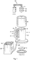
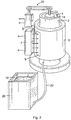
- the tissue infiltration apparatus as shown in figures 1 and 2 comprises a reaction vessel 1 that can be generally of any shape but is preferably, as in this particular embodiment, designed as a regular cylinder having a side wall 2 and a bottom 3.
- the bottom 3 may be made of a material that is transparent for microwaves, or the material may be opaque as to microwaves, depending on whether any additional microwave or other heat generating irradiation like infrared irradiation is intended penetrating of the bottom in axial direction of the reaction vessel 1.
- the side wall 2 is provided with a transparent window section 5 that is transparent to microwaves 6 that are schematically depicted by arrows. These microwaves can be generated and irradiated by the microwave system 7 and penetrate through the transparent window section 5 into the reaction chamber 4.
- the transparent window section 5 is rectangular and is typically made from quartz since quartz is transparent with respect to microwaves.
- the reaction vessel 1 is encapsuled either entirely or in part by a cylindrical heating-and-cooling unit 8 that is in heat conductive contact with the side wall 2 of the reaction vessel 1.
- the side wall 2 of the reaction vessel 1 is also made of heat conductive material. This way, the dielectric 19 inside the reaction vessel 1 and contained in the reaction chamber 4 can be heated or cooled so that a predetermined temperature of the dielectric 19 can be achieved and maintained.
- the upper level of the dielectric 19 is denoted with the fluid surface level line 9 that is visible through the quartz window section 5.
- the tissue samples are held in one or more transport baskets 18 that when submerged in the dielectric 19, can be rotated by a drive mechanism 30 via a rotational axle 11.
- the transport baskets are made of microwave transparent material. Any microwave transparent material might be used. Teflon® (polytetrafluoroethylene (PTFE)) exhibiting electronegativity as a microwave transparent material would be particularly suitable as resistant against breaking and heat.
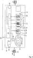
- Figure 3 shows a schematic view of an entire closed tissue infiltration system comprising several reaction vessel 1.
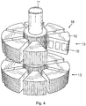
- the tissue samples 21 that are held in the transport basket 18 that is shown in more detail in figure 4 .
- up to sixty samples can be held in one transport basket 18.
- the samples 21 are held in cassettes 10 that are shown in more detail in figure 4 .
- One or more transport baskets 18 are held on the rotational axis axle 11.
- the cassettes 10 are held in several segments 12, and several layers 13 can be held on the rotational axle 11. More details can be gathered from the German Patent Application DE 102007044116 .
- the transport basket is particularly shown in figures 5-7 of publication DE 102007044116 .
- Figure 3 shows schematically that the entire transport basket 18 is submerged into the various dielectrics 19, namely submerged entirely below the various dielectric surface levels 9. The entire system of the embodiment shown in figure 3 is closed as it is symbolized by the schematically shown casing 14.
- a transport mechanism 15 is provided, particularly a transport arm 16 that can grip the various transport baskets 18.
- transport baskets 18 can be held in a carousel 17 and transported one by one into the various dielectric containing reaction vessels 1.
- the dielectric fluids 19 might be custom designed and be pre-filled into the various reaction vessels 1. This allows for more consistent testing results and is another measure for a better control about the required processing time within each one of the dielectrics.
- the transport basket 18 can be inserted into the reaction chamber 4 either manually or automatically by a transport mechanism 15. In this case, it is also possible to insert the transport basket 18 prior to adding the dielectric 19. It is also possible to remove the dielectric 19 through a conduit 22 and replace it by feeding a different dielectric 19 into the same reaction vessel 1.
- the method according to the invention can be used by processing a sample in one single dielectric, i.e. infiltrating only one single dielectric into the tissue sample.
- a "dielectric” refers to any nonmetallic substance, having little or no electrical conductivity, whose charge carriers are not free to move. These materials have electrical or electromagnetic fields applied to them. Upon penetration into a dielectric, microwave radiation results in heating thereof. This occurs due to the absorption of energy. At the same time, an electromagnetic field that reverses direction 2.45 billion times per second occurs.
- aqueous formalin solution as well as a variety of alcohols such as methanol, ethanol, and isopropanol, are dielectrics that are usually utilized in tissue processing with microwave excitation.
- the penetration depth PD depends on the particular dielectric and its temperature. Many materials (e.g. quartz glass) have a very large penetration depth; they are "transparent" to microwave radiation. One rule of thumb states that the hotter the dielectric, the greater its PD.
- ⁇ ' ⁇ " Temp °C
- Quartz glass 3.78 0.0002 25 18937
- a typical sequence of subsequently infiltrated dielectrics is:
- the tissue sample is typically fixed by a fixing agent.
- a fixing agent typically a fluid, is used that has the ability of penetrating the plasma membrane quickly. Since the microwaves make the tissue perform micro-oscillation, the infiltration process is significantly accelerated by irradiating the tissue sample directly with microwaves, for instance accelerated to be 20-fold compared to infiltration as without direct microwave irradiation.
- the formaldehyde or formalin infiltration process typically takes place at the temperature of 20-25 degrees Celsius. Typically, above 25 degrees Celsius, crosslinking of the tissue proteins takes place. Such crosslinking might be desirable. However, prior to crosslinking, proper infiltration has to be completed at a preferred temperature between 20-25 degrees Celsius (68 - 77 degrees Fahrenheit).
- the heating-and-cooling unit 8 can control the temperature to be below 25 degrees Celsius (77 degrees Fahrenheit) during the fixation process involving according to the invention direct microwave irradiation of the tissue samples.
- the tissue sample has to be fully dehydrated.
- a dielectric such as various alcohols is used, for instance isopropanol or ethanol. Isopropanol infiltrates best at a temperature of 60 degrees Celsius (140 degrees Fahrenheit) into the tissue sample, while ethanol infiltrates best into the tissue sample at a somewhat lower temperature, particularly 40 degrees Celsius (104 degrees Fahrenheit).
- the infiltration speed is accelerated, for instance to be quadrupled in comparison with infiltration not irradiating of the tissue samples directly with microwaves. This effect of acceleration the infiltration can be explained by the micro-oscillation of the tissue that is directly exposed to microwave irradiation.
- the heating-and-cooling unit 8 can help heating up the dehydration dielectric to the most favored processing temperature.
- Some dielectrics fulfill both functions of dehydration and providing an appropriate intermedium for paraffin infiltration, for instance isopropanol. It is also possible to provide a mixture of dielectrics comprising an intermedium. However, other dehydration dielectrics such as ethanol are not appropriate intermediums. Again, for infiltrating in intermedium into the tissue sample, infiltration is accelerated by irradiating of the tissue sample directly with microwaves.
- Figure 3 resembles a closed system comprising a plurality of reaction vessels 1.
- the reaction vessel 1A comprises formaldehyde as a dielectric for performing of the fixation step
- reaction vessel 1B comprises isopropanol for performing both the step of dehydration and infiltration with an intermedium
- reaction vessel 1C comprises paraffin as a dielectric for performing the step of paraffinizing.
- An input station accordingly is embodied in the form of the carousel 17 and serves simultaneously as a storage unit and as means for definable modification of the order of multiple transport baskets 18.
- the carousel 17 comprises six individual receiving positions into each of which a transport basket 4 can be placed.
- An operator transfers one or more of the transport basket 18 into the carousel 17.
- the transport arm 16 can remove the transport basket 18 from the carousel 17.
- a transport basket 18 transferred to carousel 17 can be stored therein by the fact that carousel 17 rotates a different receiving position to the input or output position.
- a transport basket 18 When a transport basket 18 is to be placed, it is transported into the respective position of carousel 17.
- the three transport baskets 18 that are shown are located in reaction vessels 1A, 1B, 1C.
- transport basket 18 present in reaction vessel 1A is delivered by transport arm 16 into an output position of the carousel 17.
- the carousel 17 is then rotated one position to the right, so that transport basket 18 requiring processing next is delivered to output position.
- a transport arm 16 then delivers transport basket 18 into reaction vessel 1A.
- the transport baskets present in reaction vessels 1A, 1B and 1C are then each moved one position further in execution sequence fixation, dehydration/intermedium and paraffinizing and the transport basket 18 that is still in carousel 17 can be delivered either back into reaction vessel 1A or, as soon as it is unoccupied, into reaction vessel 1B.
- transport basket 18 requiring urgent processing can be brought one position ahead of the other transport basket 18 in execution sequence, so that the order of transport baskets 18 has been modified.
- the cassettes 10 and/or a transport basket 18 respectively comprise(s) an identifying means.
- the identifying means makes possible identification of the cassettes and/or of the transport basket.
- the identifying means could be a barcode or a machine-readable imprint or a transponder or radio frequency identification (RFID) tag.
- RFID radio frequency identification
- the remaining treatment time of a cassette or of a transport basket could also be ascertainable on the basis of the identifying means. This feature can be helpful if a specimen or cassette must be accessed at an earlier time than expected, in which case the specimen can be processed manually.
- the order of the transport baskets could be ascertainable, and optionally modifiable, as a function of the identification of the cassettes and/or the transport basket.
- information could also be provided regarding the type of processing of the specimens in the tissue infiltration apparatus, which information either is stored in suitable fashion in the identifying means or is transmitted, for example, via a network to the tissue infiltration apparatus, if identification of the respective cassette or transport basket is performed.
- a reading device with which the identifying means of the cassettes or the transport basket can respectively be read, would need to be provided for this purpose in the tissue infiltration apparatus. This information could be conveyed to a control unit 23 of the tissue infiltration apparatus.
- the control unit 23 could be configured in such a way that as a function of the information ascertained for the cassettes 10 or the particular transport basket 18, the execution sequence of the individual transport baskets (and thus of the cassettes) through the reaction vessels 1A, 1B and 1C of the tissue infiltration apparatus is managed in variable fashion, or in a manner optimized for a definable processing goal.
- One such processing goal could be a shortest possible processing time for the cassettes in the tissue infiltration apparatus.
- a further processing goal could be a special execution sequence for a specific type of specimen.
- the identifying means embodied in the form of a transponder 24, is provided on each transport basket 18.
- Information can additionally be stored in transponder 24 about the processing steps with which the samples are to be, or have been, processed.
- Information concerning prioritization of the processing of the individual specimens present in transport basket 18, or about transport baskets 18, can also be stored in transponder 24.
- the information stored in transponder 24 can be read out in non-contact fashion with reading unit 25, and transmitted to control unit 23.
- Control unit 23 can then, as a function of the information read out from transponder 24 of a transport basket 18, plan and correspondingly carry out the processing steps for that transport basket 18.
- Located in the vicinity of output station 3 is a writing unit 26 with which information about the individual processing steps that a transport basket 18 has passed through in tissue infiltration apparatus 1 can be written into transponder 24.
- reaction vessel 1A, 1B, 1C it is also conceivable for at least one reaction vessel 1A, 1B, 1C to be fillable automatically with a different dielectric fluid. This could take place, in particular, at a definable or adjustable time.
- the reaction vessel for dehydration could, in particular, be respectively filled with an alcohol-containing dielectric fluid having a different alcohol concentration.
- filling of the reaction vessel with a different dielectric fluid could be possible in operator initiated fashion manually.
- dielectric fluid 19 of reaction vessel 1B serving for dehydration can be exchanged, for which purpose an exchange apparatus 27 is provided.
- the latter comprises pumps and valves (not illustrated), and is connected by means of two conduit connections to reaction vessel 1B.
- energy is applicable to the contents of at least one reaction vessel, in particular for a definable period of time.
- the energy is, in particular, thermal energy or electromagnetic waves, for example microwaves and/or ultrasonic waves.
- the contents of the reaction vessel to which heat or energy is to be applied could include the dielectric fluid, a transport basket present therein, and/or cassettes present therein. It is particularly useful to apply energy to the reaction vessel that is provided for wax/paraffin treatment, since this operation is thereby accelerated.
- reaction vessel 1C Provided on reaction vessel 1C is a heating unit 29, embodied in the form of an irradiating device irradiation infrared irradiation or microwave irradiation, with which dielectric fluid 19 in reaction vessel 1C can be heated.
- a heating unit 29 embodied in the form of an irradiating device irradiation infrared irradiation or microwave irradiation, with which dielectric fluid 19 in reaction vessel 1C can be heated.
- the direct irradiation comes from the window section 5 in the reaction vessels side wall so that controlled and uniform irradiating of all samples can be maintained throughout the process.
- Providing additional irradiation just to heat up the paraffin brings the temperature of the paraffin faster to the optimum infiltration temperature so that in combination with a combined direct irradiation of the samples as describe above accelerates infiltration.
- priority criteria on the basis of which the order of the transport baskets is ascertainable, are inputtable and/or ascertainable.
- the priority criteria could be inputted, for example, by an operator. It is additionally conceivable that the priority criteria are transmitted to the tissue infiltration apparatus via a network or a database system. This could be useful in particular if the tissue infiltration apparatus is incorporated into a laboratory control system. It is very generally conceivable that the order of two transport baskets is definably modifiable under the control of the laboratory control system in remote controlled fashion. Control could also be applied to further preparation devices with a laboratory control system of this kind, so that ideally, almost entirely automated specimen preparation is possible. This kind of incorporation of the tissue infiltration apparatus or its control device could be achieved by linkage to a control computer for the laboratory control system via a network, or to a database system.
- Tissue infiltration apparatus can be incorporated, via network connection 28, into a laboratory control system (not shown in the figures) that comprises a control computer and is linked to a database system in which patient data, among other information, is stored.
- a laboratory control system (not shown in the figures) that comprises a control computer and is linked to a database system in which patient data, among other information, is stored.
Landscapes
- Health & Medical Sciences (AREA)
- Life Sciences & Earth Sciences (AREA)
- General Health & Medical Sciences (AREA)
- Physics & Mathematics (AREA)
- Chemical & Material Sciences (AREA)
- Analytical Chemistry (AREA)
- Biochemistry (AREA)
- General Physics & Mathematics (AREA)
- Immunology (AREA)
- Pathology (AREA)
- Biomedical Technology (AREA)
- Molecular Biology (AREA)
- Engineering & Computer Science (AREA)
- Sampling And Sample Adjustment (AREA)
Applications Claiming Priority (2)
| Application Number | Priority Date | Filing Date | Title |
|---|---|---|---|
| US12/543,226 US20110045565A1 (en) | 2009-08-18 | 2009-08-18 | Apparatus and method for accelerated tissue infiltration by means of microwave excitation |
| PCT/EP2010/004892 WO2011020574A1 (en) | 2009-08-18 | 2010-08-11 | Apparatus and method for accelerated tissue infiltration by means of microwave excitation |
Publications (2)
| Publication Number | Publication Date |
|---|---|
| EP2467695A1 EP2467695A1 (en) | 2012-06-27 |
| EP2467695B1 true EP2467695B1 (en) | 2018-07-25 |
Family
ID=43242458
Family Applications (1)
| Application Number | Title | Priority Date | Filing Date |
|---|---|---|---|
| EP10744886.2A Not-in-force EP2467695B1 (en) | 2009-08-18 | 2010-08-11 | Apparatus and method for accelerated tissue infiltration by means of microwave excitation |
Country Status (5)
| Country | Link |
|---|---|
| US (1) | US20110045565A1 (enExample) |
| EP (1) | EP2467695B1 (enExample) |
| JP (1) | JP5530521B2 (enExample) |
| CN (1) | CN102483371B (enExample) |
| WO (1) | WO2011020574A1 (enExample) |
Families Citing this family (9)
| Publication number | Priority date | Publication date | Assignee | Title |
|---|---|---|---|---|
| GB201100152D0 (en) * | 2011-01-06 | 2011-02-23 | Epistem Ltd | Genedrive RFID |
| US10201331B2 (en) | 2012-06-22 | 2019-02-12 | Leica Biosystems Nussloch Gmbh | Biopsy tissue sample transport device and method of using thereof |
| JP6487320B2 (ja) | 2012-06-22 | 2019-03-20 | ライカ ビオズュステムス ヌスロッホ ゲーエムベーハー | 組織サンプル容器及び方法 |
| US9097629B2 (en) | 2013-03-15 | 2015-08-04 | Leica Biosystems Nussloch Gmbh | Tissue cassette with retractable member |
| US9052256B2 (en) | 2013-03-15 | 2015-06-09 | Leica Biosystems Nussloch Gmbh | Method for processing and embedding tissue |
| CA2845832C (en) | 2013-03-15 | 2020-09-22 | Leica Biosystems Nussloch Gmbh | Tissue cassette with biasing element |
| WO2018119194A1 (en) | 2016-12-22 | 2018-06-28 | Ventana Medical Systems, Inc. | System and method for sample processing |
| CN110799843B (zh) * | 2017-08-22 | 2023-08-22 | 莱卡生物系统墨尔本私人有限公司 | 监测待由组织处理器处理的组织样本的系统和方法 |
| JP7014460B1 (ja) | 2020-09-30 | 2022-02-01 | 株式会社常光 | パラフィン包埋ブロック作製装置 |
Family Cites Families (16)
| Publication number | Priority date | Publication date | Assignee | Title |
|---|---|---|---|---|
| US3462575A (en) * | 1967-05-31 | 1969-08-19 | Holaday Ind Inc | Microwave heating device |
| US4891239A (en) * | 1988-07-05 | 1990-01-02 | Raytheon Company | Method and apparatus for ultrafast microwave tissue fixation |
| US5068086A (en) * | 1990-06-12 | 1991-11-26 | Raytheon Company | Method and apparatus for batch fixating tissue specimens |
| US5532462A (en) * | 1994-04-29 | 1996-07-02 | Communications & Power Industries | Method of and apparatus for heating a reaction vessel with microwave energy |
| US5796080A (en) * | 1995-10-03 | 1998-08-18 | Cem Corporation | Microwave apparatus for controlling power levels in individual multiple cells |
| ES2119535T3 (es) * | 1996-08-02 | 1998-10-01 | Milestone Srl | Procedimiento para procesar muestras organicas. |
| JPH1167443A (ja) * | 1997-08-14 | 1999-03-09 | Fumiaki Okada | マイクロ波集束用レンズ状誘電体装荷アプリケータ |
| JP2001004506A (ja) * | 1999-06-24 | 2001-01-12 | Shichiro Miyazawa | 電子顕微鏡試料作製装置及び電子顕微鏡試料作製方法 |
| JP2003517601A (ja) * | 1999-12-14 | 2003-05-27 | ユニバーシティー・オブ・マイアミ | 迅速な組織処理器 |
| US6875583B2 (en) * | 2001-05-22 | 2005-04-05 | Ted Pella, Inc. | Rapid microwave-assisted fixation of fresh tissue |
| DE602004018112D1 (de) * | 2004-06-07 | 2009-01-15 | Milestone Srl | Verfahren und Vorrichtung zur mikrowellen-unterstützten automatischen Gewebebehandlung |
| US9017964B2 (en) * | 2005-08-26 | 2015-04-28 | Denator Aktiebolag | Preparing biological samples for analysis |
| GB0620061D0 (en) * | 2006-10-10 | 2006-11-22 | Medical Device Innovations Ltd | Oesophageal treatment apparatus and method |
| DE102007008713B4 (de) * | 2007-02-20 | 2019-07-11 | Leica Biosystems Nussloch Gmbh | Gewebeinfiltrationsvorrichtung |
| JP5016984B2 (ja) * | 2007-06-06 | 2012-09-05 | 四国計測工業株式会社 | マイクロ波化学反応装置および方法 |
| DE202007013921U1 (de) * | 2007-09-16 | 2007-12-27 | Leica Biosystems Nussloch Gmbh | Gewebeinfiltrationsvorrichtung |
-
2009
- 2009-08-18 US US12/543,226 patent/US20110045565A1/en not_active Abandoned
-
2010
- 2010-08-11 CN CN201080037051.1A patent/CN102483371B/zh not_active Expired - Fee Related
- 2010-08-11 EP EP10744886.2A patent/EP2467695B1/en not_active Not-in-force
- 2010-08-11 WO PCT/EP2010/004892 patent/WO2011020574A1/en not_active Ceased
- 2010-08-11 JP JP2012525075A patent/JP5530521B2/ja active Active
Non-Patent Citations (1)
| Title |
|---|
| None * |
Also Published As
| Publication number | Publication date |
|---|---|
| US20110045565A1 (en) | 2011-02-24 |
| WO2011020574A1 (en) | 2011-02-24 |
| CN102483371A (zh) | 2012-05-30 |
| EP2467695A1 (en) | 2012-06-27 |
| CN102483371B (zh) | 2015-03-25 |
| JP2013502560A (ja) | 2013-01-24 |
| JP5530521B2 (ja) | 2014-06-25 |
Similar Documents
| Publication | Publication Date | Title |
|---|---|---|
| EP2467695B1 (en) | Apparatus and method for accelerated tissue infiltration by means of microwave excitation | |
| JP2013502560A5 (enExample) | ||
| AU773429B2 (en) | Rapid tissue processor | |
| US6793890B2 (en) | Rapid tissue processor | |
| CA2849908C (en) | Ultra-rapid diagnostic tissue preparation as an alternative to frozen section | |
| EP1676117B1 (en) | Simplified tissue processing | |
| EP3824266A2 (en) | Automated slide processing systems, consumable slide processing modules, and reagent cartridges | |
| Webster | Microwave-assisted processing and embedding for transmission electron microscopy | |
| Shruthi et al. | Use of microwave in diagnostic pathology | |
| WO2018100017A1 (en) | Method and system for treating biological samples | |
| WO2013116207A2 (en) | Slide pocket | |
| US8530808B2 (en) | Microwave-assisted heating and processing techniques | |
| Sathyakumar et al. | Tissue processing of oral biopsy specimens: An adjunct to diagnosis | |
| CN116507899A (zh) | 可变功率冷微波组织处理器 | |
| Austin | Basic procedure for electron microscopy processing and staining in clinical laboratory using microwave oven | |
| Shah | Comparative Study of Tissue Processing and Staining by Microwave and Routine Method | |
| AU2015227390A1 (en) | Ultra-rapid diagnostic tissue preparation as an alternative to frozen section | |
| Selvamani et al. | Microwave Histotechnology Vs Conventional Histotechnology: A Review | |
| Bozzola | Cytochem. 27/4 Methods of microwave fixation for microscopy. A review of research and clinical applications: 1970–1992, GR Login, AM Dvorak, 127 pages, Progress Histochem, W. Graumann, Z. Lojda, AGE Pearse, TH Schiebler (Eds.), Gustav Fischer Verlag (1994) |
Legal Events
| Date | Code | Title | Description |
|---|---|---|---|
| PUAI | Public reference made under article 153(3) epc to a published international application that has entered the european phase |
Free format text: ORIGINAL CODE: 0009012 |
|
| 17P | Request for examination filed |
Effective date: 20120217 |
|
| AK | Designated contracting states |
Kind code of ref document: A1 Designated state(s): AL AT BE BG CH CY CZ DE DK EE ES FI FR GB GR HR HU IE IS IT LI LT LU LV MC MK MT NL NO PL PT RO SE SI SK SM TR |
|
| RIN1 | Information on inventor provided before grant (corrected) |
Inventor name: SANDERS, MARK Inventor name: ULBRICH, HERMANN |
|
| DAX | Request for extension of the european patent (deleted) | ||
| 17Q | First examination report despatched |
Effective date: 20171110 |
|
| GRAP | Despatch of communication of intention to grant a patent |
Free format text: ORIGINAL CODE: EPIDOSNIGR1 |
|
| INTG | Intention to grant announced |
Effective date: 20180301 |
|
| GRAS | Grant fee paid |
Free format text: ORIGINAL CODE: EPIDOSNIGR3 |
|
| GRAA | (expected) grant |
Free format text: ORIGINAL CODE: 0009210 |
|
| AK | Designated contracting states |
Kind code of ref document: B1 Designated state(s): AL AT BE BG CH CY CZ DE DK EE ES FI FR GB GR HR HU IE IS IT LI LT LU LV MC MK MT NL NO PL PT RO SE SI SK SM TR |
|
| REG | Reference to a national code |
Ref country code: GB Ref legal event code: FG4D |
|
| REG | Reference to a national code |
Ref country code: CH Ref legal event code: EP |
|
| REG | Reference to a national code |
Ref country code: AT Ref legal event code: REF Ref document number: 1022280 Country of ref document: AT Kind code of ref document: T Effective date: 20180815 |
|
| REG | Reference to a national code |
Ref country code: DE Ref legal event code: R096 Ref document number: 602010052169 Country of ref document: DE |
|
| REG | Reference to a national code |
Ref country code: IE Ref legal event code: FG4D |
|
| REG | Reference to a national code |
Ref country code: FR Ref legal event code: PLFP Year of fee payment: 9 |
|
| REG | Reference to a national code |
Ref country code: NL Ref legal event code: MP Effective date: 20180725 |
|
| REG | Reference to a national code |
Ref country code: LT Ref legal event code: MG4D |
|
| PG25 | Lapsed in a contracting state [announced via postgrant information from national office to epo] |
Ref country code: NL Free format text: LAPSE BECAUSE OF FAILURE TO SUBMIT A TRANSLATION OF THE DESCRIPTION OR TO PAY THE FEE WITHIN THE PRESCRIBED TIME-LIMIT Effective date: 20180725 |
|
| REG | Reference to a national code |
Ref country code: AT Ref legal event code: MK05 Ref document number: 1022280 Country of ref document: AT Kind code of ref document: T Effective date: 20180725 |
|
| PG25 | Lapsed in a contracting state [announced via postgrant information from national office to epo] |
Ref country code: BG Free format text: LAPSE BECAUSE OF FAILURE TO SUBMIT A TRANSLATION OF THE DESCRIPTION OR TO PAY THE FEE WITHIN THE PRESCRIBED TIME-LIMIT Effective date: 20181025 Ref country code: LT Free format text: LAPSE BECAUSE OF FAILURE TO SUBMIT A TRANSLATION OF THE DESCRIPTION OR TO PAY THE FEE WITHIN THE PRESCRIBED TIME-LIMIT Effective date: 20180725 Ref country code: AT Free format text: LAPSE BECAUSE OF FAILURE TO SUBMIT A TRANSLATION OF THE DESCRIPTION OR TO PAY THE FEE WITHIN THE PRESCRIBED TIME-LIMIT Effective date: 20180725 Ref country code: IS Free format text: LAPSE BECAUSE OF FAILURE TO SUBMIT A TRANSLATION OF THE DESCRIPTION OR TO PAY THE FEE WITHIN THE PRESCRIBED TIME-LIMIT Effective date: 20181125 Ref country code: PL Free format text: LAPSE BECAUSE OF FAILURE TO SUBMIT A TRANSLATION OF THE DESCRIPTION OR TO PAY THE FEE WITHIN THE PRESCRIBED TIME-LIMIT Effective date: 20180725 Ref country code: NO Free format text: LAPSE BECAUSE OF FAILURE TO SUBMIT A TRANSLATION OF THE DESCRIPTION OR TO PAY THE FEE WITHIN THE PRESCRIBED TIME-LIMIT Effective date: 20181025 Ref country code: FI Free format text: LAPSE BECAUSE OF FAILURE TO SUBMIT A TRANSLATION OF THE DESCRIPTION OR TO PAY THE FEE WITHIN THE PRESCRIBED TIME-LIMIT Effective date: 20180725 Ref country code: GR Free format text: LAPSE BECAUSE OF FAILURE TO SUBMIT A TRANSLATION OF THE DESCRIPTION OR TO PAY THE FEE WITHIN THE PRESCRIBED TIME-LIMIT Effective date: 20181026 Ref country code: SE Free format text: LAPSE BECAUSE OF FAILURE TO SUBMIT A TRANSLATION OF THE DESCRIPTION OR TO PAY THE FEE WITHIN THE PRESCRIBED TIME-LIMIT Effective date: 20180725 |
|
| PG25 | Lapsed in a contracting state [announced via postgrant information from national office to epo] |
Ref country code: HR Free format text: LAPSE BECAUSE OF FAILURE TO SUBMIT A TRANSLATION OF THE DESCRIPTION OR TO PAY THE FEE WITHIN THE PRESCRIBED TIME-LIMIT Effective date: 20180725 Ref country code: ES Free format text: LAPSE BECAUSE OF FAILURE TO SUBMIT A TRANSLATION OF THE DESCRIPTION OR TO PAY THE FEE WITHIN THE PRESCRIBED TIME-LIMIT Effective date: 20180725 Ref country code: AL Free format text: LAPSE BECAUSE OF FAILURE TO SUBMIT A TRANSLATION OF THE DESCRIPTION OR TO PAY THE FEE WITHIN THE PRESCRIBED TIME-LIMIT Effective date: 20180725 Ref country code: LV Free format text: LAPSE BECAUSE OF FAILURE TO SUBMIT A TRANSLATION OF THE DESCRIPTION OR TO PAY THE FEE WITHIN THE PRESCRIBED TIME-LIMIT Effective date: 20180725 |
|
| REG | Reference to a national code |
Ref country code: CH Ref legal event code: PL |
|
| REG | Reference to a national code |
Ref country code: DE Ref legal event code: R097 Ref document number: 602010052169 Country of ref document: DE |
|
| PG25 | Lapsed in a contracting state [announced via postgrant information from national office to epo] |
Ref country code: EE Free format text: LAPSE BECAUSE OF FAILURE TO SUBMIT A TRANSLATION OF THE DESCRIPTION OR TO PAY THE FEE WITHIN THE PRESCRIBED TIME-LIMIT Effective date: 20180725 Ref country code: MC Free format text: LAPSE BECAUSE OF FAILURE TO SUBMIT A TRANSLATION OF THE DESCRIPTION OR TO PAY THE FEE WITHIN THE PRESCRIBED TIME-LIMIT Effective date: 20180725 Ref country code: LU Free format text: LAPSE BECAUSE OF NON-PAYMENT OF DUE FEES Effective date: 20180811 Ref country code: LI Free format text: LAPSE BECAUSE OF NON-PAYMENT OF DUE FEES Effective date: 20180831 Ref country code: IT Free format text: LAPSE BECAUSE OF FAILURE TO SUBMIT A TRANSLATION OF THE DESCRIPTION OR TO PAY THE FEE WITHIN THE PRESCRIBED TIME-LIMIT Effective date: 20180725 Ref country code: CH Free format text: LAPSE BECAUSE OF NON-PAYMENT OF DUE FEES Effective date: 20180831 Ref country code: RO Free format text: LAPSE BECAUSE OF FAILURE TO SUBMIT A TRANSLATION OF THE DESCRIPTION OR TO PAY THE FEE WITHIN THE PRESCRIBED TIME-LIMIT Effective date: 20180725 Ref country code: CZ Free format text: LAPSE BECAUSE OF FAILURE TO SUBMIT A TRANSLATION OF THE DESCRIPTION OR TO PAY THE FEE WITHIN THE PRESCRIBED TIME-LIMIT Effective date: 20180725 |
|
| REG | Reference to a national code |
Ref country code: BE Ref legal event code: MM Effective date: 20180831 |
|
| REG | Reference to a national code |
Ref country code: IE Ref legal event code: MM4A |
|
| PG25 | Lapsed in a contracting state [announced via postgrant information from national office to epo] |
Ref country code: SM Free format text: LAPSE BECAUSE OF FAILURE TO SUBMIT A TRANSLATION OF THE DESCRIPTION OR TO PAY THE FEE WITHIN THE PRESCRIBED TIME-LIMIT Effective date: 20180725 Ref country code: DK Free format text: LAPSE BECAUSE OF FAILURE TO SUBMIT A TRANSLATION OF THE DESCRIPTION OR TO PAY THE FEE WITHIN THE PRESCRIBED TIME-LIMIT Effective date: 20180725 Ref country code: SK Free format text: LAPSE BECAUSE OF FAILURE TO SUBMIT A TRANSLATION OF THE DESCRIPTION OR TO PAY THE FEE WITHIN THE PRESCRIBED TIME-LIMIT Effective date: 20180725 |
|
| PLBE | No opposition filed within time limit |
Free format text: ORIGINAL CODE: 0009261 |
|
| STAA | Information on the status of an ep patent application or granted ep patent |
Free format text: STATUS: NO OPPOSITION FILED WITHIN TIME LIMIT |
|
| 26N | No opposition filed |
Effective date: 20190426 |
|
| PG25 | Lapsed in a contracting state [announced via postgrant information from national office to epo] |
Ref country code: IE Free format text: LAPSE BECAUSE OF NON-PAYMENT OF DUE FEES Effective date: 20180811 |
|
| PG25 | Lapsed in a contracting state [announced via postgrant information from national office to epo] |
Ref country code: BE Free format text: LAPSE BECAUSE OF NON-PAYMENT OF DUE FEES Effective date: 20180831 Ref country code: SI Free format text: LAPSE BECAUSE OF FAILURE TO SUBMIT A TRANSLATION OF THE DESCRIPTION OR TO PAY THE FEE WITHIN THE PRESCRIBED TIME-LIMIT Effective date: 20180725 |
|
| PG25 | Lapsed in a contracting state [announced via postgrant information from national office to epo] |
Ref country code: MT Free format text: LAPSE BECAUSE OF NON-PAYMENT OF DUE FEES Effective date: 20180811 |
|
| PG25 | Lapsed in a contracting state [announced via postgrant information from national office to epo] |
Ref country code: TR Free format text: LAPSE BECAUSE OF FAILURE TO SUBMIT A TRANSLATION OF THE DESCRIPTION OR TO PAY THE FEE WITHIN THE PRESCRIBED TIME-LIMIT Effective date: 20180725 |
|
| PG25 | Lapsed in a contracting state [announced via postgrant information from national office to epo] |
Ref country code: HU Free format text: LAPSE BECAUSE OF FAILURE TO SUBMIT A TRANSLATION OF THE DESCRIPTION OR TO PAY THE FEE WITHIN THE PRESCRIBED TIME-LIMIT; INVALID AB INITIO Effective date: 20100811 Ref country code: PT Free format text: LAPSE BECAUSE OF FAILURE TO SUBMIT A TRANSLATION OF THE DESCRIPTION OR TO PAY THE FEE WITHIN THE PRESCRIBED TIME-LIMIT Effective date: 20180725 |
|
| PG25 | Lapsed in a contracting state [announced via postgrant information from national office to epo] |
Ref country code: CY Free format text: LAPSE BECAUSE OF FAILURE TO SUBMIT A TRANSLATION OF THE DESCRIPTION OR TO PAY THE FEE WITHIN THE PRESCRIBED TIME-LIMIT Effective date: 20180725 Ref country code: MK Free format text: LAPSE BECAUSE OF NON-PAYMENT OF DUE FEES Effective date: 20180725 |
|
| P01 | Opt-out of the competence of the unified patent court (upc) registered |
Effective date: 20230525 |
|
| PGFP | Annual fee paid to national office [announced via postgrant information from national office to epo] |
Ref country code: FR Payment date: 20230620 Year of fee payment: 14 |
|
| PGFP | Annual fee paid to national office [announced via postgrant information from national office to epo] |
Ref country code: GB Payment date: 20230622 Year of fee payment: 14 |
|
| PGFP | Annual fee paid to national office [announced via postgrant information from national office to epo] |
Ref country code: DE Payment date: 20230613 Year of fee payment: 14 |
|
| REG | Reference to a national code |
Ref country code: DE Ref legal event code: R119 Ref document number: 602010052169 Country of ref document: DE |
|
| GBPC | Gb: european patent ceased through non-payment of renewal fee |
Effective date: 20240811 |
|
| PG25 | Lapsed in a contracting state [announced via postgrant information from national office to epo] |
Ref country code: DE Free format text: LAPSE BECAUSE OF NON-PAYMENT OF DUE FEES Effective date: 20250301 |
|
| PG25 | Lapsed in a contracting state [announced via postgrant information from national office to epo] |
Ref country code: GB Free format text: LAPSE BECAUSE OF NON-PAYMENT OF DUE FEES Effective date: 20240811 |
|
| PG25 | Lapsed in a contracting state [announced via postgrant information from national office to epo] |
Ref country code: FR Free format text: LAPSE BECAUSE OF NON-PAYMENT OF DUE FEES Effective date: 20240831 |