EP2467682B1 - Messanordnung für eine flüssigkeit, insbesondere zur verwendung in einer milchannahmeanordnung, und verfahren zum betrieb einer milchannahmeanordnung - Google Patents
Messanordnung für eine flüssigkeit, insbesondere zur verwendung in einer milchannahmeanordnung, und verfahren zum betrieb einer milchannahmeanordnung Download PDFInfo
- Publication number
- EP2467682B1 EP2467682B1 EP10798265.4A EP10798265A EP2467682B1 EP 2467682 B1 EP2467682 B1 EP 2467682B1 EP 10798265 A EP10798265 A EP 10798265A EP 2467682 B1 EP2467682 B1 EP 2467682B1
- Authority
- EP
- European Patent Office
- Prior art keywords
- measuring
- tube
- arrangement
- electrodes
- liquid
- Prior art date
- Legal status (The legal status is an assumption and is not a legal conclusion. Google has not performed a legal analysis and makes no representation as to the accuracy of the status listed.)
- Active
Links
Images


Classifications
-
- G—PHYSICS
- G01—MEASURING; TESTING
- G01F—MEASURING VOLUME, VOLUME FLOW, MASS FLOW OR LIQUID LEVEL; METERING BY VOLUME
- G01F15/00—Details of, or accessories for, apparatus of groups G01F1/00 - G01F13/00 insofar as such details or appliances are not adapted to particular types of such apparatus
- G01F15/10—Preventing damage by freezing or excess pressure or insufficient pressure
-
- A—HUMAN NECESSITIES
- A01—AGRICULTURE; FORESTRY; ANIMAL HUSBANDRY; HUNTING; TRAPPING; FISHING
- A01J—MANUFACTURE OF DAIRY PRODUCTS
- A01J5/00—Milking machines or devices
- A01J5/007—Monitoring milking processes; Control or regulation of milking machines
- A01J5/01—Milkmeters; Milk flow sensing devices
-
- G—PHYSICS
- G01—MEASURING; TESTING
- G01F—MEASURING VOLUME, VOLUME FLOW, MASS FLOW OR LIQUID LEVEL; METERING BY VOLUME
- G01F23/00—Indicating or measuring liquid level or level of fluent solid material, e.g. indicating in terms of volume or indicating by means of an alarm
- G01F23/22—Indicating or measuring liquid level or level of fluent solid material, e.g. indicating in terms of volume or indicating by means of an alarm by measuring physical variables, other than linear dimensions, pressure or weight, dependent on the level to be measured, e.g. by difference of heat transfer of steam or water
- G01F23/24—Indicating or measuring liquid level or level of fluent solid material, e.g. indicating in terms of volume or indicating by means of an alarm by measuring physical variables, other than linear dimensions, pressure or weight, dependent on the level to be measured, e.g. by difference of heat transfer of steam or water by measuring variations of resistance of resistors due to contact with conductor fluid
- G01F23/241—Indicating or measuring liquid level or level of fluent solid material, e.g. indicating in terms of volume or indicating by means of an alarm by measuring physical variables, other than linear dimensions, pressure or weight, dependent on the level to be measured, e.g. by difference of heat transfer of steam or water by measuring variations of resistance of resistors due to contact with conductor fluid for discrete levels
- G01F23/242—Mounting arrangements for electrodes
-
- G—PHYSICS
- G01—MEASURING; TESTING
- G01N—INVESTIGATING OR ANALYSING MATERIALS BY DETERMINING THEIR CHEMICAL OR PHYSICAL PROPERTIES
- G01N27/00—Investigating or analysing materials by the use of electric, electrochemical, or magnetic means
- G01N27/02—Investigating or analysing materials by the use of electric, electrochemical, or magnetic means by investigating impedance
- G01N27/04—Investigating or analysing materials by the use of electric, electrochemical, or magnetic means by investigating impedance by investigating resistance
- G01N27/06—Investigating or analysing materials by the use of electric, electrochemical, or magnetic means by investigating impedance by investigating resistance of a liquid
- G01N27/08—Investigating or analysing materials by the use of electric, electrochemical, or magnetic means by investigating impedance by investigating resistance of a liquid which is flowing continuously
-
- G—PHYSICS
- G01—MEASURING; TESTING
- G01N—INVESTIGATING OR ANALYSING MATERIALS BY DETERMINING THEIR CHEMICAL OR PHYSICAL PROPERTIES
- G01N33/00—Investigating or analysing materials by specific methods not covered by groups G01N1/00 - G01N31/00
- G01N33/02—Food
- G01N33/04—Dairy products
-
- F—MECHANICAL ENGINEERING; LIGHTING; HEATING; WEAPONS; BLASTING
- F04—POSITIVE - DISPLACEMENT MACHINES FOR LIQUIDS; PUMPS FOR LIQUIDS OR ELASTIC FLUIDS
- F04C—ROTARY-PISTON, OR OSCILLATING-PISTON, POSITIVE-DISPLACEMENT MACHINES FOR LIQUIDS; ROTARY-PISTON, OR OSCILLATING-PISTON, POSITIVE-DISPLACEMENT PUMPS
- F04C2220/00—Application
- F04C2220/24—Application for metering throughflow
Definitions
- the invention relates to a measuring arrangement for a liquid, in particular for use in a liquid receiving arrangement, preferably milk receiving arrangement, according to the preamble of claim 1.
- a measuring arrangement is formed with a measuring tube for passing the liquid and two elongated electrodes, at least partially opposite each other in the measuring tube are arranged.
- the invention further relates to the use of such a measuring arrangement in a liquid receiving arrangement and to a method for operating a liquid receiving arrangement.
- milk bins In dairy farming, large quantities of milk are transported daily from individual producers (farmers, farmers) to processors (dairies, food factories). This transport is almost exclusively done by milk collection trucks.
- Such milk bins have one or more collection tanks, as well as a milk receiving assembly for transferring the milk into the tank and determining the transferred amount of liquid.
- the known milk receiving arrangement has a measuring section with a flow measuring device and a gas proportion measuring device, wherein the gas proportion measuring device can also be referred to as a filling degree measuring device.
- the gas proportion measuring device can also be referred to as a filling degree measuring device.
- a storage container which is arranged in a side arm of the delivery line, and allows a calming and degassing of highly gas-penetrated amounts of liquid.
- Embodiments of filling degree measuring devices or gas proportion measuring devices for use in a milk receiving arrangement proceed from the closest one WO 2006/063631 A1 out.
- the degree of filling / gas content is determined by a conductivity measurement.
- electrodes are provided in a measuring tube, which are surrounded by insulating wall areas to avoid measuring errors.
- Milk intake arrangements such as in the WO 2008/141664 A1 described have a pickup pump. This serves to create a negative pressure to suck the milk and then to transport them with positive pressure in the collection tank.
- Different acceptance conditions can be encountered in the milk acceptance, namely an arrangement of the dispenser tank of the producer, a level arrangement of the dispensing tank or an underground arrangement of the dispensing tank, which is increased compared with the pump and / or the collection tank of the milk collection vehicle.
- the pumping power in practice may be limited by the occurrence of cavitation.
- Cavitation that is the local evaporation due to local negative pressure, is a well-known phenomenon and, for example, in the DE 2 452 641 A described.
- vitation is usually already avoidable because it has the potential to damage the milk. Therefore, the pump should aim for an operating state in which the pumping capacity is so high that cavitation is barely avoided.
- Kavitationsproblematik teaches the WO 2008/141664 A1 Accordingly, to regulate the suction pressure of the pump to a value at which cavitation of the liquid is prevented.
- cavitation sensors For the detection of cavitation in different situations cavitation sensors are known. So is according to the DE 24 52 641 A a cavitation sensor on an acoustic basis for a watercraft known.
- the DE 699 37 747 T2 The idea is to use acoustic emissions, optical scattering, high-speed photography, mechanical damage or sonochemicals to detect cavitation.
- an accelerometer or an acoustic transducer is used as the cavitation sensor.
- DE 197 25 012 C1 The propagation properties of Rayleigh waves are used to detect cavitation.
- the DE 197 15 480 A1 teaches the use of an acoustic cavitation sensor.
- the DE 100 45 847 A1 teaches a cavitation sensor with a piezoelectric element.
- a measuring arrangement for determining the flow rate of milk in a mixture of milk and air with means for separating the air is known. Furthermore, an open measuring chamber is described in which measuring electrodes are arranged. The degree of filling of the measuring chamber is determined by means of measuring electrodes and converted into a flow value.
- the milk collection device has two electrodes, which extend in the longitudinal direction of the measuring device substantially parallel to each other.
- the object of the invention is to provide a measuring arrangement, in particular for a milk receiving arrangement, and method for operating such arrangements, which ensure a particularly large variety of applications and a particularly high efficiency.
- the measuring arrangement according to the invention is characterized in that the measurement arrangement for measuring cavitation can be filled with the liquid, wherein the occurrence of cavitation is detected by a change in the conductivity between the two electrodes due to cavitation without and the measuring arrangement is flowed through in a conveying operation by the liquid, in the vertical direction.
- a measuring arrangement which allows a conductivity measurement of the liquid flowing through. Due to their special electrode arrangement, one and the same measuring arrangement can be used for at least three different functions. Thus, by conductivity measurement between the electrodes on the one hand, the degree of filling, that is, the liquid or gas content in the liquid can be determined. The degree of filling determined in this case can be used to correct the measurement results of a flow measuring device with regard to gas fractions.
- the measuring arrangement acts as a cavitation sensor. For if cavitation occurs in the liquid, cavitation bubbles cause a change in the conductivity between the two electrodes. If this effect is detected, then the conveying speed, the suction pressure and / or the power of a feed pump can be reduced accordingly, so that the cavitation is prevented again.
- the measuring arrangement according to the invention can also be used as a level sensor in order to determine, for example after completion of the transfer, the fill level in a delivery line course.
- the electrodes are at least approximately perpendicular and thus perpendicular to the liquid surface, which defines the filling level at the conclusion of the transfer. Due to this vertical arrangement, a filling level change results in a significant change in the conductivity value between the electrodes, so that a particularly representative signal for the filling level can be obtained by conductivity measurement.
- the simultaneously provided according to the invention vertical pipe course has, moreover, in particular with constant pipe cross-section in the region of the electrodes result in a mathematically particularly simple relationship between the measured conductivity value and the filling level, which greatly simplifies the evaluation.
- the longitudinal axis and / or the symmetry axis of the measuring tube can be understood as the tube axis.
- the course of the electrodes according to the invention along the tube axis can be understood in particular to mean that the longitudinal axes of the electrodes (that is to say those axes of the electrodes which correspond to the direction of the largest electrode extent) run parallel to the tube axis.
- this idea may include that the electrode extension in the direction of the tube axis is greater than transverse to the tube axis, in particular by at least a factor of 2 or 5 larger.
- the invention thus includes that the electrodes extend in the direction of flow of the liquid, which is the vertical in the region of the electrodes.
- the electrodes can have at least one rectangular contact surface for the liquid, in which case according to the invention the longer rectangle side runs parallel to the tube axis of the measuring tube.
- the electrodes can also be designed, for example, rod-shaped, in which case the longitudinal or symmetry axis of the rod can run parallel to the tube axis.
- the measuring tube expediently has an inlet opening and an outlet opening, so that the liquid to be characterized can be passed through the measuring tube.
- Connections in particular flange elements, are suitably provided in the region of these openings, so that the measuring tube can be installed in a delivery line course of an acceptance arrangement.
- the measuring tube may, for example, have a round, in particular circular, a rectangular or a square inner cross section. If an angular cross-section is provided in the region of the electrodes, it is advantageous for the measuring tube to have a round inner cross-section in the region of the openings and / or connections, so that a fluidically favorable transition to the line system is provided.
- the measuring tube has, for example, a hollow-cylindrical tube wall. This tube wall can define a measuring chamber in the interior of the tube through which the liquid flows and with which the electrodes are in contact.
- the tube wall has an electrical insulator material at least on the inner side of the tube.
- the pipe wall is formed on its contact surface with the liquid to be measured non-conductive, which may be advantageous in terms of measurement accuracy.
- the pipe wall can also consist entirely of the insulator material.
- the insulator material may in particular be a plastic material.
- the electrodes are suitably designed for electrical contact with the liquid which means they are at least partially carried out in the interior of the measuring tube with an electrically conductive surface.
- a particularly robust embodiment is given according to the invention in that the electrodes abut against the tube wall of the measuring tube.
- recesses may be provided in the tube wall for the electrodes, in which the electrodes are accommodated.
- the electrodes can also be spaced from the tube wall of the measuring tube. Such an embodiment also allows a particularly simple replacement of the electrodes.
- a further advantageous embodiment of the invention is that spacers are provided on the pipe wall, which protrude into the interior of the measuring tube, and on which the electrodes are mounted.
- the spacers may be cylindrical, for example.
- the longitudinal axes of the spacers extend transversely, in particular radially, to the tube axis.
- the spacer can be mounted particularly easily, for example by fastening means such as nuts or other on the tube outside. If a spacer penetrates the pipe wall, a seal is expediently arranged thereon in order to prevent leakage of liquid from the interior of the pipe in the region of the spacer. Preferably, all spacers can penetrate the pipe wall.
- a further preferred embodiment of the invention is that at least one of the spacers comprises an electrical insulator material.
- the electrical insulator material may in particular be a plastic material. It may be sufficient that the spacer has the electrical insulator material on its surface.
- the spacer may also be made solid from the electrical insulator material. Preferably, all spacers on an electrical insulator material.
- a further advantageous embodiment of the invention is that at least one of the spacers, for. B. in its interior, a connecting line for electrical contact with the content Erten electrode.
- the spacer serves not only for fixing the electrode but also for electrically contacting the electrode.
- each electrode is associated with at least one spacer, which has such a connecting line.
- a particularly simple and at the same time reliable mounting of the electrodes can be ensured by holding at least one of the electrodes on at least two support points on the measuring tube.
- the holder is preferably carried out via the aforementioned spacers.
- the support locations may be provided in particular in two opposite end regions of the electrode. It is particularly preferred that the holder of the electrode is carried on at least one of the support points via a floating bearing.
- the floating bearing allows for thermal expansion and / or thermal contraction of the electrode. Such a floating bearing thus prevents thermal stresses due to different expansion coefficients of electrode and measuring tube wall.
- a metallic electrode may not expand as much as an insulating tube wall.
- the floating bearing can be formed for example as a bore in the spacer.
- a fixed bearing is preferably provided, which may be formed for example by a blind hole in the spacer. Conveniently, both electrodes are supported as described.
- the electrodes are used for a conductivity measurement.
- a conductivity measuring device is provided, which is in line connection with the electrodes for measuring the conductivity between the two electrodes.
- the conductivity measuring device can have, for example, a voltage source and a current measuring device.
- a pump is provided for conveying the liquid.
- the measuring arrangement can directly fulfill the three aforementioned functions cavitation measurement, filling degree measurement and level measurement.
- the measuring tube is arranged linewise between a storage container for the liquid and the pump, and / or that the measuring tube is arranged according to the conduit between an inlet for the liquid and the pump.
- a storage container can be provided, for example, for the degassing of the liquid and be arranged at a branch of the delivery line.
- An inlet may be understood to mean a feed opening for the liquid, which may be formed, for example, on a hose and / or a proboscis.
- the invention also relates to the use of the measuring arrangement according to the invention in a liquid receiving arrangement, in particular a milk receiving arrangement.
- a liquid receiving arrangement in particular a milk receiving arrangement.
- Such an acceptance arrangement preferably has a delivery line which on the one hand has an inlet for the liquid and on the other hand a connection for a collecting tank, and preferably also a pump and / or a flow measuring device.
- a computing device may be provided which is in signal communication with the fill-flow correction of the results of the flow measurement both with the flow measuring device and with the measuring arrangement according to the invention, in particular with their electrodes and / or their conductivity measuring device.
- the measuring arrangement is used for cavitation measurement, for filling degree measurement and for level determination. This corresponds to the triple functionality of the measuring arrangement described above.
- the invention also relates to a method for operating a liquid receiving arrangement, in particular milk receiving arrangement, wherein the conductivity of the conveyed liquid is measured with a measuring arrangement according to the invention, and the power of a pump provided in the liquid receiving arrangement is reduced when cavitation is detected by means of the measuring arrangement. Accordingly, the suction pressure is reduced when Cavitation is detected. This makes it possible to regulate the pump performance so that cavitation is barely avoided, so that maximum throughput is achieved without damaging the milk.
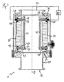
- FIGS. 1 to 3 A first exemplary embodiment of a measuring arrangement 1 according to the invention is shown in FIGS. 1 to 3 shown.
- the measuring arrangement 1 has a measuring tube 10, in which two electrodes 20, 20 'are arranged diametrically opposite one another.
- the measuring tube 10 has a tube wall 11, which is formed at the level of the electrodes 20 insulating.
- the electrode 20 is elongate and has a rectangular contact surface with the tube interior and with the liquid to be measured.
- the electrode 20 is arranged according to the invention so that its longitudinal axis is parallel to the tube axis 3 of the measuring tube 10, that is, that the elongate electrode 20 extends along the tube axis 3.
- the second electrode 20 ' is designed analogously to the first electrode 20.
- the measuring tube 10 is shown in its operating position, in which the measuring tube 10 and thus its tube axis 3 are perpendicular.
- the measuring tube 10 can serve according to the invention in a particularly simple manner for level determination.
- the measuring tube 10 can be traversed by the liquid to be measured in the direction of arrow A.
- the tube wall 11 of the measuring tube 10 is made of an insulating material, such as plastic.
- the electrodes 20, 20 lie directly against the tube wall 11 of the measuring tube 10.
- the measuring tube 10 in the region of the electrodes 20 has a rectangular, in particular square, tube cross-section, in particular in FIG FIG. 3 is recognizable.
- the measuring tube 10 has connections 14, 15, on which flange-type connecting devices are provided.
- the measuring tube has a circular inner cross-section for a particularly streamlined connection to conventional pipelines.
- FIGS. 4 and 5 A further embodiment of a measuring arrangement 1 according to the invention is shown in FIGS FIGS. 4 and 5 shown.
- a measuring tube 30 with an insulating tube wall 31 is also provided, on which two electrodes 40 and 40 'are arranged.
- the electrodes 40, 40 'rod-shaped with, for example, round, in particular circular cross-section, and spaced from the pipe wall 31 executed.
- spacers 42, 42', 43, 43 ' are provided on the tube wall 31. Of these spacers 42, 42 ', 43, 43', only the spacers 42 and 43 of the first electrode 40 will be described below.
- the spacers 42 and 43 are bolt-shaped and arranged so that their longitudinal axes extend radially to the tube axis 3.
- the bolt-shaped spacers 42, 43 penetrate the pipe wall 31 and are secured on the outside of the pipe wall 31 via screw nuts 44 and 45 on the pipe wall 31.
- the upper spacer 42 has a parallel to the tube axis 3 extending blind hole 55, which receives the rod-shaped electrode 40 and forms an axially fixed bearing for the electrode 40.
- the opposite lower spacer 43 has a through hole 54, which forms a movable bearing 51 for the electrode 40. This floating bearing 51 allows axial movement of the electrode 40 relative to the spacer 43. Different thermal expansions between the metallic electrode 40 and the existing plastic pipe wall 31 thus do not lead to thermal stress.
- the upper spacer 42 On the outside of the tube, the upper spacer 42 has an electrical contact 49.
- This contact 49 is conductively connected to the electrode 40 with a connecting line, not shown in the figures for clarity, which runs in the interior of the spacer 42.
- spacers 42 and 43 are disposed at the ends of the electrode 40. However, they can be placed anywhere along the electrode 40.
- a conductivity measuring device 80 is provided.
- This conductivity measuring device 80 serves to measure the conductivity of the liquid between the electrodes 40, 40 '.
- the conductivity measuring device 80 is connected via the respective contacts 49, 49 'to the electrodes 40 and 40'.
- the measuring tube 30 is formed both at the level of the electrodes 40, 40 'and in the region of the terminals 34, 35 with a circular inner cross-section.
- the measuring tube 30 has flange regions 36 and 37, respectively, which serve for connection to a pipeline system.
- the measuring tube 30 preferably be formed metallic.
- clamp seals 38 between flange areas 36 and 37 on the one hand and the pipe wall 31 on the other hand In order to be able to compensate for different temperature-dependent expansions of flange areas 36, 37 and plastic pipe wall 31, clamp seals 38 between flange areas 36 and 37 on the one hand and the pipe wall 31 on the other hand. 39 arranged.
- FIG. 6 shows a liquid receiving arrangement in which an inventive ⁇ e measuring arrangement 1 can be used.
- a milk receiving arrangement 70 has a delivery line 79, which on the one hand has an inlet 73 for liquid, in particular milk, and which, on the other hand, is connected to a collection tank 7, which is shown only schematically.
- a pump 71 for conveying the liquid is arranged in the course of the delivery line 79.
- a storage container 72 is provided in a side arm of the delivery line 79, which can serve to calm the liquid at the beginning and / or end of acceptance.
- a milk sensor 76, a pressure sensor 77 and a flow measuring device 78 are arranged.
- the milk sensor 76 and the pressure sensor 77 are arranged between the inlet 73 and the pump 71.
- the flow meter 78 is disposed between the pump 71 and the tank 7.
- the measuring arrangement 1 is provided on the suction side of the pump 71, that is to say on the side of the pump 71 which is in line connection with the inlet 73.
- the measuring arrangement 1 is connected directly upstream of the pump 71.
- the milk receiving arrangement 70 with the measuring arrangement 1 according to the invention can be operated as follows:
- the delivery line 79 and thus the measuring arrangement 1 are filled and the conductivity of the milk is determined by means of the measuring arrangement 1 when the product is at a standstill or at a slow conveying speed. Then, the delivery rate, for example by increasing the performance of the pump 71, increased until the desired negative pressure is established, which can be determined by means of the pressure sensor 77. The conductance is continuously controlled with the measuring arrangement 1. If the delivery rate is to be brought up to the cavitation limit, then the suction negative pressure is increased by increasing the pumping power until the conductance measured by the measuring arrangement 1 decreases. This decrease in conductivity is due to the smallest gas bubbles that form due to cavitation. The detection of the cavitation by means of the measuring arrangement 1 makes it possible to regulate the pumping power in such a way that the pump 71 is currently working at the cavitation boundary.
- the measured values of the flow measuring device 78 can be corrected with the filling degree measured values of the measuring arrangement 1.
- the measuring arrangement 1 can serve as a level sensor.
- the milk is pumped out of the storage container 72, wherein the fill level in the delivery line 79 must, as a rule, be driven to a defined closure level in order to be able to precisely determine the acceptance volume. Because a difference between start level and stop level causes a volume difference, which must be taken into account.
- the measuring arrangement 1 can also be used for this process step since it emits a fill level-dependent signal and thus allows it to end at the end of acceptance to reach a predetermined level and / or to demonstrate differences in level between the start of acceptance and the end of acceptance.
Landscapes
- Physics & Mathematics (AREA)
- Life Sciences & Earth Sciences (AREA)
- General Physics & Mathematics (AREA)
- Chemical & Material Sciences (AREA)
- Health & Medical Sciences (AREA)
- Biochemistry (AREA)
- Pathology (AREA)
- Engineering & Computer Science (AREA)
- Food Science & Technology (AREA)
- Analytical Chemistry (AREA)
- Fluid Mechanics (AREA)
- General Health & Medical Sciences (AREA)
- Immunology (AREA)
- Chemical Kinetics & Catalysis (AREA)
- Medicinal Chemistry (AREA)
- Electrochemistry (AREA)
- Animal Husbandry (AREA)
- Environmental Sciences (AREA)
- Thermal Sciences (AREA)
- Investigating Or Analyzing Materials By The Use Of Electric Means (AREA)
- Sampling And Sample Adjustment (AREA)
- Dairy Products (AREA)
Priority Applications (1)
| Application Number | Priority Date | Filing Date | Title |
|---|---|---|---|
| PL10798265T PL2467682T3 (pl) | 2009-12-18 | 2010-12-17 | Układ pomiarowy dla cieczy, w szczególności do zastosowania w układzie odbierającym mleko, oraz sposób pracy układu odbierającego mleko |
Applications Claiming Priority (2)
| Application Number | Priority Date | Filing Date | Title |
|---|---|---|---|
| DE102009058838A DE102009058838A1 (de) | 2009-12-18 | 2009-12-18 | Messanordnung für eine Flüssigkeit, insbesondere zur Verwendung in einer Milchannahmeanordnung, und Verfahren zum Betrieb einer Milchannahmeanordnung |
| PCT/EP2010/007760 WO2011072874A2 (de) | 2009-12-18 | 2010-12-17 | Messanordnung für eine flüssigkeit, insbesondere zur verwendung in einer milchannahmeanordnung, und verfahren zum betrieb einer milchannahmeanordnung |
Publications (2)
| Publication Number | Publication Date |
|---|---|
| EP2467682A2 EP2467682A2 (de) | 2012-06-27 |
| EP2467682B1 true EP2467682B1 (de) | 2013-07-31 |
Family
ID=44022097
Family Applications (1)
| Application Number | Title | Priority Date | Filing Date |
|---|---|---|---|
| EP10798265.4A Active EP2467682B1 (de) | 2009-12-18 | 2010-12-17 | Messanordnung für eine flüssigkeit, insbesondere zur verwendung in einer milchannahmeanordnung, und verfahren zum betrieb einer milchannahmeanordnung |
Country Status (4)
| Country | Link |
|---|---|
| EP (1) | EP2467682B1 (pl) |
| DE (1) | DE102009058838A1 (pl) |
| PL (1) | PL2467682T3 (pl) |
| WO (1) | WO2011072874A2 (pl) |
Families Citing this family (1)
| Publication number | Priority date | Publication date | Assignee | Title |
|---|---|---|---|---|
| CN103674132B (zh) * | 2013-12-25 | 2016-06-08 | 栾川龙宇钼业有限公司 | 一种非满流管道出口流量测量装置及方法 |
Family Cites Families (13)
| Publication number | Priority date | Publication date | Assignee | Title |
|---|---|---|---|---|
| US3910216A (en) | 1974-06-10 | 1975-10-07 | Boeing Co | Hydrofoil cavitation sensing and control apparatus |
| US5251148A (en) | 1990-06-01 | 1993-10-05 | Valtek, Inc. | Integrated process control valve |
| NL1000471C1 (nl) * | 1995-03-24 | 1996-09-26 | Maasland Nv | Hoeveelheidsmeter en inrichting voor het melken van dieren, voorzien van een dergelijke meter. |
| DE19715480C2 (de) | 1997-04-14 | 1999-01-14 | Saskia Solar Und Energietechni | Vakuumpumpsystem mit einer Flüssigringpumpe |
| DE19725012C1 (de) | 1997-06-13 | 1998-11-05 | Brose Fahrzeugteile | Verfahren zum Messen physikalischer oder technischer Größen von Flüssigkeiten, einschließlich hochviskoser teigiger oder pastöser Medien, unter Verwendung eines akustischen Übertragungssystems mit wenigstens einer von einer Festkörperoberfläche gebildeten Meßstrecke sowie Vorrichtung zur Durchführung des Verfahrens |
| ATE381016T1 (de) | 1998-10-28 | 2007-12-15 | Covaris Inc | Vorrichtung und verfahren zur kontrolle einer akustischen behandlung |
| GB9921982D0 (en) | 1999-09-16 | 1999-11-17 | Secretary Trade Ind Brit | Cavitation sensor |
| DE10233312A1 (de) * | 2002-07-22 | 2004-03-04 | Westfaliasurge Gmbh | Verfahren und Vorrichtung zur Bestimmung eines Volumenstroms während eines Melkvorgangs einer fließenden Milch |
| DE102005005295A1 (de) * | 2004-12-16 | 2006-06-22 | Bartec Gmbh | Verfahren zur Förderung und zur Fördermengenerfassung einer Flüssigkeit und Vorrichtung zur Mengenerfassung bei der Annahme und/oder Abgabe einer Flüssigkeit |
| DE202004019442U1 (de) | 2004-12-16 | 2005-03-10 | Bartec Gmbh | Vorrichtung zum Bestimmen des Füllgrades eines Fluides |
| EP1906726B1 (en) * | 2005-07-08 | 2019-08-21 | Aktieselskabet S.A. Christensen & Co. | A measuring device for milk flow |
| DE102006014207A1 (de) * | 2006-03-25 | 2007-09-27 | Westfaliasurge Gmbh | Milchsammeleinrichtung und Verfahren zum Betreiben einer Milchsammeleinrichtung |
| PL2148563T3 (pl) | 2007-05-22 | 2012-01-31 | Bartec Benke Gmbh | Sposób i urządzenie do określania ilości podczas transferu płynu |
-
2009
- 2009-12-18 DE DE102009058838A patent/DE102009058838A1/de not_active Withdrawn
-
2010
- 2010-12-17 PL PL10798265T patent/PL2467682T3/pl unknown
- 2010-12-17 WO PCT/EP2010/007760 patent/WO2011072874A2/de not_active Ceased
- 2010-12-17 EP EP10798265.4A patent/EP2467682B1/de active Active
Also Published As
| Publication number | Publication date |
|---|---|
| WO2011072874A3 (de) | 2011-09-09 |
| DE102009058838A1 (de) | 2011-06-22 |
| PL2467682T3 (pl) | 2014-05-30 |
| EP2467682A2 (de) | 2012-06-27 |
| WO2011072874A2 (de) | 2011-06-23 |
Similar Documents
| Publication | Publication Date | Title |
|---|---|---|
| EP2095085B1 (de) | Adapter für drucksensoren | |
| EP2739944B1 (de) | Verfahren zum detektieren einer belagsbildung oder einer abrasion in einem durchflussmessgerät | |
| DE102009027581B4 (de) | Messvorrichtung umfassend eine Messsonde und eine Befestigungsvorrichtung | |
| WO2000012972A1 (de) | Vorrichtung und verfahren zur volumenbestimmung | |
| DE102015122542A1 (de) | Feldgerät der Prozessmesstechnik | |
| DE102010001993A1 (de) | Magnetisch-induktives Durchflussmessgerät | |
| WO2018104236A1 (de) | Füllstandssensor | |
| EP2467682B1 (de) | Messanordnung für eine flüssigkeit, insbesondere zur verwendung in einer milchannahmeanordnung, und verfahren zum betrieb einer milchannahmeanordnung | |
| EP1597554B1 (de) | Verfahren zur feststellung wenigstens eines zustandsparameters eines dichtungssystems sowie dichtungssystem | |
| DE102009036633B4 (de) | Messvorrichtung | |
| EP1764587A2 (de) | Magnetisch-induktiver Durchflussmesser mit einer Erdungsscheibe | |
| EP2947443B1 (de) | Manometeranordnung | |
| DE102010008066B3 (de) | Buchholzrelais | |
| DE102011084906A1 (de) | Verfahren zur Überwachung einer Pumpe für Flüssigkeiten und Pumpe | |
| DE102005005295A1 (de) | Verfahren zur Förderung und zur Fördermengenerfassung einer Flüssigkeit und Vorrichtung zur Mengenerfassung bei der Annahme und/oder Abgabe einer Flüssigkeit | |
| EP2990777B1 (de) | Vorrichtung und verfahren zur erfassung von eigenschaften oder des füllstands eines mediums in einem behälter | |
| EP2199754B1 (de) | Verfahren und Vorrichtung zur Übergabe einer zumindest zeitweise einen Gaseinschluss aufweisenden Flüssigkeit und zur Bestimmung der übergebenen Flüssigkeitsmenge | |
| DE102014102054A1 (de) | Füllstandsensor mit Elektrodenüberwachung | |
| DE3902107A1 (de) | Kapazitive fuellstands- und niveaumesseinrichtung | |
| DE102010035965A1 (de) | Druckmessumformer | |
| DE102011079927A1 (de) | Verfahren zur Bestimmung eines Dosiervolumens eines automatischen Peristaltik-Probenehmers | |
| DE102015011665A1 (de) | Verfahren und System zum Bestimmen des Füllstands eines elektrisch leitfähigen Mediums in zumindest einem Behälter | |
| EP1339978A1 (de) | Vorrichtung und verfahren zum messen der einspritzmenge von einspritzdüsen, insbesonderer für kraftfahrzeuge | |
| EP1582848A1 (de) | Verfahren und Vorrichtung zur Prüfung von Typ und Qualität eines flüssigen Mediums in einem Tank | |
| DE102020104868B3 (de) | Kraftstoffleitung und Fahrzeugzustandsüberwachungssystem |
Legal Events
| Date | Code | Title | Description |
|---|---|---|---|
| PUAI | Public reference made under article 153(3) epc to a published international application that has entered the european phase |
Free format text: ORIGINAL CODE: 0009012 |
|
| 17P | Request for examination filed |
Effective date: 20120302 |
|
| AK | Designated contracting states |
Kind code of ref document: A2 Designated state(s): AL AT BE BG CH CY CZ DE DK EE ES FI FR GB GR HR HU IE IS IT LI LT LU LV MC MK MT NL NO PL PT RO RS SE SI SK SM TR |
|
| GRAP | Despatch of communication of intention to grant a patent |
Free format text: ORIGINAL CODE: EPIDOSNIGR1 |
|
| DAX | Request for extension of the european patent (deleted) | ||
| GRAS | Grant fee paid |
Free format text: ORIGINAL CODE: EPIDOSNIGR3 |
|
| GRAA | (expected) grant |
Free format text: ORIGINAL CODE: 0009210 |
|
| AK | Designated contracting states |
Kind code of ref document: B1 Designated state(s): AL AT BE BG CH CY CZ DE DK EE ES FI FR GB GR HR HU IE IS IT LI LT LU LV MC MK MT NL NO PL PT RO RS SE SI SK SM TR |
|
| REG | Reference to a national code |
Ref country code: GB Ref legal event code: FG4D Free format text: NOT ENGLISH Ref country code: CH Ref legal event code: EP |
|
| REG | Reference to a national code |
Ref country code: AT Ref legal event code: REF Ref document number: 624913 Country of ref document: AT Kind code of ref document: T Effective date: 20130815 |
|
| REG | Reference to a national code |
Ref country code: IE Ref legal event code: FG4D Free format text: LANGUAGE OF EP DOCUMENT: GERMAN |
|
| REG | Reference to a national code |
Ref country code: DE Ref legal event code: R096 Ref document number: 502010004252 Country of ref document: DE Effective date: 20130926 |
|
| GRAT | Correction requested after decision to grant or after decision to maintain patent in amended form |
Free format text: ORIGINAL CODE: EPIDOSNCDEC |
|
| REG | Reference to a national code |
Ref country code: CH Ref legal event code: NV Representative=s name: TROESCH SCHEIDEGGER WERNER AG, CH |
|
| REG | Reference to a national code |
Ref country code: NL Ref legal event code: T3 |
|
| RAP2 | Party data changed (patent owner data changed or rights of a patent transferred) |
Owner name: BARTEC BENKE GMBH |
|
| REG | Reference to a national code |
Ref country code: LT Ref legal event code: MG4D |
|
| PG25 | Lapsed in a contracting state [announced via postgrant information from national office to epo] |
Ref country code: PT Free format text: LAPSE BECAUSE OF FAILURE TO SUBMIT A TRANSLATION OF THE DESCRIPTION OR TO PAY THE FEE WITHIN THE PRESCRIBED TIME-LIMIT Effective date: 20131202 Ref country code: HR Free format text: LAPSE BECAUSE OF FAILURE TO SUBMIT A TRANSLATION OF THE DESCRIPTION OR TO PAY THE FEE WITHIN THE PRESCRIBED TIME-LIMIT Effective date: 20130731 Ref country code: SE Free format text: LAPSE BECAUSE OF FAILURE TO SUBMIT A TRANSLATION OF THE DESCRIPTION OR TO PAY THE FEE WITHIN THE PRESCRIBED TIME-LIMIT Effective date: 20130731 Ref country code: CY Free format text: LAPSE BECAUSE OF FAILURE TO SUBMIT A TRANSLATION OF THE DESCRIPTION OR TO PAY THE FEE WITHIN THE PRESCRIBED TIME-LIMIT Effective date: 20130828 Ref country code: NO Free format text: LAPSE BECAUSE OF FAILURE TO SUBMIT A TRANSLATION OF THE DESCRIPTION OR TO PAY THE FEE WITHIN THE PRESCRIBED TIME-LIMIT Effective date: 20131031 Ref country code: LT Free format text: LAPSE BECAUSE OF FAILURE TO SUBMIT A TRANSLATION OF THE DESCRIPTION OR TO PAY THE FEE WITHIN THE PRESCRIBED TIME-LIMIT Effective date: 20130731 Ref country code: IS Free format text: LAPSE BECAUSE OF FAILURE TO SUBMIT A TRANSLATION OF THE DESCRIPTION OR TO PAY THE FEE WITHIN THE PRESCRIBED TIME-LIMIT Effective date: 20131130 |
|
| REG | Reference to a national code |
Ref country code: CH Ref legal event code: NV Representative=s name: PATENTANWALTSBUERO JEAN HUNZIKER AG, CH Ref country code: CH Ref legal event code: PCOW Free format text: NEW ADDRESS: BORSIGSTRASSE 10, 21465 REINBEK/HAMBURG (DE) |
|
| PG25 | Lapsed in a contracting state [announced via postgrant information from national office to epo] |
Ref country code: LV Free format text: LAPSE BECAUSE OF FAILURE TO SUBMIT A TRANSLATION OF THE DESCRIPTION OR TO PAY THE FEE WITHIN THE PRESCRIBED TIME-LIMIT Effective date: 20130731 Ref country code: SI Free format text: LAPSE BECAUSE OF FAILURE TO SUBMIT A TRANSLATION OF THE DESCRIPTION OR TO PAY THE FEE WITHIN THE PRESCRIBED TIME-LIMIT Effective date: 20130731 Ref country code: GR Free format text: LAPSE BECAUSE OF FAILURE TO SUBMIT A TRANSLATION OF THE DESCRIPTION OR TO PAY THE FEE WITHIN THE PRESCRIBED TIME-LIMIT Effective date: 20131101 Ref country code: FI Free format text: LAPSE BECAUSE OF FAILURE TO SUBMIT A TRANSLATION OF THE DESCRIPTION OR TO PAY THE FEE WITHIN THE PRESCRIBED TIME-LIMIT Effective date: 20130731 |
|
| PG25 | Lapsed in a contracting state [announced via postgrant information from national office to epo] |
Ref country code: CY Free format text: LAPSE BECAUSE OF FAILURE TO SUBMIT A TRANSLATION OF THE DESCRIPTION OR TO PAY THE FEE WITHIN THE PRESCRIBED TIME-LIMIT Effective date: 20130731 |
|
| PG25 | Lapsed in a contracting state [announced via postgrant information from national office to epo] |
Ref country code: DK Free format text: LAPSE BECAUSE OF FAILURE TO SUBMIT A TRANSLATION OF THE DESCRIPTION OR TO PAY THE FEE WITHIN THE PRESCRIBED TIME-LIMIT Effective date: 20130731 Ref country code: CZ Free format text: LAPSE BECAUSE OF FAILURE TO SUBMIT A TRANSLATION OF THE DESCRIPTION OR TO PAY THE FEE WITHIN THE PRESCRIBED TIME-LIMIT Effective date: 20130731 Ref country code: EE Free format text: LAPSE BECAUSE OF FAILURE TO SUBMIT A TRANSLATION OF THE DESCRIPTION OR TO PAY THE FEE WITHIN THE PRESCRIBED TIME-LIMIT Effective date: 20130731 Ref country code: RO Free format text: LAPSE BECAUSE OF FAILURE TO SUBMIT A TRANSLATION OF THE DESCRIPTION OR TO PAY THE FEE WITHIN THE PRESCRIBED TIME-LIMIT Effective date: 20130731 Ref country code: SK Free format text: LAPSE BECAUSE OF FAILURE TO SUBMIT A TRANSLATION OF THE DESCRIPTION OR TO PAY THE FEE WITHIN THE PRESCRIBED TIME-LIMIT Effective date: 20130731 |
|
| PG25 | Lapsed in a contracting state [announced via postgrant information from national office to epo] |
Ref country code: IT Free format text: LAPSE BECAUSE OF FAILURE TO SUBMIT A TRANSLATION OF THE DESCRIPTION OR TO PAY THE FEE WITHIN THE PRESCRIBED TIME-LIMIT Effective date: 20130731 Ref country code: ES Free format text: LAPSE BECAUSE OF FAILURE TO SUBMIT A TRANSLATION OF THE DESCRIPTION OR TO PAY THE FEE WITHIN THE PRESCRIBED TIME-LIMIT Effective date: 20130731 |
|
| REG | Reference to a national code |
Ref country code: PL Ref legal event code: T3 |
|
| PLBE | No opposition filed within time limit |
Free format text: ORIGINAL CODE: 0009261 |
|
| STAA | Information on the status of an ep patent application or granted ep patent |
Free format text: STATUS: NO OPPOSITION FILED WITHIN TIME LIMIT |
|
| 26N | No opposition filed |
Effective date: 20140502 |
|
| REG | Reference to a national code |
Ref country code: DE Ref legal event code: R097 Ref document number: 502010004252 Country of ref document: DE Effective date: 20140502 |
|
| PG25 | Lapsed in a contracting state [announced via postgrant information from national office to epo] |
Ref country code: LU Free format text: LAPSE BECAUSE OF FAILURE TO SUBMIT A TRANSLATION OF THE DESCRIPTION OR TO PAY THE FEE WITHIN THE PRESCRIBED TIME-LIMIT Effective date: 20131217 |
|
| REG | Reference to a national code |
Ref country code: IE Ref legal event code: MM4A |
|
| REG | Reference to a national code |
Ref country code: FR Ref legal event code: ST Effective date: 20140829 |
|
| PG25 | Lapsed in a contracting state [announced via postgrant information from national office to epo] |
Ref country code: IE Free format text: LAPSE BECAUSE OF NON-PAYMENT OF DUE FEES Effective date: 20131217 |
|
| PG25 | Lapsed in a contracting state [announced via postgrant information from national office to epo] |
Ref country code: FR Free format text: LAPSE BECAUSE OF NON-PAYMENT OF DUE FEES Effective date: 20131231 |
|
| PG25 | Lapsed in a contracting state [announced via postgrant information from national office to epo] |
Ref country code: MC Free format text: LAPSE BECAUSE OF FAILURE TO SUBMIT A TRANSLATION OF THE DESCRIPTION OR TO PAY THE FEE WITHIN THE PRESCRIBED TIME-LIMIT Effective date: 20130731 |
|
| PG25 | Lapsed in a contracting state [announced via postgrant information from national office to epo] |
Ref country code: SM Free format text: LAPSE BECAUSE OF FAILURE TO SUBMIT A TRANSLATION OF THE DESCRIPTION OR TO PAY THE FEE WITHIN THE PRESCRIBED TIME-LIMIT Effective date: 20130731 |
|
| PG25 | Lapsed in a contracting state [announced via postgrant information from national office to epo] |
Ref country code: TR Free format text: LAPSE BECAUSE OF FAILURE TO SUBMIT A TRANSLATION OF THE DESCRIPTION OR TO PAY THE FEE WITHIN THE PRESCRIBED TIME-LIMIT Effective date: 20130731 |
|
| PG25 | Lapsed in a contracting state [announced via postgrant information from national office to epo] |
Ref country code: HU Free format text: LAPSE BECAUSE OF FAILURE TO SUBMIT A TRANSLATION OF THE DESCRIPTION OR TO PAY THE FEE WITHIN THE PRESCRIBED TIME-LIMIT; INVALID AB INITIO Effective date: 20101217 Ref country code: RS Free format text: LAPSE BECAUSE OF FAILURE TO SUBMIT A TRANSLATION OF THE DESCRIPTION OR TO PAY THE FEE WITHIN THE PRESCRIBED TIME-LIMIT Effective date: 20131031 Ref country code: BG Free format text: LAPSE BECAUSE OF FAILURE TO SUBMIT A TRANSLATION OF THE DESCRIPTION OR TO PAY THE FEE WITHIN THE PRESCRIBED TIME-LIMIT Effective date: 20130731 Ref country code: MK Free format text: LAPSE BECAUSE OF FAILURE TO SUBMIT A TRANSLATION OF THE DESCRIPTION OR TO PAY THE FEE WITHIN THE PRESCRIBED TIME-LIMIT Effective date: 20130731 |
|
| GBPC | Gb: european patent ceased through non-payment of renewal fee |
Effective date: 20141217 |
|
| PG25 | Lapsed in a contracting state [announced via postgrant information from national office to epo] |
Ref country code: MT Free format text: LAPSE BECAUSE OF FAILURE TO SUBMIT A TRANSLATION OF THE DESCRIPTION OR TO PAY THE FEE WITHIN THE PRESCRIBED TIME-LIMIT Effective date: 20130731 |
|
| PG25 | Lapsed in a contracting state [announced via postgrant information from national office to epo] |
Ref country code: GB Free format text: LAPSE BECAUSE OF NON-PAYMENT OF DUE FEES Effective date: 20141217 |
|
| PG25 | Lapsed in a contracting state [announced via postgrant information from national office to epo] |
Ref country code: AL Free format text: LAPSE BECAUSE OF FAILURE TO SUBMIT A TRANSLATION OF THE DESCRIPTION OR TO PAY THE FEE WITHIN THE PRESCRIBED TIME-LIMIT Effective date: 20130731 |
|
| REG | Reference to a national code |
Ref country code: CH Ref legal event code: PFUS Owner name: BARTEC BENKE GMBH, DE Free format text: FORMER OWNER: BARTEC BENKE GMBH, DE |
|
| P01 | Opt-out of the competence of the unified patent court (upc) registered |
Effective date: 20230726 |
|
| PGFP | Annual fee paid to national office [announced via postgrant information from national office to epo] |
Ref country code: DE Payment date: 20250226 Year of fee payment: 15 |
|
| PGFP | Annual fee paid to national office [announced via postgrant information from national office to epo] |
Ref country code: CH Payment date: 20250101 Year of fee payment: 15 |
|
| REG | Reference to a national code |
Ref country code: CH Ref legal event code: U11 Free format text: ST27 STATUS EVENT CODE: U-0-0-U10-U11 (AS PROVIDED BY THE NATIONAL OFFICE) Effective date: 20260101 |
|
| PGFP | Annual fee paid to national office [announced via postgrant information from national office to epo] |
Ref country code: AT Payment date: 20251217 Year of fee payment: 16 |
|
| PGFP | Annual fee paid to national office [announced via postgrant information from national office to epo] |
Ref country code: NL Payment date: 20251223 Year of fee payment: 16 |
|
| PGFP | Annual fee paid to national office [announced via postgrant information from national office to epo] |
Ref country code: BE Payment date: 20251229 Year of fee payment: 16 |
|
| PGFP | Annual fee paid to national office [announced via postgrant information from national office to epo] |
Ref country code: PL Payment date: 20251215 Year of fee payment: 16 |