EP2467682B1 - Measurement device for a liquid, in particular for use in a milk collection arrangement, and method for operating a milk collection arrangement - Google Patents
Measurement device for a liquid, in particular for use in a milk collection arrangement, and method for operating a milk collection arrangement Download PDFInfo
- Publication number
- EP2467682B1 EP2467682B1 EP10798265.4A EP10798265A EP2467682B1 EP 2467682 B1 EP2467682 B1 EP 2467682B1 EP 10798265 A EP10798265 A EP 10798265A EP 2467682 B1 EP2467682 B1 EP 2467682B1
- Authority
- EP
- European Patent Office
- Prior art keywords
- measuring
- tube
- arrangement
- electrodes
- liquid
- Prior art date
- Legal status (The legal status is an assumption and is not a legal conclusion. Google has not performed a legal analysis and makes no representation as to the accuracy of the status listed.)
- Active
Links
Images


Classifications
-
- G—PHYSICS
- G01—MEASURING; TESTING
- G01F—MEASURING VOLUME, VOLUME FLOW, MASS FLOW OR LIQUID LEVEL; METERING BY VOLUME
- G01F15/00—Details of, or accessories for, apparatus of groups G01F1/00 - G01F13/00 insofar as such details or appliances are not adapted to particular types of such apparatus
- G01F15/10—Preventing damage by freezing or excess pressure or insufficient pressure
-
- A—HUMAN NECESSITIES
- A01—AGRICULTURE; FORESTRY; ANIMAL HUSBANDRY; HUNTING; TRAPPING; FISHING
- A01J—MANUFACTURE OF DAIRY PRODUCTS
- A01J5/00—Milking machines or devices
- A01J5/007—Monitoring milking processes; Control or regulation of milking machines
- A01J5/01—Milkmeters; Milk flow sensing devices
-
- G—PHYSICS
- G01—MEASURING; TESTING
- G01F—MEASURING VOLUME, VOLUME FLOW, MASS FLOW OR LIQUID LEVEL; METERING BY VOLUME
- G01F23/00—Indicating or measuring liquid level or level of fluent solid material, e.g. indicating in terms of volume or indicating by means of an alarm
- G01F23/22—Indicating or measuring liquid level or level of fluent solid material, e.g. indicating in terms of volume or indicating by means of an alarm by measuring physical variables, other than linear dimensions, pressure or weight, dependent on the level to be measured, e.g. by difference of heat transfer of steam or water
- G01F23/24—Indicating or measuring liquid level or level of fluent solid material, e.g. indicating in terms of volume or indicating by means of an alarm by measuring physical variables, other than linear dimensions, pressure or weight, dependent on the level to be measured, e.g. by difference of heat transfer of steam or water by measuring variations of resistance of resistors due to contact with conductor fluid
- G01F23/241—Indicating or measuring liquid level or level of fluent solid material, e.g. indicating in terms of volume or indicating by means of an alarm by measuring physical variables, other than linear dimensions, pressure or weight, dependent on the level to be measured, e.g. by difference of heat transfer of steam or water by measuring variations of resistance of resistors due to contact with conductor fluid for discrete levels
- G01F23/242—Mounting arrangements for electrodes
-
- G—PHYSICS
- G01—MEASURING; TESTING
- G01N—INVESTIGATING OR ANALYSING MATERIALS BY DETERMINING THEIR CHEMICAL OR PHYSICAL PROPERTIES
- G01N27/00—Investigating or analysing materials by the use of electric, electrochemical, or magnetic means
- G01N27/02—Investigating or analysing materials by the use of electric, electrochemical, or magnetic means by investigating impedance
- G01N27/04—Investigating or analysing materials by the use of electric, electrochemical, or magnetic means by investigating impedance by investigating resistance
- G01N27/06—Investigating or analysing materials by the use of electric, electrochemical, or magnetic means by investigating impedance by investigating resistance of a liquid
- G01N27/08—Investigating or analysing materials by the use of electric, electrochemical, or magnetic means by investigating impedance by investigating resistance of a liquid which is flowing continuously
-
- G—PHYSICS
- G01—MEASURING; TESTING
- G01N—INVESTIGATING OR ANALYSING MATERIALS BY DETERMINING THEIR CHEMICAL OR PHYSICAL PROPERTIES
- G01N33/00—Investigating or analysing materials by specific methods not covered by groups G01N1/00 - G01N31/00
- G01N33/02—Food
- G01N33/04—Dairy products
-
- F—MECHANICAL ENGINEERING; LIGHTING; HEATING; WEAPONS; BLASTING
- F04—POSITIVE - DISPLACEMENT MACHINES FOR LIQUIDS; PUMPS FOR LIQUIDS OR ELASTIC FLUIDS
- F04C—ROTARY-PISTON, OR OSCILLATING-PISTON, POSITIVE-DISPLACEMENT MACHINES FOR LIQUIDS; ROTARY-PISTON, OR OSCILLATING-PISTON, POSITIVE-DISPLACEMENT PUMPS
- F04C2220/00—Application
- F04C2220/24—Application for metering throughflow
Definitions
- the invention relates to a measuring arrangement for a liquid, in particular for use in a liquid receiving arrangement, preferably milk receiving arrangement, according to the preamble of claim 1.
- a measuring arrangement is formed with a measuring tube for passing the liquid and two elongated electrodes, at least partially opposite each other in the measuring tube are arranged.
- the invention further relates to the use of such a measuring arrangement in a liquid receiving arrangement and to a method for operating a liquid receiving arrangement.
- milk bins In dairy farming, large quantities of milk are transported daily from individual producers (farmers, farmers) to processors (dairies, food factories). This transport is almost exclusively done by milk collection trucks.
- Such milk bins have one or more collection tanks, as well as a milk receiving assembly for transferring the milk into the tank and determining the transferred amount of liquid.
- the known milk receiving arrangement has a measuring section with a flow measuring device and a gas proportion measuring device, wherein the gas proportion measuring device can also be referred to as a filling degree measuring device.
- the gas proportion measuring device can also be referred to as a filling degree measuring device.
- a storage container which is arranged in a side arm of the delivery line, and allows a calming and degassing of highly gas-penetrated amounts of liquid.
- Embodiments of filling degree measuring devices or gas proportion measuring devices for use in a milk receiving arrangement proceed from the closest one WO 2006/063631 A1 out.
- the degree of filling / gas content is determined by a conductivity measurement.
- electrodes are provided in a measuring tube, which are surrounded by insulating wall areas to avoid measuring errors.
- Milk intake arrangements such as in the WO 2008/141664 A1 described have a pickup pump. This serves to create a negative pressure to suck the milk and then to transport them with positive pressure in the collection tank.
- Different acceptance conditions can be encountered in the milk acceptance, namely an arrangement of the dispenser tank of the producer, a level arrangement of the dispensing tank or an underground arrangement of the dispensing tank, which is increased compared with the pump and / or the collection tank of the milk collection vehicle.
- the pumping power in practice may be limited by the occurrence of cavitation.
- Cavitation that is the local evaporation due to local negative pressure, is a well-known phenomenon and, for example, in the DE 2 452 641 A described.
- vitation is usually already avoidable because it has the potential to damage the milk. Therefore, the pump should aim for an operating state in which the pumping capacity is so high that cavitation is barely avoided.
- Kavitationsproblematik teaches the WO 2008/141664 A1 Accordingly, to regulate the suction pressure of the pump to a value at which cavitation of the liquid is prevented.
- cavitation sensors For the detection of cavitation in different situations cavitation sensors are known. So is according to the DE 24 52 641 A a cavitation sensor on an acoustic basis for a watercraft known.
- the DE 699 37 747 T2 The idea is to use acoustic emissions, optical scattering, high-speed photography, mechanical damage or sonochemicals to detect cavitation.
- an accelerometer or an acoustic transducer is used as the cavitation sensor.
- DE 197 25 012 C1 The propagation properties of Rayleigh waves are used to detect cavitation.
- the DE 197 15 480 A1 teaches the use of an acoustic cavitation sensor.
- the DE 100 45 847 A1 teaches a cavitation sensor with a piezoelectric element.
- a measuring arrangement for determining the flow rate of milk in a mixture of milk and air with means for separating the air is known. Furthermore, an open measuring chamber is described in which measuring electrodes are arranged. The degree of filling of the measuring chamber is determined by means of measuring electrodes and converted into a flow value.
- the milk collection device has two electrodes, which extend in the longitudinal direction of the measuring device substantially parallel to each other.
- the object of the invention is to provide a measuring arrangement, in particular for a milk receiving arrangement, and method for operating such arrangements, which ensure a particularly large variety of applications and a particularly high efficiency.
- the measuring arrangement according to the invention is characterized in that the measurement arrangement for measuring cavitation can be filled with the liquid, wherein the occurrence of cavitation is detected by a change in the conductivity between the two electrodes due to cavitation without and the measuring arrangement is flowed through in a conveying operation by the liquid, in the vertical direction.
- a measuring arrangement which allows a conductivity measurement of the liquid flowing through. Due to their special electrode arrangement, one and the same measuring arrangement can be used for at least three different functions. Thus, by conductivity measurement between the electrodes on the one hand, the degree of filling, that is, the liquid or gas content in the liquid can be determined. The degree of filling determined in this case can be used to correct the measurement results of a flow measuring device with regard to gas fractions.
- the measuring arrangement acts as a cavitation sensor. For if cavitation occurs in the liquid, cavitation bubbles cause a change in the conductivity between the two electrodes. If this effect is detected, then the conveying speed, the suction pressure and / or the power of a feed pump can be reduced accordingly, so that the cavitation is prevented again.
- the measuring arrangement according to the invention can also be used as a level sensor in order to determine, for example after completion of the transfer, the fill level in a delivery line course.
- the electrodes are at least approximately perpendicular and thus perpendicular to the liquid surface, which defines the filling level at the conclusion of the transfer. Due to this vertical arrangement, a filling level change results in a significant change in the conductivity value between the electrodes, so that a particularly representative signal for the filling level can be obtained by conductivity measurement.
- the simultaneously provided according to the invention vertical pipe course has, moreover, in particular with constant pipe cross-section in the region of the electrodes result in a mathematically particularly simple relationship between the measured conductivity value and the filling level, which greatly simplifies the evaluation.
- the longitudinal axis and / or the symmetry axis of the measuring tube can be understood as the tube axis.
- the course of the electrodes according to the invention along the tube axis can be understood in particular to mean that the longitudinal axes of the electrodes (that is to say those axes of the electrodes which correspond to the direction of the largest electrode extent) run parallel to the tube axis.
- this idea may include that the electrode extension in the direction of the tube axis is greater than transverse to the tube axis, in particular by at least a factor of 2 or 5 larger.
- the invention thus includes that the electrodes extend in the direction of flow of the liquid, which is the vertical in the region of the electrodes.
- the electrodes can have at least one rectangular contact surface for the liquid, in which case according to the invention the longer rectangle side runs parallel to the tube axis of the measuring tube.
- the electrodes can also be designed, for example, rod-shaped, in which case the longitudinal or symmetry axis of the rod can run parallel to the tube axis.
- the measuring tube expediently has an inlet opening and an outlet opening, so that the liquid to be characterized can be passed through the measuring tube.
- Connections in particular flange elements, are suitably provided in the region of these openings, so that the measuring tube can be installed in a delivery line course of an acceptance arrangement.
- the measuring tube may, for example, have a round, in particular circular, a rectangular or a square inner cross section. If an angular cross-section is provided in the region of the electrodes, it is advantageous for the measuring tube to have a round inner cross-section in the region of the openings and / or connections, so that a fluidically favorable transition to the line system is provided.
- the measuring tube has, for example, a hollow-cylindrical tube wall. This tube wall can define a measuring chamber in the interior of the tube through which the liquid flows and with which the electrodes are in contact.
- the tube wall has an electrical insulator material at least on the inner side of the tube.
- the pipe wall is formed on its contact surface with the liquid to be measured non-conductive, which may be advantageous in terms of measurement accuracy.
- the pipe wall can also consist entirely of the insulator material.
- the insulator material may in particular be a plastic material.
- the electrodes are suitably designed for electrical contact with the liquid which means they are at least partially carried out in the interior of the measuring tube with an electrically conductive surface.
- a particularly robust embodiment is given according to the invention in that the electrodes abut against the tube wall of the measuring tube.
- recesses may be provided in the tube wall for the electrodes, in which the electrodes are accommodated.
- the electrodes can also be spaced from the tube wall of the measuring tube. Such an embodiment also allows a particularly simple replacement of the electrodes.
- a further advantageous embodiment of the invention is that spacers are provided on the pipe wall, which protrude into the interior of the measuring tube, and on which the electrodes are mounted.
- the spacers may be cylindrical, for example.
- the longitudinal axes of the spacers extend transversely, in particular radially, to the tube axis.
- the spacer can be mounted particularly easily, for example by fastening means such as nuts or other on the tube outside. If a spacer penetrates the pipe wall, a seal is expediently arranged thereon in order to prevent leakage of liquid from the interior of the pipe in the region of the spacer. Preferably, all spacers can penetrate the pipe wall.
- a further preferred embodiment of the invention is that at least one of the spacers comprises an electrical insulator material.
- the electrical insulator material may in particular be a plastic material. It may be sufficient that the spacer has the electrical insulator material on its surface.
- the spacer may also be made solid from the electrical insulator material. Preferably, all spacers on an electrical insulator material.
- a further advantageous embodiment of the invention is that at least one of the spacers, for. B. in its interior, a connecting line for electrical contact with the content Erten electrode.
- the spacer serves not only for fixing the electrode but also for electrically contacting the electrode.
- each electrode is associated with at least one spacer, which has such a connecting line.
- a particularly simple and at the same time reliable mounting of the electrodes can be ensured by holding at least one of the electrodes on at least two support points on the measuring tube.
- the holder is preferably carried out via the aforementioned spacers.
- the support locations may be provided in particular in two opposite end regions of the electrode. It is particularly preferred that the holder of the electrode is carried on at least one of the support points via a floating bearing.
- the floating bearing allows for thermal expansion and / or thermal contraction of the electrode. Such a floating bearing thus prevents thermal stresses due to different expansion coefficients of electrode and measuring tube wall.
- a metallic electrode may not expand as much as an insulating tube wall.
- the floating bearing can be formed for example as a bore in the spacer.
- a fixed bearing is preferably provided, which may be formed for example by a blind hole in the spacer. Conveniently, both electrodes are supported as described.
- the electrodes are used for a conductivity measurement.
- a conductivity measuring device is provided, which is in line connection with the electrodes for measuring the conductivity between the two electrodes.
- the conductivity measuring device can have, for example, a voltage source and a current measuring device.
- a pump is provided for conveying the liquid.
- the measuring arrangement can directly fulfill the three aforementioned functions cavitation measurement, filling degree measurement and level measurement.
- the measuring tube is arranged linewise between a storage container for the liquid and the pump, and / or that the measuring tube is arranged according to the conduit between an inlet for the liquid and the pump.
- a storage container can be provided, for example, for the degassing of the liquid and be arranged at a branch of the delivery line.
- An inlet may be understood to mean a feed opening for the liquid, which may be formed, for example, on a hose and / or a proboscis.
- the invention also relates to the use of the measuring arrangement according to the invention in a liquid receiving arrangement, in particular a milk receiving arrangement.
- a liquid receiving arrangement in particular a milk receiving arrangement.
- Such an acceptance arrangement preferably has a delivery line which on the one hand has an inlet for the liquid and on the other hand a connection for a collecting tank, and preferably also a pump and / or a flow measuring device.
- a computing device may be provided which is in signal communication with the fill-flow correction of the results of the flow measurement both with the flow measuring device and with the measuring arrangement according to the invention, in particular with their electrodes and / or their conductivity measuring device.
- the measuring arrangement is used for cavitation measurement, for filling degree measurement and for level determination. This corresponds to the triple functionality of the measuring arrangement described above.
- the invention also relates to a method for operating a liquid receiving arrangement, in particular milk receiving arrangement, wherein the conductivity of the conveyed liquid is measured with a measuring arrangement according to the invention, and the power of a pump provided in the liquid receiving arrangement is reduced when cavitation is detected by means of the measuring arrangement. Accordingly, the suction pressure is reduced when Cavitation is detected. This makes it possible to regulate the pump performance so that cavitation is barely avoided, so that maximum throughput is achieved without damaging the milk.
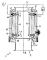
- FIGS. 1 to 3 A first exemplary embodiment of a measuring arrangement 1 according to the invention is shown in FIGS. 1 to 3 shown.
- the measuring arrangement 1 has a measuring tube 10, in which two electrodes 20, 20 'are arranged diametrically opposite one another.
- the measuring tube 10 has a tube wall 11, which is formed at the level of the electrodes 20 insulating.
- the electrode 20 is elongate and has a rectangular contact surface with the tube interior and with the liquid to be measured.
- the electrode 20 is arranged according to the invention so that its longitudinal axis is parallel to the tube axis 3 of the measuring tube 10, that is, that the elongate electrode 20 extends along the tube axis 3.
- the second electrode 20 ' is designed analogously to the first electrode 20.
- the measuring tube 10 is shown in its operating position, in which the measuring tube 10 and thus its tube axis 3 are perpendicular.
- the measuring tube 10 can serve according to the invention in a particularly simple manner for level determination.
- the measuring tube 10 can be traversed by the liquid to be measured in the direction of arrow A.
- the tube wall 11 of the measuring tube 10 is made of an insulating material, such as plastic.
- the electrodes 20, 20 lie directly against the tube wall 11 of the measuring tube 10.
- the measuring tube 10 in the region of the electrodes 20 has a rectangular, in particular square, tube cross-section, in particular in FIG FIG. 3 is recognizable.
- the measuring tube 10 has connections 14, 15, on which flange-type connecting devices are provided.
- the measuring tube has a circular inner cross-section for a particularly streamlined connection to conventional pipelines.
- FIGS. 4 and 5 A further embodiment of a measuring arrangement 1 according to the invention is shown in FIGS FIGS. 4 and 5 shown.
- a measuring tube 30 with an insulating tube wall 31 is also provided, on which two electrodes 40 and 40 'are arranged.
- the electrodes 40, 40 'rod-shaped with, for example, round, in particular circular cross-section, and spaced from the pipe wall 31 executed.
- spacers 42, 42', 43, 43 ' are provided on the tube wall 31. Of these spacers 42, 42 ', 43, 43', only the spacers 42 and 43 of the first electrode 40 will be described below.
- the spacers 42 and 43 are bolt-shaped and arranged so that their longitudinal axes extend radially to the tube axis 3.
- the bolt-shaped spacers 42, 43 penetrate the pipe wall 31 and are secured on the outside of the pipe wall 31 via screw nuts 44 and 45 on the pipe wall 31.
- the upper spacer 42 has a parallel to the tube axis 3 extending blind hole 55, which receives the rod-shaped electrode 40 and forms an axially fixed bearing for the electrode 40.
- the opposite lower spacer 43 has a through hole 54, which forms a movable bearing 51 for the electrode 40. This floating bearing 51 allows axial movement of the electrode 40 relative to the spacer 43. Different thermal expansions between the metallic electrode 40 and the existing plastic pipe wall 31 thus do not lead to thermal stress.
- the upper spacer 42 On the outside of the tube, the upper spacer 42 has an electrical contact 49.
- This contact 49 is conductively connected to the electrode 40 with a connecting line, not shown in the figures for clarity, which runs in the interior of the spacer 42.
- spacers 42 and 43 are disposed at the ends of the electrode 40. However, they can be placed anywhere along the electrode 40.
- a conductivity measuring device 80 is provided.
- This conductivity measuring device 80 serves to measure the conductivity of the liquid between the electrodes 40, 40 '.
- the conductivity measuring device 80 is connected via the respective contacts 49, 49 'to the electrodes 40 and 40'.
- the measuring tube 30 is formed both at the level of the electrodes 40, 40 'and in the region of the terminals 34, 35 with a circular inner cross-section.
- the measuring tube 30 has flange regions 36 and 37, respectively, which serve for connection to a pipeline system.
- the measuring tube 30 preferably be formed metallic.
- clamp seals 38 between flange areas 36 and 37 on the one hand and the pipe wall 31 on the other hand In order to be able to compensate for different temperature-dependent expansions of flange areas 36, 37 and plastic pipe wall 31, clamp seals 38 between flange areas 36 and 37 on the one hand and the pipe wall 31 on the other hand. 39 arranged.
- FIG. 6 shows a liquid receiving arrangement in which an inventive ⁇ e measuring arrangement 1 can be used.
- a milk receiving arrangement 70 has a delivery line 79, which on the one hand has an inlet 73 for liquid, in particular milk, and which, on the other hand, is connected to a collection tank 7, which is shown only schematically.
- a pump 71 for conveying the liquid is arranged in the course of the delivery line 79.
- a storage container 72 is provided in a side arm of the delivery line 79, which can serve to calm the liquid at the beginning and / or end of acceptance.
- a milk sensor 76, a pressure sensor 77 and a flow measuring device 78 are arranged.
- the milk sensor 76 and the pressure sensor 77 are arranged between the inlet 73 and the pump 71.
- the flow meter 78 is disposed between the pump 71 and the tank 7.
- the measuring arrangement 1 is provided on the suction side of the pump 71, that is to say on the side of the pump 71 which is in line connection with the inlet 73.
- the measuring arrangement 1 is connected directly upstream of the pump 71.
- the milk receiving arrangement 70 with the measuring arrangement 1 according to the invention can be operated as follows:
- the delivery line 79 and thus the measuring arrangement 1 are filled and the conductivity of the milk is determined by means of the measuring arrangement 1 when the product is at a standstill or at a slow conveying speed. Then, the delivery rate, for example by increasing the performance of the pump 71, increased until the desired negative pressure is established, which can be determined by means of the pressure sensor 77. The conductance is continuously controlled with the measuring arrangement 1. If the delivery rate is to be brought up to the cavitation limit, then the suction negative pressure is increased by increasing the pumping power until the conductance measured by the measuring arrangement 1 decreases. This decrease in conductivity is due to the smallest gas bubbles that form due to cavitation. The detection of the cavitation by means of the measuring arrangement 1 makes it possible to regulate the pumping power in such a way that the pump 71 is currently working at the cavitation boundary.
- the measured values of the flow measuring device 78 can be corrected with the filling degree measured values of the measuring arrangement 1.
- the measuring arrangement 1 can serve as a level sensor.
- the milk is pumped out of the storage container 72, wherein the fill level in the delivery line 79 must, as a rule, be driven to a defined closure level in order to be able to precisely determine the acceptance volume. Because a difference between start level and stop level causes a volume difference, which must be taken into account.
- the measuring arrangement 1 can also be used for this process step since it emits a fill level-dependent signal and thus allows it to end at the end of acceptance to reach a predetermined level and / or to demonstrate differences in level between the start of acceptance and the end of acceptance.
Landscapes
- Physics & Mathematics (AREA)
- Life Sciences & Earth Sciences (AREA)
- General Physics & Mathematics (AREA)
- Chemical & Material Sciences (AREA)
- Health & Medical Sciences (AREA)
- Engineering & Computer Science (AREA)
- Pathology (AREA)
- Food Science & Technology (AREA)
- Fluid Mechanics (AREA)
- Analytical Chemistry (AREA)
- Biochemistry (AREA)
- General Health & Medical Sciences (AREA)
- Immunology (AREA)
- Chemical Kinetics & Catalysis (AREA)
- Animal Husbandry (AREA)
- Environmental Sciences (AREA)
- Electrochemistry (AREA)
- Thermal Sciences (AREA)
- Medicinal Chemistry (AREA)
- Investigating Or Analyzing Materials By The Use Of Electric Means (AREA)
- Sampling And Sample Adjustment (AREA)
- Dairy Products (AREA)
Description
Die Erfindung betrifft eine Messanordnung für eine Flüssigkeit, insbesondere zur Verwendung in einer Flüssigkeitsannahmeanordnung, bevorzugt Milchannahmeanordnung, gemäß dem Oberbegriff des Anspruchs 1. Eine solche Messanordnung ist ausgebildet mit einem Messrohr zum Durchleiten der Flüssigkeit und zwei länglichen Elektroden, die zumindest bereichsweise einander gegenüberliegend im Messrohr angeordnet sind.The invention relates to a measuring arrangement for a liquid, in particular for use in a liquid receiving arrangement, preferably milk receiving arrangement, according to the preamble of
Die Erfindung betrifft ferner die Verwendung einer solchen Messanordnung in einer Flüssigkeitsannahmeanordnung sowie ein Verfahren zum Betrieb einer Flüssigkeitsannahmeanordnung.The invention further relates to the use of such a measuring arrangement in a liquid receiving arrangement and to a method for operating a liquid receiving arrangement.
In der Milchwirtschaft werden täglich große Mengen Milch von den einzelnen Erzeugern (Bauern, Farmern) zu den Verarbeitern (Molkereien, Lebensmittelfabriken) befördert. Dieser Transport geschieht fast ausschließlich durch Milchsammelwagen. Solche Milchsammelwagen weisen einen oder mehrere Sammeltanks auf, sowie eine Milchannahmeanordnung, die zum Überführen der Milch in den Tank und zum Bestimmen der überführten Flüssigkeitsmenge dient.In dairy farming, large quantities of milk are transported daily from individual producers (farmers, farmers) to processors (dairies, food factories). This transport is almost exclusively done by milk collection trucks. Such milk bins have one or more collection tanks, as well as a milk receiving assembly for transferring the milk into the tank and determining the transferred amount of liquid.
Ein Beispiel einer derartigen Milchannahmeanordnung ist aus der
Ausführungsformen von Füllgradmesseinrichtungen beziehungsweise Gasanteilsmesseinrichtungen zur Verwendung in einer Milchannahmeanordnung gehen beispielsweise aus der nächstkommenden
Milchannahmeanordnungen wie beispielsweise in der
Bei der Übergabe fließt die Milch bei gegebenen Annahmebedingungen umso schneller, je größer der Unterdruck am Pumpeneingang, also der Saugseite ist. Obwohl es im Hinblick auf den Zeitfaktor und die Wirtschaftlichkeit erstrebenswert wäre, eine möglichst große Pumpleistung zu realisieren, kann die Pumpleistung in der Praxis durch das Auftreten von Kavitation beschränkt sein. Kavitation, das heißt die lokale Verdampfung infolge örtlichen Unterdrucks, ist ein bekanntes Phänomen und beispielsweise in der
Zum Nachweis von Kavitation in verschiedenen Situationen sind Kavitationssensoren bekannt. So ist gemäß der
Aus der
Aus der
Durch den Milchtransport entstehen Kosten, die es zu minimieren gilt. Hierzu bedient man sich zum einen der Tourenoptimierung. Zum anderen wird versucht, die Annahmeleistung der Milchsammelwagen möglichst hoch zu wählen, wobei beachtet werden muss, dass die Milch nicht beschädigt werden darf. Schließlich kann eine Kostenreduktion durch Bereitstellung einer besonders kostengünstigen und wirtschaftlichen Annahmeanordnung erreicht werden.Milk transport creates costs that have to be minimized. For this purpose, one uses the tour optimization. On the other hand, it is attempted to select as high as possible the intake capacity of the milk collection vehicles, whereby it must be ensured that the milk must not be damaged. Finally, a cost reduction can be achieved by providing a particularly cost-effective and economical acceptance arrangement.
Aufgabe der Erfindung ist es, eine Messanordnung, insbesondere für eine Milchannahmeanordnung, und Verfahren zum Betrieb solcher Anordnungen anzugeben, die eine besonders große Einsatzvielfalt und eine besonders hohe Wirtschaftlichkeit gewährleisten. The object of the invention is to provide a measuring arrangement, in particular for a milk receiving arrangement, and method for operating such arrangements, which ensure a particularly large variety of applications and a particularly high efficiency.
Die Aufgabe wird erfindungsgemäß durch eine Messanordnung mit den Merkmalen des Anspruchs 1, der Verwendung einer solchen Messanordnung gemäß Anspruch 11 und einem Verfahren zum Betrieb einer Milchannahmeanordnung mit den Merkmalen des Anspruchs 12 gelöst. Bevorzugte Ausführungsbeispiele sind in den abhängigen Ansprüchen angegeben.The object is achieved by a measuring arrangement with the features of
Die erfindungsgemäße Messanordnung ist dadurch gekennzeichnet, dass die Messanordnung zur Kavitationsmessung mit der Flüssigkeit befüllbar ist, wobei das Auftreten von Kavitation durch eine Änderung der Leitfähigkeit zwischen den beiden Elektrode aufgrund von Kavitationsblosen erkannt wird und die Messanordnung in einem Förderbetrieb von der Flüssigkeit, In senkrechter Richtung durchströmt wird.The measuring arrangement according to the invention is characterized in that the measurement arrangement for measuring cavitation can be filled with the liquid, wherein the occurrence of cavitation is detected by a change in the conductivity between the two electrodes due to cavitation without and the measuring arrangement is flowed through in a conveying operation by the liquid, in the vertical direction.
Gemäß einem Grundgedanken der Erfindung wird eine Messanordnung bereitgestellt, die eine Leitfähigkeitsmessung der durchfließenden Flüssigkeit erlaubt. Aufgrund ihrer besonderen Elektrodenanordnung kann dabei ein und dieselbe Messanordnung für mindestens drei verschiedene Funktionen eingesetzt werden. So kann durch Leitfähigkeitsmessung zwischen den Elektroden zum einen der Füllgrad, das heißt der Flüssigkeits- beziehungsweise Gasanteil in der Flüssigkeit bestimmt werden. Der hierbei bestimmte Füllgrad kann dazu verwendet werden, die Messergebnisse einer Durchflussmesseinrichtung im Hinblick auf Gasanteile zu korrigieren. Darüber hinaus fungiert die Messanordnung als Kavitationssensor. Denn tritt in der Flüssigkeit Kavitation auf, so kommt es aufgrund der Kavitationsblasen zu einer Änderung der Leitfähigkeit zwischen den beiden Elektroden. Wird dieser Effekt nachgewiesen, so kann die Fördergeschwindigkeit, der Saugdruck und/oder die Leistung einer Förderpumpe entsprechend verringert werden, so dass die Kavitation wieder unterbunden ist.According to a basic idea of the invention, a measuring arrangement is provided which allows a conductivity measurement of the liquid flowing through. Due to their special electrode arrangement, one and the same measuring arrangement can be used for at least three different functions. Thus, by conductivity measurement between the electrodes on the one hand, the degree of filling, that is, the liquid or gas content in the liquid can be determined. The degree of filling determined in this case can be used to correct the measurement results of a flow measuring device with regard to gas fractions. In addition, the measuring arrangement acts as a cavitation sensor. For if cavitation occurs in the liquid, cavitation bubbles cause a change in the conductivity between the two electrodes. If this effect is detected, then the conveying speed, the suction pressure and / or the power of a feed pump can be reduced accordingly, so that the cavitation is prevented again.
Schließlich kann die erfindungsgemäße Messanordnung aufgrund der Elektrodenanordnung aber auch als Niveausensor verwendet werden, um beispielsweise nach Abschluss der Übergabe das Füllniveau in einem Förderleitungsverlauf zu bestimmen. Denn aufgrund der erfindungsgemäßen Anordnung von Elektroden und Messrohr stehen die Elektroden zumindest annähernd senkrecht und somit rechtwinklig zur Flüssigkeitsoberfläche, die am Abschluss der Übergabe das Füllniveau definiert. Aufgrund dieser senkrechten Anordnung hat eine Füllniveauänderung eine deutliche Änderung des Leitfähigkeitswertes zwischen den Elektroden zur Folge, so dass durch Leitfähigkeitsmessung ein besonders repräsentatives Signal für das Füllniveau erhalten werden kann. Der gleichzeitig vorgesehene erfindungsgemäß senkrechte Rohrverlauf hat, insbesondere bei konstantem Rohrquerschnitt im Bereich der Elektroden, dabei überdies zur Folge, dass eine mathematisch besonders einfache Beziehung zwischen dem gemessenen Leitfähigkeitswert und dem Füllniveau besteht, was die Auswertung stark vereinfacht.Finally, because of the electrode arrangement, the measuring arrangement according to the invention can also be used as a level sensor in order to determine, for example after completion of the transfer, the fill level in a delivery line course. Because of the inventive arrangement of electrodes and measuring tube, the electrodes are at least approximately perpendicular and thus perpendicular to the liquid surface, which defines the filling level at the conclusion of the transfer. Due to this vertical arrangement, a filling level change results in a significant change in the conductivity value between the electrodes, so that a particularly representative signal for the filling level can be obtained by conductivity measurement. The simultaneously provided according to the invention vertical pipe course has, moreover, in particular with constant pipe cross-section in the region of the electrodes result in a mathematically particularly simple relationship between the measured conductivity value and the filling level, which greatly simplifies the evaluation.
Unter der Rohrachse kann insbesondere die Längs- und/oder Symmetrieachse des Messrohres verstanden werden. Unter dem erfindungsgemäßen Verlauf der Elektroden längs der Rohrachse kann insbesondere verstanden werden, dass die Längsachsen der Elektroden (das heißt jene Achsen der Elektroden, welche der Richtung der größten Elektrodenausdehnung entsprechen), parallel zur Rohrachse verlaufen.In particular, the longitudinal axis and / or the symmetry axis of the measuring tube can be understood as the tube axis. The course of the electrodes according to the invention along the tube axis can be understood in particular to mean that the longitudinal axes of the electrodes (that is to say those axes of the electrodes which correspond to the direction of the largest electrode extent) run parallel to the tube axis.
Auch kann dieser Gedanken beinhalten, dass die Elektrodenausdehnung in Richtung der Rohrachse größer ist als quer zur Rohrachse, insbesondere um zumindest den Faktor 2 oder 5 größer. Die Erfindung beinhaltet somit, dass die Elektroden in Strömungsrichtung der Flüssigkeit verlaufen, welche im Bereich der Elektroden die Senkrechte ist.Also, this idea may include that the electrode extension in the direction of the tube axis is greater than transverse to the tube axis, in particular by at least a factor of 2 or 5 larger. The invention thus includes that the electrodes extend in the direction of flow of the liquid, which is the vertical in the region of the electrodes.
Die Elektroden können beispielsweise zumindest eine rechteckige Kontaktoberfläche für die Flüssigkeit aufweisen, wobei dann erfindungsgemäß die längere Rechteckseite parallel zur Rohrachse des Messrohres verläuft. Die Elektroden können aber beispielsweise auch stabförmig ausgebildet sein, wobei dann die Längs- oder Symmetrieachse des Stabes parallel zur Rohrachse verlaufen kann.By way of example, the electrodes can have at least one rectangular contact surface for the liquid, in which case according to the invention the longer rectangle side runs parallel to the tube axis of the measuring tube. However, the electrodes can also be designed, for example, rod-shaped, in which case the longitudinal or symmetry axis of the rod can run parallel to the tube axis.
Das erfindungsgemäße Messrohr weist zweckmäßigerweise eine Zulauföffnung sowie eine Auslauföffnung auf, so dass die zu charakterisierende Flüssigkeit durch das Messrohr hindurchgeleitet werden kann. Im Bereich dieser Öffnungen sind geeigneterweise Anschlüsse, insbesondere Flanschelemente vorgesehen, so dass das Messrohr in einen Förderleitungsverlauf einer Annahmeanordnung eingebaut werden kann. Im Bereich der Elektroden kann das Messrohr beispielsweise einen runden, insbesondere kreisrunden, einen rechteckigen oder einen quadratischen Innenquerschnitt aufweisen. Sofern im Bereich der Elektroden ein eckiger Querschnitt vorgesehen ist, ist es vorteilhaft, dass das Messrohr im Bereich der Öffnungen und/oder Anschlüsse einen runden Innenquerschnitt aufweist, so dass ein strömungstechnisch günstiger Übergang zum Leitungssystem gegeben ist. Erfindungsgemäß weist das Messrohr eine zum Beispiel hohlzylindrische Rohrwand auf. Diese Rohrwand kann eine Messkammer im Inneren des Rohres definieren, die von der Flüssigkeit durchströmt wird, und mit der die Elektroden in Kontakt stehen.The measuring tube according to the invention expediently has an inlet opening and an outlet opening, so that the liquid to be characterized can be passed through the measuring tube. Connections, in particular flange elements, are suitably provided in the region of these openings, so that the measuring tube can be installed in a delivery line course of an acceptance arrangement. In the region of the electrodes, the measuring tube may, for example, have a round, in particular circular, a rectangular or a square inner cross section. If an angular cross-section is provided in the region of the electrodes, it is advantageous for the measuring tube to have a round inner cross-section in the region of the openings and / or connections, so that a fluidically favorable transition to the line system is provided. According to the invention, the measuring tube has, for example, a hollow-cylindrical tube wall. This tube wall can define a measuring chamber in the interior of the tube through which the liquid flows and with which the electrodes are in contact.
Besonders vorteilhaft ist es, dass die Rohrwand zumindest an der Rohrinnenseite ein elektrisches Isolatormaterial aufweist. Gemäß dieser Ausführungsform ist die Rohrwand an ihrer Kontaktfläche mit der zu messenden Flüssigkeit nichtleitend ausgebildet, was im Hinblick auf die Messgenauigkeit vorteilhaft sein kann. Die Rohrwand kann auch zur Gänze aus dem Isolatormaterial bestehen. Bei dem Isolatormaterial kann es sich insbesondere um ein Kunststoffmaterial handeln. Die Elektroden sind geeigneterweise für einen elektrischen Kontakt mit der Flüssigkeit ausgebildet, das heißt sie sind im Inneren des Messrohres zumindest bereichsweise mit einer elektrisch leitenden Oberfläche ausgeführt.It is particularly advantageous that the tube wall has an electrical insulator material at least on the inner side of the tube. According to this embodiment, the pipe wall is formed on its contact surface with the liquid to be measured non-conductive, which may be advantageous in terms of measurement accuracy. The pipe wall can also consist entirely of the insulator material. The insulator material may in particular be a plastic material. The electrodes are suitably designed for electrical contact with the liquid which means they are at least partially carried out in the interior of the measuring tube with an electrically conductive surface.
Eine besonders robuste Ausführung ist nach der Erfindung dadurch gegeben, dass die Elektroden an der Rohrwand des Messrohres anliegen. Beispielsweise können in der Rohrwand Ausnehmungen für die Elektroden vorgesehen sein, in denen die Elektroden aufgenommen sind.A particularly robust embodiment is given according to the invention in that the electrodes abut against the tube wall of the measuring tube. For example, recesses may be provided in the tube wall for the electrodes, in which the electrodes are accommodated.
Insbesondere aus fertigungstechnischen Gründen können die Elektroden jedoch auch von der Rohrwand des Messrohres beabstandet sein. Eine solche Ausführungsform erlaubt auch ein besonders einfaches Auswechseln der Elektroden.In particular, for manufacturing reasons, however, the electrodes can also be spaced from the tube wall of the measuring tube. Such an embodiment also allows a particularly simple replacement of the electrodes.
Eine weitere vorteilhafte Ausführungsform der Erfindung besteht darin, dass an der Rohrwand Abstandshalter vorgesehen sind, welche in das Innere des Messrohres vorstehen, und an denen die Elektroden gehaltert sind. Die Abstandshalter können beispielsweise zylindrisch ausgebildet sein. Zweckmäßigerweise verlaufen die Längsachsen der Abstandshalter quer, insbesondere radial, zur Rohrachse.A further advantageous embodiment of the invention is that spacers are provided on the pipe wall, which protrude into the interior of the measuring tube, and on which the electrodes are mounted. The spacers may be cylindrical, for example. Conveniently, the longitudinal axes of the spacers extend transversely, in particular radially, to the tube axis.
Weiterhin ist es fertigungstechnisch besonders zweckmäßig, dass zumindest einer der Abstandshalter die Rohrwand durchdringt. In diesem Fall kann der Abstandshalter besonders einfach montiert werden, zum Beispiel durch Befestigungsmittel wie Schraubenmuttern oder andere an der Rohraußenseite. Sofern ein Abstandshalter die Rohrwand durchdringt, ist an diesem zweckmäßigerweise eine Dichtung angeordnet, um ein Austreten von Flüssigkeit aus dem Rohrinneren im Bereich des Abstandshalters zu verhindern. Vorzugsweise können alle Abstandshalter die Rohrwand durchdringen.Furthermore, it is particularly advantageous in terms of manufacturing that at least one of the spacers penetrates the pipe wall. In this case, the spacer can be mounted particularly easily, for example by fastening means such as nuts or other on the tube outside. If a spacer penetrates the pipe wall, a seal is expediently arranged thereon in order to prevent leakage of liquid from the interior of the pipe in the region of the spacer. Preferably, all spacers can penetrate the pipe wall.
Eine weitere bevorzugte Ausführungsform der Erfindung besteht darin, dass zumindest einer der Abstandshalter ein elektrisches Isolatormaterial aufweist. Hierdurch können unerwünschte Nebenschlüsse verhindert werden und die Messgenauigkeit erhöht werden. Bei dem elektrischen Isolatormaterial kann es sich insbesondere um ein Kunststoffmaterial handeln. Es kann ausreichend sein, dass der Abstandshalter das elektrische Isolatormaterial an seiner Oberfläche aufweist. Der Abstandshalter kann aber auch massiv aus dem elektrischen Isolatormaterial gefertigt sein. Vorzugsweise weisen alle Abstandshalter ein elektrisches Isolatormaterial auf.A further preferred embodiment of the invention is that at least one of the spacers comprises an electrical insulator material. As a result, unwanted shunts can be prevented and the measurement accuracy can be increased. The electrical insulator material may in particular be a plastic material. It may be sufficient that the spacer has the electrical insulator material on its surface. The spacer may also be made solid from the electrical insulator material. Preferably, all spacers on an electrical insulator material.
Eine weitere vorteilhafte Weiterbildung der Erfindung besteht darin, dass zumindest einer der Abstandshalter, z. B. in seinem Inneren, eine Anschlussleitung für einen elektrischen Kontakt mit der gehalterten Elektrode aufweist. In diesem Fall dient der Abstandshalter nicht nur zum Festlegen der Elektrode, sondern auch zum elektrischen Kontaktieren der Elektrode. Zweckmäßigerweise ist jeder Elektrode zumindest ein Abstandshalter zugeordnet, welcher eine solche Anschlussleitung aufweist.A further advantageous embodiment of the invention is that at least one of the spacers, for. B. in its interior, a connecting line for electrical contact with the content Erten electrode. In this case, the spacer serves not only for fixing the electrode but also for electrically contacting the electrode. Appropriately, each electrode is associated with at least one spacer, which has such a connecting line.
Eine besonders einfache und zugleich zuverlässige Halterung der Elektroden kann dadurch gewährleistet werden, dass zumindest eine der Elektroden an zumindest zwei Halterungsstellen am Messrohr gehaltert ist. Die Halterung erfolgt dabei vorzugsweise über die vorgenannten Abstandshalter. Die Halterungsstellen können insbesondere in zwei gegenüberliegenden Endbereichen der Elektrode vorgesehen sein. Besonders bevorzugt ist es, dass die Halterung der Elektrode an zumindest einer der Halterungsstellen über ein Loslager erfolgt. Das Loslager lässt eine Wärmedehnung und/oder Wärmekontraktion der Elektrode zu. Ein solches Loslager beugt somit thermischen Verspannungen aufgrund unterschiedlicher Ausdehnungskoeffizienten von Elektrode und Messrohrwand vor. In diesem Zusammenhang ist zu beachten, dass im Betrieb Temperaturunterschiede von mehr als 80°C auftreten könne, wobei sich die Temperaturunterschiede insbesondere zwischen der Produkttemperatur und der Temperatur ergeben können, welche bei einem Reinigungsverfahren, insbesondere einem Cleaning in Place (CIP) Verfahren, herrscht. Eine metallische Elektrode kann sich dabei unter Umständen wenig stark ausdehnen als eine isolierende Rohrwand. Das Loslager kann beispielsweise als Bohrung im Abstandshalter ausgebildet sein. An der zweiten Halterungsstelle ist bevorzugt ein Fixlager gegeben, welches beispielsweise durch ein Sackloch im Abstandshalter gebildet sein kann. Zweckmäßigerweise sind beide Elektroden wie beschrieben gehaltert.A particularly simple and at the same time reliable mounting of the electrodes can be ensured by holding at least one of the electrodes on at least two support points on the measuring tube. The holder is preferably carried out via the aforementioned spacers. The support locations may be provided in particular in two opposite end regions of the electrode. It is particularly preferred that the holder of the electrode is carried on at least one of the support points via a floating bearing. The floating bearing allows for thermal expansion and / or thermal contraction of the electrode. Such a floating bearing thus prevents thermal stresses due to different expansion coefficients of electrode and measuring tube wall. In this context, it should be noted that temperature differences of more than 80 ° C may occur during operation, whereby the temperature differences may in particular arise between the product temperature and the temperature prevailing in a cleaning process, in particular a cleaning in place (CIP) process , Under certain circumstances, a metallic electrode may not expand as much as an insulating tube wall. The floating bearing can be formed for example as a bore in the spacer. At the second support point, a fixed bearing is preferably provided, which may be formed for example by a blind hole in the spacer. Conveniently, both electrodes are supported as described.
Erfindungsgemäß werden die Elektroden für eine Leitfähigkeitsmessung eingesetzt. Demgemäß ist eine Leitfähigkeitsmesseinrichtung vorgesehen, welche zum Messen der Leitfähigkeit zwischen den beiden Elektroden mit den Elektroden in Leitungsverbindung steht. Die Leitfähigkeitsmesseinrichtung kann beispielsweise eine Spannungsquelle und eine Strommesseinrichtung aufweisen.According to the invention, the electrodes are used for a conductivity measurement. Accordingly, a conductivity measuring device is provided, which is in line connection with the electrodes for measuring the conductivity between the two electrodes. The conductivity measuring device can have, for example, a voltage source and a current measuring device.
Im Hinblick auf die Verwendung in einer Annahmeanordnung ist es vorteilhaft, dass eine Pumpe zum Fördern der Flüssigkeit vorgesehen ist. Zweckmäßigerweise ist das Messrohr an der Saugseite der Pumpe an die Pumpe angeschlossen. Auf diese Weise kann die Messanordnung die drei vorgenannten Funktionen Kavitationsmessung, Füllgradmessung und Niveaumessung unmittelbar erfüllen.With regard to the use in a receiving arrangement, it is advantageous that a pump is provided for conveying the liquid. Appropriately, that is Measuring tube on the suction side of the pump connected to the pump. In this way, the measuring arrangement can directly fulfill the three aforementioned functions cavitation measurement, filling degree measurement and level measurement.
Im Hinblick auf die dreifache Funktionalität ist es überdies vorteilhaft, dass das Messrohr leitungsmäßig zwischen einem Speicherbehälter für die Flüssigkeit und der Pumpe angeordnet ist, und/oder dass das Messrohr leitungsgemäß zwischen einem Zulauf für die Flüssigkeit und der Pumpe angeordnet ist. Ein solcher Speicherbehälter kann beispielsweise für die Entgasung der Flüssigkeit vorgesehen sein und an einer Abzweigung der Förderleitung angeordnet sein. Unter einem Zulauf kann eine Zuführöffnung für die Flüssigkeit verstanden werden, die beispielsweise an einem Schlauch und/oder Saugrüssel ausgebildet sein kann.With regard to the triple functionality, it is also advantageous that the measuring tube is arranged linewise between a storage container for the liquid and the pump, and / or that the measuring tube is arranged according to the conduit between an inlet for the liquid and the pump. Such a storage container can be provided, for example, for the degassing of the liquid and be arranged at a branch of the delivery line. An inlet may be understood to mean a feed opening for the liquid, which may be formed, for example, on a hose and / or a proboscis.
Die Erfindung betrifft auch die Verwendung der erfindungsgemäßen Messanordnung in einer Flüssigkeitsannahmeanordnung, insbesondere einer Milchannahmeanordnung. Eine solche Annahmeanordnung weist bevorzugt eine Förderleitung auf, die einerseits einen Zulauf für die Flüssigkeit und andererseits eine Verbindung für einen Sammeltank aufweist, und vorzugsweise auch eine Pumpe und/oder eine Durchflussmesseinrichtung.The invention also relates to the use of the measuring arrangement according to the invention in a liquid receiving arrangement, in particular a milk receiving arrangement. Such an acceptance arrangement preferably has a delivery line which on the one hand has an inlet for the liquid and on the other hand a connection for a collecting tank, and preferably also a pump and / or a flow measuring device.
Erfindungsgemäß kann eine Recheneinrichtung vorgesehen sein, die zur Füllgradkorrektur der Ergebnisse der Durchflussmessung sowohl mit der Durchflussmesseinrichtung als auch mit der erfindungsgemäßen Messanordnung, insbesondere mit deren Elektroden und/oder deren Leitfähigkeitsmesseinrichtung, in Signalverbindung steht.According to the invention, a computing device may be provided which is in signal communication with the fill-flow correction of the results of the flow measurement both with the flow measuring device and with the measuring arrangement according to the invention, in particular with their electrodes and / or their conductivity measuring device.
Es ist erfindungsgemäß, dass die Messanordnung zur Kavitationsmessung, zur Füllgradmessung und zur Niveaubestimmung eingesetzt wird. Dies entspricht der zuvor beschriebenen dreifachen Funktionalität der Messanordnung.It is according to the invention that the measuring arrangement is used for cavitation measurement, for filling degree measurement and for level determination. This corresponds to the triple functionality of the measuring arrangement described above.
Die Erfindung betrifft auch ein Verfahren zum Betrieb einer Flüssigkeitsannahmeanordnung, insbesondere Milchannahmeanordnung, bei dem mit einer erfindungsgemäßen Messanordnung die Leitfähigkeit der geförderten Flüssigkeit gemessen wird, und die Leistung einer in der Flüssigkeitsannahmeanordnung vorgesehenen Pumpe reduziert wird, wenn mittels der Messanordnung Kavitation nachgewiesen wird. Demgemäß wird der Saugdruck reduziert, wenn Kavitation nachgewiesen wird. Dies erlaubt es, die Pumpenleistung so zu regeln, dass Kavitation gerade noch vermieden wird, so dass ein maximaler Durchsatz ohne Beschädigung der Milch erreicht wird.The invention also relates to a method for operating a liquid receiving arrangement, in particular milk receiving arrangement, wherein the conductivity of the conveyed liquid is measured with a measuring arrangement according to the invention, and the power of a pump provided in the liquid receiving arrangement is reduced when cavitation is detected by means of the measuring arrangement. Accordingly, the suction pressure is reduced when Cavitation is detected. This makes it possible to regulate the pump performance so that cavitation is barely avoided, so that maximum throughput is achieved without damaging the milk.
Die Erfindung wird nachfolgend anhand bevorzugter Ausführungsbeispiele näher erläutert, welche schematisch in den beiliegenden Figuren dargestellt sind. In den Figuren zeigen:
Figur 1- eine perspektivische Ansicht einer ersten Ausführungsform einer erfindungsgemäßen Messanordnung;
- Figur 2
- eine Längsschnittansicht der Messanordnung aus
Figur 1 ; Figur 3- eine Querschnittansicht der Messanordnung aus
Figur 1 und 2 ; - Figur 4
- eine Längsschnittansicht einer erfindungsgemäßen Messanordnung gemäß einer zweiten Ausführungsform;
- Figur 5
- die Messanordnung aus
Figur 4 in einer um 90 Grad versetzten Längsschnittansicht; und - Figur 6
- eine Flüssigkeitsannahmeanordnung, in welcher eine erfindungsgemä-βe Messanordnung einsetzbar ist.
- FIG. 1
- a perspective view of a first embodiment of a measuring arrangement according to the invention;
- FIG. 2
- a longitudinal sectional view of the measuring arrangement
FIG. 1 ; - FIG. 3
- a cross-sectional view of the measuring arrangement
FIGS. 1 and 2 ; - FIG. 4
- a longitudinal sectional view of a measuring arrangement according to the invention according to a second embodiment;
- FIG. 5
- the measuring arrangement
FIG. 4 in a 90 degree offset longitudinal section view; and - FIG. 6
- a liquid receiving arrangement in which a measuring arrangement according to the invention can be used.
Ein erstes Ausführungsbeispiel einer erfindungsgemäßen Messanordnung 1 ist in
Wie
In
Die Rohrwand 11 des Messrohres 10 ist aus einem Isolatormaterial, beispielsweise Kunststoff, ausgeführt. Im Ausführungsbeispiel der
Im Ausführungsbeispiel der
Eine weitere Ausführungsform einer erfindungsgemäßen Messanordnung 1 ist in den
Beim Ausführungsbeispiel der
Die Abstandshalter 42 und 43 sind bolzenförmig ausgebildet und so angeordnet, dass ihre Längsachsen radial zur Rohrachse 3 verlaufen. Die bolzenförmigen Abstandshalter 42, 43 durchdringen die Rohrwand 31 und sind auf der Außenseite der Rohrwand 31 über Schraubmuttern 44 beziehungsweise 45 an der Rohrwand 31 gesichert. Zum Abdichten der Durchgangsöffnungen, welche für die Abstandshalter 42, 43 in der Rohrwand 31 vorgesehen sind, sind an den Abstandshaltern 42, 43 als Dichtringe ausgebildete Dichtungen 46 beziehungsweise 47 vorgesehen, die einerseits an der Rohrwand 31 und andererseits am jeweiligen Abstandshalter 42 beziehungsweise 43 anliegen.The
Der obere Abstandshalter 42 weist ein parallel zur Rohrachse 3 verlaufendes Sackloch 55 auf, welches die stabförmige Elektrode 40 aufnimmt und ein axial festes Lager für die Elektrode 40 bildet. Der gegenüberliegende untere Abstandshalter 43 weist eine durchgehende Bohrung 54 auf, welche ein Loslager 51 für die Elektrode 40 bildet. Dieses Loslager 51 erlaubt eine axiale Bewegung der Elektrode 40 relativ zum Abstandshalter 43. Unterschiedliche thermische Ausdehnungen zwischen der metallischen Elektrode 40 und der aus Kunststoff bestehenden Rohrwand 31 führen somit nicht zu einer thermischen Verspannung.The
An der Rohraußenseite weist der obere Abstandshalter 42 einen elektrischen Kontakt 49 auf. Dieser Kontakt 49 ist mit einer in den Figuren der Übersichtlichkeit halber nicht dargestellten Anschlussleitung, die im Inneren des Abstandshalters 42 verläuft, mit der Elektrode 40 leitungsverbunden.On the outside of the tube, the
Im dargestellten Ausführungsbeispiel sind Abstandshalter 42 und 43 an den Enden der Elektrode 40 angeordnet. Sie können jedoch an beliebigen Orten entlang der Elektrode 40 platziert werden.In the illustrated embodiment,
Wie in
Im Ausführungsbeispiel der
Die beispielhaft als Milchannahmeanordnung 70 dargestellte Anordnung weist eine Förderleitung 79 auf, die einerseits einen Zulauf 73 für Flüssigkeit, insbesondere Milch aufweist, und die andererseits mit einem lediglich schematisch dargestellten Sammeltank 7 verbunden ist. Im Verlauf der Förderleitung 79 ist eine Pumpe 71 zum Fördern der Flüssigkeit angeordnet. In einem Seitenarm der Förderleitung 79 ist ein Speicherbehälter 72 vorgesehen, der zum Beruhigen der Flüssigkeit beim Annahmebeginn und/oder Annahmeende dienen kann. Im Verlauf der Förderleitung 79 sind überdies ein Milchsensor 76, ein Drucksensor 77 und eine Durchflussmesseinrichtung 78 angeordnet. Der Milchsensor 76 und der Drucksensor 77 sind dabei zwischen dem Zulauf 73 und der Pumpe 71 angeordnet. Die Durchflussmesseinrichtung 78 hingegen ist zwischen der Pumpe 71 und dem Tank 7 angeordnet. Die Messanordnung 1 ist an der Saugseite der Pumpe 71 vorgesehen, das heißt an der Seite der Pumpe 71, welche mit dem Zulauf 73 in Leitungsverbindung steht. Die Messanordnung 1 ist dabei der Pumpe 71 unmittelbar vorgeschaltet.The arrangement illustrated by way of example as a milk receiving arrangement 70 has a
Die Milchannahmeanordnung 70 mit der erfindungsgemäßen Messanordnung 1 kann wie folgt betrieben werden:The milk receiving arrangement 70 with the measuring
Zu Beginn der Milchannahme wird die Förderleitung 79 und somit die Messanordnung 1 befüllt und der Leitwert der Milch bei stehendem Produkt oder langsamer Fördergeschwindigkeit mittels der Messanordnung 1 ermittelt. Dann wird die Förderleistung, beispielsweise durch Leistungssteigerung der Pumpe 71, erhöht, bis sich der gewünschte Unterdruck einstellt, was mittels des Drucksensors 77 bestimmt werden kann. Der Leitwert wird dabei fortwährend mit der Messanordnung 1 kontrolliert. Soll die Förderleistung bis an die Kavitationsgrenze herangeführt werden, so wird der Saugunterdruck durch Erhöhen der Pumpleistung so lange erhöht, bis der von der Messanordnung 1 gemessene Leitwert abnimmt. Diese Leitwertabnahme ist auf kleinste Gasbläschen zurückzuführen, die sich durch Kavitation bilden. Der Nachweis der Kavitation mittels der Messanordnung 1 ermöglicht es, die Pumpleistung so zu regeln, dass die Pumpe 71 gerade an der Kavitationsgrenze arbeitet.At the beginning of the milk intake, the
Zum Ende der Annahme hin oder bei Sogbildung kann es zu einem Lufteintrag in der Milch kommen, der nicht auf Kavitation zurückzuführen ist. Auch dieser Lufteintrag wird mittels der Messanordnung 1 gemessen und die Pumpleistung entsprechend reduziert, wodurch unter Umständen der Strudel verkürzt werden kann und somit der Lufteintrag verringert werden kann. Damit der Lufteintrag nicht zu verfälschten Messwerten bei der Durchflussmessung führt, können die Messwerte der Durchflussmesseinrichtung 78 mit den Füllgradmesswerten der Messanordnung 1 korrigiert werden.At the end of the assumption or during suction, there may be an intake of air in the milk, which is not due to cavitation. This air intake is also measured by means of the measuring
Wird der Lufteintrag trotz Reduzierung der Saugleistung der Pumpe 71 größer, so kann in der Regel von einem Abschluss der Annahme ausgegangen werden. Fällt zusätzlich das Signal des Milchsensors 76 ab, so wird die Pumpe 71 gestoppt und der Speicherbehälter 72 wird aktiviert, der die Förderleitung 79 im Bereich des Zulaufs 73 leersaugt.If the air intake despite the reduction of the suction power of the
Zum Ende der Annahme kann die Messanordnung 1 als Niveausensor dienen. Zum Annahmeende wird die Milch aus dem Speicherbehälter 72 gepumpt, wobei das Füllniveau in der Förderleitung 79 aus messtechnischen und eichtechnischen Gesichtspunkten in der Regel auf ein definiertes Abschlussniveau gefahren werden muss, um das Annahmevolumen exakt bestimmen zu können. Denn eine Differenz zwischen Startniveau und Stoppniveau bedingt einen Volumenunterschied, der berücksichtigt werden muss. Auch für diesen Prozessschritt kann die Messanordnung 1 verwendet werden, da sie ein füllniveauabhängiges Signal abgibt und es somit erlaubt, zum Annahmeende ein vorbestimmtes Niveau anzufahren und/oder Niveauunterschiede zwischen Annahmebeginn und Annahmeende nachzuweisen.At the end of the assumption, the measuring
Claims (12)
- A measuring arrangement (1) for a liquid having- a measuring tube (10, 30) through which the liquid is conducted,- two elongated electrodes (20, 40) which are arranged opposite one another in the measuring tube (10, 30) at least in places, and- a conductivity measuring device (80), which is in line connection to the electrodes (20, 40) to measure the conductivity between the two electrodes (20, 40), wherein- the elongated electrodes (20, 40) run along the tube axis (3) of the measuring tube (10, 30) and- the tube axis (3) of the measuring tube (10, 30) runs at least approximately perpendicularly in the operating position in the region of the electrodes (20, 40),characterized in that
the measuring arrangement can be filled with liquid for cavitation measurement, wherein the occurrence of cavitation is identified by a change in conductivity between the two electrodes on account of cavitation bubbles and the liquid flows through the measuring arrangement in a perpendicular direction in a conveying operation. - The measuring arrangement (1) according to claim 1,
characterized in that
the measuring tube (10, 30) exhibits a tube wall (11, 31), which exhibits an electrical insulating material at least on the inside of the tube. - The measuring arrangement (1) according to one of the preceding claims,
characterized in that
the electrodes (20) lie against the tube wall (11) of the measuring tube (10). - The measuring arrangement (1) according to one of the claims 1 or 2,
characterized in that
the electrodes (40) are spaced apart from the tube wall (31) of the measuring tube (30). - The measuring arrangement (1) according to one of the preceding claims,
characterized in that
spacers (42, 43) are provided on the tube wall (31), which project into the inside of the measuring tube (30) and on which the electrodes (40) are mounted. - The measuring arrangement (1) according to claim 5,
characterized in that
at least one of the spacers (42, 43) penetrates the tube wall (31). - The measuring arrangement (1) according to one of the claims 5 or 6,
characterized in that
at least one of the spacers (42, 43) exhibits an electrical insulating material and
that at least one of the spacers (42) exhibits in its interior a connection line for an electrical contact with the mounted electrode. - The measuring arrangement (1) according to one of the preceding claims,
characterized in that
at least one of the electrodes (40) is mounted on at least two mounting points on the measuring tube (30), wherein the electrode (40) is mounted on at least one of the mounting points via a floating bearing (51). - The measuring arrangement (1) according to one of the preceding claims,
characterized in that
a pump (71) for conveying the liquid is present and that the measuring tube (10, 30) is connected to the pump (71) on the suction side of the pump (71). - The measuring arrangement (1) according to one of the preceding claims,
characterized in that
the measuring tube (10, 30) is arranged with line connection between a storage container (72) for the liquid and the pump (71) and/or that the measuring tube (10, 30) is arranged in line terms between an incoming line (73) for the liquid and the pump (71). - A use of the measuring arrangement (1) according to one of the preceding claims in a liquid collection arrangement (70) for cavitation measurement, for filling capacity measurement and for level determination.
- A method for operating a liquid collection arrangement (70) in which using a measuring arrangement (1) according to one of the claims 1 to 10 the conductivity of the conveyed liquid is measured and the output of a pump (71) present in the liquid collection arrangement (70) is reduced when cavitation is demonstrated by means of the measuring arrangement (1).
Priority Applications (1)
| Application Number | Priority Date | Filing Date | Title |
|---|---|---|---|
| PL10798265T PL2467682T3 (en) | 2009-12-18 | 2010-12-17 | Measurement device for a liquid, in particular for use in a milk collection arrangement, and method for operating a milk collection arrangement |
Applications Claiming Priority (2)
| Application Number | Priority Date | Filing Date | Title |
|---|---|---|---|
| DE102009058838A DE102009058838A1 (en) | 2009-12-18 | 2009-12-18 | Measuring arrangement for a liquid, in particular for use in a milk receiving arrangement, and method for operating a milk receiving arrangement |
| PCT/EP2010/007760 WO2011072874A2 (en) | 2009-12-18 | 2010-12-17 | Measurement array for a liquid, in particular for use in a milk collection array, and method for operating a milk collection array |
Publications (2)
| Publication Number | Publication Date |
|---|---|
| EP2467682A2 EP2467682A2 (en) | 2012-06-27 |
| EP2467682B1 true EP2467682B1 (en) | 2013-07-31 |
Family
ID=44022097
Family Applications (1)
| Application Number | Title | Priority Date | Filing Date |
|---|---|---|---|
| EP10798265.4A Active EP2467682B1 (en) | 2009-12-18 | 2010-12-17 | Measurement device for a liquid, in particular for use in a milk collection arrangement, and method for operating a milk collection arrangement |
Country Status (4)
| Country | Link |
|---|---|
| EP (1) | EP2467682B1 (en) |
| DE (1) | DE102009058838A1 (en) |
| PL (1) | PL2467682T3 (en) |
| WO (1) | WO2011072874A2 (en) |
Families Citing this family (1)
| Publication number | Priority date | Publication date | Assignee | Title |
|---|---|---|---|---|
| CN103674132B (en) * | 2013-12-25 | 2016-06-08 | 栾川龙宇钼业有限公司 | A kind of non-full stream pipe outlet flow measurement device and method |
Family Cites Families (13)
| Publication number | Priority date | Publication date | Assignee | Title |
|---|---|---|---|---|
| US3910216A (en) | 1974-06-10 | 1975-10-07 | Boeing Co | Hydrofoil cavitation sensing and control apparatus |
| US5251148A (en) | 1990-06-01 | 1993-10-05 | Valtek, Inc. | Integrated process control valve |
| NL1000471C1 (en) * | 1995-03-24 | 1996-09-26 | Maasland Nv | Quantity meter and device for milking animals, provided with such a meter. |
| DE19715480C2 (en) | 1997-04-14 | 1999-01-14 | Saskia Solar Und Energietechni | Vacuum pump system with a liquid ring pump |
| DE19725012C1 (en) | 1997-06-13 | 1998-11-05 | Brose Fahrzeugteile | Measuring physical or technical parameters of liquids, including highly viscous, doughy or pasty material |
| WO2000025125A1 (en) | 1998-10-28 | 2000-05-04 | Covaris, Inc. | Apparatus and methods for controlling sonic treatment |
| GB9921982D0 (en) | 1999-09-16 | 1999-11-17 | Secretary Trade Ind Brit | Cavitation sensor |
| DE10233312A1 (en) * | 2002-07-22 | 2004-03-04 | Westfaliasurge Gmbh | Determining volumetric flow of milk flowing during measurement process involves measuring time for milk with known cross-section to pass between measurement points |
| DE102005005295A1 (en) * | 2004-12-16 | 2006-06-22 | Bartec Gmbh | Fill level detector for fluid flowing in measuring chamber, has wall of measuring chamber made of electrically insulating material in region of electrodes |
| DE202004019442U1 (en) | 2004-12-16 | 2005-03-10 | Bartec Gmbh | Device for determining the degree of filling of a fluid |
| WO2007006311A1 (en) * | 2005-07-08 | 2007-01-18 | Aktieselskabet S. A. Christensen & Co. | A measuring device for milk flow |
| DE102006014207A1 (en) * | 2006-03-25 | 2007-09-27 | Westfaliasurge Gmbh | Milk collection container for milking e.g. cow, has energy source connected with two spaced apart connection points of electrode such that energy source is connected parallel with respect to electrode |
| WO2008141664A1 (en) | 2007-05-22 | 2008-11-27 | Bartec Gmbh | Method and device for determining volume during transfer of a liquid |
-
2009
- 2009-12-18 DE DE102009058838A patent/DE102009058838A1/en not_active Withdrawn
-
2010
- 2010-12-17 WO PCT/EP2010/007760 patent/WO2011072874A2/en not_active Ceased
- 2010-12-17 EP EP10798265.4A patent/EP2467682B1/en active Active
- 2010-12-17 PL PL10798265T patent/PL2467682T3/en unknown
Also Published As
| Publication number | Publication date |
|---|---|
| DE102009058838A1 (en) | 2011-06-22 |
| WO2011072874A2 (en) | 2011-06-23 |
| EP2467682A2 (en) | 2012-06-27 |
| WO2011072874A3 (en) | 2011-09-09 |
| PL2467682T3 (en) | 2014-05-30 |
Similar Documents
| Publication | Publication Date | Title |
|---|---|---|
| EP2095085B1 (en) | Adapter for pressure sensors | |
| EP2739944B1 (en) | Method for detecting a deposit formation or an abrasion in a flow meter | |
| DE102009027581B4 (en) | Measuring device comprising a measuring probe and a fastening device | |
| EP2166336B1 (en) | Method for monitoring the quality of a fuel containing alcohol in a storage tank | |
| WO2000012972A1 (en) | Device and method for determining volume | |
| WO2017108280A1 (en) | Field device of process measuring technology | |
| DE102016123489A1 (en) | level sensor | |
| EP2467682B1 (en) | Measurement device for a liquid, in particular for use in a milk collection arrangement, and method for operating a milk collection arrangement | |
| EP1597554B1 (en) | Method for determining at least one state parameter of a sealing system and sealing system | |
| DE102009036633B4 (en) | Measuring device | |
| DE102010011638A1 (en) | Capacitive level sensor and level detection method with a capacitive level sensor | |
| EP1764587A2 (en) | Magnetic-inductive flow meter with a grounding washer | |
| EP2947443B1 (en) | Manometer system | |
| DE102010008066B3 (en) | Buchholz relay | |
| DE102011084906A1 (en) | Method for monitoring pump for transporting liquid in industrial plant for production of e.g. cosmetic, involves detecting air bubble or froth in pump liquid by capacitive and/or conductive sensor arranged into housing portion | |
| DE102005005295A1 (en) | Fill level detector for fluid flowing in measuring chamber, has wall of measuring chamber made of electrically insulating material in region of electrodes | |
| EP4538581A1 (en) | Method for operating a condensate drain and condensate drain | |
| EP2199754B1 (en) | Method and device for transferring a liquid with one at least temporary gas inclusion and for determining the amount of transferred liquid | |
| DE102014102054A1 (en) | Level sensor with electrode monitoring | |
| EP2990777A1 (en) | Device and method for detecting properties or the filling level of a medium in a vessel | |
| DE3902107A1 (en) | Capacitive filling level and level measuring device | |
| DE102010035965A1 (en) | Pressure Transmitter | |
| DE102015011665A1 (en) | Method and system for determining the level of an electrically conductive medium in at least one container | |
| EP3449244B1 (en) | Arrangement and method for detecting damage to an inner coating of a container | |
| EP1339978A1 (en) | Device and method for measuring the injection quantity of injection nozzles, especially for motor vehicles |
Legal Events
| Date | Code | Title | Description |
|---|---|---|---|
| PUAI | Public reference made under article 153(3) epc to a published international application that has entered the european phase |
Free format text: ORIGINAL CODE: 0009012 |
|
| 17P | Request for examination filed |
Effective date: 20120302 |
|
| AK | Designated contracting states |
Kind code of ref document: A2 Designated state(s): AL AT BE BG CH CY CZ DE DK EE ES FI FR GB GR HR HU IE IS IT LI LT LU LV MC MK MT NL NO PL PT RO RS SE SI SK SM TR |
|
| GRAP | Despatch of communication of intention to grant a patent |
Free format text: ORIGINAL CODE: EPIDOSNIGR1 |
|
| DAX | Request for extension of the european patent (deleted) | ||
| GRAS | Grant fee paid |
Free format text: ORIGINAL CODE: EPIDOSNIGR3 |
|
| GRAA | (expected) grant |
Free format text: ORIGINAL CODE: 0009210 |
|
| AK | Designated contracting states |
Kind code of ref document: B1 Designated state(s): AL AT BE BG CH CY CZ DE DK EE ES FI FR GB GR HR HU IE IS IT LI LT LU LV MC MK MT NL NO PL PT RO RS SE SI SK SM TR |
|
| REG | Reference to a national code |
Ref country code: GB Ref legal event code: FG4D Free format text: NOT ENGLISH Ref country code: CH Ref legal event code: EP |
|
| REG | Reference to a national code |
Ref country code: AT Ref legal event code: REF Ref document number: 624913 Country of ref document: AT Kind code of ref document: T Effective date: 20130815 |
|
| REG | Reference to a national code |
Ref country code: IE Ref legal event code: FG4D Free format text: LANGUAGE OF EP DOCUMENT: GERMAN |
|
| REG | Reference to a national code |
Ref country code: DE Ref legal event code: R096 Ref document number: 502010004252 Country of ref document: DE Effective date: 20130926 |
|
| GRAT | Correction requested after decision to grant or after decision to maintain patent in amended form |
Free format text: ORIGINAL CODE: EPIDOSNCDEC |
|
| REG | Reference to a national code |
Ref country code: CH Ref legal event code: NV Representative=s name: TROESCH SCHEIDEGGER WERNER AG, CH |
|
| REG | Reference to a national code |
Ref country code: NL Ref legal event code: T3 |
|
| RAP2 | Party data changed (patent owner data changed or rights of a patent transferred) |
Owner name: BARTEC BENKE GMBH |
|
| REG | Reference to a national code |
Ref country code: LT Ref legal event code: MG4D |
|
| PG25 | Lapsed in a contracting state [announced via postgrant information from national office to epo] |
Ref country code: PT Free format text: LAPSE BECAUSE OF FAILURE TO SUBMIT A TRANSLATION OF THE DESCRIPTION OR TO PAY THE FEE WITHIN THE PRESCRIBED TIME-LIMIT Effective date: 20131202 Ref country code: HR Free format text: LAPSE BECAUSE OF FAILURE TO SUBMIT A TRANSLATION OF THE DESCRIPTION OR TO PAY THE FEE WITHIN THE PRESCRIBED TIME-LIMIT Effective date: 20130731 Ref country code: SE Free format text: LAPSE BECAUSE OF FAILURE TO SUBMIT A TRANSLATION OF THE DESCRIPTION OR TO PAY THE FEE WITHIN THE PRESCRIBED TIME-LIMIT Effective date: 20130731 Ref country code: CY Free format text: LAPSE BECAUSE OF FAILURE TO SUBMIT A TRANSLATION OF THE DESCRIPTION OR TO PAY THE FEE WITHIN THE PRESCRIBED TIME-LIMIT Effective date: 20130828 Ref country code: NO Free format text: LAPSE BECAUSE OF FAILURE TO SUBMIT A TRANSLATION OF THE DESCRIPTION OR TO PAY THE FEE WITHIN THE PRESCRIBED TIME-LIMIT Effective date: 20131031 Ref country code: LT Free format text: LAPSE BECAUSE OF FAILURE TO SUBMIT A TRANSLATION OF THE DESCRIPTION OR TO PAY THE FEE WITHIN THE PRESCRIBED TIME-LIMIT Effective date: 20130731 Ref country code: IS Free format text: LAPSE BECAUSE OF FAILURE TO SUBMIT A TRANSLATION OF THE DESCRIPTION OR TO PAY THE FEE WITHIN THE PRESCRIBED TIME-LIMIT Effective date: 20131130 |
|
| REG | Reference to a national code |
Ref country code: CH Ref legal event code: NV Representative=s name: PATENTANWALTSBUERO JEAN HUNZIKER AG, CH Ref country code: CH Ref legal event code: PCOW Free format text: NEW ADDRESS: BORSIGSTRASSE 10, 21465 REINBEK/HAMBURG (DE) |
|
| PG25 | Lapsed in a contracting state [announced via postgrant information from national office to epo] |
Ref country code: LV Free format text: LAPSE BECAUSE OF FAILURE TO SUBMIT A TRANSLATION OF THE DESCRIPTION OR TO PAY THE FEE WITHIN THE PRESCRIBED TIME-LIMIT Effective date: 20130731 Ref country code: SI Free format text: LAPSE BECAUSE OF FAILURE TO SUBMIT A TRANSLATION OF THE DESCRIPTION OR TO PAY THE FEE WITHIN THE PRESCRIBED TIME-LIMIT Effective date: 20130731 Ref country code: GR Free format text: LAPSE BECAUSE OF FAILURE TO SUBMIT A TRANSLATION OF THE DESCRIPTION OR TO PAY THE FEE WITHIN THE PRESCRIBED TIME-LIMIT Effective date: 20131101 Ref country code: FI Free format text: LAPSE BECAUSE OF FAILURE TO SUBMIT A TRANSLATION OF THE DESCRIPTION OR TO PAY THE FEE WITHIN THE PRESCRIBED TIME-LIMIT Effective date: 20130731 |
|
| PG25 | Lapsed in a contracting state [announced via postgrant information from national office to epo] |
Ref country code: CY Free format text: LAPSE BECAUSE OF FAILURE TO SUBMIT A TRANSLATION OF THE DESCRIPTION OR TO PAY THE FEE WITHIN THE PRESCRIBED TIME-LIMIT Effective date: 20130731 |
|
| PG25 | Lapsed in a contracting state [announced via postgrant information from national office to epo] |
Ref country code: DK Free format text: LAPSE BECAUSE OF FAILURE TO SUBMIT A TRANSLATION OF THE DESCRIPTION OR TO PAY THE FEE WITHIN THE PRESCRIBED TIME-LIMIT Effective date: 20130731 Ref country code: CZ Free format text: LAPSE BECAUSE OF FAILURE TO SUBMIT A TRANSLATION OF THE DESCRIPTION OR TO PAY THE FEE WITHIN THE PRESCRIBED TIME-LIMIT Effective date: 20130731 Ref country code: EE Free format text: LAPSE BECAUSE OF FAILURE TO SUBMIT A TRANSLATION OF THE DESCRIPTION OR TO PAY THE FEE WITHIN THE PRESCRIBED TIME-LIMIT Effective date: 20130731 Ref country code: RO Free format text: LAPSE BECAUSE OF FAILURE TO SUBMIT A TRANSLATION OF THE DESCRIPTION OR TO PAY THE FEE WITHIN THE PRESCRIBED TIME-LIMIT Effective date: 20130731 Ref country code: SK Free format text: LAPSE BECAUSE OF FAILURE TO SUBMIT A TRANSLATION OF THE DESCRIPTION OR TO PAY THE FEE WITHIN THE PRESCRIBED TIME-LIMIT Effective date: 20130731 |
|
| PG25 | Lapsed in a contracting state [announced via postgrant information from national office to epo] |
Ref country code: IT Free format text: LAPSE BECAUSE OF FAILURE TO SUBMIT A TRANSLATION OF THE DESCRIPTION OR TO PAY THE FEE WITHIN THE PRESCRIBED TIME-LIMIT Effective date: 20130731 Ref country code: ES Free format text: LAPSE BECAUSE OF FAILURE TO SUBMIT A TRANSLATION OF THE DESCRIPTION OR TO PAY THE FEE WITHIN THE PRESCRIBED TIME-LIMIT Effective date: 20130731 |
|
| REG | Reference to a national code |
Ref country code: PL Ref legal event code: T3 |
|
| PLBE | No opposition filed within time limit |
Free format text: ORIGINAL CODE: 0009261 |
|
| STAA | Information on the status of an ep patent application or granted ep patent |
Free format text: STATUS: NO OPPOSITION FILED WITHIN TIME LIMIT |
|
| 26N | No opposition filed |
Effective date: 20140502 |
|
| REG | Reference to a national code |
Ref country code: DE Ref legal event code: R097 Ref document number: 502010004252 Country of ref document: DE Effective date: 20140502 |
|
| PG25 | Lapsed in a contracting state [announced via postgrant information from national office to epo] |
Ref country code: LU Free format text: LAPSE BECAUSE OF FAILURE TO SUBMIT A TRANSLATION OF THE DESCRIPTION OR TO PAY THE FEE WITHIN THE PRESCRIBED TIME-LIMIT Effective date: 20131217 |
|
| REG | Reference to a national code |
Ref country code: IE Ref legal event code: MM4A |
|
| REG | Reference to a national code |
Ref country code: FR Ref legal event code: ST Effective date: 20140829 |
|
| PG25 | Lapsed in a contracting state [announced via postgrant information from national office to epo] |
Ref country code: IE Free format text: LAPSE BECAUSE OF NON-PAYMENT OF DUE FEES Effective date: 20131217 |
|
| PG25 | Lapsed in a contracting state [announced via postgrant information from national office to epo] |
Ref country code: FR Free format text: LAPSE BECAUSE OF NON-PAYMENT OF DUE FEES Effective date: 20131231 |
|
| PG25 | Lapsed in a contracting state [announced via postgrant information from national office to epo] |
Ref country code: MC Free format text: LAPSE BECAUSE OF FAILURE TO SUBMIT A TRANSLATION OF THE DESCRIPTION OR TO PAY THE FEE WITHIN THE PRESCRIBED TIME-LIMIT Effective date: 20130731 |
|
| PG25 | Lapsed in a contracting state [announced via postgrant information from national office to epo] |
Ref country code: SM Free format text: LAPSE BECAUSE OF FAILURE TO SUBMIT A TRANSLATION OF THE DESCRIPTION OR TO PAY THE FEE WITHIN THE PRESCRIBED TIME-LIMIT Effective date: 20130731 |
|
| PG25 | Lapsed in a contracting state [announced via postgrant information from national office to epo] |
Ref country code: TR Free format text: LAPSE BECAUSE OF FAILURE TO SUBMIT A TRANSLATION OF THE DESCRIPTION OR TO PAY THE FEE WITHIN THE PRESCRIBED TIME-LIMIT Effective date: 20130731 |
|
| PG25 | Lapsed in a contracting state [announced via postgrant information from national office to epo] |
Ref country code: HU Free format text: LAPSE BECAUSE OF FAILURE TO SUBMIT A TRANSLATION OF THE DESCRIPTION OR TO PAY THE FEE WITHIN THE PRESCRIBED TIME-LIMIT; INVALID AB INITIO Effective date: 20101217 Ref country code: RS Free format text: LAPSE BECAUSE OF FAILURE TO SUBMIT A TRANSLATION OF THE DESCRIPTION OR TO PAY THE FEE WITHIN THE PRESCRIBED TIME-LIMIT Effective date: 20131031 Ref country code: BG Free format text: LAPSE BECAUSE OF FAILURE TO SUBMIT A TRANSLATION OF THE DESCRIPTION OR TO PAY THE FEE WITHIN THE PRESCRIBED TIME-LIMIT Effective date: 20130731 Ref country code: MK Free format text: LAPSE BECAUSE OF FAILURE TO SUBMIT A TRANSLATION OF THE DESCRIPTION OR TO PAY THE FEE WITHIN THE PRESCRIBED TIME-LIMIT Effective date: 20130731 |
|
| GBPC | Gb: european patent ceased through non-payment of renewal fee |
Effective date: 20141217 |
|
| PG25 | Lapsed in a contracting state [announced via postgrant information from national office to epo] |
Ref country code: MT Free format text: LAPSE BECAUSE OF FAILURE TO SUBMIT A TRANSLATION OF THE DESCRIPTION OR TO PAY THE FEE WITHIN THE PRESCRIBED TIME-LIMIT Effective date: 20130731 |
|
| PG25 | Lapsed in a contracting state [announced via postgrant information from national office to epo] |
Ref country code: GB Free format text: LAPSE BECAUSE OF NON-PAYMENT OF DUE FEES Effective date: 20141217 |
|
| PG25 | Lapsed in a contracting state [announced via postgrant information from national office to epo] |
Ref country code: AL Free format text: LAPSE BECAUSE OF FAILURE TO SUBMIT A TRANSLATION OF THE DESCRIPTION OR TO PAY THE FEE WITHIN THE PRESCRIBED TIME-LIMIT Effective date: 20130731 |
|
| REG | Reference to a national code |
Ref country code: CH Ref legal event code: PFUS Owner name: BARTEC BENKE GMBH, DE Free format text: FORMER OWNER: BARTEC BENKE GMBH, DE |
|
| P01 | Opt-out of the competence of the unified patent court (upc) registered |
Effective date: 20230726 |
|
| PGFP | Annual fee paid to national office [announced via postgrant information from national office to epo] |
Ref country code: DE Payment date: 20250226 Year of fee payment: 15 |
|
| PGFP | Annual fee paid to national office [announced via postgrant information from national office to epo] |
Ref country code: CH Payment date: 20250101 Year of fee payment: 15 |
|
| REG | Reference to a national code |
Ref country code: CH Ref legal event code: U11 Free format text: ST27 STATUS EVENT CODE: U-0-0-U10-U11 (AS PROVIDED BY THE NATIONAL OFFICE) Effective date: 20260101 |
|
| PGFP | Annual fee paid to national office [announced via postgrant information from national office to epo] |
Ref country code: AT Payment date: 20251217 Year of fee payment: 16 |
|
| PGFP | Annual fee paid to national office [announced via postgrant information from national office to epo] |
Ref country code: NL Payment date: 20251223 Year of fee payment: 16 |
|
| PGFP | Annual fee paid to national office [announced via postgrant information from national office to epo] |
Ref country code: BE Payment date: 20251229 Year of fee payment: 16 |
|
| PGFP | Annual fee paid to national office [announced via postgrant information from national office to epo] |
Ref country code: PL Payment date: 20251215 Year of fee payment: 16 |
|
| REG | Reference to a national code |
Ref country code: DE Ref legal event code: R081 Ref document number: 502010004252 Country of ref document: DE Owner name: ULTRAKUST GMBH, DE Free format text: FORMER OWNER: BARTEC BENKE GMBH, 21465 REINBEK, DE |