EP2466714A2 - Système et procédé de gestion de capture de charge à froid utilisant une réponse de demande - Google Patents
Système et procédé de gestion de capture de charge à froid utilisant une réponse de demande Download PDFInfo
- Publication number
- EP2466714A2 EP2466714A2 EP20110193577 EP11193577A EP2466714A2 EP 2466714 A2 EP2466714 A2 EP 2466714A2 EP 20110193577 EP20110193577 EP 20110193577 EP 11193577 A EP11193577 A EP 11193577A EP 2466714 A2 EP2466714 A2 EP 2466714A2
- Authority
- EP
- European Patent Office
- Prior art keywords
- power
- loads
- feeder
- load
- demand response
- Prior art date
- Legal status (The legal status is an assumption and is not a legal conclusion. Google has not performed a legal analysis and makes no representation as to the accuracy of the status listed.)
- Withdrawn
Links
Images


Classifications
-
- H—ELECTRICITY
- H02—GENERATION; CONVERSION OR DISTRIBUTION OF ELECTRIC POWER
- H02J—CIRCUIT ARRANGEMENTS OR SYSTEMS FOR SUPPLYING OR DISTRIBUTING ELECTRIC POWER; SYSTEMS FOR STORING ELECTRIC ENERGY
- H02J3/00—Circuit arrangements for ac mains or ac distribution networks
- H02J3/12—Circuit arrangements for ac mains or ac distribution networks for adjusting voltage in ac networks by changing a characteristic of the network load
- H02J3/14—Circuit arrangements for ac mains or ac distribution networks for adjusting voltage in ac networks by changing a characteristic of the network load by switching loads on to, or off from, network, e.g. progressively balanced loading
- H02J3/144—Demand-response operation of the power transmission or distribution network
-
- H—ELECTRICITY
- H02—GENERATION; CONVERSION OR DISTRIBUTION OF ELECTRIC POWER
- H02J—CIRCUIT ARRANGEMENTS OR SYSTEMS FOR SUPPLYING OR DISTRIBUTING ELECTRIC POWER; SYSTEMS FOR STORING ELECTRIC ENERGY
- H02J2310/00—The network for supplying or distributing electric power characterised by its spatial reach or by the load
- H02J2310/50—The network for supplying or distributing electric power characterised by its spatial reach or by the load for selectively controlling the operation of the loads
- H02J2310/56—The network for supplying or distributing electric power characterised by its spatial reach or by the load for selectively controlling the operation of the loads characterised by the condition upon which the selective controlling is based
- H02J2310/58—The condition being electrical
-
- Y—GENERAL TAGGING OF NEW TECHNOLOGICAL DEVELOPMENTS; GENERAL TAGGING OF CROSS-SECTIONAL TECHNOLOGIES SPANNING OVER SEVERAL SECTIONS OF THE IPC; TECHNICAL SUBJECTS COVERED BY FORMER USPC CROSS-REFERENCE ART COLLECTIONS [XRACs] AND DIGESTS
- Y02—TECHNOLOGIES OR APPLICATIONS FOR MITIGATION OR ADAPTATION AGAINST CLIMATE CHANGE
- Y02B—CLIMATE CHANGE MITIGATION TECHNOLOGIES RELATED TO BUILDINGS, e.g. HOUSING, HOUSE APPLIANCES OR RELATED END-USER APPLICATIONS
- Y02B70/00—Technologies for an efficient end-user side electric power management and consumption
- Y02B70/30—Systems integrating technologies related to power network operation and communication or information technologies for improving the carbon footprint of the management of residential or tertiary loads, i.e. smart grids as climate change mitigation technology in the buildings sector, including also the last stages of power distribution and the control, monitoring or operating management systems at local level
- Y02B70/3225—Demand response systems, e.g. load shedding, peak shaving
-
- Y—GENERAL TAGGING OF NEW TECHNOLOGICAL DEVELOPMENTS; GENERAL TAGGING OF CROSS-SECTIONAL TECHNOLOGIES SPANNING OVER SEVERAL SECTIONS OF THE IPC; TECHNICAL SUBJECTS COVERED BY FORMER USPC CROSS-REFERENCE ART COLLECTIONS [XRACs] AND DIGESTS
- Y04—INFORMATION OR COMMUNICATION TECHNOLOGIES HAVING AN IMPACT ON OTHER TECHNOLOGY AREAS
- Y04S—SYSTEMS INTEGRATING TECHNOLOGIES RELATED TO POWER NETWORK OPERATION, COMMUNICATION OR INFORMATION TECHNOLOGIES FOR IMPROVING THE ELECTRICAL POWER GENERATION, TRANSMISSION, DISTRIBUTION, MANAGEMENT OR USAGE, i.e. SMART GRIDS
- Y04S20/00—Management or operation of end-user stationary applications or the last stages of power distribution; Controlling, monitoring or operating thereof
- Y04S20/20—End-user application control systems
- Y04S20/222—Demand response systems, e.g. load shedding, peak shaving
Definitions
- Power distribution systems are designed to handle peak consumer load, while still sparing some capacity to cover for contingency overloads and for projected growth of load.
- the load on the system depends upon the number of consumer appliances/loads that are in operation.
- a single end user imposes very high variability of load on the power system. Since different appliances are turned on/off at different times, the demand for electricity is highly erratic.
- the electric distribution grid or the distribution feeder sees the aggregate demand for electricity, which is smoothed out by demographic and temporal diversity. For distribution systems that provide power to a relatively large and diverse group of consumers, the peak electricity demand on the feeder may be 20-50% of the combined undiversified peak demands.
- the energization of a distribution circuit may result in high in-rush currents due to transformer magnetization and motor starting. This further compounds to the peak current demand.
- the over current relay may react to such high overloads, triggering circuit breakers to open the distribution feeder. Such triggering and reclosing of the distribution feeders is a nuisance and can cause delays in load pickup. Further, large currents flowing on the feeder for an extended period of time can adversely affect equipment life.
- a system and method for simultaneously restoring power to loads in a distribution network The pickup load on the feeder in the distribution network is estimated and the load limit on the feeder is determined. The load on the feeder is divided into groups based on the load limit. A restoration load control process is determined, and power is restored to each of the groups simultaneously based on the power restoration control process.
- inventions described herein are directed to an energy management system and method to restore load on a distribution power system. While embodiments of the invention will be described in the context of energy or electric utilities and power grid operations, it will be appreciated by those skilled in the art that the system and method can be used for other purposes or utilities as well.
- module refers to software, hardware, or firmware, or any combination of these, or any system, process, or functionality that performs or facilitates the processes described herein.
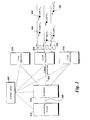
- FIG. 1 illustrates a general diagram of a power restoration system according to an exemplary embodiment for use with the system 200 shown in FIG. 2 .
- the utility control center 200 can be arranged at and/or hosted by the utility 108 and/or by any other party.
- a single utility 108, a single utility control center 200, and a small number of loads 104 are shown.
- the system can include any suitable number of utility control centers 200, utilities 108 and loads 104.
- Communication between the premise sites or loads 104, the utility control center 200, and the utility 108 occurs via a WAN (e.g., Internet) 106, WiMAX, broadband, AMI, and/or power line carriers, for example. Communication can also occur via a private network. Any suitable means for communication can be used.
- WAN e.g., Internet
- the utility control center 200 can include a Demand Response (DR) module 110, a Network Management Services (NMS) Module 130, a user interface module 132, a customer database (DB) 134, and a program database (DB) 136.
- the NMS module 130 provides communication management and provisioning for the DR module 110, the premises or loads 104 and the utility 108.
- the customer database 134 stores premise profiles for the customers in the network. Each premise profile includes data such as historical data for each premise in the network and information on participation in any demand response program, for example. The historical data can include information on customer utility usage including load type, time of use (TOU), duration of use, shed or demand response events, for example.
- TOU time of use
- the premise usage information stored in the database 134 can be updated periodically (e.g., hourly, daily) with load data, including hourly load and hourly price over a twenty four hour period, environmental data including weather information (e.g., temperature, humidity, wind speed, heating and cooling degrees, etc.) and date and time information such as day of the week, season, etc.
- the database 134 stores event data for each premise. More specifically, the database 134 stores historical information on whether a premise participated in a demand response event, the start time and end time, day of week, season, etc.
- the amount of load reduction and rebound are stored in database 134. Data related to response forecasting and expected future benefit calculations can also be stored in database 134.
- the user interface module 132 enables exchanging of information with an operator.
- the utility control center 200 further includes an energy management system (EMS) module 112 that performs load forecasting for the network, and monitors, controls, and optimizes the performance of the generation and transmission system.
- EMS energy management system
- a Supervisory Control And Data Acquisition (SCADA) module 114 provides real time information at different points in the grid and also provides local controls. SCADA usually refers to basic control and monitoring of field devices including breakers, switches, capacitors, reclosers, and transformers.
- the SCADA module 114 includes data collection computers at the control center 200 and remote terminal units (RTUs) in the field that can collectively monitor and control anywhere from hundreds to tens of thousands of data points. It also includes a user interface that is typically monitored around the clock.
- the user interface in addition to one or more computer displays, usually includes a mapboard or large group displays to provide an overview of system status.
- An Outage Management System (OMS) module 116 monitors load status information and outage restoration information for the loads 104 in the network. Some of the functions performed by the OMS module 116 include, but are not limited to, failure prediction, providing information on the extent of outages and impact to customers, and prioritizing restoration efforts. According to exemplary embodiments, the OMS module 116 includes a power restoration module 117 that manages the restoration of power to the loads 104 following an outage. The OMS module 116 operates based on a detailed network model of the distribution system that is generated and maintained by a Geographic Information Systems (GIS) module 118. A Distribution Management System (DMS) module 120 provides real-time response to adverse or unstable network conditions by providing information on load status and load response.
- GIS Geographic Information Systems
- the DMS module 120 manages the response to alarms and/or events.
- Customer information including service contract information, participation in incentive and/or demand response programs, and contract price information, for example, is monitored and controlled by the Customer Information System (CIS) module 122.
- a Direct Load Control (DLC) module 124 controls and manages customer site devices such as the thermostat - HVAC, water heater, pool pump, washer, dryer, dishwasher, LCD / Plasma TV, plug loads (e.g., computers, computer peripherals / accessories, fax machine, power supplies), refrigerator, and lighting, for example. These are mostly discrete types of devices that have on/off, eco-mode/normal mode, or multiple discrete power saving modes (e.g., dimmable lighting).
- Customer billing is performed by the billing module 126. In some embodiments, these components may be provided separately in system 100 rather than in the utility control center 200. For ease of discussion, only one utility control center 200 is shown, however, there can be any number of utility control centers as needed for performance.
- FIG. 2 illustrates a single line diagram of an overall electric system 210 from generation to utilization.
- the electric system 210 includes a generating station 212, a transmission substation 214, local substations or distribution substations 216 and loads 104.
- Generating station 212 may be any power generating station including, but not limited to, a hydropower generating station, a thermal power generating station, a wind power generating station or a solar power generating station, for example.
- Generating station 212 generates electricity at a generating station voltage.
- the electricity at transmission level voltage is transmitted to transmission substation 214 by extra high voltage (EHV) transmission lines 220.
- EHV transmission lines 220 carry electricity long distances to a substation.
- EHV extra high voltage
- HV high voltage
- the utility control center 200 is used in the system 210 for operation and maintenance of generating station 212, transmission substation 214 and distribution substation 216. Utility control center 200 receives data from each of these components and also provides control signals to these components. It should also be noted here that the loads 104 communicate with their respective local substations 216 and thus, the utility control center 200 also receives and transmits information to and from the loads 104. In one embodiment, smart meters (not shown) facilitate communication between loads 104 and local substations 216. The communication modes between these various components can include fiber optics, power line carrier systems, and various wireless technologies.
- the loads can be any type of load including, but not limited to, any type of appliances or machines, sensors, renewables, and/or plug in electric vehicles (PEV) or plug in hybrid electric vehicles (PHEV), for example.
- PEV plug in electric vehicles
- PHEV plug in hybrid electric vehicles
- some of the loads can be arranged at premises and be controlled using any number of interfaces or protocols including Zigbee, Z-Wave, WiFi, or Homeplug, for example.
- Embodiments disclosed herein provide a system and method for controlling the restoration of power or the power demand during a transient or cold load pickup condition through use of demand resources.
- the embodiments allow the loads on a distribution network to be slowly brought up to full power after an outage, so as to minimize the power drawn from the network.
- power is restored to all of the loads in distribution network simultaneously, but their power consumption is slowly ramped up so as to facilitate easy restoration of the network.
- Loads here refer to the aggregate power demand of a premise/household/commercial entity that comprises many appliances such as HVAC units, lighting, electronics, etc.
- thermostatically controlled appliances including, but not limited to, water heaters, air conditioners, and HVAC units, come online at the same time as a feeder is restored after an extended outage. These appliances operate between controlled temperature limits and under steady state conditions they cycle on and off to maintain temperature between these limits. The duty cycle of operation depends on temperature set point, temperature limits, and ambient conditions.
- thermostatic controlled appliances are present on a distribution feeder, there is enough randomization in the cycling patterns of these appliances that the overall load factor remains relatively low.
- all of the appliances will remain in the ON state until they reach their temperature set points; thus increasing the load factor on the feeder.
- the embodiments disclosed herein restore power by limiting the peak power demand on the feeder under cold load pickup, while restoring power to all the premises simultaneously. In this way, critical loads across all premises can be restored immediately, while individual, non-critical appliances within a household/entity are controlled in a way to limit the peak power demand.
- end user appliances 104 can manage their power usage to meet the constraints on the associated feeder.
- power is restored to all premises simultaneously, and individual appliances are controlled by various methods including, but not limited to, turning appliances on and off or initiating control signals including, but not limited to, voltage control or pulse width modulation (PWM) switching.
- PWM pulse width modulation
- power is restored at rated conditions to all critical appliances (i.e., lighting and other electronics, for example) simultaneously.
- Non-critical appliances i.e., water heaters, dryers, for example
- Non-critical appliances i.e., water heaters, dryers, for example
- appliances belonging to premises participating in a demand response program including, but not limited to, critical peak pricing (CPP), Variable Peak Pricing (VPP), Direct Load Control (DLC), and/or other various incentive programs, are slowly ramped up/turned on to rated conditions, while other appliances are restored immediately to rated conditions.
- CPP critical peak pricing
- VPP Variable Peak Pricing
- DLC Direct Load Control
- other various incentive programs are slowly ramped up/turned on to rated conditions, while other appliances are restored immediately to rated conditions.
- power is restored at reduced voltage.
- this technique is effective in controlling the power demand of appliances, primarily resistive loads, by initiating signals to modulate the input voltage to these appliances.
- the power drawn by a resistive appliance is proportional to the square of the applied voltage. As the voltage is increased, the power drawn by the appliance increases, and vice versa. Under a cold load pickup condition, such resistive appliances can be triggered to start at reduced voltage, which will help to reduce the power by the square of the voltage.
- the input voltage can be progressively increased to bring these appliances to normal rated conditions. This will help to reduce the peak power demand on the feeder, and at the same time assist in quickly restoring full power to other critical appliances.
- Load diversity randomizes the turning on/off of appliances and as a result the total power drawn at any instant is less than P max .
- V rated As V rated is applied to a resistive appliance, it remains in ON state till it reaches the desired steady state operating condition.
- the time taken to reach the steady state is dependent on a number of factors, such as the thermal capacity of the load, thermal conductance of the load to the surroundings/ambient, etc.
- the appliance draws P nominal power. In fact, the whole fleet of such appliances on a distribution feeder will demand P nominal until their steady state is reached.
- This strategy enables restoration of power to the non-critical appliances at a reduced voltage.
- the voltage to these appliances is increased in a controlled fashion to limit the power demand on the feeder. This can be done either by (1) grouping the appliances into different pockets (based upon their location on the feeder, for example) and increasing the voltage of pockets (which will be controlled by a step-down transformer at the appliance level), one at a time, from the reduced level to rated conditions; or (2) Initiating control signals to slowly ramp up the input voltage to all the appliances (on the feeder) simultaneously from a reduced level to intermediate level(s) and then to rated conditions. This again will be accomplished through an auto-transformer action at the appliance level. It must be noted that the utility will restore the feeder at rated voltage. The additional hardware at the appliances will help to modulate the input voltage to the appliances and consequently their power. Appliances such as HVAC units, which are sensitive to low voltage operation, will not be suitable for participation in such a cold load pickup strategy.
- FIG. 3 illustrates restoring power at reduced voltage according to an exemplary embodiment. All of the appliances are brought online at a reduced voltage of 0.5 pu. As a result, the total power demand is 0.25 * Pmax. The appliances are grouped into four load pockets. The voltage for the first 25% of the appliances is increased to the full rated voltage. As a result, there is an increase in the power demand until these appliances reach their steady state and then the power starts to fall as load diversity kicks in. The voltage to the next 25% of appliances on the feeder is then increased to the full rated voltage. Similar behavior of an initial increase and then a gradual drop in power demand is observed. Accordingly, the total power demand never reaches the Pmax value, which would be attained if all the appliances were brought online at rated conditions.
- Certain parameters should be considered including, but not limited to, starting voltage to the appliances, size of the load pocket (in terms of power demand), and time interval between load pocket pick-up (or time interval between raising the voltage level of the appliances in a pocket or on the feeder). These parameters should be designed by offline studies on a distribution feeder, taking into account the constraints on voltage, current, and power, or by any other appropriate technique. There can be variations in the settings of the control parameters. For example, instead of having just two steps of voltage, a continuously increasing function of voltage can be applied to the appliances for increasing their power gradually. Also, instead of having multiple load pockets, the power of the entire (non-critical) load can be controlled by slow ramping of the input voltage at these appliances.
- power demand is maintained within limits in cold load pickup scenarios by controlling the control saturation of a population of devices that operate using synchronized low-frequency pulse width modulation (PWM).
- PWM pulse width modulation
- This strategy can only be used on appliances that are equipped with a power electronic hardware.
- devices that operate using synchronized low-frequency PWM modulate the instantaneous demand in an on/off manner with a relatively long period (on the order of minutes, for example).
- the PWM periods of each device in the population are synchronized, which means that the frequency and start time of the PWM periods are identical.
- it is possible to adjust the saturation of the device's control input such that the maximum on-time during a given period can be reduced.
- the saturation becomes variable, the energy (i.e., average demand) can be modulated by a higher-level controller, and when all devices are synchronized, a single global variable can control the demand of the entire population.
- the saturation of each device can be controlled directly by a supervisory controller.
- the supervisory controller sends out a global signal to all of the devices specifying the saturation value.
- the saturation value is slowly ramped up, the aggregate demand will slowly increase, resulting in controlled cold load pickup
- FIG. 4 shows a flow diagram for restoring power to a distribution network according to an exemplary embodiment.
- the process 400 includes step 410, which is the start of the cold load pickup power restoration.
- step 412 the total load to be picked up on the feeder is estimated. This can be estimated through historical data and knowledge of the demographics on the feeder. For example, a lot of commercial customers would imply heavy concentration of lighting and motor loads. These parameters should be used to estimate the undiversified load demand on the feeder.
- the load limit on the feeder is determined in step 414.
- the load limit on the feeder is fixed by the electrical rating of the cables and the transformers.
- step 418 power is restored to each block simultaneously using a power restoration process including, but not limited to, demand response load control, voltage control and/or PWM switching.
- the power is restored to rated conditions to critical loads and at reduced levels to non-critical loads.
- step 422 it is determined whether the load on the feeder is at a normal feeder load level.
- the normal load level is the full diversified power demand on the feeder. This can be estimated from historical load data and weather information. If the answer in step 422 is yes, then processing continues to step 426 and no action is taken, implying that the feeder has been restored. If the answer in step 422 is no, then processing continues to step 428. In step 428, it is determined whether t > to + (i-1) ⁇ t, where i is the index that refers to group i and ⁇ t is the time interval/step before additional load is picked up on the feeder.
- step 428 This control can manifest as a load pocket being raised to rated conditions or the entire non-critical load being raised to the next intermediate level. If the answer in step 428 is no, then processing continues to step 430 and no action is taken and processing continues. If the answer in step 428 is yes, then processing continues to step 432. In step 432, additional load is picked up on the feeder. Additional load can be the next load pocket being raised to rated conditions or the entire fleet of non-critical load being ramped up to a higher (but intermediate) value. Processing then continues to step 420 until all of the groups are processed or the entire load is restored.
- the critical loads are energized to rated conditions.
- the non-critical loads are energized at reduced power levels and their power demand is managed through one of the exemplary strategies including, but not limited to, demand response load control, voltage control and/or PWM switching.
- the non-critical loads are either turned on selectively in each pocket/group to rated power via a distribution management system, or they are controlled to be picked up at reduced power via voltage control or low frequency PWM.
- the first pocket or group of non-critical loads is raised to its rated power level. Once this load pocket starts operating at its steady state, the next group of load is given full power. This process is continued until the last load pocket starts to operate at rated conditions.
- the power demand of the entire fleet of non-critical loads can be controlled to slowly ramp up from a reduced level to full rated conditions. At any point, if the power demand exceeds the feeder limit, the input power to the previous group(s) or the loads online is reduced and the whole process is repeated.
- the voltage control or PWM strategy can only be applied if the loads are capable of operating at reduced power levels.
Landscapes
- Engineering & Computer Science (AREA)
- Power Engineering (AREA)
- Supply And Distribution Of Alternating Current (AREA)
- Remote Monitoring And Control Of Power-Distribution Networks (AREA)
Applications Claiming Priority (1)
| Application Number | Priority Date | Filing Date | Title |
|---|---|---|---|
| US12/972,226 US8600573B2 (en) | 2010-12-17 | 2010-12-17 | System and method for managing cold load pickup using demand response |
Publications (2)
| Publication Number | Publication Date |
|---|---|
| EP2466714A2 true EP2466714A2 (fr) | 2012-06-20 |
| EP2466714A3 EP2466714A3 (fr) | 2015-05-27 |
Family
ID=45540739
Family Applications (1)
| Application Number | Title | Priority Date | Filing Date |
|---|---|---|---|
| EP11193577.1A Withdrawn EP2466714A3 (fr) | 2010-12-17 | 2011-12-14 | Système et procédé de gestion de capture de charge à froid utilisant une réponse de demande |
Country Status (7)
| Country | Link |
|---|---|
| US (1) | US8600573B2 (fr) |
| EP (1) | EP2466714A3 (fr) |
| JP (1) | JP2012135193A (fr) |
| AU (1) | AU2011253992B2 (fr) |
| BR (1) | BRPI1105230A2 (fr) |
| CA (1) | CA2761338A1 (fr) |
| NZ (1) | NZ597079A (fr) |
Cited By (3)
| Publication number | Priority date | Publication date | Assignee | Title |
|---|---|---|---|---|
| WO2014058969A3 (fr) * | 2012-10-11 | 2014-09-18 | Siemens Aktiengesellschaft | Utilisation d'une réaction à la demande pour permettre une planification améliorée du rétablissement de l'alimentation électrique |
| CN104868506A (zh) * | 2015-06-12 | 2015-08-26 | 中国电力科学研究院 | 一种集中式储能电站的有功出力调度方法 |
| CN110944413A (zh) * | 2019-12-06 | 2020-03-31 | 江苏智臻能源科技有限公司 | 云边协同架构下基于历史负荷辨识数据的电热细分方法 |
Families Citing this family (22)
| Publication number | Priority date | Publication date | Assignee | Title |
|---|---|---|---|---|
| US8121742B2 (en) | 2007-11-08 | 2012-02-21 | Flohr Daniel P | Methods, circuits, and computer program products for generation following load management |
| US8938311B2 (en) | 2007-11-29 | 2015-01-20 | Daniel P. Flohr | Methods of remotely managing water heating units in a water heater |
| US20100179705A1 (en) * | 2009-01-14 | 2010-07-15 | Sequentric Energy Systems, Llc | Methods, circuits, water heaters, and computer program products for remote management of separate heating elements in storage water heaters |
| EP2700061A4 (fr) | 2011-04-22 | 2014-11-19 | Expanergy Llc | Systèmes et procédés pour analyser une utilisation d'énergie |
| US9088179B2 (en) * | 2011-08-22 | 2015-07-21 | Cisco Technology, Inc. | Adaptive control of power grid operations based on energy profiles |
| EP2786337A4 (fr) * | 2011-11-28 | 2015-08-26 | Expanergy Llc | Procédés et systèmes de moteur de recherche d'énergie |
| KR101500304B1 (ko) * | 2011-12-26 | 2015-03-11 | 주식회사 케이티 | 에너지 저장장치의 충방전 제어 방법 및 시스템 |
| US9502898B2 (en) * | 2012-02-01 | 2016-11-22 | General Electric Company | Systems and methods for managing a power distribution system |
| CA2778345C (fr) | 2012-06-01 | 2013-08-20 | Bipco-Soft R3 Inc. | Regulateur de puissance |
| US8897632B2 (en) * | 2012-10-17 | 2014-11-25 | Daniel P. Flohr | Methods of remotely managing water heating units in a water heater and related water heaters |
| US9250618B2 (en) | 2013-01-29 | 2016-02-02 | General Electric Company | PWM based energy management with local distributed transformer constraints |
| JP5935024B2 (ja) | 2013-06-28 | 2016-06-15 | パナソニックIpマネジメント株式会社 | 電力分配制御装置及び電力分配制御方法 |
| JP2015076931A (ja) * | 2013-10-07 | 2015-04-20 | 株式会社日立製作所 | 電力需要調整システム、電力需要調整方法および電力管理装置 |
| JP6238023B2 (ja) * | 2014-05-21 | 2017-11-29 | パナソニックIpマネジメント株式会社 | 電力制御方法、電力制御装置、及び、電力制御システム |
| CN105717355A (zh) * | 2014-07-11 | 2016-06-29 | 英科德技术股份有限公司 | 用于能量测量的装置、服务器、系统和方法 |
| US20160241031A1 (en) * | 2015-02-18 | 2016-08-18 | Nec Laboratories America, Inc. | Dynamic probability-based power outage management system |
| WO2018144009A1 (fr) * | 2017-02-03 | 2018-08-09 | Duke Energy Corporation | Procédés de gestion de puissance pour un circuit d'une sous-station et appareils et produits-programmes d'ordinateur associés |
| CA3051063C (fr) | 2017-02-15 | 2022-04-05 | Simon Jasmin | Dispositif de commande de puissance |
| US10483754B2 (en) * | 2017-05-01 | 2019-11-19 | Abb Schweiz Ag | Fault detection and location in nested microgrids |
| CN111489091A (zh) * | 2020-04-14 | 2020-08-04 | 广东电网有限责任公司广州供电局 | 一种电力系统恢复力综合评价方法 |
| KR102520871B1 (ko) * | 2020-10-06 | 2023-04-12 | 아주대학교산학협력단 | 전압 저감 기반의 계통 복구 장치 및 방법 |
| WO2024077187A1 (fr) * | 2022-10-07 | 2024-04-11 | Landis+Gyr Technology, Inc. | Compteur électrique et procédé de gestion de prise de charge froide |
Family Cites Families (9)
| Publication number | Priority date | Publication date | Assignee | Title |
|---|---|---|---|---|
| US3129358A (en) | 1959-10-20 | 1964-04-14 | Westinghouse Electric Corp | Cold load pick-up apparatus for an automatic recloser |
| EP0003010A1 (fr) | 1977-12-27 | 1979-07-11 | United Technologies Corporation | Procédé et appareil pour limiter la consommation d'énergie en chauffage, ventilation et conditionnement d'air |
| US4402059A (en) | 1981-04-09 | 1983-08-30 | Westinghouse Electric Corp. | Load management terminal |
| US5572438A (en) | 1995-01-05 | 1996-11-05 | Teco Energy Management Services | Engery management and building automation system |
| US5973899A (en) | 1998-09-10 | 1999-10-26 | Pacificorp | Automated power feeder restoration system and method |
| US6747368B2 (en) * | 2001-08-30 | 2004-06-08 | Harold M. Jarrett, Jr. | Wireless control of power transfer switches for electrical load management |
| US7242114B1 (en) | 2003-07-08 | 2007-07-10 | Cannon Technologies, Inc. | Thermostat device with line under frequency detection and load shedding capability |
| US7265957B2 (en) | 2004-06-18 | 2007-09-04 | Cooper Technologies Company | Restoring electrical load to distribution feeder circuits |
| US7509188B2 (en) * | 2007-01-16 | 2009-03-24 | At&T Intellectual Property, I,L.P. | Methods, systems, computer products and website for power maintenance and restoration |
-
2010
- 2010-12-17 US US12/972,226 patent/US8600573B2/en not_active Expired - Fee Related
-
2011
- 2011-12-08 CA CA2761338A patent/CA2761338A1/fr not_active Abandoned
- 2011-12-13 AU AU2011253992A patent/AU2011253992B2/en not_active Expired - Fee Related
- 2011-12-13 NZ NZ597079A patent/NZ597079A/xx not_active IP Right Cessation
- 2011-12-14 EP EP11193577.1A patent/EP2466714A3/fr not_active Withdrawn
- 2011-12-14 BR BRPI1105230-9A patent/BRPI1105230A2/pt not_active IP Right Cessation
- 2011-12-14 JP JP2011272886A patent/JP2012135193A/ja active Pending
Non-Patent Citations (1)
| Title |
|---|
| None |
Cited By (7)
| Publication number | Priority date | Publication date | Assignee | Title |
|---|---|---|---|---|
| WO2014058969A3 (fr) * | 2012-10-11 | 2014-09-18 | Siemens Aktiengesellschaft | Utilisation d'une réaction à la demande pour permettre une planification améliorée du rétablissement de l'alimentation électrique |
| CN105144542A (zh) * | 2012-10-11 | 2015-12-09 | 西门子公司 | 使用需求响应以启用改进的电力供给恢复规划 |
| US9553455B2 (en) | 2012-10-11 | 2017-01-24 | Siemens Aktiengesellschaft | Use of demand response to enable improved power supply restoration planning |
| CN104868506A (zh) * | 2015-06-12 | 2015-08-26 | 中国电力科学研究院 | 一种集中式储能电站的有功出力调度方法 |
| CN104868506B (zh) * | 2015-06-12 | 2018-01-19 | 中国电力科学研究院 | 一种集中式储能电站的有功出力调度方法 |
| CN110944413A (zh) * | 2019-12-06 | 2020-03-31 | 江苏智臻能源科技有限公司 | 云边协同架构下基于历史负荷辨识数据的电热细分方法 |
| CN110944413B (zh) * | 2019-12-06 | 2021-08-10 | 江苏智臻能源科技有限公司 | 云边协同架构下基于历史负荷辨识数据的电热细分方法 |
Also Published As
| Publication number | Publication date |
|---|---|
| NZ597079A (en) | 2013-06-28 |
| JP2012135193A (ja) | 2012-07-12 |
| BRPI1105230A2 (pt) | 2013-04-09 |
| AU2011253992B2 (en) | 2015-09-10 |
| US20120158198A1 (en) | 2012-06-21 |
| EP2466714A3 (fr) | 2015-05-27 |
| AU2011253992A1 (en) | 2012-07-05 |
| US8600573B2 (en) | 2013-12-03 |
| CA2761338A1 (fr) | 2012-06-17 |
Similar Documents
| Publication | Publication Date | Title |
|---|---|---|
| US8600573B2 (en) | System and method for managing cold load pickup using demand response | |
| US8744638B2 (en) | Method and system for demand response in a distribution network | |
| US11106228B2 (en) | Thermal energy storage apparatus, controllers and thermal energy storage control methods | |
| JP5710028B2 (ja) | 能動負荷管理の使用を通じて配分可能な運転用予備力エネルギーキャパシティを推定及び供給するシステム及び方法 | |
| USRE48795E1 (en) | System and method for controlling an electricity supply | |
| CA2777147C (fr) | Redemarrage commande de service electrique a l'interieur d'une zone de service public | |
| EP2378483A1 (fr) | Système et procédé de planification d'événements de réponse de demande dans un réseau | |
| AU2011279543B2 (en) | Method for planning and/or controlling an energy output to a consumer and/or an energy supply to an energy distribution network | |
| KR20120016133A (ko) | 능동 부하 관리를 이용한 급송가능 운영 예비 에너지 용량의 추정 및 제공 시스템 및 방법 | |
| EP2503503A1 (fr) | Systèmes et procédés pour générer une facture d'électricité | |
| EP2503504A1 (fr) | Systèmes et procédés pour générer une facture | |
| EP3574560B1 (fr) | Techniques de gestion de la consommation de ressources pour un mesurage basé sur la demande | |
| AU2019239701B2 (en) | System for frequency regulation on a power distribution network | |
| AU2019239703B2 (en) | System for controlling power consumption on a distribution grid | |
| JP2016025681A (ja) | 集合住宅節電システム |
Legal Events
| Date | Code | Title | Description |
|---|---|---|---|
| PUAI | Public reference made under article 153(3) epc to a published international application that has entered the european phase |
Free format text: ORIGINAL CODE: 0009012 |
|
| AK | Designated contracting states |
Kind code of ref document: A2 Designated state(s): AL AT BE BG CH CY CZ DE DK EE ES FI FR GB GR HR HU IE IS IT LI LT LU LV MC MK MT NL NO PL PT RO RS SE SI SK SM TR |
|
| AX | Request for extension of the european patent |
Extension state: BA ME |
|
| PUAL | Search report despatched |
Free format text: ORIGINAL CODE: 0009013 |
|
| AK | Designated contracting states |
Kind code of ref document: A3 Designated state(s): AL AT BE BG CH CY CZ DE DK EE ES FI FR GB GR HR HU IE IS IT LI LT LU LV MC MK MT NL NO PL PT RO RS SE SI SK SM TR |
|
| AX | Request for extension of the european patent |
Extension state: BA ME |
|
| RIC1 | Information provided on ipc code assigned before grant |
Ipc: H02J 3/00 20060101ALI20150422BHEP Ipc: H02J 13/00 20060101ALI20150422BHEP Ipc: H02J 3/48 20060101ALI20150422BHEP Ipc: H02J 3/14 20060101AFI20150422BHEP |
|
| STAA | Information on the status of an ep patent application or granted ep patent |
Free format text: STATUS: THE APPLICATION IS DEEMED TO BE WITHDRAWN |
|
| 18D | Application deemed to be withdrawn |
Effective date: 20151128 |