EP2466647A2 - Dye-sensitive solar cell and module consisting of same - Google Patents
Dye-sensitive solar cell and module consisting of same Download PDFInfo
- Publication number
- EP2466647A2 EP2466647A2 EP10808300A EP10808300A EP2466647A2 EP 2466647 A2 EP2466647 A2 EP 2466647A2 EP 10808300 A EP10808300 A EP 10808300A EP 10808300 A EP10808300 A EP 10808300A EP 2466647 A2 EP2466647 A2 EP 2466647A2
- Authority
- EP
- European Patent Office
- Prior art keywords
- solar cell
- dye
- sensitized solar
- electrolyte
- beads
- Prior art date
- Legal status (The legal status is an assumption and is not a legal conclusion. Google has not performed a legal analysis and makes no representation as to the accuracy of the status listed.)
- Withdrawn
Links
Images



Classifications
-
- H—ELECTRICITY
- H01—ELECTRIC ELEMENTS
- H01G—CAPACITORS; CAPACITORS, RECTIFIERS, DETECTORS, SWITCHING DEVICES, LIGHT-SENSITIVE OR TEMPERATURE-SENSITIVE DEVICES OF THE ELECTROLYTIC TYPE
- H01G9/00—Electrolytic capacitors, rectifiers, detectors, switching devices, light-sensitive or temperature-sensitive devices; Processes of their manufacture
- H01G9/20—Light-sensitive devices
- H01G9/2004—Light-sensitive devices characterised by the electrolyte, e.g. comprising an organic electrolyte
-
- H—ELECTRICITY
- H10—SEMICONDUCTOR DEVICES; ELECTRIC SOLID-STATE DEVICES NOT OTHERWISE PROVIDED FOR
- H10F—INORGANIC SEMICONDUCTOR DEVICES SENSITIVE TO INFRARED RADIATION, LIGHT, ELECTROMAGNETIC RADIATION OF SHORTER WAVELENGTH OR CORPUSCULAR RADIATION
- H10F10/00—Individual photovoltaic cells, e.g. solar cells
-
- H—ELECTRICITY
- H01—ELECTRIC ELEMENTS
- H01G—CAPACITORS; CAPACITORS, RECTIFIERS, DETECTORS, SWITCHING DEVICES, LIGHT-SENSITIVE OR TEMPERATURE-SENSITIVE DEVICES OF THE ELECTROLYTIC TYPE
- H01G9/00—Electrolytic capacitors, rectifiers, detectors, switching devices, light-sensitive or temperature-sensitive devices; Processes of their manufacture
- H01G9/20—Light-sensitive devices
- H01G9/2027—Light-sensitive devices comprising an oxide semiconductor electrode
- H01G9/2031—Light-sensitive devices comprising an oxide semiconductor electrode comprising titanium oxide, e.g. TiO2
-
- H—ELECTRICITY
- H01—ELECTRIC ELEMENTS
- H01G—CAPACITORS; CAPACITORS, RECTIFIERS, DETECTORS, SWITCHING DEVICES, LIGHT-SENSITIVE OR TEMPERATURE-SENSITIVE DEVICES OF THE ELECTROLYTIC TYPE
- H01G9/00—Electrolytic capacitors, rectifiers, detectors, switching devices, light-sensitive or temperature-sensitive devices; Processes of their manufacture
- H01G9/20—Light-sensitive devices
- H01G9/2059—Light-sensitive devices comprising an organic dye as the active light absorbing material, e.g. adsorbed on an electrode or dissolved in solution
-
- Y—GENERAL TAGGING OF NEW TECHNOLOGICAL DEVELOPMENTS; GENERAL TAGGING OF CROSS-SECTIONAL TECHNOLOGIES SPANNING OVER SEVERAL SECTIONS OF THE IPC; TECHNICAL SUBJECTS COVERED BY FORMER USPC CROSS-REFERENCE ART COLLECTIONS [XRACs] AND DIGESTS
- Y02—TECHNOLOGIES OR APPLICATIONS FOR MITIGATION OR ADAPTATION AGAINST CLIMATE CHANGE
- Y02A—TECHNOLOGIES FOR ADAPTATION TO CLIMATE CHANGE
- Y02A30/00—Adapting or protecting infrastructure or their operation
- Y02A30/60—Planning or developing urban green infrastructure
-
- Y—GENERAL TAGGING OF NEW TECHNOLOGICAL DEVELOPMENTS; GENERAL TAGGING OF CROSS-SECTIONAL TECHNOLOGIES SPANNING OVER SEVERAL SECTIONS OF THE IPC; TECHNICAL SUBJECTS COVERED BY FORMER USPC CROSS-REFERENCE ART COLLECTIONS [XRACs] AND DIGESTS
- Y02—TECHNOLOGIES OR APPLICATIONS FOR MITIGATION OR ADAPTATION AGAINST CLIMATE CHANGE
- Y02B—CLIMATE CHANGE MITIGATION TECHNOLOGIES RELATED TO BUILDINGS, e.g. HOUSING, HOUSE APPLIANCES OR RELATED END-USER APPLICATIONS
- Y02B10/00—Integration of renewable energy sources in buildings
- Y02B10/10—Photovoltaic [PV]
-
- Y—GENERAL TAGGING OF NEW TECHNOLOGICAL DEVELOPMENTS; GENERAL TAGGING OF CROSS-SECTIONAL TECHNOLOGIES SPANNING OVER SEVERAL SECTIONS OF THE IPC; TECHNICAL SUBJECTS COVERED BY FORMER USPC CROSS-REFERENCE ART COLLECTIONS [XRACs] AND DIGESTS
- Y02—TECHNOLOGIES OR APPLICATIONS FOR MITIGATION OR ADAPTATION AGAINST CLIMATE CHANGE
- Y02E—REDUCTION OF GREENHOUSE GAS [GHG] EMISSIONS, RELATED TO ENERGY GENERATION, TRANSMISSION OR DISTRIBUTION
- Y02E10/00—Energy generation through renewable energy sources
- Y02E10/50—Photovoltaic [PV] energy
- Y02E10/542—Dye sensitized solar cells
-
- Y—GENERAL TAGGING OF NEW TECHNOLOGICAL DEVELOPMENTS; GENERAL TAGGING OF CROSS-SECTIONAL TECHNOLOGIES SPANNING OVER SEVERAL SECTIONS OF THE IPC; TECHNICAL SUBJECTS COVERED BY FORMER USPC CROSS-REFERENCE ART COLLECTIONS [XRACs] AND DIGESTS
- Y02—TECHNOLOGIES OR APPLICATIONS FOR MITIGATION OR ADAPTATION AGAINST CLIMATE CHANGE
- Y02P—CLIMATE CHANGE MITIGATION TECHNOLOGIES IN THE PRODUCTION OR PROCESSING OF GOODS
- Y02P70/00—Climate change mitigation technologies in the production process for final industrial or consumer products
- Y02P70/50—Manufacturing or production processes characterised by the final manufactured product
Definitions
- the present invention relates to a dye-sensitized solar cell and a module using the same and more particularly, to a dye-sensitized solar cell wherein light passing through a photoelectrode substrate is refracted or reflected by optical beads, and irradiated onto the photoelectrode substrate, thereby to improve the efficiency of the solar cell; particularly, the efficiency of a dye-sensitized solar cell for a BIPV system is more effectively improved, said solar cell not having a separate scattering layer for maintaining the translucency thereof; and if the optical beads are colored, solar cells with a variety of colors can be obtained, which achieves an aesthetic enhancement for a building adopting the BIPV system, and a module using the same.
- the dye-sensitized solar cell is a photoelectrochemical solar cell mainly comprising a dye molecule capable of absorbing visible rays to generate an electron-hole pair, and a transition metal oxide for transmitting the generated electrons.
- a unit cell for a dye-sensitized solar cell comprises, as a basic structure, transparent top and bottom substrates, and conductive transparent electrodes each formed on the surfaces of the transparent substrates, wherein on one conductive transparent electrode, which corresponds to a photoelectrode (first electrode), a transition metal oxide multi-porous layer adsorbed with a dye on the surface thereof is formed; on the other conductive transparent electrode, which corresponds to a catalyst electrode (second electrode), a catalyst thin-film electrode is formed; the transition metal oxide, for example, TiO 2 multi-porous electrode and the catalyst thin-film electrode are spaced apart by a certain gap to form space, which is filled with an electrolyte; and the gap is enclosed by an encapsulating material to store the electrolyte.
- Photovoltaic energy generates electricity and provides it to consumers.
- Building-integrated photovoltaic modules have been used as building windows or exterior materials to reduce construction costs, to enable the buildings themselves to generate power, and to raise the value of the buildings due to their environment-friendly design nature.
- the dye-sensitized solar cells that are applied to a BIPV (Building Integrated PhotoVoltaic) system do not add the scattering layer during the preparation thereof so as to function as building windows that are transparent, and their photoelectric conversion efficiency is thus decreased.
- the present invention provides a dye-sensitized solar cell in which a photoelectrode substrate and a catalyst electrode substrate are spaced apart from each other by a separating space and coupled together by an encapsulating material and the separating space is filled with an electrolyte, characterized in that the electrolyte contains optical beads.
- the invention provides a dye-sensitized solar cell in which a photoelectrode substrate and a catalyst electrode substrate are spaced apart from each other by a separating space and coupled together by an encapsulating material and the separating space is filled with an electrolyte, characterized by further comprising a scattering layer formed by coating a paste containing optical bead onto the side of the photoelectrode substrate facing the separating space.
- the present invention provides a dye-sensitized solar cell module formed by integrating the dye-sensitized solar cell.
- the dye-sensitized solar cell and the module using the same of the present invention light passing through the photoelectrode substrate is refracted or reflected by the optical beads, and irradiated onto the photoelectrode substrate, thereby to improve the efficiency of the solar cell; particularly, the efficiency of a dye-sensitized solar cell for a BIPV system is more effectively improved, said solar cell not having a separate scattering layer for maintaining the translucency thereof; and if the optical beads are colored, solar cells with a variety of colors can be obtained, which achieves an aesthetic enhancement for a building adopting the BIPV system.
- beads having a variety of sizes may be used, they may be chosen to function as a spacer for maintaining a certain interval between the top substrate and the bottom substrate as the size of modules is increased.
- the manufacturing of dye-sensitized solar cells involved a sintering process of 500°C or above TiO 2 to form a scattering layer of about 300-400 nm size in order to increase the photoelectric conversion efficiency thereof and it required the use of expensive materials.
- the present invention utilizes as a material for the scattering layer inexpensive optical beads that have been already massively produced, and thus it can reduce manufacturing costs.
- a paste capable of forming optical beads at temperatures not higher than 300 °C can be prepared and coated.
- film formation is carried out at low temperatures compared to the existing technique, a bending issue of glass substrates is remarkably improved.
- the existing dye-sensitized solar cells are characterized in that they could express several colors, such various color expression was not possible with maintaining the same properties.
- the present invention enables to express various colors without change in efficiency.
- the dye-sensitized solar cell of the present invention comprises a photoelectrode substrate (10a + 20) and a catalyst substrate (10b + 30) which are spaced apart from each other by a separating space and coupled together by an encapsulating material (50), and an electrolyte (40) which is filled in the separating space, wherein the electrolyte (40) contains optical beads (60).
- the dye-sensitized solar cell of the present invention is configured such that a photoelectrode substrate (10a + 20) and a catalyst substrate (10b + 30) are spaced apart from each other by a separating space and coupled together by an encapsulating material (50), and the separating space is filled with an electrolyte (40), and it may include any common dye-sensitized solar cells or a dye-sensitized solar cell applied to a BIPV system.
- the electrolyte contains optical beads (60), and its specific embodiments are as shown in Fig. 1 to Fig. 3 .
- the electrolyte may be a liquid electrolyte, gel phase electrolyte, polymer solid electrolyte, inorganic solid electrolyte, etc. and preferably, it may be a liquid electrolyte to secure transparency in dye-sensitized solar cells for a BIPV system.
- the optical beads are dispersed in the electrolyte. As shown in Fig.
- this reabsorption process may help enhance the efficiency (in Fig. 4 , the left part illustrates a reabsorption process induced by reflection, and the right part illustrates a reabsorption process induced by refraction).
- the optical beads help enhance the efficiency by reflecting or refracting the light which is incident onto the dye-sensitized solar cell and then incident onto the optical beads, toward the photoelectrode substrate.
- the optical beads in the case of a liquid electrolyte, may be included in an electrolyte solution by blending with the electrolyte before or after the injection of the electrolyte, or in the case of other solid phase or gel phase, they may be dispersed in the solid phase or gel phase by mixing them together during the preparation thereof.
- the size of the optical beads may be equal as shown in Fig. 1 , or they may be used in combination of a variety of beads in terms of size and shape (sphere, oval, polyhedron, cylinder, polyprism, etc.).
- the beads may have diameters of 30 ⁇ m to 100 ⁇ m.
- the optical beads may be concentrated on the bottom if the dye-sensitized solar cell containing the liquid phase electrolyte is disposed in its standing position. Therefore, in order to prevent this happening and make reflection or refraction occur evenly, the beads may be constituted as the following configuration.
- the total volume of the optical beads may be preferably at least 70% of the space to be filled with the electrolyte.
- the total volume of the optical beads as used herein refers to a volume comprising the net volume of the optical beads and the gap volume between them. The beads filled by this volume, even in the case that the beads are concentrated on the bottom, enable comparatively even reflection or refraction throughout the entire area to be obtained, thereby increasing the efficiency improvement effects and reducing the charge amount of the electrolyte without affecting the efficiency thereof.
- the diameter of the optical beads may be preferably at least 70% of the direction interval (a) between the photoelectrode substrate and the catalyst electrode substrate in the space to be filled with the electrolyte.
- the beads having such a large size may remarkably reduce the cornering problems of the beads to the bottom caused by the stacking thereof, and enable comparatively even reflection or refraction throughout the entire area to be obtained, thereby increasing the efficiency improvement effects.
- the specific gravity of the optical beads may be adjusted to be identical to the specific gravity of the electrolyte so that the optical beads may be evenly dispersed without being concentrated either on the top or bottom.
- the optical beads may be constructed to have a hollow part in the center of them, or the concentration of the electrolyte solution may be adjusted.
- the optical beads may perform as a spacer for maintaining the interval between the two substrates.
- the diameter of the optical beads may be preferably at least 70% of the direction interval (a) between the photoelectrode substrate and the catalyst electrode substrate in the space to be filled with the electrolyte.
- the optical beads may be any particles in any shapes as long as they are stable in electrolytes and are able to reflect or refract light and preferably, they may be those particles having a high reflection rate or high refraction rate.
- Their specific examples may include glass beads, PMMA beads, melamine resin beads, glass beads coated with substances that are stable in electrolyte and have a high reflection rate, such as platinum or gold, PMMA beads coated with substances that are stable in electrolyte and have a high reflection rate, such as platinum or gold, melamine resin beads coated with substances that are stable in electrolyte and have a high reflection rate, such as platinum or gold, ceramic beads coated with substances that are stable in electrolyte and have a high reflection rate, such as platinum or gold, metal beads coated with substances that are stable in electrolyte and have a high reflection rate, such as platinum or gold, and so on, and preferably, such beads may be colored to express a variety of colors in case that the dye-sensitized solar cell is applied to a transparent dye-
- the optical beads may be OPTBEADS (registered trademark) by Nissan Chemical Industries, Ltd.
- the OPTBEADS according to its disclosure, has a structure of a spherical body of melamine resins in the inside, of which the surface is thinly coated with silica and the outer surface of which is then coated again with melamine resins, and it has a high refraction rate of about 1.65 and thus induces re-incident of incident light onto the photoelectrode.
- the melamine resins of the optical beads OPTBEAD by Nissan Chemical Industries, Ltd may be further colored to express a variety of colors.
- the present invention provides, as an efficiency improvement method using the optical beads, a dye-sensitized solar cell in which a photoelectrode substrate and a catalyst electrode substrate are spaced apart from each other by a separating space and coupled together by an encapsulating material and the separating space is filled with an electrolyte, characterized by further comprising a scattering layer (70) formed by coating a paste containing optical beads (60) onto the side of the photoelectrode substrate facing the separating space.
- a dye-sensitized solar cell may add a scattering layer on the side of the photoelectrode substrate facing the separating space (that is, the hidden side of the photoelectrode substrate).
- a TiO 2 scattering layer of 300 ⁇ 400 nm size is generally formed, but it involves the coating of expensive materials such as titanium dioxide and a sintering process at high temperatures of 500 °C or above.
- the paste dispersed with the optical beads as in the present invention is coated, it is possible to form a scattering layer at a low temperature with low cost, thereby to remarkably improve a bending issue of the glass substrates.
- FIG. 5 A specific example of the dye-sensitized solar cell with the scattering layer formed therein is as shown in Fig. 5 , and the efficiency improvement mechanism thereof is shown in Fig. 6 .
- the left part illustrates a reabsorption process induced by reflection
- the right part illustrates a reabsorption process induced by reflection.
- optical beads as used herein may be the same as the beads described in the above, and they may be colored as well to express a variety of colors of the scattering layer.
- the present invention provides a dye-sensitized solar cell module formed by integrating the dye-sensitized solar cell as described in the above and preferably, the dye-sensitized solar cell module formed by integrating the dye-sensitized solar cell may be applied to a BIPV system.
- the present invention may be applied to all the conventional dye-sensitized solar cell modules, efficiency improvement by the optical beads is remarkable particularly in the transparent dye-sensitized solar cell modules having no scattering layer for BIPV systems. It is to be understood that the integration of the dye-sensitized solar cells to the modules may be performed using ordinary methods and structures.
Landscapes
- Engineering & Computer Science (AREA)
- Power Engineering (AREA)
- Chemical & Material Sciences (AREA)
- Chemical Kinetics & Catalysis (AREA)
- Electrochemistry (AREA)
- Microelectronics & Electronic Packaging (AREA)
- Photovoltaic Devices (AREA)
- Hybrid Cells (AREA)
Abstract
Description
- The present invention relates to a dye-sensitized solar cell and a module using the same and more particularly, to a dye-sensitized solar cell wherein light passing through a photoelectrode substrate is refracted or reflected by optical beads, and irradiated onto the photoelectrode substrate, thereby to improve the efficiency of the solar cell; particularly, the efficiency of a dye-sensitized solar cell for a BIPV system is more effectively improved, said solar cell not having a separate scattering layer for maintaining the translucency thereof; and if the optical beads are colored, solar cells with a variety of colors can be obtained, which achieves an aesthetic enhancement for a building adopting the BIPV system, and a module using the same.
- Since a dye-sensitized nanoparticle titanium oxide solar cell was developed by Michael Gratzel et al. of Swiss Federal Institute of Technology Lausanne (EPFL) in 1991, many studies on this field are under progress. As the dye-sensitized solar cell has remarkably low manufacturing costs compared to the existing silicon solar cells, it has a potential of replacing the existing amorphous silicon solar cells. Unlike the silicon solar cells, the dye-sensitized solar cell is a photoelectrochemical solar cell mainly comprising a dye molecule capable of absorbing visible rays to generate an electron-hole pair, and a transition metal oxide for transmitting the generated electrons.
- Generally, a unit cell for a dye-sensitized solar cell comprises, as a basic structure, transparent top and bottom substrates, and conductive transparent electrodes each formed on the surfaces of the transparent substrates, wherein on one conductive transparent electrode, which corresponds to a photoelectrode (first electrode), a transition metal oxide multi-porous layer adsorbed with a dye on the surface thereof is formed; on the other conductive transparent electrode, which corresponds to a catalyst electrode (second electrode), a catalyst thin-film electrode is formed; the transition metal oxide, for example, TiO2 multi-porous electrode and the catalyst thin-film electrode are spaced apart by a certain gap to form space, which is filled with an electrolyte; and the gap is enclosed by an encapsulating material to store the electrolyte.
- In case of general dye-sensitized solar cells, transparency is not required for the installation of solar cells. Therefore, in order to increase the efficiency of the solar cells, it is common to have a scattering layer on the side of the photoelectrode substrate facing the separating space (corresponding to the back side of the photoelectrode substrate), which functions as sending light passing through the photoelectrode substrate back to the photoelectrode substrate.
- Photovoltaic energy generates electricity and provides it to consumers. Building-integrated photovoltaic modules have been used as building windows or exterior materials to reduce construction costs, to enable the buildings themselves to generate power, and to raise the value of the buildings due to their environment-friendly design nature. The dye-sensitized solar cells that are applied to a BIPV (Building Integrated PhotoVoltaic) system do not add the scattering layer during the preparation thereof so as to function as building windows that are transparent, and their photoelectric conversion efficiency is thus decreased.
- Furthermore, even in case of the modules which do not require transparency, they use an expensive TiO2 scattering layer and thus increase raw material costs. In addition, the preparation of the scattering layer involves a complicated process.
- Therefore, there are demands on the development of a dye-sensitized solar cell capable of addressing the above problems and a solar cell module using it.
- Accordingly, it is an object of the invention to provide a dye-sensitized solar cell wherein light passing through a photoelectrode substrate is refracted or reflected by optical beads, and irradiated onto the photoelectrode substrate, thereby to improve the efficiency of the solar cell; particularly, the efficiency of a dye-sensitized solar cell for a BIPV system is more effectively improved, said solar cell not having a separate scattering layer for maintaining the translucency thereof; and if the optical beads are colored, solar cells with a variety of colors can be obtained, which achieves an aesthetic enhancement for a building adopting the BIPV system, and a module using the same.
- In order to achieve the objects, the present invention provides a dye-sensitized solar cell in which a photoelectrode substrate and a catalyst electrode substrate are spaced apart from each other by a separating space and coupled together by an encapsulating material and the separating space is filled with an electrolyte, characterized in that the electrolyte contains optical beads.
- Also, the invention provides a dye-sensitized solar cell in which a photoelectrode substrate and a catalyst electrode substrate are spaced apart from each other by a separating space and coupled together by an encapsulating material and the separating space is filled with an electrolyte, characterized by further comprising a scattering layer formed by coating a paste containing optical bead onto the side of the photoelectrode substrate facing the separating space.
- Further, the present invention provides a dye-sensitized solar cell module formed by integrating the dye-sensitized solar cell.
- According to the dye-sensitized solar cell and the module using the same of the present invention, light passing through the photoelectrode substrate is refracted or reflected by the optical beads, and irradiated onto the photoelectrode substrate, thereby to improve the efficiency of the solar cell; particularly, the efficiency of a dye-sensitized solar cell for a BIPV system is more effectively improved, said solar cell not having a separate scattering layer for maintaining the translucency thereof; and if the optical beads are colored, solar cells with a variety of colors can be obtained, which achieves an aesthetic enhancement for a building adopting the BIPV system.
- In the past, where transparent dye-sensitized solar cells were manufactured, efficiency increase had limitations because a large amount of light passed through. However, if optical beads are sprinkled and dispersed in the space filled with the electrolyte solution in the present invention, they increase the amount of light that dye molecules encounter by scattering light that affects the efficiency and dies, while not having significant influences on transparency, thereby to cause the efficiency increase.
- Also, since beads having a variety of sizes may be used, they may be chosen to function as a spacer for maintaining a certain interval between the top substrate and the bottom substrate as the size of modules is increased.
- Further, in the past, the manufacturing of dye-sensitized solar cells involved a sintering process of 500°C or above TiO2 to form a scattering layer of about 300-400 nm size in order to increase the photoelectric conversion efficiency thereof and it required the use of expensive materials. However, the present invention utilizes as a material for the scattering layer inexpensive optical beads that have been already massively produced, and thus it can reduce manufacturing costs. For the formation of the scattering layer to increase scattering effects, a paste capable of forming optical beads at temperatures not higher than 300 °C can be prepared and coated. Thus, as film formation is carried out at low temperatures compared to the existing technique, a bending issue of glass substrates is remarkably improved.
- Although the existing dye-sensitized solar cells are characterized in that they could express several colors, such various color expression was not possible with maintaining the same properties. However, in the present invention, it is possible to adsorb a variety of colors to melamine resins in the optical beads, without altering main dyes that determine the efficiency. Thus, as the color of the scattering layer formed on the back side or the electrolyte is adjustable, the present invention enables to express various colors without change in efficiency.
-
-
Fig. 1 is a schematic cross-sectional view illustrating one embodiment of a dye-sensitized solar cell containing optical beads according to the present invention. -
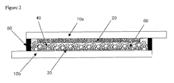
Fig. 2 is a schematic cross-sectional view illustrating another embodiment of a dye-sensitized solar cell containing optical beads according to the present invention. -
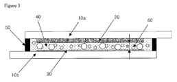
Fig. 3 is a schematic cross-sectional view illustrating another embodiment of a dye-sensitized solar cell containing optical beads according to the present invention. -
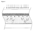
Fig. 4 is an enlarged view of a dye-sensitized solar cell containing optical beads according to the present invention, schematically illustrating the mechanism of the optical beads inside the electrolyte. -
Fig. 5 is a schematic cross-sectional view illustrating one embodiment of a dye-sensitized solar cell containing optical beads according to the present invention, which comprises a scattering layer containing the optical beads. -
Fig. 6 is an enlarged view of a dye-sensitized solar cell containing optical beads according to the present invention, which comprises a scattering layer containing the optical beads, schematically illustrating the mechanism of the optical beads inside in the scattering layer. - Hereinafter, the present invention is described in detail.
- The dye-sensitized solar cell of the present invention comprises a photoelectrode substrate (10a + 20) and a catalyst substrate (10b + 30) which are spaced apart from each other by a separating space and coupled together by an encapsulating material (50), and an electrolyte (40) which is filled in the separating space, wherein the electrolyte (40) contains optical beads (60).
- A detailed description regarding each component will be made with reference to the drawings.
- The dye-sensitized solar cell of the present invention is configured such that a photoelectrode substrate (10a + 20) and a catalyst substrate (10b + 30) are spaced apart from each other by a separating space and coupled together by an encapsulating material (50), and the separating space is filled with an electrolyte (40), and it may include any common dye-sensitized solar cells or a dye-sensitized solar cell applied to a BIPV system.
- The electrolyte contains optical beads (60), and its specific embodiments are as shown in
Fig. 1 to Fig. 3 . Thus, the electrolyte may be a liquid electrolyte, gel phase electrolyte, polymer solid electrolyte, inorganic solid electrolyte, etc. and preferably, it may be a liquid electrolyte to secure transparency in dye-sensitized solar cells for a BIPV system. The optical beads are dispersed in the electrolyte. As shown inFig. 4 , some of light that is incident onto a dye-sensitized solar cell is absorbed to the photoelectrode substrate, and light that is not absorbed and passes through is reflected or refracted by the optical beads, and then irradiated back onto the photoelectrode substrate. Thus, this reabsorption process may help enhance the efficiency (inFig. 4 , the left part illustrates a reabsorption process induced by reflection, and the right part illustrates a reabsorption process induced by refraction). In other words, the optical beads help enhance the efficiency by reflecting or refracting the light which is incident onto the dye-sensitized solar cell and then incident onto the optical beads, toward the photoelectrode substrate. - The optical beads, in the case of a liquid electrolyte, may be included in an electrolyte solution by blending with the electrolyte before or after the injection of the electrolyte, or in the case of other solid phase or gel phase, they may be dispersed in the solid phase or gel phase by mixing them together during the preparation thereof. The size of the optical beads may be equal as shown in
Fig. 1 , or they may be used in combination of a variety of beads in terms of size and shape (sphere, oval, polyhedron, cylinder, polyprism, etc.). Preferably, the beads may have diameters of 30 µm to 100 µm. - Meanwhile, the optical beads may be concentrated on the bottom if the dye-sensitized solar cell containing the liquid phase electrolyte is disposed in its standing position. Therefore, in order to prevent this happening and make reflection or refraction occur evenly, the beads may be constituted as the following configuration.
- First, the total volume of the optical beads may be preferably at least 70% of the space to be filled with the electrolyte. The total volume of the optical beads as used herein refers to a volume comprising the net volume of the optical beads and the gap volume between them. The beads filled by this volume, even in the case that the beads are concentrated on the bottom, enable comparatively even reflection or refraction throughout the entire area to be obtained, thereby increasing the efficiency improvement effects and reducing the charge amount of the electrolyte without affecting the efficiency thereof.
- Alternatively, the diameter of the optical beads may be preferably at least 70% of the direction interval (a) between the photoelectrode substrate and the catalyst electrode substrate in the space to be filled with the electrolyte. The beads having such a large size may remarkably reduce the cornering problems of the beads to the bottom caused by the stacking thereof, and enable comparatively even reflection or refraction throughout the entire area to be obtained, thereby increasing the efficiency improvement effects.
- Further, the specific gravity of the optical beads may be adjusted to be identical to the specific gravity of the electrolyte so that the optical beads may be evenly dispersed without being concentrated either on the top or bottom. For this, the optical beads may be constructed to have a hollow part in the center of them, or the concentration of the electrolyte solution may be adjusted.
- In addition to the reflection or refraction functions, as the optical beads are disposed in the direction interval between the photoelectrode substrate and the catalyst electrode substrate in the space to be filled with the electrolyte, they may perform as a spacer for maintaining the interval between the two substrates. For this purpose, the diameter of the optical beads may be preferably at least 70% of the direction interval (a) between the photoelectrode substrate and the catalyst electrode substrate in the space to be filled with the electrolyte.
- The optical beads may be any particles in any shapes as long as they are stable in electrolytes and are able to reflect or refract light and preferably, they may be those particles having a high reflection rate or high refraction rate. Their specific examples may include glass beads, PMMA beads, melamine resin beads, glass beads coated with substances that are stable in electrolyte and have a high reflection rate, such as platinum or gold, PMMA beads coated with substances that are stable in electrolyte and have a high reflection rate, such as platinum or gold, melamine resin beads coated with substances that are stable in electrolyte and have a high reflection rate, such as platinum or gold, ceramic beads coated with substances that are stable in electrolyte and have a high reflection rate, such as platinum or gold, metal beads coated with substances that are stable in electrolyte and have a high reflection rate, such as platinum or gold, and so on, and preferably, such beads may be colored to express a variety of colors in case that the dye-sensitized solar cell is applied to a transparent dye-sensitized solar cell for a BIPV system having no scattering layer.
- Preferably, the optical beads may be OPTBEADS (registered trademark) by Nissan Chemical Industries, Ltd. The OPTBEADS, according to its disclosure, has a structure of a spherical body of melamine resins in the inside, of which the surface is thinly coated with silica and the outer surface of which is then coated again with melamine resins, and it has a high refraction rate of about 1.65 and thus induces re-incident of incident light onto the photoelectrode. More particularly, the melamine resins of the optical beads OPTBEAD by Nissan Chemical Industries, Ltd may be further colored to express a variety of colors.
- Also, the present invention provides, as an efficiency improvement method using the optical beads, a dye-sensitized solar cell in which a photoelectrode substrate and a catalyst electrode substrate are spaced apart from each other by a separating space and coupled together by an encapsulating material and the separating space is filled with an electrolyte, characterized by further comprising a scattering layer (70) formed by coating a paste containing optical beads (60) onto the side of the photoelectrode substrate facing the separating space.
- Where a dye-sensitized solar cell is not used for a BIPV system, it may add a scattering layer on the side of the photoelectrode substrate facing the separating space (that is, the hidden side of the photoelectrode substrate). For this, a TiO2 scattering layer of 300∼400 nm size is generally formed, but it involves the coating of expensive materials such as titanium dioxide and a sintering process at high temperatures of 500 °C or above. However, if the paste dispersed with the optical beads as in the present invention is coated, it is possible to form a scattering layer at a low temperature with low cost, thereby to remarkably improve a bending issue of the glass substrates.
- A specific example of the dye-sensitized solar cell with the scattering layer formed therein is as shown in
Fig. 5 , and the efficiency improvement mechanism thereof is shown inFig. 6 . In this figure, the left part illustrates a reabsorption process induced by reflection, and the right part illustrates a reabsorption process induced by reflection. - The optical beads as used herein may be the same as the beads described in the above, and they may be colored as well to express a variety of colors of the scattering layer.
- Furthermore, the present invention provides a dye-sensitized solar cell module formed by integrating the dye-sensitized solar cell as described in the above and preferably, the dye-sensitized solar cell module formed by integrating the dye-sensitized solar cell may be applied to a BIPV system.
- Although the present invention may be applied to all the conventional dye-sensitized solar cell modules, efficiency improvement by the optical beads is remarkable particularly in the transparent dye-sensitized solar cell modules having no scattering layer for BIPV systems. It is to be understood that the integration of the dye-sensitized solar cells to the modules may be performed using ordinary methods and structures.
- It is to be understood that the invention as stated in the above is not limited by the aforementioned detailed description and the embodiments, and various modifications and alterations made by those skilled in the pertinent art within the spirit and scope of the invention defined by the following claims are still within the scope of the invention.
| 10a: |
10b: Bottom glass substrate |
| 20: Photoelectrode | 30: Catalyst electrode |
| 40: Electrolyte | 50: Encapsulating material |
| 60: Optical beads | 70: Scattering layer |
Claims (10)
- A dye-sensitized solar cell in which a photoelectrode substrate and a catalyst electrode substrate are spaced apart from each other by a separating space and coupled together by an encapsulating material and the separating space is filled with an electrolyte, characterized in that the electrolyte contains optical beads.
- The dye-sensitized solar cell of Claim 1, wherein the electrolyte is an electrolyte solution, and the total volume of the optical beads is at least 70% of the space to be filled with the electrolyte.
- The dye-sensitized solar cell of Claim 1, wherein the diameter of the optical beads is at least 70% of the direction interval between the photoelectrode substrate and the catalyst electrode substrate in the space to be filled with the electrolyte, and the optical beads perform as a spacer between the photoelectrode substrate and the catalyst electrode substrate.
- The dye-sensitized solar cell of Claim 1, wherein the electrolyte is an electrolyte solution, and the specific gravity of the optical beads are identical to the specific gravity of the electrolyte.
- A dye-sensitized solar cell in which a photoelectrode substrate and a catalyst electrode substrate are spaced apart from each other by a separating space and coupled together by an encapsulating material and the separating space is filled with an electrolyte, characterized by further comprising a scattering layer formed by coating a paste containing optical bead onto the side of the photoelectrode substrate facing the separating space.
- The dye-sensitized solar cell of Claim 1 or Claim 5, wherein the optical beads reflect or refract the light which is incident onto the dye-sensitized solar cell and then incident onto the optical beads, toward the photoelectrode substrate.
- The dye-sensitized solar cell of Claim 6, wherein the optical beads are OPTBEADS by Nissan Chemical Industries, Ltd.
- The dye-sensitized solar cell of Claim 7, wherein the melamine resins in the optical beads OPTBEAD by Nissan Chemical Industries, Ltd. are colored.
- A dye-sensitized solar cell module formed by integrating the dye-sensitized solar cell of Claim 1 or Claim 4.
- A dye-sensitized solar cell module formed by integrating the dye-sensitized solar cell of Claim 1, characterized in that the dye-sensitized solar cell module is applied to a BIPV system.
Applications Claiming Priority (2)
| Application Number | Priority Date | Filing Date | Title |
|---|---|---|---|
| KR1020090073584A KR20110016072A (en) | 2009-08-11 | 2009-08-11 | Dye-Sensitized Solar Cells and Modules Composed therefrom |
| PCT/KR2010/005034 WO2011019151A2 (en) | 2009-08-11 | 2010-07-30 | Dye-sensitive solar cell and module consisting of same |
Publications (2)
| Publication Number | Publication Date |
|---|---|
| EP2466647A2 true EP2466647A2 (en) | 2012-06-20 |
| EP2466647A4 EP2466647A4 (en) | 2013-08-07 |
Family
ID=43586608
Family Applications (1)
| Application Number | Title | Priority Date | Filing Date |
|---|---|---|---|
| EP10808300.7A Withdrawn EP2466647A4 (en) | 2009-08-11 | 2010-07-30 | SOLAR CELL SENSITIZED BY COLOR AND MODULE COMPRISING SAME |
Country Status (4)
| Country | Link |
|---|---|
| US (1) | US20120132276A1 (en) |
| EP (1) | EP2466647A4 (en) |
| KR (1) | KR20110016072A (en) |
| WO (1) | WO2011019151A2 (en) |
Cited By (1)
| Publication number | Priority date | Publication date | Assignee | Title |
|---|---|---|---|---|
| EP3248854A1 (en) * | 2016-05-24 | 2017-11-29 | Bombardier Transportation GmbH | Lateral photovoltaic window for a public transportation vehicle, associated photovoltaic power generation system and public transportation vehicle |
Families Citing this family (1)
| Publication number | Priority date | Publication date | Assignee | Title |
|---|---|---|---|---|
| EP2675012B1 (en) * | 2011-02-09 | 2019-12-25 | Fujikura Ltd. | Dye-sensitized solar cell |
Family Cites Families (9)
| Publication number | Priority date | Publication date | Assignee | Title |
|---|---|---|---|---|
| JP5050301B2 (en) * | 2001-06-12 | 2012-10-17 | アイシン精機株式会社 | Dye-sensitized solar cell and method for producing the same |
| EP1463073A1 (en) * | 2003-03-24 | 2004-09-29 | Sony International (Europe) GmbH | Porous film having a gradient of light scattering strength |
| EP1513171A1 (en) * | 2003-09-05 | 2005-03-09 | Sony International (Europe) GmbH | Tandem dye-sensitised solar cell and method of its production |
| KR20080048548A (en) * | 2004-01-22 | 2008-06-02 | 쇼와 덴코 가부시키가이샤 | Metal oxide electrode and manufacturing method thereof, and dye-sensitized solar cell |
| JP4925605B2 (en) * | 2005-05-06 | 2012-05-09 | 京セラ株式会社 | Photoelectric conversion device and photovoltaic device using the same |
| US20090114272A1 (en) * | 2005-07-07 | 2009-05-07 | Nippon Kayaku Kabushiki Kaisha | Sealing Agent for Photoelectric Converter and Photoelectric Converter Using Same |
| WO2007046499A1 (en) * | 2005-10-21 | 2007-04-26 | Nippon Kayaku Kabushiki Kaisha | Dye-sensitized photoelectric conversion device and method for manufacturing same |
| KR100821524B1 (en) * | 2006-10-24 | 2008-04-14 | 한국과학기술연구원 | Manufacturing method of oxide electrode for dye-sensitized solar cell and dye-sensitized solar cell using same |
| EP1936644A3 (en) * | 2006-12-22 | 2011-01-05 | Sony Deutschland Gmbh | A photovoltaic cell |
-
2009
- 2009-08-11 KR KR1020090073584A patent/KR20110016072A/en not_active Withdrawn
-
2010
- 2010-07-30 EP EP10808300.7A patent/EP2466647A4/en not_active Withdrawn
- 2010-07-30 US US13/389,398 patent/US20120132276A1/en not_active Abandoned
- 2010-07-30 WO PCT/KR2010/005034 patent/WO2011019151A2/en not_active Ceased
Cited By (3)
| Publication number | Priority date | Publication date | Assignee | Title |
|---|---|---|---|---|
| EP3248854A1 (en) * | 2016-05-24 | 2017-11-29 | Bombardier Transportation GmbH | Lateral photovoltaic window for a public transportation vehicle, associated photovoltaic power generation system and public transportation vehicle |
| WO2017202791A1 (en) * | 2016-05-24 | 2017-11-30 | Bombardier Transportation Gmbh | Lateral photovoltaic window for a public transportation vehicle, associated photovoltaic power generation system and public transportation vehicle |
| CN109476326A (en) * | 2016-05-24 | 2019-03-15 | 勃姆巴迪尔运输有限公司 | Lateral photovoltaic windows for public transport vehicles, associated photovoltaic power generation systems and public transport vehicles |
Also Published As
| Publication number | Publication date |
|---|---|
| US20120132276A1 (en) | 2012-05-31 |
| WO2011019151A3 (en) | 2011-06-16 |
| EP2466647A4 (en) | 2013-08-07 |
| KR20110016072A (en) | 2011-02-17 |
| WO2011019151A2 (en) | 2011-02-17 |
Similar Documents
| Publication | Publication Date | Title |
|---|---|---|
| Basher et al. | Aesthetically appealing building integrated photovoltaic systems for net-zero energy buildings. Current status, challenges, and future developments—a review | |
| CN102254695B (en) | Dye-sensitized nanocrystalline thin-film solar cell with light trapping structure | |
| CN201936904U (en) | Solar battery pack structure capable of improving efficiency of battery | |
| JPH10255863A (en) | Sensitized pigment solar battery | |
| TW201302655A (en) | Glass sheet for window | |
| CN103646980B (en) | A kind of notacoria with ultraviolet translation function | |
| CN106229371B (en) | Fluorescence waveguide concentration module, device of solar generating and its application | |
| JP2013143334A (en) | Photoelectric conversion element, photoelectric conversion element module, photoelectric conversion module manufacturing method, electronic apparatus and building | |
| KR101172361B1 (en) | Manufacturing method of photo electrode for dye-sensitized solar cell | |
| TW201304153A (en) | Composite glass plate | |
| CN206992126U (en) | The two-sided photovoltaic module of anti-dazzle | |
| US20120132276A1 (en) | Dye sensitized solar cell and dye sensitized solar cell module using the same | |
| CN109065732A (en) | A kind of perovskite battery and its glass cover-plate having both wide spectrum dimmer reflecting and ultraviolet filtering function | |
| CN100413095C (en) | Three-dimensional multi-level photovoltaic power generation concentrator | |
| JP4936648B2 (en) | Dye-sensitized solar cell and method of attaching dye-sensitized solar cell | |
| CN203503670U (en) | Double-glazed assembly with high utilization rate | |
| Gao et al. | Color-control technique for building-integrated photovoltaics using red mica coating | |
| CN102005309B (en) | Dye-sensitized solar cell containing TiO2 bicone and its preparation method | |
| CN209298125U (en) | Interstitial membrane and photovoltaic cell component applied to photovoltaic cell component | |
| CN202423017U (en) | Efficient dye sensitization solar cell | |
| CN223816377U (en) | A tandem solar cell and photovoltaic module | |
| CN106526822A (en) | Solar interior wall lens type composite parabolic concentrator applied to building south wall | |
| CN201673919U (en) | Optical internal total reflection wavelength conversion solar cell module | |
| JP7030291B2 (en) | Double-sided light-receiving dye-sensitized solar cell | |
| EP4557339A1 (en) | Laminated-type photovoltaic block |
Legal Events
| Date | Code | Title | Description |
|---|---|---|---|
| PUAI | Public reference made under article 153(3) epc to a published international application that has entered the european phase |
Free format text: ORIGINAL CODE: 0009012 |
|
| 17P | Request for examination filed |
Effective date: 20120309 |
|
| AK | Designated contracting states |
Kind code of ref document: A2 Designated state(s): AL AT BE BG CH CY CZ DE DK EE ES FI FR GB GR HR HU IE IS IT LI LT LU LV MC MK MT NL NO PL PT RO SE SI SK SM TR |
|
| RIN1 | Information on inventor provided before grant (corrected) |
Inventor name: BAE, HO-GI Inventor name: LEE, KEE-DOO Inventor name: AN, HYUN-CHEOL Inventor name: KIM, JONG-BOK |
|
| DAX | Request for extension of the european patent (deleted) | ||
| A4 | Supplementary search report drawn up and despatched |
Effective date: 20130704 |
|
| RIC1 | Information provided on ipc code assigned before grant |
Ipc: H01L 31/042 20060101AFI20130628BHEP Ipc: H01G 9/20 20060101ALI20130628BHEP Ipc: H01L 31/048 20060101ALI20130628BHEP |
|
| STAA | Information on the status of an ep patent application or granted ep patent |
Free format text: STATUS: THE APPLICATION IS DEEMED TO BE WITHDRAWN |
|
| 18D | Application deemed to be withdrawn |
Effective date: 20140204 |