EP2466111A2 - Mounting structure for a direct injection fuel rail - Google Patents
Mounting structure for a direct injection fuel rail Download PDFInfo
- Publication number
- EP2466111A2 EP2466111A2 EP10808299A EP10808299A EP2466111A2 EP 2466111 A2 EP2466111 A2 EP 2466111A2 EP 10808299 A EP10808299 A EP 10808299A EP 10808299 A EP10808299 A EP 10808299A EP 2466111 A2 EP2466111 A2 EP 2466111A2
- Authority
- EP
- European Patent Office
- Prior art keywords
- mount unit
- mounting structure
- main pipe
- injector cup
- fuel rail
- Prior art date
- Legal status (The legal status is an assumption and is not a legal conclusion. Google has not performed a legal analysis and makes no representation as to the accuracy of the status listed.)
- Granted
Links
- 239000000446 fuel Substances 0.000 title claims abstract description 56
- 238000002347 injection Methods 0.000 title claims abstract description 16
- 239000007924 injection Substances 0.000 title claims abstract description 16
- 238000006073 displacement reaction Methods 0.000 abstract description 4
- 238000005219 brazing Methods 0.000 description 7
- 238000000034 method Methods 0.000 description 6
- 238000003466 welding Methods 0.000 description 5
- 239000002184 metal Substances 0.000 description 4
- 238000002485 combustion reaction Methods 0.000 description 3
- 230000000052 comparative effect Effects 0.000 description 3
- 238000010586 diagram Methods 0.000 description 3
- 239000000945 filler Substances 0.000 description 3
- 238000002844 melting Methods 0.000 description 3
- 230000008018 melting Effects 0.000 description 3
- 239000010953 base metal Substances 0.000 description 2
- 238000005452 bending Methods 0.000 description 2
- CWYNVVGOOAEACU-UHFFFAOYSA-N Fe2+ Chemical compound [Fe+2] CWYNVVGOOAEACU-UHFFFAOYSA-N 0.000 description 1
- 239000000956 alloy Substances 0.000 description 1
- 229910045601 alloy Inorganic materials 0.000 description 1
- 238000009826 distribution Methods 0.000 description 1
- 238000005516 engineering process Methods 0.000 description 1
- 238000004519 manufacturing process Methods 0.000 description 1
- 230000010349 pulsation Effects 0.000 description 1
- 239000000243 solution Substances 0.000 description 1
Images


Classifications
-
- F—MECHANICAL ENGINEERING; LIGHTING; HEATING; WEAPONS; BLASTING
- F02—COMBUSTION ENGINES; HOT-GAS OR COMBUSTION-PRODUCT ENGINE PLANTS
- F02M—SUPPLYING COMBUSTION ENGINES IN GENERAL WITH COMBUSTIBLE MIXTURES OR CONSTITUENTS THEREOF
- F02M55/00—Fuel-injection apparatus characterised by their fuel conduits or their venting means; Arrangements of conduits between fuel tank and pump F02M37/00
- F02M55/02—Conduits between injection pumps and injectors, e.g. conduits between pump and common-rail or conduits between common-rail and injectors
- F02M55/025—Common rails
-
- F—MECHANICAL ENGINEERING; LIGHTING; HEATING; WEAPONS; BLASTING
- F02—COMBUSTION ENGINES; HOT-GAS OR COMBUSTION-PRODUCT ENGINE PLANTS
- F02M—SUPPLYING COMBUSTION ENGINES IN GENERAL WITH COMBUSTIBLE MIXTURES OR CONSTITUENTS THEREOF
- F02M55/00—Fuel-injection apparatus characterised by their fuel conduits or their venting means; Arrangements of conduits between fuel tank and pump F02M37/00
- F02M55/04—Means for damping vibrations or pressure fluctuations in injection pump inlets or outlets
-
- F—MECHANICAL ENGINEERING; LIGHTING; HEATING; WEAPONS; BLASTING
- F02—COMBUSTION ENGINES; HOT-GAS OR COMBUSTION-PRODUCT ENGINE PLANTS
- F02M—SUPPLYING COMBUSTION ENGINES IN GENERAL WITH COMBUSTIBLE MIXTURES OR CONSTITUENTS THEREOF
- F02M61/00—Fuel-injectors not provided for in groups F02M39/00 - F02M57/00 or F02M67/00
- F02M61/14—Arrangements of injectors with respect to engines; Mounting of injectors
-
- F—MECHANICAL ENGINEERING; LIGHTING; HEATING; WEAPONS; BLASTING
- F02—COMBUSTION ENGINES; HOT-GAS OR COMBUSTION-PRODUCT ENGINE PLANTS
- F02M—SUPPLYING COMBUSTION ENGINES IN GENERAL WITH COMBUSTIBLE MIXTURES OR CONSTITUENTS THEREOF
- F02M2200/00—Details of fuel-injection apparatus, not otherwise provided for
- F02M2200/03—Fuel-injection apparatus having means for reducing or avoiding stress, e.g. the stress caused by mechanical force, by fluid pressure or by temperature variations
-
- F—MECHANICAL ENGINEERING; LIGHTING; HEATING; WEAPONS; BLASTING
- F02—COMBUSTION ENGINES; HOT-GAS OR COMBUSTION-PRODUCT ENGINE PLANTS
- F02M—SUPPLYING COMBUSTION ENGINES IN GENERAL WITH COMBUSTIBLE MIXTURES OR CONSTITUENTS THEREOF
- F02M2200/00—Details of fuel-injection apparatus, not otherwise provided for
- F02M2200/80—Fuel injection apparatus manufacture, repair or assembly
- F02M2200/8084—Fuel injection apparatus manufacture, repair or assembly involving welding or soldering
-
- F—MECHANICAL ENGINEERING; LIGHTING; HEATING; WEAPONS; BLASTING
- F02—COMBUSTION ENGINES; HOT-GAS OR COMBUSTION-PRODUCT ENGINE PLANTS
- F02M—SUPPLYING COMBUSTION ENGINES IN GENERAL WITH COMBUSTIBLE MIXTURES OR CONSTITUENTS THEREOF
- F02M2200/00—Details of fuel-injection apparatus, not otherwise provided for
- F02M2200/85—Mounting of fuel injection apparatus
- F02M2200/856—Mounting of fuel injection apparatus characterised by mounting injector to fuel or common rail, or vice versa
-
- F—MECHANICAL ENGINEERING; LIGHTING; HEATING; WEAPONS; BLASTING
- F02—COMBUSTION ENGINES; HOT-GAS OR COMBUSTION-PRODUCT ENGINE PLANTS
- F02M—SUPPLYING COMBUSTION ENGINES IN GENERAL WITH COMBUSTIBLE MIXTURES OR CONSTITUENTS THEREOF
- F02M2200/00—Details of fuel-injection apparatus, not otherwise provided for
- F02M2200/85—Mounting of fuel injection apparatus
- F02M2200/857—Mounting of fuel injection apparatus characterised by mounting fuel or common rail to engine
Abstract
Description
- The present invention relates to a mounting structure for a direct injection (gasoline direct injection, GDI) fuel rail.
- Currently, various technologies are developed and applied to satisfy globally tightened exhaust gas regulations. In particular, research is being actively conducted on a gasoline direct injection (GDI) engine for directly injecting a high-pressure fuel into a combustion chamber so as to increase combustion efficiency, to reduce an exhaust gas, and to improve fuel efficiency and an output.
- A high-pressure pump and a direct injector for injecting a high-pressure fuel are already developed by a plurality of well-known companies, and a fuel rail for stably supplying a fuel into the direct injector (GDI) is being individually developed according to the position and space of an engine.
- In a multi port injection (MPI) or port fuel injection (PFI) engine for injecting a fuel into an intake port or valve, combining the fuel with fresh air, and supplying a mixed gas into a combustion chamber, since a low fuel pressure, e.g., 3 to 5 bar, is applied to a fuel rail, development of fuel rails is more focused to ensure reliability regarding vibration and fuel pulsation in a fuel rail rather than to ensure rigidity against a fuel pressure. However, in order to develop GDI fuel rails having a high fuel pressure, e.g., 120 to 200 bar, resistance against fatigue fracture generated due to pressure, vibration, and heat has to be ensured first.
- In a conventional GDI fuel rail, a mount unit and an injector cup are independently formed and are individually bonded to a main pipe by using a brazing method (using a filler metal).
- However, in that case, due to pressure, vibration, or heat generated by an engine, a fuel rail is displaced and thus a fatigue stress is applied to each component of the fuel rail. In particular, stress is concentrated on brazed parts of a mount unit and an injector cup fixed to an engine head.
- The present invention provides a mounting structure for a direct injection fuel rail, capable of dispersing an impact applied to an injector cup due to a repulsive force when a fuel is injected, to a mount unit via a bridge as well as the fuel rail, or via only the bridge not the fuel rail, so as to prevent concentration of stress on a fuel rail due to displacement, to increase resistance against fatigue fracture, to prevent thermal deformation of the fuel rail and additional concentration of stress due to the thermal deformation, to improve manufacturability, and to easily ensure precise assembling positions.
- According to an aspect of the present invention, there is provided a mounting structure for a direct injection fuel rail, the mounting structure comprising a mount unit for supporting a main pipe; and an injector cup combined with the main pipe, wherein the injector cup is bonded to the main pipe and is connected to and integrated with the mount unit via a bridge.
- The mount unit may be bonded to the main pipe.
- The mount unit may be separated from the main pipe.
- The mount unit may be a mounting boss combined with a fixing member, and may have a recessed surface formed in an outer surface of the mount unit so as not to contact an outer surface of the main pipe.
- The bridge may have a rectangular cross section vertically extending along an axis of the mount unit or the injector cup.
- The bridge may have an I -shaped cross section vertically extending along an axis of the mount unit or the injector cup.
-
-
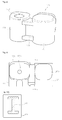
FIG. 1 is a perspective view of a direct injection fuel rail to which a first embodiment of the present invention is applied. -
FIG. 2 is a perspective view of a mounting structure illustrated inFIG. 1 before it is bonded to the fuel rail. -
FIG. 3 is a side view of the mounting structure illustrated inFIG. 2 toward the fuel rail. -
FIG. 4 is a cross-sectional view cut along a line A-A illustrated inFIG. 3 . -
FIG. 5 is a perspective view of a direct injection fuel rail to which a second embodiment of the present invention is applied. -
FIG. 6 is a perspective view of a mounting structure illustrated inFIG. 5 before it is bonded to the fuel rail. -
FIG. 7 is a side view of the mounting structure illustrated inFIG. 6 toward the fuel rail. -
FIG. 8 is a perspective view of a mounting structure according to a third embodiment of the present invention, before it is bonded to a fuel rail. -
FIG. 9 is a side view of the mounting structure illustrated inFIG. 8 toward the fuel rail. -
FIG. 10 is a cross-sectional view cut along a line B-B illustrated inFIG. 9 . -
FIGS. 11A through 11C are diagrams for comparing stresses between embodiments of the present invention and a comparative example. -
FIGS. 12A through 12C are diagrams showing stress distributions corresponding toFIGS. 11A through 11C . - Hereinafter, the present invention will be described in detail by explaining embodiments of the invention with reference to the attached drawings.
-
FIG. 1 is a perspective view of a direct injection fuel rail to which a first embodiment of the present invention is applied.FIG. 2 is a perspective view of a mounting structure illustrated inFIG. 1 before it is bonded to the fuel rail.FIG. 3 is a side view of the mounting structure illustrated inFIG. 2 toward the fuel rail.FIG. 4 is a cross-sectional view of a bridge cut along a line A-A illustrated inFIG. 3 . - As illustrated in
FIGS. 1 through 4 , thefuel rail 100 to which the first embodiment is applied has a configuration in which a plurality ofmounting structures 120 each including aninjector cup 122 are bonded to amain pipe 110 by using a welding (brazing) method. Here, the brazing method refers to a bonding method using a filler metal such as a non-ferrous metal or its alloy having a melting point lower than that of a base metal and for melting only the filler metal without melting the base metal. - The
mounting structure 120 comprises theinjector cup 122 and amount unit 124 connected to thefuel rail 100, and may be integrally processed or casted as one component or may be formed by welding (brazing) theinjector cup 122 and themount unit 124 to each other via thebridge 126. - The
injector cup 122 is a part communicating with themain pipe 110 and for injecting a fuel, and includes abonding surface 122a closely coupled to an outer circumferential surface of themain pipe 110, and ahole 122b communicating with themain pipe 110. - The
mount unit 124 is a mounting boss combined with a fixing member (not shown). Since themain pipe 110 is brazed to an outer surface of the mounting boss, abonding surface 123 is formed on the outer surface of themount unit 124 contacting themain pipe 110, and ahole 124b into which the fixing member is inserted is formed along a length direction of the mounting boss. - Also, the
injector cup 122 has thebonding surface 122a brazed to themain pipe 110, and is connected to and integrated with themounting structure 123 via thebridge 126. - In this case, as illustrated in
FIG. 4 , thebridge 126 may have a rectangular cross section vertically extending along an axis of themount unit 124 or theinjector cup 122 in order to relatively increase a resistance strength per unit cross-sectional area against a bending force from theinjector cup 122 due to a repulsive force when a fuel is injected. -
FIG. 5 is a perspective view of a direct injection fuel rail to which a second embodiment of the present invention is applied.FIG. 6 is a perspective view of a mounting structure illustrated inFIG. 5 before it is bonded to the fuel rail.FIG. 7 is a side view of the mounting structure illustrated inFIG. 6 toward the fuel rail. - As illustrated in
FIGS. 5 through 7 , as in the first embodiment, thefuel rail 100 to which the second embodiment is applied has a configuration in which a plurality ofmounting structures 120 each including aninjector cup 122 are bonded to amain pipe 110 by using a welding (brazing) method. Theinjector cup 122 is the same as that of the first embodiment and thus is not described in detail here. - However, a
mount unit 124 is a mounting boss combined with a fixing member (not shown) and has arecessed surface 124a formed in an outer surface of themount unit 124 so as not to contact an outer surface of themain pipe 110. Accordingly, themount unit 124 is separated from themain pipe 110 by a predetermined distance and is connected to and integrated with themain pipe 110 via abridge 126. -
FIG. 8 is a perspective view of a mounting structure according to a third embodiment of the present invention, before it is bonded to a fuel rail.FIG. 9 is a side view of the mounting structure illustrated inFIG. 8 toward the fuel rail.FIG. 10 is a cross-sectional view cut along a line B-B illustrated inFIG. 9 . - As illustrated in
FIGS. 8 through 10 , themounting structure 120 according to the third embodiment is the same as that of the second embodiment except that abridge 126 for connecting amount unit 124 and aninjector cup 122 has an I-shaped cross section vertically extending along an axis of themount unit 124 or theinjector cup 122, and thus other elements having like reference numerals are not described in detail here. - However, due to the I-shaped cross section, the
mounting structure 120 of the third embodiment may have a maximum flexural strength per unit cross-sectional area against a bending force from theinjector cup 122. - The above-described
mounting structure 120 according to the present invention may prevent concentration of stress on a brazed part for fixing themount unit 124 and theinjector cup 122, may prevent deformation of thebridge 126 for connecting theinjector cup 122 displaced due to the pressure of a fuel in thefuel rail 100 and themount unit 124 connected to a fixing part of an engine head, may allow themount unit 124 and theinjector cup 122 to be integrally processed or casted, and may theinjector cup 122 and themount unit 124, or only the non-brazed (non-welded)mount unit 124 to absorb displacement generated due to pressure and heat by brazing (welding) theinjector cup 122 to themain pipe 110 and brazing (welding) or separating themount unit 124 to or from themain pipe 110, thereby ensuring resistance against fatigue fracture and improving manufacturability. -
FIGS. 11A through 11C, and 12A through 12C are diagrams showing stresses in a finite element method (FEM) by comparing brazed (welded) parts between embodiments of the present invention and a comparative example. -
FIGS. 11A and 12A show the comparative example when an injector cup and a mount unit are separately brazed (welded) to a main pipe. A stress on a bonding part between the injector cup and the main pipe is 357.2MPa, and a stress on a bonding part between the mount unit and the main pipe is 267.6MPa. -
FIGS. 11B and 12B show the first embodiment of the present invention when an injector cup and a mount unit are connected to each other via a bridge, and the injector cup and the mount unit are separately brazed (welded) to a main pipe. A stress on a bonding part between the injector cup and the main pipe is 167.5MPa, and a stress on a bonding part between the mount unit and the main pipe is 211.5MPa. -
FIGS. 11C and 12C show the second embodiment of the present invention when an injector cup and a mount unit are connected to each other via a bridge, the injector cup is brazed (welded) to a main pipe, and the mount unit is separated form the main pipe. Only a stress on a bonding part between the injector cup and the main pipe is 176MPa. - As illustrated in
FIGS. 11A through 11C, and 12A through 12C , the second embodiment illustrated inFIGS. 11C and 12C may be the most appropriate case in terms of stress and may easily ensure precise assembling positions of the mount unit and the injector cup because a mounting structure is fixed onto the main pipe with reference to the injector cup. Also, the mounting structure of the second embodiment may easily align assembling positions because it is bonded to the main pipe at one position, i.e., the injector cup. - Meanwhile, in the first embodiment illustrated in
FIGS. 11B and 12B , although the stress on a bonding part between the injector cup and the main pipe is 167.5MPa, since a stress of 211.5MPa occurs on a bonding part between the mount unit and the main pipe and both the injector cup and the mount unit are bonded to the main pipe, precise assembling positions may not be easily ensured. - In a mounting structure for a direct injection fuel rail, according to the present invention, a manufacturing method may be easily selected according to a situation after the mounting structure is processed or casted according to the configuration of the fuel rail, and may easily ensure precise assembling positions of a mount unit and an injector cup because the mounting structure is fixed onto a main pipe with reference to the injector cup. Also, since only the injector cup is brazed, displacement generated due to pressure and heat may be dispersed, concentration of stress may be reduced, and thus resistance against fatigue fracture may be ensured.
Claims (6)
- A mounting structure for a direct injection fuel rail, the mounting structure comprising:a mount unit for supporting a main pipe; andan injector cup combined with the main pipe,wherein the injector cup is bonded to the main pipe and is connected to and integrated with the mount unit via a bridge.
- The mounting structure of claim 1, wherein the mount unit is bonded to the main pipe.
- The mounting structure of claim 1, wherein the mount unit is separated from the main pipe.
- The mounting structure of claim 3, wherein the mount unit is a mounting boss combined with a fixing member, and has a recessed surface formed in an outer surface of the mount unit so as not to contact an outer surface of the main pipe.
- The mounting structure of any one of claims 1 to 4, wherein the bridge has a rectangular cross section vertically extending along an axis of the mount unit or the injector cup.
- The mounting structure of any one of claims 1 to 4, wherein the bridge has an I -shaped cross section vertically extending along an axis of the mount unit or the injector cup.
Applications Claiming Priority (2)
| Application Number | Priority Date | Filing Date | Title |
|---|---|---|---|
| KR1020090073688A KR101027791B1 (en) | 2009-08-11 | 2009-08-11 | structure for mounting for GDI fuel-rail |
| PCT/KR2010/005005 WO2011019150A2 (en) | 2009-08-11 | 2010-07-29 | Mounting structure for a direct injection fuel rail |
Publications (3)
| Publication Number | Publication Date |
|---|---|
| EP2466111A2 true EP2466111A2 (en) | 2012-06-20 |
| EP2466111A4 EP2466111A4 (en) | 2013-05-22 |
| EP2466111B1 EP2466111B1 (en) | 2014-11-12 |
Family
ID=43586607
Family Applications (1)
| Application Number | Title | Priority Date | Filing Date |
|---|---|---|---|
| EP10808299.1A Active EP2466111B1 (en) | 2009-08-11 | 2010-07-29 | Mounting structure for a direct injection fuel rail |
Country Status (4)
| Country | Link |
|---|---|
| US (1) | US8944031B2 (en) |
| EP (1) | EP2466111B1 (en) |
| KR (1) | KR101027791B1 (en) |
| WO (1) | WO2011019150A2 (en) |
Cited By (5)
| Publication number | Priority date | Publication date | Assignee | Title |
|---|---|---|---|---|
| EP3244056A1 (en) * | 2016-05-13 | 2017-11-15 | Continental Automotive GmbH | A fuel rail assembly for an internal combustion engine |
| EP3312408A1 (en) * | 2016-10-19 | 2018-04-25 | Dongbo Ind. Co., Ltd. | Structure of gdi fuel delivery pipe |
| EP3470663A1 (en) | 2017-10-12 | 2019-04-17 | Continental Automotive GmbH | A fuel rail assembly for a fuel injection system for an internal combustion engine |
| CN109653920A (en) * | 2017-10-12 | 2019-04-19 | 大陆汽车有限公司 | Brazed products, fuel rail assembly and the method for producing brazed products, fuel rail assembly |
| EP3667058A1 (en) * | 2018-12-13 | 2020-06-17 | Vitesco Technologies GmbH | Fuel rail, fixing bracket, method for manufacturing a fuel rail and method for manufacturing a fixing bracket |
Families Citing this family (21)
| Publication number | Priority date | Publication date | Assignee | Title |
|---|---|---|---|---|
| JP5510992B2 (en) * | 2008-06-30 | 2014-06-04 | 臼井国際産業株式会社 | Fuel rail for high pressure direct injection internal combustion engine and method for manufacturing the same |
| JP5912410B2 (en) * | 2011-10-26 | 2016-04-27 | トヨタ自動車株式会社 | Fuel delivery pipe fastening structure |
| KR101160446B1 (en) * | 2012-04-18 | 2012-06-28 | 일진제강(주) | Injector cup unit for connecting fuel injection pipe and manufacturing method thereof |
| US9422903B2 (en) | 2013-05-01 | 2016-08-23 | Denso International America, Inc. | Connecting element for GDI tube stress reduction |
| KR101509727B1 (en) * | 2013-10-02 | 2015-04-07 | 주식회사 시스트란인터내셔널 | Apparatus for creating alignment corpus based on unsupervised alignment and method thereof, and apparatus for performing morphological analysis of non-canonical text using the alignment corpus and method thereof |
| JP6230407B2 (en) * | 2013-12-19 | 2017-11-15 | マルヤス工業株式会社 | High pressure fuel delivery pipe assembly for direct injection engines |
| KR101633367B1 (en) * | 2014-12-10 | 2016-07-08 | 주식회사 현대케피코 | Fixing Structures of Gasoline Direct Injector |
| KR101715037B1 (en) * | 2015-04-08 | 2017-04-03 | 주식회사 세림티앤디 | Manufacturing method nd euipment using cold forging of fuel rail boss for vehicle engine |
| CN104863770A (en) * | 2015-05-28 | 2015-08-26 | 上海臼井发动机零部件有限公司 | High-pressure fuel distribution pipe for direct injection gasoline engine |
| JP6521785B2 (en) * | 2015-08-04 | 2019-05-29 | 株式会社オティックス | Fuel delivery pipe |
| DE102015120962B4 (en) * | 2015-12-02 | 2020-09-24 | Benteler Automobiltechnik Gmbh | Fuel rail and method of making a fuel rail |
| EP3199794B1 (en) * | 2016-02-01 | 2018-06-27 | TI Automotive (Heidelberg) GmbH | Fuel distribution rail and method for producing the same |
| DE102016204025B4 (en) * | 2016-03-11 | 2021-05-27 | Hirschvogel Umformtechnik Gmbh | Internal pressure loaded component (rail) as well as process for its production |
| EP3232046A1 (en) | 2016-04-12 | 2017-10-18 | Continental Automotive GmbH | Fuel rail and fuel rail assembly |
| KR101861002B1 (en) * | 2016-07-08 | 2018-05-24 | 주식회사 현대케피코 | Fuel rail assembly for vehicle |
| DE102016212936A1 (en) * | 2016-07-15 | 2018-01-18 | Robert Bosch Gmbh | Fuel injection system and arrangement for a fuel injection system |
| KR101777062B1 (en) * | 2016-10-21 | 2017-09-08 | 주식회사 현대케피코 | Mounting structure of fuel rail |
| TR201914989A2 (en) * | 2019-10-02 | 2021-04-21 | Bosch Gmbh Robert | Component for an injection system, particularly a fuel rail, injection system, and method for manufacturing such a component. |
| EP3812574A1 (en) | 2019-10-25 | 2021-04-28 | Vitesco Technologies GmbH | Fuel rail assembly for an internal combustion engine |
| KR102312717B1 (en) | 2020-04-27 | 2021-10-14 | (주)모토닉 | Fuel rail connection structure for LPDI automobile |
| KR102431857B1 (en) | 2020-11-19 | 2022-08-11 | 정보테크(주) | Injector housing fixed method of the vehicle fuel rail |
Citations (4)
| Publication number | Priority date | Publication date | Assignee | Title |
|---|---|---|---|---|
| DE19953942A1 (en) * | 1998-11-12 | 2000-07-20 | Avl List Gmbh | Fuel feed for injection IC engine has separate connector modules threaded onto a fuel pipe and linking to the separate injectors |
| GB2416373A (en) * | 2004-07-22 | 2006-01-25 | Benteler Automobiltechnik Gmbh | Fuel feed for an internal combustion engine with direct injection |
| DE102004037787A1 (en) * | 2004-08-03 | 2006-02-23 | Benteler Automobiltechnik Gmbh | Fuel supply for internal combustion engine, has feed line with branch pipes on one side, and diagonal bores provided in connecting consoles of pipes penetrate centering spigot in longitudinal direction to connect blind holes with feed line |
| DE102006010244B3 (en) * | 2006-03-02 | 2007-09-06 | Benteler Automobiltechnik Gmbh | Fuel distribution, for an internal combustion motor, has an injection molded plastics shrouding at the junction between the distribution tube and branch connections to the injectors with sleeve sections around them |
Family Cites Families (16)
| Publication number | Priority date | Publication date | Assignee | Title |
|---|---|---|---|---|
| JPH0290359U (en) * | 1988-12-28 | 1990-07-18 | ||
| US5970953A (en) * | 1999-01-12 | 1999-10-26 | Siemens Automotive Corporation | High pressure injector clip |
| US6913210B2 (en) * | 2001-09-28 | 2005-07-05 | Holley Performance Products | Fuel injector nozzle adapter |
| JP3964691B2 (en) | 2002-02-15 | 2007-08-22 | 臼井国際産業株式会社 | Fuel delivery pipe |
| JP2004052093A (en) * | 2002-07-24 | 2004-02-19 | Sanoh Industrial Co Ltd | Multilayer plated automobile fuel piping part |
| EP1510687A2 (en) * | 2003-08-28 | 2005-03-02 | Siemens VDO Automotive Corporation | Intake manifold with injectors and captive fuel rail |
| JP4184238B2 (en) | 2003-11-19 | 2008-11-19 | 臼井国際産業株式会社 | Fuel delivery pipe |
| JP4199709B2 (en) | 2004-08-03 | 2008-12-17 | 臼井国際産業株式会社 | Fuel delivery pipe |
| US7159570B2 (en) * | 2004-12-03 | 2007-01-09 | Millennium Industries Corp. | Fuel injector retention clip |
| US7360524B2 (en) * | 2004-12-03 | 2008-04-22 | Millenium Industries, Inc. | Fuel injector retention clip |
| US20060163243A1 (en) * | 2005-01-25 | 2006-07-27 | Stieler David C | Method of coupling fuel system components |
| JP4456052B2 (en) * | 2005-09-27 | 2010-04-28 | 臼井国際産業株式会社 | Fuel delivery pipe |
| US7699041B2 (en) * | 2007-12-11 | 2010-04-20 | Delphi Technologies, Inc. | Fuel distribution tube for direct injection fuel rail assemblies |
| JP5510992B2 (en) * | 2008-06-30 | 2014-06-04 | 臼井国際産業株式会社 | Fuel rail for high pressure direct injection internal combustion engine and method for manufacturing the same |
| US20100012093A1 (en) * | 2008-07-18 | 2010-01-21 | Pepperine Dean M | High-pressure fuel injector to fuel rail connection |
| US7798127B2 (en) * | 2008-08-05 | 2010-09-21 | Delphi Technologies, Inc. | Top mounting fuel injector clip |
-
2009
- 2009-08-11 KR KR1020090073688A patent/KR101027791B1/en active IP Right Grant
-
2010
- 2010-07-29 US US13/390,078 patent/US8944031B2/en active Active
- 2010-07-29 WO PCT/KR2010/005005 patent/WO2011019150A2/en active Application Filing
- 2010-07-29 EP EP10808299.1A patent/EP2466111B1/en active Active
Patent Citations (4)
| Publication number | Priority date | Publication date | Assignee | Title |
|---|---|---|---|---|
| DE19953942A1 (en) * | 1998-11-12 | 2000-07-20 | Avl List Gmbh | Fuel feed for injection IC engine has separate connector modules threaded onto a fuel pipe and linking to the separate injectors |
| GB2416373A (en) * | 2004-07-22 | 2006-01-25 | Benteler Automobiltechnik Gmbh | Fuel feed for an internal combustion engine with direct injection |
| DE102004037787A1 (en) * | 2004-08-03 | 2006-02-23 | Benteler Automobiltechnik Gmbh | Fuel supply for internal combustion engine, has feed line with branch pipes on one side, and diagonal bores provided in connecting consoles of pipes penetrate centering spigot in longitudinal direction to connect blind holes with feed line |
| DE102006010244B3 (en) * | 2006-03-02 | 2007-09-06 | Benteler Automobiltechnik Gmbh | Fuel distribution, for an internal combustion motor, has an injection molded plastics shrouding at the junction between the distribution tube and branch connections to the injectors with sleeve sections around them |
Non-Patent Citations (1)
| Title |
|---|
| See also references of WO2011019150A2 * |
Cited By (8)
| Publication number | Priority date | Publication date | Assignee | Title |
|---|---|---|---|---|
| EP3244056A1 (en) * | 2016-05-13 | 2017-11-15 | Continental Automotive GmbH | A fuel rail assembly for an internal combustion engine |
| US10436163B2 (en) | 2016-05-13 | 2019-10-08 | Cpt Group Gmbh | Fuel rail assembly for an internal combustion engine |
| EP3312408A1 (en) * | 2016-10-19 | 2018-04-25 | Dongbo Ind. Co., Ltd. | Structure of gdi fuel delivery pipe |
| EP3470663A1 (en) | 2017-10-12 | 2019-04-17 | Continental Automotive GmbH | A fuel rail assembly for a fuel injection system for an internal combustion engine |
| CN109653920A (en) * | 2017-10-12 | 2019-04-19 | 大陆汽车有限公司 | Brazed products, fuel rail assembly and the method for producing brazed products, fuel rail assembly |
| CN109653920B (en) * | 2017-10-12 | 2022-02-08 | 大陆汽车有限公司 | Brazed article, fuel rail assembly and method for producing brazed article, fuel rail assembly |
| EP3667058A1 (en) * | 2018-12-13 | 2020-06-17 | Vitesco Technologies GmbH | Fuel rail, fixing bracket, method for manufacturing a fuel rail and method for manufacturing a fixing bracket |
| WO2020120615A1 (en) * | 2018-12-13 | 2020-06-18 | Vitesco Technologies GmbH | Fuel rail, fixing bracket, method for manufacturing a fuel rail and method for manufacturing a fixing bracket |
Also Published As
| Publication number | Publication date |
|---|---|
| WO2011019150A3 (en) | 2011-05-26 |
| KR101027791B1 (en) | 2011-04-07 |
| KR20110016140A (en) | 2011-02-17 |
| US20120138020A1 (en) | 2012-06-07 |
| EP2466111A4 (en) | 2013-05-22 |
| WO2011019150A2 (en) | 2011-02-17 |
| WO2011019150A9 (en) | 2011-07-07 |
| US8944031B2 (en) | 2015-02-03 |
| EP2466111B1 (en) | 2014-11-12 |
Similar Documents
| Publication | Publication Date | Title |
|---|---|---|
| US8944031B2 (en) | Mounting structure for a direct injection fuel rail | |
| US10132282B2 (en) | Fuel rail assembly | |
| KR100890577B1 (en) | Dual-system fuel injection engine | |
| JP5447138B2 (en) | High-pressure fuel piping structure | |
| JP4629724B2 (en) | Injector mounting structure | |
| EP1892408A1 (en) | Injector, fuel cup and holder | |
| EP2902616B1 (en) | Coupling device | |
| CN104246204B (en) | Arrangement with a fuel distributor and a plurality of fuel injection valves | |
| EP3312408B1 (en) | Structure of gdi fuel delivery pipe | |
| US9422903B2 (en) | Connecting element for GDI tube stress reduction | |
| CN108235715B (en) | Mounting structure for fuel rail | |
| JPWO2016042897A1 (en) | Fuel rail | |
| JP4680829B2 (en) | Fuel delivery pipe | |
| KR20150048548A (en) | Fuel Rail for Vehicle | |
| CN104428526A (en) | High-pressure fuel pump for a fuel system of an internal combustion engine | |
| KR101861002B1 (en) | Fuel rail assembly for vehicle | |
| US7584746B1 (en) | Fuel rail radiated noise reduction | |
| JP6194722B2 (en) | Engine fuel injector | |
| US10947941B2 (en) | Fuel-injection system and assembly therefor | |
| JP3990649B2 (en) | Resin intake manifold | |
| US11781501B2 (en) | Engine head structure | |
| JP2003184694A (en) | Fuel delivery pipe and manufacture thereof | |
| JP2017137774A (en) | Fuel supply system for internal combustion engine | |
| JP2009013885A (en) | Fuel supply device for direct injection type v-engine and direct injection type v-engine | |
| KR20130049609A (en) | Module for connecting fuel rail to a cylinder head |
Legal Events
| Date | Code | Title | Description |
|---|---|---|---|
| PUAI | Public reference made under article 153(3) epc to a published international application that has entered the european phase |
Free format text: ORIGINAL CODE: 0009012 |
|
| 17P | Request for examination filed |
Effective date: 20120206 |
|
| AK | Designated contracting states |
Kind code of ref document: A2 Designated state(s): AL AT BE BG CH CY CZ DE DK EE ES FI FR GB GR HR HU IE IS IT LI LT LU LV MC MK MT NL NO PL PT RO SE SI SK SM TR |
|
| DAX | Request for extension of the european patent (deleted) | ||
| A4 | Supplementary search report drawn up and despatched |
Effective date: 20130418 |
|
| RIC1 | Information provided on ipc code assigned before grant |
Ipc: F02M 55/04 20060101ALI20130412BHEP Ipc: F02M 55/02 20060101AFI20130412BHEP Ipc: F02M 61/14 20060101ALI20130412BHEP |
|
| GRAP | Despatch of communication of intention to grant a patent |
Free format text: ORIGINAL CODE: EPIDOSNIGR1 |
|
| INTG | Intention to grant announced |
Effective date: 20140523 |
|
| GRAS | Grant fee paid |
Free format text: ORIGINAL CODE: EPIDOSNIGR3 |
|
| GRAA | (expected) grant |
Free format text: ORIGINAL CODE: 0009210 |
|
| AK | Designated contracting states |
Kind code of ref document: B1 Designated state(s): AL AT BE BG CH CY CZ DE DK EE ES FI FR GB GR HR HU IE IS IT LI LT LU LV MC MK MT NL NO PL PT RO SE SI SK SM TR |
|
| REG | Reference to a national code |
Ref country code: GB Ref legal event code: FG4D |
|
| REG | Reference to a national code |
Ref country code: CH Ref legal event code: EP |
|
| REG | Reference to a national code |
Ref country code: AT Ref legal event code: REF Ref document number: 695934 Country of ref document: AT Kind code of ref document: T Effective date: 20141115 |
|
| REG | Reference to a national code |
Ref country code: IE Ref legal event code: FG4D |
|
| REG | Reference to a national code |
Ref country code: DE Ref legal event code: R096 Ref document number: 602010020248 Country of ref document: DE Effective date: 20141224 |
|
| REG | Reference to a national code |
Ref country code: NL Ref legal event code: VDEP Effective date: 20141112 |
|
| REG | Reference to a national code |
Ref country code: AT Ref legal event code: MK05 Ref document number: 695934 Country of ref document: AT Kind code of ref document: T Effective date: 20141112 |
|
| PG25 | Lapsed in a contracting state [announced via postgrant information from national office to epo] |
Ref country code: FI Free format text: LAPSE BECAUSE OF FAILURE TO SUBMIT A TRANSLATION OF THE DESCRIPTION OR TO PAY THE FEE WITHIN THE PRESCRIBED TIME-LIMIT Effective date: 20141112 Ref country code: IS Free format text: LAPSE BECAUSE OF FAILURE TO SUBMIT A TRANSLATION OF THE DESCRIPTION OR TO PAY THE FEE WITHIN THE PRESCRIBED TIME-LIMIT Effective date: 20150312 Ref country code: NO Free format text: LAPSE BECAUSE OF FAILURE TO SUBMIT A TRANSLATION OF THE DESCRIPTION OR TO PAY THE FEE WITHIN THE PRESCRIBED TIME-LIMIT Effective date: 20150212 Ref country code: PT Free format text: LAPSE BECAUSE OF FAILURE TO SUBMIT A TRANSLATION OF THE DESCRIPTION OR TO PAY THE FEE WITHIN THE PRESCRIBED TIME-LIMIT Effective date: 20150312 Ref country code: NL Free format text: LAPSE BECAUSE OF FAILURE TO SUBMIT A TRANSLATION OF THE DESCRIPTION OR TO PAY THE FEE WITHIN THE PRESCRIBED TIME-LIMIT Effective date: 20141112 Ref country code: LT Free format text: LAPSE BECAUSE OF FAILURE TO SUBMIT A TRANSLATION OF THE DESCRIPTION OR TO PAY THE FEE WITHIN THE PRESCRIBED TIME-LIMIT Effective date: 20141112 Ref country code: ES Free format text: LAPSE BECAUSE OF FAILURE TO SUBMIT A TRANSLATION OF THE DESCRIPTION OR TO PAY THE FEE WITHIN THE PRESCRIBED TIME-LIMIT Effective date: 20141112 |
|
| PG25 | Lapsed in a contracting state [announced via postgrant information from national office to epo] |
Ref country code: CY Free format text: LAPSE BECAUSE OF FAILURE TO SUBMIT A TRANSLATION OF THE DESCRIPTION OR TO PAY THE FEE WITHIN THE PRESCRIBED TIME-LIMIT Effective date: 20141112 Ref country code: SE Free format text: LAPSE BECAUSE OF FAILURE TO SUBMIT A TRANSLATION OF THE DESCRIPTION OR TO PAY THE FEE WITHIN THE PRESCRIBED TIME-LIMIT Effective date: 20141112 Ref country code: PL Free format text: LAPSE BECAUSE OF FAILURE TO SUBMIT A TRANSLATION OF THE DESCRIPTION OR TO PAY THE FEE WITHIN THE PRESCRIBED TIME-LIMIT Effective date: 20141112 Ref country code: AT Free format text: LAPSE BECAUSE OF FAILURE TO SUBMIT A TRANSLATION OF THE DESCRIPTION OR TO PAY THE FEE WITHIN THE PRESCRIBED TIME-LIMIT Effective date: 20141112 Ref country code: HR Free format text: LAPSE BECAUSE OF FAILURE TO SUBMIT A TRANSLATION OF THE DESCRIPTION OR TO PAY THE FEE WITHIN THE PRESCRIBED TIME-LIMIT Effective date: 20141112 Ref country code: LV Free format text: LAPSE BECAUSE OF FAILURE TO SUBMIT A TRANSLATION OF THE DESCRIPTION OR TO PAY THE FEE WITHIN THE PRESCRIBED TIME-LIMIT Effective date: 20141112 Ref country code: GR Free format text: LAPSE BECAUSE OF FAILURE TO SUBMIT A TRANSLATION OF THE DESCRIPTION OR TO PAY THE FEE WITHIN THE PRESCRIBED TIME-LIMIT Effective date: 20150213 |
|
| PG25 | Lapsed in a contracting state [announced via postgrant information from national office to epo] |
Ref country code: RO Free format text: LAPSE BECAUSE OF FAILURE TO SUBMIT A TRANSLATION OF THE DESCRIPTION OR TO PAY THE FEE WITHIN THE PRESCRIBED TIME-LIMIT Effective date: 20141112 Ref country code: SK Free format text: LAPSE BECAUSE OF FAILURE TO SUBMIT A TRANSLATION OF THE DESCRIPTION OR TO PAY THE FEE WITHIN THE PRESCRIBED TIME-LIMIT Effective date: 20141112 Ref country code: CZ Free format text: LAPSE BECAUSE OF FAILURE TO SUBMIT A TRANSLATION OF THE DESCRIPTION OR TO PAY THE FEE WITHIN THE PRESCRIBED TIME-LIMIT Effective date: 20141112 Ref country code: DK Free format text: LAPSE BECAUSE OF FAILURE TO SUBMIT A TRANSLATION OF THE DESCRIPTION OR TO PAY THE FEE WITHIN THE PRESCRIBED TIME-LIMIT Effective date: 20141112 Ref country code: EE Free format text: LAPSE BECAUSE OF FAILURE TO SUBMIT A TRANSLATION OF THE DESCRIPTION OR TO PAY THE FEE WITHIN THE PRESCRIBED TIME-LIMIT Effective date: 20141112 |
|
| REG | Reference to a national code |
Ref country code: DE Ref legal event code: R097 Ref document number: 602010020248 Country of ref document: DE |
|
| PLBE | No opposition filed within time limit |
Free format text: ORIGINAL CODE: 0009261 |
|
| STAA | Information on the status of an ep patent application or granted ep patent |
Free format text: STATUS: NO OPPOSITION FILED WITHIN TIME LIMIT |
|
| 26N | No opposition filed |
Effective date: 20150813 |
|
| PG25 | Lapsed in a contracting state [announced via postgrant information from national office to epo] |
Ref country code: IT Free format text: LAPSE BECAUSE OF FAILURE TO SUBMIT A TRANSLATION OF THE DESCRIPTION OR TO PAY THE FEE WITHIN THE PRESCRIBED TIME-LIMIT Effective date: 20141112 |
|
| PG25 | Lapsed in a contracting state [announced via postgrant information from national office to epo] |
Ref country code: MC Free format text: LAPSE BECAUSE OF FAILURE TO SUBMIT A TRANSLATION OF THE DESCRIPTION OR TO PAY THE FEE WITHIN THE PRESCRIBED TIME-LIMIT Effective date: 20141112 Ref country code: SI Free format text: LAPSE BECAUSE OF FAILURE TO SUBMIT A TRANSLATION OF THE DESCRIPTION OR TO PAY THE FEE WITHIN THE PRESCRIBED TIME-LIMIT Effective date: 20141112 |
|
| REG | Reference to a national code |
Ref country code: CH Ref legal event code: PL |
|
| GBPC | Gb: european patent ceased through non-payment of renewal fee |
Effective date: 20150729 |
|
| PG25 | Lapsed in a contracting state [announced via postgrant information from national office to epo] |
Ref country code: LU Free format text: LAPSE BECAUSE OF FAILURE TO SUBMIT A TRANSLATION OF THE DESCRIPTION OR TO PAY THE FEE WITHIN THE PRESCRIBED TIME-LIMIT Effective date: 20150729 |
|
| REG | Reference to a national code |
Ref country code: IE Ref legal event code: MM4A |
|
| PG25 | Lapsed in a contracting state [announced via postgrant information from national office to epo] |
Ref country code: GB Free format text: LAPSE BECAUSE OF NON-PAYMENT OF DUE FEES Effective date: 20150729 Ref country code: LI Free format text: LAPSE BECAUSE OF NON-PAYMENT OF DUE FEES Effective date: 20150731 Ref country code: CH Free format text: LAPSE BECAUSE OF NON-PAYMENT OF DUE FEES Effective date: 20150731 |
|
| REG | Reference to a national code |
Ref country code: FR Ref legal event code: ST Effective date: 20160331 |
|
| PG25 | Lapsed in a contracting state [announced via postgrant information from national office to epo] |
Ref country code: FR Free format text: LAPSE BECAUSE OF NON-PAYMENT OF DUE FEES Effective date: 20150731 |
|
| PG25 | Lapsed in a contracting state [announced via postgrant information from national office to epo] |
Ref country code: IE Free format text: LAPSE BECAUSE OF NON-PAYMENT OF DUE FEES Effective date: 20150729 |
|
| PG25 | Lapsed in a contracting state [announced via postgrant information from national office to epo] |
Ref country code: MT Free format text: LAPSE BECAUSE OF FAILURE TO SUBMIT A TRANSLATION OF THE DESCRIPTION OR TO PAY THE FEE WITHIN THE PRESCRIBED TIME-LIMIT Effective date: 20141112 |
|
| PG25 | Lapsed in a contracting state [announced via postgrant information from national office to epo] |
Ref country code: HU Free format text: LAPSE BECAUSE OF FAILURE TO SUBMIT A TRANSLATION OF THE DESCRIPTION OR TO PAY THE FEE WITHIN THE PRESCRIBED TIME-LIMIT; INVALID AB INITIO Effective date: 20100729 Ref country code: SM Free format text: LAPSE BECAUSE OF FAILURE TO SUBMIT A TRANSLATION OF THE DESCRIPTION OR TO PAY THE FEE WITHIN THE PRESCRIBED TIME-LIMIT Effective date: 20141112 Ref country code: BG Free format text: LAPSE BECAUSE OF FAILURE TO SUBMIT A TRANSLATION OF THE DESCRIPTION OR TO PAY THE FEE WITHIN THE PRESCRIBED TIME-LIMIT Effective date: 20141112 |
|
| PG25 | Lapsed in a contracting state [announced via postgrant information from national office to epo] |
Ref country code: TR Free format text: LAPSE BECAUSE OF FAILURE TO SUBMIT A TRANSLATION OF THE DESCRIPTION OR TO PAY THE FEE WITHIN THE PRESCRIBED TIME-LIMIT Effective date: 20141112 |
|
| PG25 | Lapsed in a contracting state [announced via postgrant information from national office to epo] |
Ref country code: BE Free format text: LAPSE BECAUSE OF FAILURE TO SUBMIT A TRANSLATION OF THE DESCRIPTION OR TO PAY THE FEE WITHIN THE PRESCRIBED TIME-LIMIT Effective date: 20141112 |
|
| PG25 | Lapsed in a contracting state [announced via postgrant information from national office to epo] |
Ref country code: MK Free format text: LAPSE BECAUSE OF FAILURE TO SUBMIT A TRANSLATION OF THE DESCRIPTION OR TO PAY THE FEE WITHIN THE PRESCRIBED TIME-LIMIT Effective date: 20141112 |
|
| PG25 | Lapsed in a contracting state [announced via postgrant information from national office to epo] |
Ref country code: AL Free format text: LAPSE BECAUSE OF FAILURE TO SUBMIT A TRANSLATION OF THE DESCRIPTION OR TO PAY THE FEE WITHIN THE PRESCRIBED TIME-LIMIT Effective date: 20141112 |
|
| PGFP | Annual fee paid to national office [announced via postgrant information from national office to epo] |
Ref country code: DE Payment date: 20230620 Year of fee payment: 14 |
|
| REG | Reference to a national code |
Ref country code: DE Ref legal event code: R082 Ref document number: 602010020248 Country of ref document: DE Representative=s name: SCHOPPE, ZIMMERMANN, STOECKELER, ZINKLER, SCHE, DE |