US20060163243A1 - Method of coupling fuel system components - Google Patents
Method of coupling fuel system components Download PDFInfo
- Publication number
- US20060163243A1 US20060163243A1 US11/042,014 US4201405A US2006163243A1 US 20060163243 A1 US20060163243 A1 US 20060163243A1 US 4201405 A US4201405 A US 4201405A US 2006163243 A1 US2006163243 A1 US 2006163243A1
- Authority
- US
- United States
- Prior art keywords
- component
- fuel
- components
- layer
- outer layer
- Prior art date
- Legal status (The legal status is an assumption and is not a legal conclusion. Google has not performed a legal analysis and makes no representation as to the accuracy of the status listed.)
- Abandoned
Links
- 239000000446 fuel Substances 0.000 title claims abstract description 72
- 238000000034 method Methods 0.000 title claims abstract description 41
- 230000008878 coupling Effects 0.000 title claims abstract description 8
- 238000010168 coupling process Methods 0.000 title claims abstract description 8
- 238000005859 coupling reaction Methods 0.000 title claims abstract description 8
- 239000010410 layer Substances 0.000 claims abstract description 44
- 239000012530 fluid Substances 0.000 claims abstract description 27
- 229910052782 aluminium Inorganic materials 0.000 claims abstract description 17
- XAGFODPZIPBFFR-UHFFFAOYSA-N aluminium Chemical compound [Al] XAGFODPZIPBFFR-UHFFFAOYSA-N 0.000 claims abstract description 17
- 239000004677 Nylon Substances 0.000 claims abstract description 10
- 229920001778 nylon Polymers 0.000 claims abstract description 10
- 239000013047 polymeric layer Substances 0.000 claims abstract description 5
- 238000012546 transfer Methods 0.000 claims abstract description 4
- 239000000945 filler Substances 0.000 claims description 12
- 229910000831 Steel Inorganic materials 0.000 claims description 4
- 239000004020 conductor Substances 0.000 claims description 4
- 239000010959 steel Substances 0.000 claims description 4
- 230000006698 induction Effects 0.000 abstract description 4
- 238000003466 welding Methods 0.000 abstract description 3
- 239000002828 fuel tank Substances 0.000 description 13
- 238000005219 brazing Methods 0.000 description 12
- 239000004033 plastic Substances 0.000 description 9
- 229920003023 plastic Polymers 0.000 description 9
- 230000008569 process Effects 0.000 description 6
- 238000004519 manufacturing process Methods 0.000 description 4
- 229910052751 metal Inorganic materials 0.000 description 4
- 239000002184 metal Substances 0.000 description 4
- 238000007792 addition Methods 0.000 description 3
- 229910045601 alloy Inorganic materials 0.000 description 3
- 239000000956 alloy Substances 0.000 description 3
- 230000015572 biosynthetic process Effects 0.000 description 3
- 239000011248 coating agent Substances 0.000 description 3
- 238000000576 coating method Methods 0.000 description 3
- 238000002485 combustion reaction Methods 0.000 description 3
- 238000001816 cooling Methods 0.000 description 3
- ZZUFCTLCJUWOSV-UHFFFAOYSA-N furosemide Chemical compound C1=C(Cl)C(S(=O)(=O)N)=CC(C(O)=O)=C1NCC1=CC=CO1 ZZUFCTLCJUWOSV-UHFFFAOYSA-N 0.000 description 3
- 239000000463 material Substances 0.000 description 3
- 229910001092 metal group alloy Inorganic materials 0.000 description 3
- 238000007747 plating Methods 0.000 description 3
- 230000004907 flux Effects 0.000 description 2
- 150000002739 metals Chemical class 0.000 description 2
- 239000000203 mixture Substances 0.000 description 2
- 238000010422 painting Methods 0.000 description 2
- 229920000642 polymer Polymers 0.000 description 2
- 238000012545 processing Methods 0.000 description 2
- 238000012360 testing method Methods 0.000 description 2
- 229910000838 Al alloy Inorganic materials 0.000 description 1
- OKTJSMMVPCPJKN-UHFFFAOYSA-N Carbon Chemical compound [C] OKTJSMMVPCPJKN-UHFFFAOYSA-N 0.000 description 1
- JHWNWJKBPDFINM-UHFFFAOYSA-N Laurolactam Chemical compound O=C1CCCCCCCCCCCN1 JHWNWJKBPDFINM-UHFFFAOYSA-N 0.000 description 1
- FYYHWMGAXLPEAU-UHFFFAOYSA-N Magnesium Chemical compound [Mg] FYYHWMGAXLPEAU-UHFFFAOYSA-N 0.000 description 1
- 229920000299 Nylon 12 Polymers 0.000 description 1
- 239000004952 Polyamide Substances 0.000 description 1
- 239000002253 acid Substances 0.000 description 1
- 230000009471 action Effects 0.000 description 1
- 238000004378 air conditioning Methods 0.000 description 1
- 125000003368 amide group Chemical group 0.000 description 1
- 238000005452 bending Methods 0.000 description 1
- 229910052799 carbon Inorganic materials 0.000 description 1
- 239000006229 carbon black Substances 0.000 description 1
- 239000003518 caustics Substances 0.000 description 1
- 238000003486 chemical etching Methods 0.000 description 1
- 238000004891 communication Methods 0.000 description 1
- 230000003750 conditioning effect Effects 0.000 description 1
- 230000007797 corrosion Effects 0.000 description 1
- 238000005260 corrosion Methods 0.000 description 1
- 230000007812 deficiency Effects 0.000 description 1
- 238000013461 design Methods 0.000 description 1
- 230000005672 electromagnetic field Effects 0.000 description 1
- 150000004673 fluoride salts Chemical class 0.000 description 1
- 238000010438 heat treatment Methods 0.000 description 1
- 230000001939 inductive effect Effects 0.000 description 1
- 238000001746 injection moulding Methods 0.000 description 1
- 238000003754 machining Methods 0.000 description 1
- 229910052749 magnesium Inorganic materials 0.000 description 1
- 239000011777 magnesium Substances 0.000 description 1
- 230000013011 mating Effects 0.000 description 1
- 238000002844 melting Methods 0.000 description 1
- 230000008018 melting Effects 0.000 description 1
- 238000012986 modification Methods 0.000 description 1
- 230000004048 modification Effects 0.000 description 1
- 238000004806 packaging method and process Methods 0.000 description 1
- 230000035515 penetration Effects 0.000 description 1
- 239000006223 plastic coating Substances 0.000 description 1
- 239000002574 poison Substances 0.000 description 1
- 231100000614 poison Toxicity 0.000 description 1
- 229920002647 polyamide Polymers 0.000 description 1
- 230000000135 prohibitive effect Effects 0.000 description 1
- 230000001681 protective effect Effects 0.000 description 1
- 238000007788 roughening Methods 0.000 description 1
- 239000000243 solution Substances 0.000 description 1
- 238000003860 storage Methods 0.000 description 1
- 238000005728 strengthening Methods 0.000 description 1
- 229920001169 thermoplastic Polymers 0.000 description 1
- 239000004416 thermosoftening plastic Substances 0.000 description 1
- 238000011282 treatment Methods 0.000 description 1
Images

Classifications
-
- B—PERFORMING OPERATIONS; TRANSPORTING
- B29—WORKING OF PLASTICS; WORKING OF SUBSTANCES IN A PLASTIC STATE IN GENERAL
- B29C—SHAPING OR JOINING OF PLASTICS; SHAPING OF MATERIAL IN A PLASTIC STATE, NOT OTHERWISE PROVIDED FOR; AFTER-TREATMENT OF THE SHAPED PRODUCTS, e.g. REPAIRING
- B29C66/00—General aspects of processes or apparatus for joining preformed parts
- B29C66/50—General aspects of joining tubular articles; General aspects of joining long products, i.e. bars or profiled elements; General aspects of joining single elements to tubular articles, hollow articles or bars; General aspects of joining several hollow-preforms to form hollow or tubular articles
- B29C66/51—Joining tubular articles, profiled elements or bars; Joining single elements to tubular articles, hollow articles or bars; Joining several hollow-preforms to form hollow or tubular articles
- B29C66/53—Joining single elements to tubular articles, hollow articles or bars
- B29C66/534—Joining single elements to open ends of tubular or hollow articles or to the ends of bars
-
- B—PERFORMING OPERATIONS; TRANSPORTING
- B29—WORKING OF PLASTICS; WORKING OF SUBSTANCES IN A PLASTIC STATE IN GENERAL
- B29C—SHAPING OR JOINING OF PLASTICS; SHAPING OF MATERIAL IN A PLASTIC STATE, NOT OTHERWISE PROVIDED FOR; AFTER-TREATMENT OF THE SHAPED PRODUCTS, e.g. REPAIRING
- B29C65/00—Joining or sealing of preformed parts, e.g. welding of plastics materials; Apparatus therefor
- B29C65/02—Joining or sealing of preformed parts, e.g. welding of plastics materials; Apparatus therefor by heating, with or without pressure
- B29C65/34—Joining or sealing of preformed parts, e.g. welding of plastics materials; Apparatus therefor by heating, with or without pressure using heated elements which remain in the joint, e.g. "verlorenes Schweisselement"
- B29C65/36—Joining or sealing of preformed parts, e.g. welding of plastics materials; Apparatus therefor by heating, with or without pressure using heated elements which remain in the joint, e.g. "verlorenes Schweisselement" heated by induction
- B29C65/3604—Joining or sealing of preformed parts, e.g. welding of plastics materials; Apparatus therefor by heating, with or without pressure using heated elements which remain in the joint, e.g. "verlorenes Schweisselement" heated by induction characterised by the type of elements heated by induction which remain in the joint
- B29C65/3656—Joining or sealing of preformed parts, e.g. welding of plastics materials; Apparatus therefor by heating, with or without pressure using heated elements which remain in the joint, e.g. "verlorenes Schweisselement" heated by induction characterised by the type of elements heated by induction which remain in the joint being a layer of a multilayer part to be joined, e.g. for joining plastic-metal laminates
-
- B—PERFORMING OPERATIONS; TRANSPORTING
- B29—WORKING OF PLASTICS; WORKING OF SUBSTANCES IN A PLASTIC STATE IN GENERAL
- B29C—SHAPING OR JOINING OF PLASTICS; SHAPING OF MATERIAL IN A PLASTIC STATE, NOT OTHERWISE PROVIDED FOR; AFTER-TREATMENT OF THE SHAPED PRODUCTS, e.g. REPAIRING
- B29C65/00—Joining or sealing of preformed parts, e.g. welding of plastics materials; Apparatus therefor
- B29C65/02—Joining or sealing of preformed parts, e.g. welding of plastics materials; Apparatus therefor by heating, with or without pressure
- B29C65/34—Joining or sealing of preformed parts, e.g. welding of plastics materials; Apparatus therefor by heating, with or without pressure using heated elements which remain in the joint, e.g. "verlorenes Schweisselement"
- B29C65/36—Joining or sealing of preformed parts, e.g. welding of plastics materials; Apparatus therefor by heating, with or without pressure using heated elements which remain in the joint, e.g. "verlorenes Schweisselement" heated by induction
- B29C65/3672—Joining or sealing of preformed parts, e.g. welding of plastics materials; Apparatus therefor by heating, with or without pressure using heated elements which remain in the joint, e.g. "verlorenes Schweisselement" heated by induction characterised by the composition of the elements heated by induction which remain in the joint
- B29C65/3676—Joining or sealing of preformed parts, e.g. welding of plastics materials; Apparatus therefor by heating, with or without pressure using heated elements which remain in the joint, e.g. "verlorenes Schweisselement" heated by induction characterised by the composition of the elements heated by induction which remain in the joint being metallic
- B29C65/368—Joining or sealing of preformed parts, e.g. welding of plastics materials; Apparatus therefor by heating, with or without pressure using heated elements which remain in the joint, e.g. "verlorenes Schweisselement" heated by induction characterised by the composition of the elements heated by induction which remain in the joint being metallic with a polymer coating
-
- B—PERFORMING OPERATIONS; TRANSPORTING
- B29—WORKING OF PLASTICS; WORKING OF SUBSTANCES IN A PLASTIC STATE IN GENERAL
- B29C—SHAPING OR JOINING OF PLASTICS; SHAPING OF MATERIAL IN A PLASTIC STATE, NOT OTHERWISE PROVIDED FOR; AFTER-TREATMENT OF THE SHAPED PRODUCTS, e.g. REPAIRING
- B29C66/00—General aspects of processes or apparatus for joining preformed parts
- B29C66/01—General aspects dealing with the joint area or with the area to be joined
- B29C66/05—Particular design of joint configurations
- B29C66/10—Particular design of joint configurations particular design of the joint cross-sections
- B29C66/11—Joint cross-sections comprising a single joint-segment, i.e. one of the parts to be joined comprising a single joint-segment in the joint cross-section
- B29C66/112—Single lapped joints
- B29C66/1122—Single lap to lap joints, i.e. overlap joints
-
- B—PERFORMING OPERATIONS; TRANSPORTING
- B29—WORKING OF PLASTICS; WORKING OF SUBSTANCES IN A PLASTIC STATE IN GENERAL
- B29C—SHAPING OR JOINING OF PLASTICS; SHAPING OF MATERIAL IN A PLASTIC STATE, NOT OTHERWISE PROVIDED FOR; AFTER-TREATMENT OF THE SHAPED PRODUCTS, e.g. REPAIRING
- B29C66/00—General aspects of processes or apparatus for joining preformed parts
- B29C66/01—General aspects dealing with the joint area or with the area to be joined
- B29C66/05—Particular design of joint configurations
- B29C66/10—Particular design of joint configurations particular design of the joint cross-sections
- B29C66/12—Joint cross-sections combining only two joint-segments; Tongue and groove joints; Tenon and mortise joints; Stepped joint cross-sections
- B29C66/124—Tongue and groove joints
- B29C66/1244—Tongue and groove joints characterised by the male part, i.e. the part comprising the tongue
- B29C66/12441—Tongue and groove joints characterised by the male part, i.e. the part comprising the tongue being a single wall
-
- B—PERFORMING OPERATIONS; TRANSPORTING
- B29—WORKING OF PLASTICS; WORKING OF SUBSTANCES IN A PLASTIC STATE IN GENERAL
- B29C—SHAPING OR JOINING OF PLASTICS; SHAPING OF MATERIAL IN A PLASTIC STATE, NOT OTHERWISE PROVIDED FOR; AFTER-TREATMENT OF THE SHAPED PRODUCTS, e.g. REPAIRING
- B29C66/00—General aspects of processes or apparatus for joining preformed parts
- B29C66/01—General aspects dealing with the joint area or with the area to be joined
- B29C66/05—Particular design of joint configurations
- B29C66/10—Particular design of joint configurations particular design of the joint cross-sections
- B29C66/12—Joint cross-sections combining only two joint-segments; Tongue and groove joints; Tenon and mortise joints; Stepped joint cross-sections
- B29C66/124—Tongue and groove joints
- B29C66/1246—Tongue and groove joints characterised by the female part, i.e. the part comprising the groove
- B29C66/12469—Tongue and groove joints characterised by the female part, i.e. the part comprising the groove being asymmetric
-
- B—PERFORMING OPERATIONS; TRANSPORTING
- B29—WORKING OF PLASTICS; WORKING OF SUBSTANCES IN A PLASTIC STATE IN GENERAL
- B29C—SHAPING OR JOINING OF PLASTICS; SHAPING OF MATERIAL IN A PLASTIC STATE, NOT OTHERWISE PROVIDED FOR; AFTER-TREATMENT OF THE SHAPED PRODUCTS, e.g. REPAIRING
- B29C66/00—General aspects of processes or apparatus for joining preformed parts
- B29C66/50—General aspects of joining tubular articles; General aspects of joining long products, i.e. bars or profiled elements; General aspects of joining single elements to tubular articles, hollow articles or bars; General aspects of joining several hollow-preforms to form hollow or tubular articles
- B29C66/51—Joining tubular articles, profiled elements or bars; Joining single elements to tubular articles, hollow articles or bars; Joining several hollow-preforms to form hollow or tubular articles
- B29C66/53—Joining single elements to tubular articles, hollow articles or bars
- B29C66/532—Joining single elements to the wall of tubular articles, hollow articles or bars
- B29C66/5324—Joining single elements to the wall of tubular articles, hollow articles or bars said single elements being substantially annular, i.e. of finite length
- B29C66/53245—Joining single elements to the wall of tubular articles, hollow articles or bars said single elements being substantially annular, i.e. of finite length said articles being hollow
-
- B—PERFORMING OPERATIONS; TRANSPORTING
- B29—WORKING OF PLASTICS; WORKING OF SUBSTANCES IN A PLASTIC STATE IN GENERAL
- B29C—SHAPING OR JOINING OF PLASTICS; SHAPING OF MATERIAL IN A PLASTIC STATE, NOT OTHERWISE PROVIDED FOR; AFTER-TREATMENT OF THE SHAPED PRODUCTS, e.g. REPAIRING
- B29C66/00—General aspects of processes or apparatus for joining preformed parts
- B29C66/70—General aspects of processes or apparatus for joining preformed parts characterised by the composition, physical properties or the structure of the material of the parts to be joined; Joining with non-plastics material
- B29C66/72—General aspects of processes or apparatus for joining preformed parts characterised by the composition, physical properties or the structure of the material of the parts to be joined; Joining with non-plastics material characterised by the structure of the material of the parts to be joined
- B29C66/723—General aspects of processes or apparatus for joining preformed parts characterised by the composition, physical properties or the structure of the material of the parts to be joined; Joining with non-plastics material characterised by the structure of the material of the parts to be joined being multi-layered
- B29C66/7232—General aspects of processes or apparatus for joining preformed parts characterised by the composition, physical properties or the structure of the material of the parts to be joined; Joining with non-plastics material characterised by the structure of the material of the parts to be joined being multi-layered comprising a non-plastics layer
- B29C66/72321—General aspects of processes or apparatus for joining preformed parts characterised by the composition, physical properties or the structure of the material of the parts to be joined; Joining with non-plastics material characterised by the structure of the material of the parts to be joined being multi-layered comprising a non-plastics layer consisting of metals or their alloys
-
- B—PERFORMING OPERATIONS; TRANSPORTING
- B29—WORKING OF PLASTICS; WORKING OF SUBSTANCES IN A PLASTIC STATE IN GENERAL
- B29C—SHAPING OR JOINING OF PLASTICS; SHAPING OF MATERIAL IN A PLASTIC STATE, NOT OTHERWISE PROVIDED FOR; AFTER-TREATMENT OF THE SHAPED PRODUCTS, e.g. REPAIRING
- B29C65/00—Joining or sealing of preformed parts, e.g. welding of plastics materials; Apparatus therefor
- B29C65/82—Testing the joint
- B29C65/8207—Testing the joint by mechanical methods
- B29C65/8246—Pressure tests, e.g. hydrostatic pressure tests
-
- B—PERFORMING OPERATIONS; TRANSPORTING
- B29—WORKING OF PLASTICS; WORKING OF SUBSTANCES IN A PLASTIC STATE IN GENERAL
- B29C—SHAPING OR JOINING OF PLASTICS; SHAPING OF MATERIAL IN A PLASTIC STATE, NOT OTHERWISE PROVIDED FOR; AFTER-TREATMENT OF THE SHAPED PRODUCTS, e.g. REPAIRING
- B29C66/00—General aspects of processes or apparatus for joining preformed parts
- B29C66/70—General aspects of processes or apparatus for joining preformed parts characterised by the composition, physical properties or the structure of the material of the parts to be joined; Joining with non-plastics material
- B29C66/71—General aspects of processes or apparatus for joining preformed parts characterised by the composition, physical properties or the structure of the material of the parts to be joined; Joining with non-plastics material characterised by the composition of the plastics material of the parts to be joined
-
- B—PERFORMING OPERATIONS; TRANSPORTING
- B29—WORKING OF PLASTICS; WORKING OF SUBSTANCES IN A PLASTIC STATE IN GENERAL
- B29C—SHAPING OR JOINING OF PLASTICS; SHAPING OF MATERIAL IN A PLASTIC STATE, NOT OTHERWISE PROVIDED FOR; AFTER-TREATMENT OF THE SHAPED PRODUCTS, e.g. REPAIRING
- B29C66/00—General aspects of processes or apparatus for joining preformed parts
- B29C66/80—General aspects of machine operations or constructions and parts thereof
- B29C66/84—Specific machine types or machines suitable for specific applications
- B29C66/843—Machines for making separate joints at the same time in different planes; Machines for making separate joints at the same time mounted in parallel or in series
-
- B—PERFORMING OPERATIONS; TRANSPORTING
- B29—WORKING OF PLASTICS; WORKING OF SUBSTANCES IN A PLASTIC STATE IN GENERAL
- B29K—INDEXING SCHEME ASSOCIATED WITH SUBCLASSES B29B, B29C OR B29D, RELATING TO MOULDING MATERIALS OR TO MATERIALS FOR MOULDS, REINFORCEMENTS, FILLERS OR PREFORMED PARTS, e.g. INSERTS
- B29K2077/00—Use of PA, i.e. polyamides, e.g. polyesteramides or derivatives thereof, as moulding material
-
- B—PERFORMING OPERATIONS; TRANSPORTING
- B29—WORKING OF PLASTICS; WORKING OF SUBSTANCES IN A PLASTIC STATE IN GENERAL
- B29K—INDEXING SCHEME ASSOCIATED WITH SUBCLASSES B29B, B29C OR B29D, RELATING TO MOULDING MATERIALS OR TO MATERIALS FOR MOULDS, REINFORCEMENTS, FILLERS OR PREFORMED PARTS, e.g. INSERTS
- B29K2101/00—Use of unspecified macromolecular compounds as moulding material
- B29K2101/12—Thermoplastic materials
-
- B—PERFORMING OPERATIONS; TRANSPORTING
- B29—WORKING OF PLASTICS; WORKING OF SUBSTANCES IN A PLASTIC STATE IN GENERAL
- B29K—INDEXING SCHEME ASSOCIATED WITH SUBCLASSES B29B, B29C OR B29D, RELATING TO MOULDING MATERIALS OR TO MATERIALS FOR MOULDS, REINFORCEMENTS, FILLERS OR PREFORMED PARTS, e.g. INSERTS
- B29K2105/00—Condition, form or state of moulded material or of the material to be shaped
- B29K2105/06—Condition, form or state of moulded material or of the material to be shaped containing reinforcements, fillers or inserts
- B29K2105/16—Fillers
-
- B—PERFORMING OPERATIONS; TRANSPORTING
- B29—WORKING OF PLASTICS; WORKING OF SUBSTANCES IN A PLASTIC STATE IN GENERAL
- B29K—INDEXING SCHEME ASSOCIATED WITH SUBCLASSES B29B, B29C OR B29D, RELATING TO MOULDING MATERIALS OR TO MATERIALS FOR MOULDS, REINFORCEMENTS, FILLERS OR PREFORMED PARTS, e.g. INSERTS
- B29K2305/00—Use of metals, their alloys or their compounds, as reinforcement
- B29K2305/02—Aluminium
-
- B—PERFORMING OPERATIONS; TRANSPORTING
- B29—WORKING OF PLASTICS; WORKING OF SUBSTANCES IN A PLASTIC STATE IN GENERAL
- B29K—INDEXING SCHEME ASSOCIATED WITH SUBCLASSES B29B, B29C OR B29D, RELATING TO MOULDING MATERIALS OR TO MATERIALS FOR MOULDS, REINFORCEMENTS, FILLERS OR PREFORMED PARTS, e.g. INSERTS
- B29K2305/00—Use of metals, their alloys or their compounds, as reinforcement
- B29K2305/08—Transition metals
- B29K2305/12—Iron
-
- B—PERFORMING OPERATIONS; TRANSPORTING
- B29—WORKING OF PLASTICS; WORKING OF SUBSTANCES IN A PLASTIC STATE IN GENERAL
- B29L—INDEXING SCHEME ASSOCIATED WITH SUBCLASS B29C, RELATING TO PARTICULAR ARTICLES
- B29L2009/00—Layered products
- B29L2009/003—Layered products comprising a metal layer
-
- B—PERFORMING OPERATIONS; TRANSPORTING
- B29—WORKING OF PLASTICS; WORKING OF SUBSTANCES IN A PLASTIC STATE IN GENERAL
- B29L—INDEXING SCHEME ASSOCIATED WITH SUBCLASS B29C, RELATING TO PARTICULAR ARTICLES
- B29L2031/00—Other particular articles
- B29L2031/712—Containers; Packaging elements or accessories, Packages
- B29L2031/7172—Fuel tanks, jerry cans
-
- F—MECHANICAL ENGINEERING; LIGHTING; HEATING; WEAPONS; BLASTING
- F02—COMBUSTION ENGINES; HOT-GAS OR COMBUSTION-PRODUCT ENGINE PLANTS
- F02M—SUPPLYING COMBUSTION ENGINES IN GENERAL WITH COMBUSTIBLE MIXTURES OR CONSTITUENTS THEREOF
- F02M37/00—Apparatus or systems for feeding liquid fuel from storage containers to carburettors or fuel-injection apparatus; Arrangements for purifying liquid fuel specially adapted for, or arranged on, internal-combustion engines
- F02M37/0047—Layout or arrangement of systems for feeding fuel
-
- F—MECHANICAL ENGINEERING; LIGHTING; HEATING; WEAPONS; BLASTING
- F02—COMBUSTION ENGINES; HOT-GAS OR COMBUSTION-PRODUCT ENGINE PLANTS
- F02M—SUPPLYING COMBUSTION ENGINES IN GENERAL WITH COMBUSTIBLE MIXTURES OR CONSTITUENTS THEREOF
- F02M69/00—Low-pressure fuel-injection apparatus ; Apparatus with both continuous and intermittent injection; Apparatus injecting different types of fuel
- F02M69/46—Details, component parts or accessories not provided for in, or of interest apart from, the apparatus covered by groups F02M69/02 - F02M69/44
- F02M69/462—Arrangement of fuel conduits, e.g. with valves for maintaining pressure in the pipes after the engine being shut-down
- F02M69/465—Arrangement of fuel conduits, e.g. with valves for maintaining pressure in the pipes after the engine being shut-down of fuel rails
Definitions
- This invention relates to methods for coupling two or more components and, in particular, to a method for coupling components of, but not limited to, a vehicle fuel delivery system and providing a fluid tight, pressurized joint.
- a conventional vehicle fuel system for use with a fuel injected internal combustion engine includes a filler neck assembly, a fuel tank, fuel lines, one or more fuel rails and fuel injectors. Fuel is input to the tank through the filler neck assembly (e.g., a fuel station). Fuel is supplied from the fuel tank to the fuel rail through the fuel lines where electronically controlled fuel injectors output fuel to the combustion chambers of the engine.
- a conventional fuel rail might have numerous components to couple together including a tubular rail, end caps, an inlet tube, mounting brackets and fuel injector cups.
- the brackets and cups are typically pre-staked to the tubular rail and holes are drilled through the cups.
- the caps, inlet tube, mounting brackets and cups are then brazed to the tubular rail.
- the assembly is fed through a brazing furnace to braze the various joints and is then cooled before testing, packaging and shipping.
- some assembled rails are also commonly subjected to plating or the application of a protective or reflective coating.
- the above-described process is, again, expensive and time-consuming.
- the heat requirements of the brazing furnace necessitate significant energy use and precise control of temperature and furnace atmosphere conditions.
- the brazing process itself also typically takes a relatively high amount of time (approximately 40 minutes for one conventional fuel rail).
- Hydro Aluminum Hycot USA Inc. has previously developed a nylon coated aluminum tube sold under the registered trademark “HYCOT” for use in various fluid handling applications including finished fuel lines. Further, Hydro Aluminum Hycot USA, Inc. has coupled other components to such tubes using an ultrasonic welding process. These components have been limited, however, to plastic brackets not involved in fuel transport and not requiring a fluid tight, pressurized joint.
- the inventors herein have recognized a need for a method for coupling components in a fluid handling system that will minimize and/or eliminate one or more of the above-identified deficiencies.
- the inventors herein have particularly recognized the ability to form a fuel system component as a laminated structure such as the “HYCOT” tubing and to couple other components to that component in such a way as to form a strong, fluid tight joint that is capable of withstanding pressurized applications without the need for complex mechanical seals while simultaneously reducing the cost and time of conventional manufacturing processes such as brazing or plastic injection molding.
- the present invention relates to a method for coupling first and second components of a fluid handling system.
- a method in accordance with the present invention includes the step of providing the first component, the first component including a tubular body defining a fluid passageway and formed as a laminate having an inner metallic layer and an outer polymeric layer.
- the component may, for example, comprise a fuel filler neck or a fuel rail.
- the method further includes the step of positioning the second component relative to the first component. This step may include the substep of aligning fluid apertures in the first and second components.
- the method further includes the step of energizing a conductor proximate the first and second components to generate heat transfer from the inner layer of the first component to the outer layer of the first component to deform the outer layer of the first component and bond the second component to the first component.
- a method in accordance with the present invention has significant advantages relative to conventional manufacturing methods for fuel system components.
- the bonded joints for the parts of a fuel rail or other component can be formed in under one (1) minute as compared to the typical 15-40 minutes required for a furnace brazing operation.
- the process does not require the significant energy use, precise control of temperature and furnace atmosphere conditions or considerable processing time of a furnace brazing operation.
- the appearance and composition of the component eliminates the need for plating and/or painting of the component prior to shipping to the customer, since the external surfaces that are normally exposed to the ambient environment—including the bonded joint itself—are completely covered by the polymer laminate coating.
- FIG. 1 is a diagrammatic view of a vehicle fuel system.
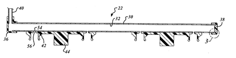
- FIG. 2 is a cross-sectional view illustrating a fuel rail having components coupled together using a method in accordance with the present invention.
- FIG. 3 is an enlarged view of a portion of FIG. 2 .
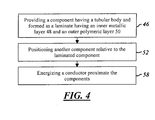
- FIG. 4 is a flow chart illustrating a method in accordance with the present invention.
- FIG. 1 illustrates a vehicle fuel system 10 .
- System 10 is particularly adapted for use in an automobile or light truck, but it should be understood that the inventive method described herein could be used for fuel systems on other types of vehicles and in a variety of fluid handling systems for vehicular and non-vehicular applications.
- System 10 is provided to store and transport fuel for use in internal combustion engine 12 .
- System 10 may include a filler neck assembly 14 , a fuel tank 16 , fuel lines 18 , a fuel pump 20 , fuel rail 22 and fuel injectors (not shown).
- Filler neck assembly 14 is provided to deliver fuel to the fuel tank 16 .
- Filler neck assembly 14 may include a cup assembly 24 configured to receive a fuel nozzle, a neck 26 for transferring fuel from cup assembly 24 to fuel tank 16 , and a side tube 28 to allow displaced vapors in fuel tank 16 to be vented during refueling.
- Filler neck assembly 14 is described in greater detail in the commonly-assigned U.S. patent application titled “Plastic Coated Metal Filler Neck Assembly” filed on Jan. 25, 2004 and naming David Stieler and Dale Sleep as inventors, the entire disclosure of which is incorporated herein by reference.
- Fuel tank 16 provides a reservoir for storage of fuel.
- Fuel tank 16 is conventional in the art. The size and shape of fuel tank 16 may vary in accordance with design considerations for the vehicle in which fuel tank 16 is located.
- Fuel tank 16 is in fluid communication with neck 26 and side tube 28 of filler neck assembly 14 and supply and return fuel lines 18 .
- Fuel lines 18 are provided to transport fuel between fuel tank 16 , pump 20 and fuel rail 22 .
- Fuel lines 18 are conventional in the art and are generally tubular in shape.
- Fuel lines 18 are made from metals and metal alloys such as steel or from plastics or a combination of metals, metal alloys and plastics.
- Pump 20 provides a means for causing fluid to flow within fuel system 10 .
- Pump 20 is conventional in the art and may be disposed between fuel tank 16 and fuel rail 22 , preferably in the supply fuel line.
- Fuel rail 22 provides a local fluid reservoir and a means for mounting of, and fuel delivery to, fuel injectors (not shown).
- rail 22 may include an elongate tubular body 30 defining a fluid chamber 32 and a plurality of fuel injector ports 34 .
- Rail 22 may include end caps 36 , 38 at either longitudinal end, an inlet tube 40 coupled to fuel line 18 , fuel injector pods 42 and mounting brackets 44 .
- Fuel rail 22 is described in greater detail in the commonly-assigned U.S. patent application titled “Plastic Coated Metal Fuel Rail” filed on Jan. 25, 2004 and naming David Stieler and Dale Sleep as inventors, the entire disclosure of which is incorporated herein by reference.
- the method includes the step 46 of providing a component having a tubular body and defining a fluid passageway that is formed as a laminate having an inner metallic layer and an outer polymeric layer.
- This component may, for example, comprise neck 26 or side tube 28 of filler neck assembly 14 , fuel line 18 , or body 30 of fuel rail 22 .
- the component has a tubular body (e.g., body 30 of fuel rail 22 in FIGS. 2-3 ).
- the component defines a fluid passageway (e.g., fluid chamber 32 in body 30 ) in which fuel or another fluid may be stored and/or through which fuel or another fluid may be transported. Referring to FIG.
- the component includes inner and outer layers 48 , 50 .
- inner and outer layers 48 , 50 are intended to refer to the juxtaposition of layer 48 relative to layer 50 . It should be understood that additional laminate layers may be formed inwardly of inner layer 48 or between inner and outer layers 48 , 50 and that either of layers 48 , 50 may include a plurality of sublayers without departing from the spirit of the present invention.
- Inner layer 48 is metallic.
- Layer 48 may comprise steel.
- layer 48 comprises aluminum.
- Outer layer 50 is polymeric and may comprise a plastic and, in particular, a thermoplastic. Outer layer 50 may or may not include a metallic or carbon or other non-metallic filler.
- outer layer 50 comprises nylon.
- Nylon refers to a family of polyamides generally characterized by the presence of the amide group, —CONH.
- the nylon is of a type known as nylon 12. It should be understood, however, that the type of nylon may vary and may be conductive (e.g., through the addition of carbon black) or non-conductive.
- Outer layer 40 may be pre-bonded to the inner layer 38 and may be extruded over the inner layer 38 .
- the component is formed from nylon coated aluminum tubing sold under the registered trademark “HYCOT” by Hydro Aluminum Hycot USA, Inc.
- the aluminum inner layer of the tubing has a thickness of about 0.1 to about 1.2 mm.
- the nylon outer layer of the tubing has a thickness of between about 80 and about 500 microns and may measure about 150 microns.
- the method may continue with the step 52 of positioning another component relative to the component described above.
- the second component may comprise, for example, cup assembly 24 , side tube 28 , a grounding strap or a flexible coupling between neck 26 and tank 16 .
- the first component comprises body 30 of fuel rail 22
- the second component may, for example, comprise an end cap 36 or 38 , inlet tube 40 , a valve, a fuel injector pod 42 or a mounting bracket 44 as shown in FIGS. 2-3 .
- step 52 may include the substep of aligning fluid apertures 54 , 56 in the two components for a purpose described hereinbelow.
- the method may continue with the step 58 of energizing a conductor, such as a coil, proximate the two components (e.g., body 30 and end cap 38 shown in FIG. 3 ) in a form of induction welding.
- a conductor such as a coil
- the inventors herein have recognized that the resulting electromagnetic field providing inductive energy to the inner layer 48 of the laminated component will result in heat transfer to outer layer 50 and, at sufficient levels, will result in deformation of outer layer 50 through melting. Referring to FIG. 3 , this action bonds the two components by forming a joint 60 between the two components that has significant strength. In fact, testing has shown that joint 60 is stronger than even the metallic inner layer 48 of the laminated component when submitted to pressure, pull and twist forces.
- the joint 60 also forms a hermetic seal such that fluid handling components may have fluid inlets and outlets sealingly coupled as shown in FIG. 2 (see fluid apertures 54 , 56 ).
- fluid handling components may have fluid inlets and outlets sealingly coupled as shown in FIG. 2 (see fluid apertures 54 , 56 ).
- step 52 e.g., end caps 36 and 38 relative to body 30 of fuel rail 22
- joints formed substantially simultaneously in step 58 allowing for slight time variation in formation of the bonds for components made from different materials.
- multiple components could be joined sequentially rather than substantially simultaneously.
- the formation of multiple joints may involve the use of multiple conductors to create induction heat welds at multiple locations.
- the components being bonded to the laminated component may be made from a variety of materials. End caps 36 , 38 and pods 42 may be made from plastics, for example.
- the inventors have discovered that metallic components, and particularly aluminum components, can be bonded in the same manner.
- the bond integrity between the aluminum component and the laminated component may be optionally improved by preconditioning of the surfaces of the aluminum component. Suitable conditioning treatments may include chemical etching by caustic or acid solutions, or by mechanical roughening or machining, including machined features such as ridges that may promote penetration of the mating polymeric material during heating and laminate deformation.
- a mechanical lip or stop or radial bend may be provided which is for example, bent over or formed within the connection after or during step 58 .
- These mechanical structures resist high pressure stresses and/or shift bending stresses away from the joint.
- the structure could be formed in the laminated component and received within a corresponding recess in the metallic component.
- the inventive method has several advantages for fitting to line connections as compared to traditionally brazed aluminum connections for use in fluid handling applications such as aluminum fuel lines or fuel cooling, air-conditioning lines, power steering lines, and engine cooling or oil cooling applications.
- the laminated tubing described herein can be used without the otherwise prohibitive temperatures involved in brazing (that would destroy the plastic coating).
- high strength aluminum fittings such as AA 6XXX, 5XXX or 7XXX alloys
- These alloys are difficult to use in conventional “CAB” or NocolokTM fluoride salt flux type brazing (whether furnace, flame or induction brazing) because the process limits the addition of Magnesium strengthening additions in the aluminum alloy that otherwise poison the flouride flux, or the temperature limits of the alloy (7xxx for example) are to low for conventional brazing.
- a method in accordance with the present invention has significant advantages relative to conventional manufacturing methods for fuel system components.
- the joints 60 formed by the inventive method are formed rapidly-typically in under one (1) minute as compared to the typical 15-40 minutes required for a brazing operation.
- the inventive method also does not require the significant energy use, precise control of temperature and furnace atmosphere conditions or considerable processing time of a furnace brazing operation.
- the appearance and composition of the component eliminates the need for plating and/or painting of the component prior to shipping to the customer, since the external surfaces that are normally exposed to the ambient environment—including the bonded joint itself—are completely covered by the polymer laminate coating.
Landscapes
- Engineering & Computer Science (AREA)
- Mechanical Engineering (AREA)
- Cooling, Air Intake And Gas Exhaust, And Fuel Tank Arrangements In Propulsion Units (AREA)
- Fuel-Injection Apparatus (AREA)
Abstract
Description
- 1. Field of the Invention
- This invention relates to methods for coupling two or more components and, in particular, to a method for coupling components of, but not limited to, a vehicle fuel delivery system and providing a fluid tight, pressurized joint.
- 2. Discussion of Related Art
- A conventional vehicle fuel system for use with a fuel injected internal combustion engine includes a filler neck assembly, a fuel tank, fuel lines, one or more fuel rails and fuel injectors. Fuel is input to the tank through the filler neck assembly (e.g., a fuel station). Fuel is supplied from the fuel tank to the fuel rail through the fuel lines where electronically controlled fuel injectors output fuel to the combustion chambers of the engine.
- Manufacturing of conventional fuel system components is an expensive and time-consuming process. Many components are formed from metal alloys such as steel (although some fuel and vapor lines have been made using plastic coated aluminum). A conventional fuel rail might have numerous components to couple together including a tubular rail, end caps, an inlet tube, mounting brackets and fuel injector cups. The brackets and cups are typically pre-staked to the tubular rail and holes are drilled through the cups. The caps, inlet tube, mounting brackets and cups are then brazed to the tubular rail. The assembly is fed through a brazing furnace to braze the various joints and is then cooled before testing, packaging and shipping. For aesthetics, corrosion resistance, and other reasons, some assembled rails are also commonly subjected to plating or the application of a protective or reflective coating. The above-described process is, again, expensive and time-consuming. The heat requirements of the brazing furnace necessitate significant energy use and precise control of temperature and furnace atmosphere conditions. The brazing process itself also typically takes a relatively high amount of time (approximately 40 minutes for one conventional fuel rail).
- Hydro Aluminum Hycot USA Inc. has previously developed a nylon coated aluminum tube sold under the registered trademark “HYCOT” for use in various fluid handling applications including finished fuel lines. Further, Hydro Aluminum Hycot USA, Inc. has coupled other components to such tubes using an ultrasonic welding process. These components have been limited, however, to plastic brackets not involved in fuel transport and not requiring a fluid tight, pressurized joint.
- The inventors herein have recognized a need for a method for coupling components in a fluid handling system that will minimize and/or eliminate one or more of the above-identified deficiencies. The inventors herein have particularly recognized the ability to form a fuel system component as a laminated structure such as the “HYCOT” tubing and to couple other components to that component in such a way as to form a strong, fluid tight joint that is capable of withstanding pressurized applications without the need for complex mechanical seals while simultaneously reducing the cost and time of conventional manufacturing processes such as brazing or plastic injection molding.
- The present invention relates to a method for coupling first and second components of a fluid handling system.
- A method in accordance with the present invention includes the step of providing the first component, the first component including a tubular body defining a fluid passageway and formed as a laminate having an inner metallic layer and an outer polymeric layer. The component may, for example, comprise a fuel filler neck or a fuel rail. The method further includes the step of positioning the second component relative to the first component. This step may include the substep of aligning fluid apertures in the first and second components. The method further includes the step of energizing a conductor proximate the first and second components to generate heat transfer from the inner layer of the first component to the outer layer of the first component to deform the outer layer of the first component and bond the second component to the first component.
- A method in accordance with the present invention has significant advantages relative to conventional manufacturing methods for fuel system components. The bonded joints for the parts of a fuel rail or other component can be formed in under one (1) minute as compared to the typical 15-40 minutes required for a furnace brazing operation. Moreover, the process does not require the significant energy use, precise control of temperature and furnace atmosphere conditions or considerable processing time of a furnace brazing operation. Further, the appearance and composition of the component eliminates the need for plating and/or painting of the component prior to shipping to the customer, since the external surfaces that are normally exposed to the ambient environment—including the bonded joint itself—are completely covered by the polymer laminate coating.
- These and other advantages of this invention will become apparent to one skilled in the art from the following detailed description and the accompanying drawings illustrating features of this invention by way of example.
-
FIG. 1 is a diagrammatic view of a vehicle fuel system. -
FIG. 2 is a cross-sectional view illustrating a fuel rail having components coupled together using a method in accordance with the present invention. -
FIG. 3 is an enlarged view of a portion ofFIG. 2 . -
FIG. 4 is a flow chart illustrating a method in accordance with the present invention. - Referring now to the drawings wherein like reference numerals are used to identify identical components in the various views,
FIG. 1 illustrates avehicle fuel system 10.System 10 is particularly adapted for use in an automobile or light truck, but it should be understood that the inventive method described herein could be used for fuel systems on other types of vehicles and in a variety of fluid handling systems for vehicular and non-vehicular applications.System 10 is provided to store and transport fuel for use ininternal combustion engine 12.System 10 may include afiller neck assembly 14, afuel tank 16,fuel lines 18, afuel pump 20,fuel rail 22 and fuel injectors (not shown). -
Filler neck assembly 14 is provided to deliver fuel to thefuel tank 16.Filler neck assembly 14 may include a cup assembly 24 configured to receive a fuel nozzle, aneck 26 for transferring fuel from cup assembly 24 tofuel tank 16, and aside tube 28 to allow displaced vapors infuel tank 16 to be vented during refueling.Filler neck assembly 14 is described in greater detail in the commonly-assigned U.S. patent application titled “Plastic Coated Metal Filler Neck Assembly” filed on Jan. 25, 2004 and naming David Stieler and Dale Sleep as inventors, the entire disclosure of which is incorporated herein by reference. -
Fuel tank 16 provides a reservoir for storage of fuel.Fuel tank 16 is conventional in the art. The size and shape offuel tank 16 may vary in accordance with design considerations for the vehicle in whichfuel tank 16 is located.Fuel tank 16 is in fluid communication withneck 26 andside tube 28 offiller neck assembly 14 and supply andreturn fuel lines 18. -
Fuel lines 18 are provided to transport fuel betweenfuel tank 16,pump 20 andfuel rail 22.Fuel lines 18 are conventional in the art and are generally tubular in shape.Fuel lines 18 are made from metals and metal alloys such as steel or from plastics or a combination of metals, metal alloys and plastics. -
Pump 20 provides a means for causing fluid to flow withinfuel system 10.Pump 20 is conventional in the art and may be disposed betweenfuel tank 16 andfuel rail 22, preferably in the supply fuel line. -
Fuel rail 22 provides a local fluid reservoir and a means for mounting of, and fuel delivery to, fuel injectors (not shown). Referring toFIGS. 2-3 ,rail 22 may include an elongate tubular body 30 defining afluid chamber 32 and a plurality of fuel injector ports 34.Rail 22 may includeend caps inlet tube 40 coupled tofuel line 18,fuel injector pods 42 and mounting brackets 44.Fuel rail 22 is described in greater detail in the commonly-assigned U.S. patent application titled “Plastic Coated Metal Fuel Rail” filed on Jan. 25, 2004 and naming David Stieler and Dale Sleep as inventors, the entire disclosure of which is incorporated herein by reference. - Referring now to
FIG. 4 , a method in accordance with the present invention is described and illustrated. The method includes thestep 46 of providing a component having a tubular body and defining a fluid passageway that is formed as a laminate having an inner metallic layer and an outer polymeric layer. This component may, for example, compriseneck 26 orside tube 28 offiller neck assembly 14,fuel line 18, or body 30 offuel rail 22. The component has a tubular body (e.g., body 30 offuel rail 22 inFIGS. 2-3 ). The component defines a fluid passageway (e.g.,fluid chamber 32 in body 30) in which fuel or another fluid may be stored and/or through which fuel or another fluid may be transported. Referring toFIG. 3 (illustrating a portion of body 30 of fuel rail 22), the component includes inner andouter layers layer 48 relative to layer 50. It should be understood that additional laminate layers may be formed inwardly ofinner layer 48 or between inner andouter layers layers Inner layer 48 is metallic.Layer 48 may comprise steel. In apreferred embodiment layer 48 comprises aluminum.Outer layer 50 is polymeric and may comprise a plastic and, in particular, a thermoplastic.Outer layer 50 may or may not include a metallic or carbon or other non-metallic filler. In a preferred embodiment,outer layer 50 comprises nylon. Nylon refers to a family of polyamides generally characterized by the presence of the amide group, —CONH. In a preferred embodiment, the nylon is of a type known asnylon 12. It should be understood, however, that the type of nylon may vary and may be conductive (e.g., through the addition of carbon black) or non-conductive.Outer layer 40 may be pre-bonded to theinner layer 38 and may be extruded over theinner layer 38. In one constructed embodiment, the component is formed from nylon coated aluminum tubing sold under the registered trademark “HYCOT” by Hydro Aluminum Hycot USA, Inc. The aluminum inner layer of the tubing has a thickness of about 0.1 to about 1.2 mm. The nylon outer layer of the tubing has a thickness of between about 80 and about 500 microns and may measure about 150 microns. - Referring again to
FIG. 4 , the method may continue with thestep 52 of positioning another component relative to the component described above. Where the first component comprises aneck 26 ofassembly 14, the second component may comprise, for example, cup assembly 24,side tube 28, a grounding strap or a flexible coupling betweenneck 26 andtank 16. Where the first component comprises body 30 offuel rail 22, the second component may, for example, comprise anend cap inlet tube 40, a valve, afuel injector pod 42 or a mounting bracket 44 as shown inFIGS. 2-3 . As shown inFIG. 2 , step 52 may include the substep of aligningfluid apertures - The method may continue with the
step 58 of energizing a conductor, such as a coil, proximate the two components (e.g., body 30 andend cap 38 shown inFIG. 3 ) in a form of induction welding. The inventors herein have recognized that the resulting electromagnetic field providing inductive energy to theinner layer 48 of the laminated component will result in heat transfer toouter layer 50 and, at sufficient levels, will result in deformation ofouter layer 50 through melting. Referring toFIG. 3 , this action bonds the two components by forming a joint 60 between the two components that has significant strength. In fact, testing has shown that joint 60 is stronger than even the metallicinner layer 48 of the laminated component when submitted to pressure, pull and twist forces. The joint 60 also forms a hermetic seal such that fluid handling components may have fluid inlets and outlets sealingly coupled as shown inFIG. 2 (seefluid apertures 54, 56). Although the above description referred to formation of a single joint, it should be understood that multiple joints could be formed substantially simultaneously. In particular, multiple components could be positioned in step 52 (e.g., end caps 36 and 38 relative to body 30 of fuel rail 22) and joints formed substantially simultaneously in step 58 (allowing for slight time variation in formation of the bonds for components made from different materials). Alternatively, multiple components could be joined sequentially rather than substantially simultaneously. The formation of multiple joints may involve the use of multiple conductors to create induction heat welds at multiple locations. Further, it should be understood that the components being bonded to the laminated component may be made from a variety of materials. End caps 36, 38 andpods 42 may be made from plastics, for example. Alternatively, the inventors have discovered that metallic components, and particularly aluminum components, can be bonded in the same manner. In this case, the bond integrity between the aluminum component and the laminated component may be optionally improved by preconditioning of the surfaces of the aluminum component. Suitable conditioning treatments may include chemical etching by caustic or acid solutions, or by mechanical roughening or machining, including machined features such as ridges that may promote penetration of the mating polymeric material during heating and laminate deformation. In particular, a mechanical lip or stop or radial bend may be provided which is for example, bent over or formed within the connection after or duringstep 58. These mechanical structures resist high pressure stresses and/or shift bending stresses away from the joint. The structure could be formed in the laminated component and received within a corresponding recess in the metallic component. The inventive method has several advantages for fitting to line connections as compared to traditionally brazed aluminum connections for use in fluid handling applications such as aluminum fuel lines or fuel cooling, air-conditioning lines, power steering lines, and engine cooling or oil cooling applications. First, the laminated tubing described herein can be used without the otherwise prohibitive temperatures involved in brazing (that would destroy the plastic coating). Second, high strength aluminum fittings (such as AA 6XXX, 5XXX or 7XXX alloys) can be used in the inventive method. These alloys are difficult to use in conventional “CAB” or Nocolok™ fluoride salt flux type brazing (whether furnace, flame or induction brazing) because the process limits the addition of Magnesium strengthening additions in the aluminum alloy that otherwise poison the flouride flux, or the temperature limits of the alloy (7xxx for example) are to low for conventional brazing. - A method in accordance with the present invention has significant advantages relative to conventional manufacturing methods for fuel system components. The joints 60 formed by the inventive method are formed rapidly-typically in under one (1) minute as compared to the typical 15-40 minutes required for a brazing operation. The inventive method also does not require the significant energy use, precise control of temperature and furnace atmosphere conditions or considerable processing time of a furnace brazing operation. Further, the appearance and composition of the component eliminates the need for plating and/or painting of the component prior to shipping to the customer, since the external surfaces that are normally exposed to the ambient environment—including the bonded joint itself—are completely covered by the polymer laminate coating.
- While the invention has been shown and described with reference to one or more particular embodiments thereof, it will be understood by those of skill in the art that various changes and modifications can be made without departing from the spirit and scope of the invention.
Claims (13)
Priority Applications (2)
| Application Number | Priority Date | Filing Date | Title |
|---|---|---|---|
| US11/042,014 US20060163243A1 (en) | 2005-01-25 | 2005-01-25 | Method of coupling fuel system components |
| PCT/US2006/002497 WO2006081247A1 (en) | 2005-01-25 | 2006-01-25 | Method of coupling fuel system components |
Applications Claiming Priority (1)
| Application Number | Priority Date | Filing Date | Title |
|---|---|---|---|
| US11/042,014 US20060163243A1 (en) | 2005-01-25 | 2005-01-25 | Method of coupling fuel system components |
Publications (1)
| Publication Number | Publication Date |
|---|---|
| US20060163243A1 true US20060163243A1 (en) | 2006-07-27 |
Family
ID=36384494
Family Applications (1)
| Application Number | Title | Priority Date | Filing Date |
|---|---|---|---|
| US11/042,014 Abandoned US20060163243A1 (en) | 2005-01-25 | 2005-01-25 | Method of coupling fuel system components |
Country Status (2)
| Country | Link |
|---|---|
| US (1) | US20060163243A1 (en) |
| WO (1) | WO2006081247A1 (en) |
Cited By (11)
| Publication number | Priority date | Publication date | Assignee | Title |
|---|---|---|---|---|
| US20060162697A1 (en) * | 2005-01-25 | 2006-07-27 | Stieler David C | Plastic coated metal fuel rail |
| US20060249213A1 (en) * | 2005-04-21 | 2006-11-09 | Stieler David C | Plastic coated metal heater and water tube assembly |
| US20070042148A1 (en) * | 2005-08-19 | 2007-02-22 | Stieler David C | Tether attachment to plastic coated metal tubing |
| US20070095467A1 (en) * | 2005-10-31 | 2007-05-03 | Stieler David C | Method for joining tubular bodies with a connector |
| US20080028592A1 (en) * | 2005-09-30 | 2008-02-07 | Stieler David C | Method of coupling plastic components to metal tubing |
| US20100116480A1 (en) * | 2008-08-29 | 2010-05-13 | Ti Group Automotive Systems, Llc | Vehicular climate control system |
| US20120138020A1 (en) * | 2009-08-11 | 2012-06-07 | Kefico Corporation | Mounting structure for a direct injection fuel rail |
| US20150198128A1 (en) * | 2012-07-23 | 2015-07-16 | Continental Automotive Gmbh | Fuel Rail Assembly |
| US11156194B2 (en) * | 2016-08-25 | 2021-10-26 | Usui Co., Ltd. | End cap |
| US20220009345A1 (en) * | 2020-07-09 | 2022-01-13 | Magna Energy Storage Systems Gesmbh | Fuel tank device |
| WO2023042800A1 (en) * | 2021-09-14 | 2023-03-23 | 三桜工業株式会社 | Fuel distribution pipe |
Citations (31)
| Publication number | Priority date | Publication date | Assignee | Title |
|---|---|---|---|---|
| US4234781A (en) * | 1977-12-19 | 1980-11-18 | Birger Flink | Method and arrangement for heat-welding together two tubular elements |
| US4548338A (en) * | 1982-10-29 | 1985-10-22 | Automation Industrielle, S.A. | Packing tube |
| US4758455A (en) * | 1985-07-10 | 1988-07-19 | Handy & Harman Automotive Group Inc. | Composite fuel and vapor tube having increased heat resistance |
| US5036889A (en) * | 1989-04-10 | 1991-08-06 | J. L. Clark, Inc. | Tube with flip-top cap |
| US5129544A (en) * | 1990-11-08 | 1992-07-14 | Jacobson Wendell L | Laminated fuel tank structure |
| US5198053A (en) * | 1988-10-18 | 1993-03-30 | Mather Seal Company | Method and apparatus for bonding polytetrafluoroethylene to a metal substrate and articles thereby produced |
| US5590691A (en) * | 1994-05-02 | 1997-01-07 | Itt Corporation | Extruded multiple plastic layer coating bonded to a metal tube |
| US5681518A (en) * | 1995-03-15 | 1997-10-28 | Handy & Harman Automotive Group | Process for molding a fuel rail assembly |
| US5919387A (en) * | 1996-04-03 | 1999-07-06 | The United States Of America As Represented By The United States National Aeronautics And Space Administration | Inductive systems for bonding and joining pipes |
| US5932306A (en) * | 1995-04-24 | 1999-08-03 | Usui Kokusai Sangyo Kaisha Limited | Corrosion-and-chipping-resistant resin coating structure for stainless steel pipes |
| US5972450A (en) * | 1995-10-10 | 1999-10-26 | Bundy Corporation | Metal tubing coated with multiple layers of polymeric materials |
| US5992898A (en) * | 1997-08-21 | 1999-11-30 | Echlin, Inc. | Quick-connect assembly and method of manufacture |
| US6012743A (en) * | 1996-06-10 | 2000-01-11 | Hutchinson | Quick connection device for fluid conduit under pressure |
| US6240970B1 (en) * | 1999-04-01 | 2001-06-05 | Itt Manufacturing Enterprises, Inc. | Tubing for handling hydrocarbon materials and having an outer jacket layer adhered thereto |
| US6269804B1 (en) * | 2000-04-26 | 2001-08-07 | Delphi Technologies, Inc. | Coaxial liquid cooled fuel rail assembly |
| US6276400B1 (en) * | 1999-06-08 | 2001-08-21 | Itt Manufacturing Enterprises, Inc. | Corrosion resistant powder coated metal tube and process for making the same |
| US6308992B1 (en) * | 1998-07-15 | 2001-10-30 | Toyoda Gosei Co., Ltd. | Hose connecting assembly |
| US6308686B1 (en) * | 1999-11-18 | 2001-10-30 | Siemens Canada Limited | Intake manifold with internal fuel rail and injectors |
| US6341597B1 (en) * | 1998-11-03 | 2002-01-29 | Siemens Automotive Corporation | Fuel injection system for high vapor pressure liquid fuel |
| US6408890B1 (en) * | 1999-10-26 | 2002-06-25 | Tokai Rubber Industries, Ltd. | Hose connecting structure |
| US6422396B1 (en) * | 1999-09-16 | 2002-07-23 | Kaydon Custom Filtration Corporation | Coalescer for hydrocarbons containing surfactant |
| US6541559B2 (en) * | 2000-05-24 | 2003-04-01 | Ube Industries, Ltd. | Polyamide resin composition showing excellent weld strength |
| US6588459B2 (en) * | 1999-12-03 | 2003-07-08 | Shelby Enterprises, Inc. | Fuel tank filler neck and method of manufacturing same |
| US6626152B1 (en) * | 2000-09-19 | 2003-09-30 | Delphi Technologies, Inc. | Fuel rail |
| US6652939B2 (en) * | 2001-09-13 | 2003-11-25 | Dayco Products, Llc | Low permeation nylon tube with aluminum barrier layer |
| US20040142135A1 (en) * | 2003-01-21 | 2004-07-22 | 3M Innovative Properties Company | Fuel management system comprising a fluoroelastomer layer having a hydrotalcite compound |
| US6773047B2 (en) * | 2002-02-08 | 2004-08-10 | Multimatic, Inc. | Lift assist mechanism for vehicle tailgates |
| US6832785B1 (en) * | 2003-07-21 | 2004-12-21 | Itt Manufacturing Enterprises, Inc. | Spin welded fluid coupling |
| US6974614B2 (en) * | 2001-09-13 | 2005-12-13 | Dayco Products, Llc | Low permeation high density polyethylene tube with aluminum barrier layer |
| US20060162697A1 (en) * | 2005-01-25 | 2006-07-27 | Stieler David C | Plastic coated metal fuel rail |
| US20060249213A1 (en) * | 2005-04-21 | 2006-11-09 | Stieler David C | Plastic coated metal heater and water tube assembly |
Family Cites Families (4)
| Publication number | Priority date | Publication date | Assignee | Title |
|---|---|---|---|---|
| JPS63215427A (en) * | 1987-03-03 | 1988-09-07 | Yamakawa Kogyo Kk | resin tank |
| JPH05196187A (en) * | 1992-01-21 | 1993-08-06 | Sekisui Chem Co Ltd | How to connect pipes and fittings |
| DE19636670A1 (en) * | 1996-09-10 | 1998-03-12 | Gea Waerme Und Umwelttechnik G | Process for the welding connection of a heat exchanger tube with a plastic film |
| EP1510746A1 (en) * | 2003-08-26 | 2005-03-02 | Glynwed Pipe Systems Limited | Method for joining multi-layered pipe |
-
2005
- 2005-01-25 US US11/042,014 patent/US20060163243A1/en not_active Abandoned
-
2006
- 2006-01-25 WO PCT/US2006/002497 patent/WO2006081247A1/en not_active Ceased
Patent Citations (33)
| Publication number | Priority date | Publication date | Assignee | Title |
|---|---|---|---|---|
| US4234781A (en) * | 1977-12-19 | 1980-11-18 | Birger Flink | Method and arrangement for heat-welding together two tubular elements |
| US4548338A (en) * | 1982-10-29 | 1985-10-22 | Automation Industrielle, S.A. | Packing tube |
| US4758455A (en) * | 1985-07-10 | 1988-07-19 | Handy & Harman Automotive Group Inc. | Composite fuel and vapor tube having increased heat resistance |
| US5198053A (en) * | 1988-10-18 | 1993-03-30 | Mather Seal Company | Method and apparatus for bonding polytetrafluoroethylene to a metal substrate and articles thereby produced |
| US5036889A (en) * | 1989-04-10 | 1991-08-06 | J. L. Clark, Inc. | Tube with flip-top cap |
| US5129544A (en) * | 1990-11-08 | 1992-07-14 | Jacobson Wendell L | Laminated fuel tank structure |
| US5590691A (en) * | 1994-05-02 | 1997-01-07 | Itt Corporation | Extruded multiple plastic layer coating bonded to a metal tube |
| US5681518A (en) * | 1995-03-15 | 1997-10-28 | Handy & Harman Automotive Group | Process for molding a fuel rail assembly |
| US5932306A (en) * | 1995-04-24 | 1999-08-03 | Usui Kokusai Sangyo Kaisha Limited | Corrosion-and-chipping-resistant resin coating structure for stainless steel pipes |
| US5972450A (en) * | 1995-10-10 | 1999-10-26 | Bundy Corporation | Metal tubing coated with multiple layers of polymeric materials |
| US5919387A (en) * | 1996-04-03 | 1999-07-06 | The United States Of America As Represented By The United States National Aeronautics And Space Administration | Inductive systems for bonding and joining pipes |
| US6012743A (en) * | 1996-06-10 | 2000-01-11 | Hutchinson | Quick connection device for fluid conduit under pressure |
| US5992898A (en) * | 1997-08-21 | 1999-11-30 | Echlin, Inc. | Quick-connect assembly and method of manufacture |
| US6308992B1 (en) * | 1998-07-15 | 2001-10-30 | Toyoda Gosei Co., Ltd. | Hose connecting assembly |
| US6341597B1 (en) * | 1998-11-03 | 2002-01-29 | Siemens Automotive Corporation | Fuel injection system for high vapor pressure liquid fuel |
| US6240970B1 (en) * | 1999-04-01 | 2001-06-05 | Itt Manufacturing Enterprises, Inc. | Tubing for handling hydrocarbon materials and having an outer jacket layer adhered thereto |
| US6276400B1 (en) * | 1999-06-08 | 2001-08-21 | Itt Manufacturing Enterprises, Inc. | Corrosion resistant powder coated metal tube and process for making the same |
| US6528125B1 (en) * | 1999-06-08 | 2003-03-04 | Itt Manufacturing Enterprises, Inc. | Corrosion resistant powder coated metal tube and process for making the same |
| US6422396B1 (en) * | 1999-09-16 | 2002-07-23 | Kaydon Custom Filtration Corporation | Coalescer for hydrocarbons containing surfactant |
| US6408890B1 (en) * | 1999-10-26 | 2002-06-25 | Tokai Rubber Industries, Ltd. | Hose connecting structure |
| US6308686B1 (en) * | 1999-11-18 | 2001-10-30 | Siemens Canada Limited | Intake manifold with internal fuel rail and injectors |
| US6588459B2 (en) * | 1999-12-03 | 2003-07-08 | Shelby Enterprises, Inc. | Fuel tank filler neck and method of manufacturing same |
| US6269804B1 (en) * | 2000-04-26 | 2001-08-07 | Delphi Technologies, Inc. | Coaxial liquid cooled fuel rail assembly |
| US6541559B2 (en) * | 2000-05-24 | 2003-04-01 | Ube Industries, Ltd. | Polyamide resin composition showing excellent weld strength |
| US6626152B1 (en) * | 2000-09-19 | 2003-09-30 | Delphi Technologies, Inc. | Fuel rail |
| US6652939B2 (en) * | 2001-09-13 | 2003-11-25 | Dayco Products, Llc | Low permeation nylon tube with aluminum barrier layer |
| US6974614B2 (en) * | 2001-09-13 | 2005-12-13 | Dayco Products, Llc | Low permeation high density polyethylene tube with aluminum barrier layer |
| US7052751B2 (en) * | 2001-09-13 | 2006-05-30 | Dayco Products, Llc | Low permeation nylon tube with aluminum barrier layer |
| US6773047B2 (en) * | 2002-02-08 | 2004-08-10 | Multimatic, Inc. | Lift assist mechanism for vehicle tailgates |
| US20040142135A1 (en) * | 2003-01-21 | 2004-07-22 | 3M Innovative Properties Company | Fuel management system comprising a fluoroelastomer layer having a hydrotalcite compound |
| US6832785B1 (en) * | 2003-07-21 | 2004-12-21 | Itt Manufacturing Enterprises, Inc. | Spin welded fluid coupling |
| US20060162697A1 (en) * | 2005-01-25 | 2006-07-27 | Stieler David C | Plastic coated metal fuel rail |
| US20060249213A1 (en) * | 2005-04-21 | 2006-11-09 | Stieler David C | Plastic coated metal heater and water tube assembly |
Cited By (16)
| Publication number | Priority date | Publication date | Assignee | Title |
|---|---|---|---|---|
| US20060162697A1 (en) * | 2005-01-25 | 2006-07-27 | Stieler David C | Plastic coated metal fuel rail |
| US7263975B2 (en) * | 2005-01-25 | 2007-09-04 | Dana Corporation | Plastic coated metal fuel rail |
| US20060249213A1 (en) * | 2005-04-21 | 2006-11-09 | Stieler David C | Plastic coated metal heater and water tube assembly |
| US20070042148A1 (en) * | 2005-08-19 | 2007-02-22 | Stieler David C | Tether attachment to plastic coated metal tubing |
| US20080028592A1 (en) * | 2005-09-30 | 2008-02-07 | Stieler David C | Method of coupling plastic components to metal tubing |
| US20070095467A1 (en) * | 2005-10-31 | 2007-05-03 | Stieler David C | Method for joining tubular bodies with a connector |
| US8360476B2 (en) | 2008-08-29 | 2013-01-29 | Ti Group Automotive Systems, Llc | Vehicular climate control system |
| US20100116480A1 (en) * | 2008-08-29 | 2010-05-13 | Ti Group Automotive Systems, Llc | Vehicular climate control system |
| US20120138020A1 (en) * | 2009-08-11 | 2012-06-07 | Kefico Corporation | Mounting structure for a direct injection fuel rail |
| US8944031B2 (en) * | 2009-08-11 | 2015-02-03 | Kefico Corporation | Mounting structure for a direct injection fuel rail |
| US20150198128A1 (en) * | 2012-07-23 | 2015-07-16 | Continental Automotive Gmbh | Fuel Rail Assembly |
| US10132282B2 (en) * | 2012-07-23 | 2018-11-20 | Continental Automotive Gmbh | Fuel rail assembly |
| US11156194B2 (en) * | 2016-08-25 | 2021-10-26 | Usui Co., Ltd. | End cap |
| US20220009345A1 (en) * | 2020-07-09 | 2022-01-13 | Magna Energy Storage Systems Gesmbh | Fuel tank device |
| US11660954B2 (en) * | 2020-07-09 | 2023-05-30 | Magna Energy Storage Systems Gesmbh | Fuel tank device |
| WO2023042800A1 (en) * | 2021-09-14 | 2023-03-23 | 三桜工業株式会社 | Fuel distribution pipe |
Also Published As
| Publication number | Publication date |
|---|---|
| WO2006081247A1 (en) | 2006-08-03 |
Similar Documents
| Publication | Publication Date | Title |
|---|---|---|
| CN102052218B (en) | Fuel distributor | |
| US20060163243A1 (en) | Method of coupling fuel system components | |
| US8596246B2 (en) | Fuel rail for high-pressure direct-injection internal combustion engines and method for manufacturing thereof | |
| US6447020B1 (en) | High-pressure integral tube coupling arrangements | |
| US20030102668A1 (en) | Method of hydroforming articles and the articles formed thereby | |
| US20060162144A1 (en) | Method of coupling fuel system components | |
| US20080169364A1 (en) | Welded fuel injector attachment | |
| US8360476B2 (en) | Vehicular climate control system | |
| US20170226978A1 (en) | Fuel Rail | |
| US20080028592A1 (en) | Method of coupling plastic components to metal tubing | |
| US20070023129A1 (en) | Method of coupling polymeric tubing to polymeric coated metal tubing | |
| US20060249213A1 (en) | Plastic coated metal heater and water tube assembly | |
| US6915820B2 (en) | Automotive fluid tubing, especially for fuel and hydraulic fluid | |
| US6851723B2 (en) | Ring joint, connection structure for connecting piping and ring joint, and method of connecting ring joint and piping | |
| US20070095467A1 (en) | Method for joining tubular bodies with a connector | |
| US7258108B2 (en) | Fuel injection rail | |
| JPH07112485A (en) | How to connect composite pipes | |
| US20130312943A1 (en) | Process for producing an integral bond | |
| KR20100010657A (en) | Filler tube assembly for automobile and methods of making the same | |
| JP4756804B2 (en) | Connection structure and connection method between metal tube and eye joint | |
| JP4587434B2 (en) | Connection structure between thin metal pipe and resin flexible hose | |
| JP2004100811A (en) | Eye joint, connecting structure between eye joint and pipe and its method | |
| US20070042148A1 (en) | Tether attachment to plastic coated metal tubing | |
| JPH08145249A (en) | Al alloy pipe joint structure with excellent airtight durability | |
| WO2006101914A1 (en) | Electromagnetic forming crimp |
Legal Events
| Date | Code | Title | Description |
|---|---|---|---|
| AS | Assignment |
Owner name: DANA CORPORATION, OHIO Free format text: ASSIGNMENT OF ASSIGNORS INTEREST;ASSIGNORS:STEILER, DAVID C.;SLEEP, DALE L.;CHEADLE, BRIAN;REEL/FRAME:016223/0841 Effective date: 20050125 |
|
| AS | Assignment |
Owner name: DANA AUTOMOTIVE SYSTEMS GROUP, LLC, OHIO Free format text: ASSIGNMENT OF ASSIGNORS INTEREST;ASSIGNOR:DANA CORPORATION;REEL/FRAME:020540/0476 Effective date: 20080131 Owner name: DANA AUTOMOTIVE SYSTEMS GROUP, LLC,OHIO Free format text: ASSIGNMENT OF ASSIGNORS INTEREST;ASSIGNOR:DANA CORPORATION;REEL/FRAME:020540/0476 Effective date: 20080131 |
|
| AS | Assignment |
Owner name: CITICORP USA, INC., NEW YORK Free format text: INTELLECTUAL PROPERTY REVOLVING FACILITY SECURITY AGREEMENT;ASSIGNORS:DANA HOLDING CORPORATION;DANA LIMITED;DANA AUTOMOTIVE SYSTEMS GROUP, LLC;AND OTHERS;REEL/FRAME:020859/0249 Effective date: 20080131 Owner name: CITICORP USA, INC.,NEW YORK Free format text: INTELLECTUAL PROPERTY REVOLVING FACILITY SECURITY AGREEMENT;ASSIGNORS:DANA HOLDING CORPORATION;DANA LIMITED;DANA AUTOMOTIVE SYSTEMS GROUP, LLC;AND OTHERS;REEL/FRAME:020859/0249 Effective date: 20080131 Owner name: CITICORP USA, INC., NEW YORK Free format text: INTELLECTUAL PROPERTY TERM FACILITY SECURITY AGREEMENT;ASSIGNORS:DANA HOLDING CORPORATION;DANA LIMITED;DANA AUTOMOTIVE SYSTEMS GROUP, LLC;AND OTHERS;REEL/FRAME:020859/0359 Effective date: 20080131 Owner name: CITICORP USA, INC.,NEW YORK Free format text: INTELLECTUAL PROPERTY TERM FACILITY SECURITY AGREEMENT;ASSIGNORS:DANA HOLDING CORPORATION;DANA LIMITED;DANA AUTOMOTIVE SYSTEMS GROUP, LLC;AND OTHERS;REEL/FRAME:020859/0359 Effective date: 20080131 |
|
| STCB | Information on status: application discontinuation |
Free format text: ABANDONED -- FAILURE TO RESPOND TO AN OFFICE ACTION |