EP2465832B2 - Verfahren zur Herstellung einer reflexionsmindernden Beschichtung - Google Patents
Verfahren zur Herstellung einer reflexionsmindernden Beschichtung Download PDFInfo
- Publication number
- EP2465832B2 EP2465832B2 EP11193150.7A EP11193150A EP2465832B2 EP 2465832 B2 EP2465832 B2 EP 2465832B2 EP 11193150 A EP11193150 A EP 11193150A EP 2465832 B2 EP2465832 B2 EP 2465832B2
- Authority
- EP
- European Patent Office
- Prior art keywords
- laser
- plasma
- coating
- layer
- substrate
- Prior art date
- Legal status (The legal status is an assumption and is not a legal conclusion. Google has not performed a legal analysis and makes no representation as to the accuracy of the status listed.)
- Active
Links
Images
Classifications
-
- C—CHEMISTRY; METALLURGY
- C03—GLASS; MINERAL OR SLAG WOOL
- C03C—CHEMICAL COMPOSITION OF GLASSES, GLAZES OR VITREOUS ENAMELS; SURFACE TREATMENT OF GLASS; SURFACE TREATMENT OF FIBRES OR FILAMENTS MADE FROM GLASS, MINERALS OR SLAGS; JOINING GLASS TO GLASS OR OTHER MATERIALS
- C03C17/00—Surface treatment of glass, not in the form of fibres or filaments, by coating
- C03C17/001—General methods for coating; Devices therefor
- C03C17/002—General methods for coating; Devices therefor for flat glass, e.g. float glass
-
- C—CHEMISTRY; METALLURGY
- C03—GLASS; MINERAL OR SLAG WOOL
- C03C—CHEMICAL COMPOSITION OF GLASSES, GLAZES OR VITREOUS ENAMELS; SURFACE TREATMENT OF GLASS; SURFACE TREATMENT OF FIBRES OR FILAMENTS MADE FROM GLASS, MINERALS OR SLAGS; JOINING GLASS TO GLASS OR OTHER MATERIALS
- C03C17/00—Surface treatment of glass, not in the form of fibres or filaments, by coating
- C03C17/22—Surface treatment of glass, not in the form of fibres or filaments, by coating with other inorganic material
- C03C17/23—Oxides
-
- C—CHEMISTRY; METALLURGY
- C03—GLASS; MINERAL OR SLAG WOOL
- C03C—CHEMICAL COMPOSITION OF GLASSES, GLAZES OR VITREOUS ENAMELS; SURFACE TREATMENT OF GLASS; SURFACE TREATMENT OF FIBRES OR FILAMENTS MADE FROM GLASS, MINERALS OR SLAGS; JOINING GLASS TO GLASS OR OTHER MATERIALS
- C03C2217/00—Coatings on glass
- C03C2217/70—Properties of coatings
- C03C2217/73—Anti-reflective coatings with specific characteristics
- C03C2217/732—Anti-reflective coatings with specific characteristics made of a single layer
-
- C—CHEMISTRY; METALLURGY
- C03—GLASS; MINERAL OR SLAG WOOL
- C03C—CHEMICAL COMPOSITION OF GLASSES, GLAZES OR VITREOUS ENAMELS; SURFACE TREATMENT OF GLASS; SURFACE TREATMENT OF FIBRES OR FILAMENTS MADE FROM GLASS, MINERALS OR SLAGS; JOINING GLASS TO GLASS OR OTHER MATERIALS
- C03C2218/00—Methods for coating glass
- C03C2218/30—Aspects of methods for coating glass not covered above
- C03C2218/32—After-treatment
- C03C2218/322—Oxidation
Definitions
- the invention relates to a method for producing on a substrate a reflection-reducing layer.
- Reflection of the visible and non-visible part of the spectrum of sunlight reduces the efficiency of sunlight utilization, for example in the case of solar heat absorbers or photovoltaic modules that have a glass pane as a cover.
- greenhouse glazing which should generally be designed in such a way that the interior is heated accordingly as the amount of sunlight increases.
- the entire spectrum of sunlight contributes to heating.
- photovoltaic modules due to the basic physical principle of solar cells, only radiation up to a maximum wavelength is converted into electricity. This wavelength depends on the type of solar cell and is 1200 nm or below for most of the types commonly used today.
- An anti-reflective coating and a method of making a transparent substrate having a refractive index of n ⁇ 1.4 with an anti-reflective coating of n ⁇ 1.32 is disclosed in US Pat DE 10 2005 007 825 A1 described. It is a single layer that contains the elements silicon, oxygen, carbon and hydrogen and, in contrast to interference layers that are difficult to produce and expensive, can be produced easily and cheaply. Controlled by the percentage composition of the individual elements, a lattice structure is formed from silicon and oxygen, in which cavities are created by the addition of organic groups. The refractive index of the cavities roughly corresponds to that of air and, on average, lower the refractive index of the layer. In order to further reduce the refractive index n, the proportion of organic groups must be lowered.
- the carbon and hydrogen content is achieved by thermal treatment of the layer.
- the coating is exposed together with the substrate to a temperature of 250-800 °C for a period of approx. 15-30 minutes.
- the disadvantage of reducing the carbon and hydrogen content by tempering is that it requires a lot of energy. For example, energy of around 1.5 kWh per m 2 is required to heat a 4 mm thick, coated float glass pane in order to heat it up by 600 K. If the heating is too strong or if the energy is input too quickly, there is also the disadvantage that the elements of the layer sinter and the pores disappear, with the refractive index of the layer adapting to that of the substrate.
- the DE 10 2005 007 825 A1 describes a substrate with an anti-reflective coating containing silicon, oxygen, carbon and hydrogen, but which is not irradiated with a laser.
- the DE 199 18 811 A1 describes a substrate with an anti-reflective coating.
- a colloidally disperse solution containing silicon, carbon, oxygen and hydrogen is applied to the substrate and heated to temperatures of at least 600 degrees to remove the organic components. It is not disclosed that the layer is irradiated by a laser.
- the sintering of the applied layer should be reliably avoided.
- the object is achieved by the method according to claim 1.
- the anti-reflective coating on a substrate in which at least one layer containing silicon and oxygen as well as hydrogen and/or carbon, is deposited on at least one side of the substrate in a coating process.
- the layer is irradiated with a laser, with the energy of the laser beam being absorbed by the layer itself and not by the substrate, thereby reducing the hydrogen and carbon content of the layer in a chemical reaction.
- the energy of the laser beam is absorbed by the layer. Only a small portion of the laser beam penetrates to the underlying substrate and transfers its energy to the substrate.
- the coupled energy stimulates a chemical reaction in which the organic groups are separated from carbon and hydrogen atoms. The dissolved organic groups enlarge the cavities in the layer and thereby lower the refractive index.
- the chemical reaction is an oxidation, so that hydrogen escapes or diffuses out as H 2 O and carbon as CO 2 or CO predominantly in the vapor phase.
- This targeted supply of energy to the reflection-reducing layer reduces the energy requirement to approximately 1/10 of the amount of energy that is required for annealing according to the prior art.
- the substrate itself is only slightly heated, so that no changes develop in the substrate itself.
- the substrates are easier to handle at room temperature.
- the layer is additionally exposed to a physical plasma.
- the individual power of the laser and the individual power of the plasma are set in such a way that the individual powers of the laser and the plasma are not sufficient to stimulate the chemical reaction, but the sum of the individual powers of the laser and the plasma bring about the chemical reaction to a sufficient extent. This means that the power of the laser used can be kept low. Excessive punctiform energy supply, which causes the layer to detach from the substrate, for example, can thus be minimized. On the other hand, the reactivity of the layer is increased by the plasma and, overall, a more effective chemical reaction is brought about.
- An excimer laser or lamp emits radiation in the low ultraviolet (UV) range at around 120-350 nm wavelength.
- UV low ultraviolet
- the radiated energy is in the range of molecular binding energies, so that bonds can be broken directly. This represents an optimal use of energy and thus reduces the total energy consumption in the post-treatment of the anti-reflective layer.
- the device for producing a transparent substrate with an anti-reflective coating comprises a coating unit which deposits at least one layer containing silicon and oxygen as well as carbon and/or hydrogen on at least one side of the substrate.
- the device also has a post-processing unit that includes a laser unit that guides a laser beam across the substrate. The energy of the laser beam is mainly absorbed by the layer itself and not by the substrate. The laser beam causes a chemical reaction in the layer that reduces the carbon and/or hydrogen content in the layer.
- the laser unit advantageously comprises a CO 2 laser or yttrium aluminum garnet (YAG) laser, in particular a neodymium (Nd):YAG or an ytterbium (Yb):YAG.
- YAG yttrium aluminum garnet
- Nd neodymium
- Yb ytterbium
- the lasers mentioned are commercially available in different versions and power levels.
- the CO 2 laser with its specific wavelength of 10.6 ⁇ m is particularly suitable for processing the layer.
- Yb:YAG lasers emit at a wavelength of 1030 nm, Nd:YAG lasers at 1064 nm.
- the Nd:YAG laser achieves high energy densities.
- the Yb:YAG laser achieves a high energy density with small slice thicknesses due to higher doping.
- the YAG lasers have a very good, homogeneous beam quality, which enables uniform energy coupling over the surface.
- the laser unit includes a mirror arrangement with a rotating polygon mirror for guiding the laser beam.
- the laser beam can be easily deflected and guided over the reflection-reducing layer by the number of flat individual panes of the polygon mirror and the rotational speed. It is thus possible to irradiate the layer line by line.
- the transition from a line end to a line beginning beginning on the opposite side of the layer is free of inertia, ie possible without the deceleration and renewed acceleration of beam guidance components.
- a polygon mirror consists of a cylindrical body that rotates around its axis. Plane mirrors are located on the cylinder surface, which border each other with their side edges and form flush edges. If the laser beam hits one of these mirrors, it is reflected and guided in a line by the rotating movement of the polygon mirror. The line change occurs when the beam changes from one mirror segment to the next, with the base body being moved uniformly. In this way, a fast and defined scanning movement of the laser beam can be achieved.
- the substrate and the post-processing unit can be displaced relative to one another in a transport direction and the laser unit guides the laser beam across the substrate perpendicularly to the transport direction.
- the beam deflection by the polygon mirror together with the movement of the substrate relative to the post-processing unit in the transport direction allows the entire substrate to be covered by the laser beam with a continuous movement on the one hand in the transport direction and a continuous movement of the polygon mirror for guiding the laser beam perpendicular to the transport direction.
- the post-processing unit comprises a plasma unit, the plasma unit generating a plasma in the area of the substrate irradiated by the laser light.
- the plasma unit comprises a magneton or a plasma generation unit based on a barrier discharge or an Nd:YAG laser for plasma generation.
- a plasma unit based on a barrier discharge has the advantage of working at atmospheric pressure. No vacuum or special gas atmosphere needs to be created to form the plasma. Likewise, no precautions to limit the plasma, a so-called confinement (limitation), are necessary.
- the plasma unit generates a plasma on the layer in an area that preferably includes the entire extent perpendicular to the transport direction that is irradiated by the laser beam.
- a stationary plasma unit can be implemented and the excitation of the layer can begin even before irradiation with the laser light.
- the plasma unit includes a laser, in particular an Nd:YAG laser for plasma generation, and the laser for plasma generation is guided over the substrate together with the laser unit. This further reduces power consumption and further reduces heating of the substrate.
- the post-processing unit comprises an excimer lamp and/or an excimer laser for irradiating the layer and the excimer lamp preferably irradiates the area irradiated by the laser beam perpendicular to the transport direction.
- An excimer lamp can preferably irradiate the entire area irradiated by the laser beam perpendicularly to the transport direction, while an excimer laser can be carried along with the laser beam and/or the laser beam to generate a plasma.
- the coupled energy of the excimer lamp or excimer laser which is in the range of the binding energies of carbon and hydrogen or the organic group formed from them, can efficiently stimulate the chemical reactions.
- the transparent substrate with an anti-reflective coating produced according to the method according to claims 1 to 6 comprises a layer on at least one surface of the substrate, the surface being planar and/or curved in shape. Since little energy is supplied to the substrate to reduce the hydrogen and carbon content on the reflection-reducing layer, no changes in the surface shape are to be expected, so that any surface formations with a reflection-reducing coating can be produced.
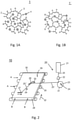
- Figure 1A 1 shows the atomic structure of an anti-reflection layer 1, which is made up of oxygen atoms 2, silicon atoms 3 and organic groups 4, 5 and 6, as is present on the substrate after the coating process.
- an anti-reflection layer 1 which is made up of oxygen atoms 2, silicon atoms 3 and organic groups 4, 5 and 6, as is present on the substrate after the coating process.
- a chemical reaction takes place, in particular oxidation or nitration, which in the illustrated case separates the organic groups 5 and 6 from the composite.
- This enlarges the cavities 7, 8, 9, which have a refractive index similar to that of air and, together with the remaining structure, result in an average refractive index in the range between 1.3 and 1.4.
- the organic groups 4, 5, 6 are released by a targeted supply of energy to the layer .
- the energy required by the method according to the invention significantly lower than with a conventional tempering process.
- the substrate itself is heated only very slightly, for example to about 45° C., so that no changes take place in the substrate itself and no cooling times are necessary. All this makes the method according to the invention more energy-efficient and therefore more environmentally friendly, more cost-effective and time-saving.
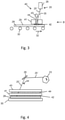
- the 2 1 shows a device for producing an anti-reflection layer with a laser unit 20, which generates a laser beam 25, and a plurality of components 22, 24, 26 that modify or deflect the laser beam.
- a substrate 28 has at least one surface that is provided with a layer 29.
- the laser unit 20 consists of a laser 21, for example a CO 2 laser, an Nd:YAG laser or a Yb:YAG laser.
- the laser 21 can work either in continuous wave mode (cw mode) or in pulsed mode.
- the emitted laser beam 25 is preferably expanded by an optical beam expander, for example a telescope, and reflected by a polygon mirror 23 .
- the reflected 25' beam hits a deflection mirror 26 which deflects the laser beam towards the layer.
- the optical beam expander 22 expands the laser beam and ensures a uniform distribution of the laser energy over the entire beam cross section, so that the laser beam or laser spot striking the layer 29 has a uniform energy distribution in this area.
- the polygon mirror 23 consists of a cylindrical base body on which flat mirror elements are attached, which butt flush against one another. When the polygon mirror 23 is rotated e.g. clockwise, as indicated by the arrow 24, the beam 25' is deflected in the direction of the arrow 33 on the mirror 26. The laser beam 25' thus travels over the mirror 26 in the direction of the arrow. This changes the angle of incidence and thus the angle of emergence of the reflected beam 25", which is thus guided line by line over the layer 29. On the layer 29, the laser spots 27 line up to form a continuous line, in the area of which the previously described chemical reaction of the layer takes place.
- the substrate 28 is preferably located on a transport device 30 which moves the substrate 28 in a transport direction 32 via rollers.
- the laser beam 25 transitions from one plane mirror segment of the polygon mirror 23 to the next plane mirror segment, the laser beam 25" is abruptly deflected from one end of the scanned line to the other end.
- the beam 25 travels in the direction of the arrow 34 over the layer 29. Combined with the transport direction 32, this results in a line-by-line scanning of the entire layer width and layer length.
- the irradiation process can be divided into two or more sub-areas, which in each case cover adjacent parts of the substrate.
- FIG. 3 now shows a device for producing the reflection-reducing layer with a post-processing unit 40, which consists of a laser unit 20, a plasma unit 41 and an excimer lamp 43.
- the substrate 28 is located, as already in 2 described, on a transport device 30, which moves the substrate in the transport direction 32.
- 3 shows the device in a side view, which corresponds to a viewing direction in the direction of arrow A in 2 is equivalent to.
- the laser beam 25" is deflected at an angle 35 by the mirror 26 onto the layer 29.
- Perpendicular irradiation as represented by the dot-dash line, still has the small disadvantage that the laser light 25" reflected from the layer 29 falls directly on the Mirror 26 is reflected and could damage the mirror 26.
- the plasma unit 41 generates a plasma 42, for example by barrier discharge, which already makes an energy input into the layer 29 in the area in which the laser beam strikes the layer 29.
- the plasma unit 41 has an opening, for example a slit, through which the laser beam 25'' strikes the layer 29 through the plasma.
- the light 44 emitted by the excimer lamp 43 also strikes the layer in this area
- the light emitted by an excimer lamp 43 has a wavelength between 120 nm and 350 nm. Thus, transitions are induced in the atomic structure of the layer and the organic groups are triggered particularly effectively.
- the post-processing device comprises a laser unit 20 and a plasma unit 41 and possibly a Excimer lamp 43. Only the performance of the individual units must be matched.
- the laser unit 20 is shown in a simplified manner by the polygon mirror 23 and the deflection mirror 26 and the beams 25' and 25".
- the laser beam 25" is, as in FIG 3 shown, is directed past the excimer lamp 43 through the aperture in the plasma unit 41 onto the layer 29 of the substrate 28.
- the laser beam 25" is guided over the layer in a direction perpendicular to the transport direction 32.
- the laser unit 41 and the excimer lamp 43 extend over this entire extent scanned by the laser beam 25", so that the laser beam 25" in the already with the Plasma 42 and the excimer light hits the substrate area 42. The supply of energy in this area is therefore sufficient to bring about the chemical reaction to the desired extent in layer 29.
- the input of energy from plasma 42 and the excimer lamp is not sufficient on its own to induce this chemical reaction to the desired extent.
- the chemical reaction is an oxidation or a nitration.
- the oxygen content or nitrogen content of the ambient air will be sufficient.
- the reaction can also be carried out in a special chamber that is purged with oxygen or nitrogen.
- FIG 5 shows a post-processing unit 40 ′, which also includes a laser unit 20 , a plasma unit 41 and an excimer lamp 43 . While the laser unit 20 and the excimer unit 43 are mounted on the side of the substrate 28 facing the surface provided with the layer 29 , the plasma unit 41 is mounted on the opposite side of the substrate 28 . However, the plasma 42 forms on the side of the substrate 28 which faces the layer 29 . With such an arrangement of the plasma unit 41, the substrate 28, which is coated on both surfaces with a layer 29, could also be post-treated on both sides by adding a second laser unit and/or a second excimer unit, with the plasma depending on the process control being one or both sides of the substrate 28 ignites.
- the plasma unit 41 can induce a plasma by electrical high voltage as in a barrier discharge device by DC voltage, by an AC voltage in the medium frequency range, by an AC voltage in the radio frequency range or by microwave radiation or with the aid of a laser.
- the plasma unit 41 can be operated at atmospheric pressure or else in a vacuum or in a special gas atmosphere.
- the plasma 42 can be restricted in its propagation by electromagnetic precautions and kept in a so-called confinement, e.g. by an electromagnetic high-frequency field.
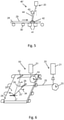
- FIG. 12 shows a device for producing the anti-reflection layer 29 with a laser unit 20 and a plasma unit 50, the plasma unit 50 comprising a laser 51.
- the plasma unit 50 comprising a laser 51.
- the laser unit 20 represented here by the laser 21
- the polygon mirror 23, the deflection mirror 26 and the laser beam 25" guided over the layer 29, the plasma is also directed onto the layer 29 by a laser system with a similar deflection device.
- the laser 51 is For example, an Nd: YAG laser that works with high energy density.
- the polygon mirror 53 used is designed for the wavelength and intensity of the laser 51.
- the rotational speed of the polygon mirror 53 is preferably coupled to the polygon mirror 23 from the laser unit 21, so that an exact same beam guidance and thus placement of the laser spot 27 and the laser beam 55 on the layer 29 is given.
- the laser beam 55 strikes a target that is in the direct vicinity of the laser beam 25" and releases ions and electrons from the target and thus generates a laser-induced plasma spot 56. This migrates line by line with the laser beam over the layer 29
- the target for plasma generation can, for example, extend over the entire width of the substrate 28, with the substrate 29 migrating under the target.
- the different laser types mentioned in a laser unit can be combined with the different types of plasma generation.
- an excimer laser for irradiation with UV light can be carried along with the laser unit, so that both the laser beam and the excimer irradiation and also the plasma generation are focused on a single point and move together line by line over the substrate .
- the devices described can be used for a one-sided post-treatment of a layer 29 as well as for a simultaneous post-treatment of layers applied on both sides of the substrate 28 .
Landscapes
- Chemical & Material Sciences (AREA)
- Materials Engineering (AREA)
- Engineering & Computer Science (AREA)
- Chemical Kinetics & Catalysis (AREA)
- General Chemical & Material Sciences (AREA)
- Geochemistry & Mineralogy (AREA)
- Life Sciences & Earth Sciences (AREA)
- Organic Chemistry (AREA)
- Physical Or Chemical Processes And Apparatus (AREA)
- Surface Treatment Of Glass (AREA)
- Chemical Vapour Deposition (AREA)
- Laser Beam Processing (AREA)
- Recrystallisation Techniques (AREA)
Description
- Die Erfindung bezieht sich auf ein Verfahren zur Herstellung auf einem Substrat einer reflexionsmindernden Schicht.
- Durch Reflexion des sichtbaren und nicht sichtbaren Spektralanteils des Sonnenlichts sinkt die Effizienz der Sonnenlichtausnutzung beispielsweise bei solaren Wärmeabsorbern oder Fotovoltaik-Modulen, die als Abdeckung eine Glasscheibe aufweisen. Gleiches gilt auch beispielsweise für Gewächshausverglasungen, die in der Regel so konzipiert sein sollten, dass bei zunehmender Lichteinstrahlung der Innenraum entsprechend erwärmt wird. Bei Solarkollektoren für die Warmwassergewinnung sowie Gewächshausverglasungen trägt das gesamte Spektrum des Sonnenlichts zur Erwärmung bei. Bei der Stromerzeugung mittels Fotovoltaik-Modulen wird auf Grund des physikalischen Grundprinzips von Solarzellen nur Strahlung bis zu einer maximalen Wellenlänge zu Strom umgesetzt. Diese Wellenlänge ist abhängig vom Typ der Solarzelle und liegt für die meisten heute gebräuchlichen Typen bei 1200 nm oder darunter.
- Beim Übergang des Lichtes von Luft mit einem Brechungsindex von nahezu n=1 zu Glas mit einem Brechungsindex etwa n=1,5 wird auf Grund des Brechungsindexunterschieds ein Teil des Lichts reflektiert. Durch eine Beschichtung der Glasoberflächen mit einer Schicht, deren Brechungsindex und Schichtdicke so gewählt ist, dass sich die beiden reflektierten Strahlen nahezu auslöschen, wird der reflektierte Lichtanteil gesenkt und gemäß dem Prinzip der Energieerhaltung der transmittierte Lichtanteil erhöht. Eine optimale Entspiegelung von Luft zu Glas ergibt sich aus den Fresnel'schen Formeln bei einem Brechungsindex von n=√1, 5=1, 22. Zusammen mit der λ/4 -Bedingung für eine destruktive Interferenz ergibt sich also für Licht im sichtbaren Spektralbereich eine Schichtdicke von ca. 50-200 nm für die optimale Entspiegelungsschicht. Für Licht mit ca. 550 nm Wellenlänge, das die größte Intensität im Sonnenspektrum darstellt, beträgt die theoretisch optimale Schichtdicke 113 nm.
- Eine reflexmindernde Schicht und ein Verfahren zur Herstellung eines transparenten Substrats mit einem Brechungsindex von n < 1,4 mit einer reflexmindernden Schicht von n < 1,32 wird in der
DE 10 2005 007 825 A1 beschrieben. Es handelt sich dabei um eine Einfachschicht, die die Elemente Silizium, Sauerstoff, Kohlenstoff und Wasserstoff enthält und im Gegensatz zu aufwendig herstellbaren und kostenintensiven Interferenzschichten, einfach und günstig herstellbar ist. Gesteuert durch die prozentuale Zusammensetzung der einzelnen Elemente bildet sich eine Gitter-Struktur aus Silizium und Sauerstoff aus, in denen durch Anlagerung von organischen Gruppen Hohlräume entstehen. Die Hohlräume entsprechen in ihrem Brechungsindex in etwa dem der Luft und senken im Mittel den Brechungsindex der Schicht ab. Um den Brechungsindex n weiter zu reduzieren muss der Anteil an organischen Gruppen gesenkt werden. - Im Stand der Technik wird der Kohlenstoff- und Wasserstoffgehalt durch eine Temperaturbehandlung der Schicht erreicht. Dabei wird die Beschichtung zusammen mit dem Substrat für einen Zeitraum von ca. 15-30 Minuten einer Temperatur von 250-800 °C ausgesetzt.
- Die Reduzierung des Kohlenstoff- und Wasserstoffgehalts durch Tempern hat den Nachteil, dass dies unter hohem Energieeinsatz erfolgt. So wird beispielsweise zur Erwärmung einer 4 mm dicken, beschichteten Floatglasscheibe eine Energie von etwa 1,5 kWh pro m2 benötigt, um diese um 600 K zu erwärmen. Bei einer zu starken Aufheizung oder auch bei einem zu schnellen Energieeintrag ergibt sich des Weiteren der Nachteil, dass die Elemente der Schicht versintern und die Poren verschwinden, wobei sich der Brechungsindex der Schicht dem des Substrats angleicht.
- Die
DE 10 2005 007 825 A1 beschreibt ein Substrat mit einer reflexionsmindernden Beschichtung, die Silicium, Sauerstoff, Kohlenstoff und Wasserstoff enthält, die jedoch nicht mit einem Laser bestrahlt ist. - Die
DE 199 18 811 A1 beschreibt ein Substrat mit einer Antireflexbeschichtung. Dabei wird eine Silicium, Kohlenstoff, Sauerstoff und Wasserstoff enthaltende kolloid-disperse Lösung auf das Substrat aufgebracht und zum Entfernen der organischen Bestandteile auf Temperaturen von mindestens 600 Grad erhitzt. Es wird nicht offenbart, dass die Schicht von einem Laser bestrahlt ist. - Es ist somit Aufgabe der vorliegenden Erfindung ein Verfahren zu schaffen, mit dem eine reflexionsminderende Beschichtung aus Silizium, Sauerstoff, Kohlenstoff und Wasserstoff auf einem transparenten Substrat zuverlässig und unter einem deutlich geringeren Energieeinsatz als durch das Tempern herstellbar ist. Das Aussintern der aufgebrachten Schicht soll dabei zuverlässig vermieden werden.
- Die Aufgabe wird durch das Verfahren gemäß Anspruch 1 gelöst.
- Die reflexionsmindernde Beschichtung auf einem Substrat, bei dem mindestens eine Schicht, die Silizium und Sauerstoff sowie Wasserstoff und/oder Kohlenstoff enthält, wird in einem Beschichtungsverfahren auf mindestens einer Seite des Substrats abgeschieden. In einem anschließenden Verfahrensschritt wird die Schicht mit einem Laser bestrahlt, wobei die Energie des Laserstrahls von der Schicht selbst und nicht vom Substrat absorbiert wird und dadurch der Wasserstoff- und Kohlenstoffgehalt der Schicht in einer chemischen Reaktion vermindert wird.
- Im erfindungsgemäßen Verfahren wird die Energie des Laserstrahls von der Schicht absorbiert. Lediglich ein geringer Anteil des Laserstrahls dringt bis zur darunterliegenden Substrat durch und gibt seine Energie an das Substrat ab. In der Schicht regt die eingekoppelte Energie eine chemische Reaktion an, bei der die organischen Gruppen aus Kohlenstoff- und Wasserstoffatomen abgetrennt werden. Durch die ausgelösten organischen Gruppen vergrößern sich die Hohlräume in der Schicht aus und senken dadurch den Brechungsindex.
- Bei der chemischen Reaktion handelt es sich um eine Oxidation, so dass Wasserstoff als H2O und Kohlenstoff als CO2 oder CO vorwiegend in der Dampfphase entweicht bzw. ausdiffundiert.
- Durch diese gezielte Energiezufuhr in die reflexionsmindernde Schicht reduziert sich der Energiebedarf auf ca. 1/10 der Energiemenge, die nach dem Stand der Technik für das Tempern benötigt wird. Das Substrat selbst wird nur leicht erwärmt, sodass sich im Substrat selbst keine Veränderungen ausbilden. Außerdem ist die Handhabung der Substrate bei Raumtemperatur einfacher zu bewerkstelligen.
- Die Schicht wird zusätzlich einem physikalischen Plasma ausgesetzt. Die Einzelleistung des Lasers und die Einzelleistung des Plasmas wird so eingestellt, dass die Einzelleistungen des Lasers und des Plasmas nicht ausreichen, um die chemische Reaktion anzuregen, aber die Summe der Einzelleistungen des Lasers und des Plasmas die chemische Reaktion in ausreichendem Maße bewirken. Damit kann die Leistung des eingesetzten Lasers niedrig gehalten werden. Eine zu starke punktuelle Energiezufuhr, die z.B. eine Ablösung der Schicht vom Substrat bewirkt kann somit minimiert werden. Andererseits wird durch das Plasma die Reaktionsbereitschaft der Schicht erhöht und in Summe eine effektivere chemische Reaktion bewirkt.
- Besonders vorteilhaft ist es, die Schicht zusätzlich mit einer Excimer-Lampe und/oder einem Excimer-Laser zu bestrahlen. Ein Excimer-Laser oder eine Excimer-Lampe emittiert Strahlung in niedrigen Ultraviolett (UV)-Bereich bei ca. 120-350 nm Wellenlänge. Die eingestrahlte Energie liegt im Bereich der molekularen Bindungsenergien, sodass Bindungen direkt aufgebrochen werden können. Dies stellt eine optimale Energieausnutzung dar und reduziert somit den Gesamtenergieverbrauch bei der Nachbehandlung der reflexionsmindernden Schicht.
- Die Vorrichtung zur Herstellung eines transparenten Substrats mit einer reflexionsmindernden Beschichtung umfasst eine Beschichtungseinheit, die mindestens eine Schicht, die Silizium und Sauerstoff sowie Kohlenstoff und/oder Wasserstoff enthält, auf mindestens einer Seite des Substrats abscheidet. Die Vorrichtung weist zudem eine Nachbearbeitungseinheit auf, die eine Lasereinheit umfasst, die einen Laserstahl über das Substrat führt. Dabei wird die Energie des Laserstrahls überwiegend von der Schicht selbst und nicht vom Substrat absorbiert. Der Laserstrahl bewirkt eine chemische Reaktion in der Schicht, die den Kohlenstoff- und/oder Wasserstoffgehalt in der Schicht vermindert.
- Vorteilhalfterweise umfasst die Lasereinheit einen CO2-Laser oder Yttrium-Aluminium-Granat(YAG)-Laser, insbesondere einen Neodym(Nd):YAG oder einen Ytterbium(Yb):YAG umfasst. Die genannten Laser sind kommerziell in unterschiedlichen Ausführungen und Leistungsstufen erhältlich.
- Da die meisten Glasarten und auch die reflexmindernde Schicht einen hohen Absorptionsgrad von Licht mit einer Wellenlänge von ca. 10 µm besitzen, eignet sich insbesondere der CO2-Laser mit seiner spezifischen Wellenlänge von 10,6 µm für die Bearbeitung der Schicht. Yb:YAG-Laser emittieren bei einer Wellenlänge von 1030 nm, Nd:YAG-Laser bei 1064 nm. Der Nd:YAG-Laser erreicht hohe Energiedichten. Der Yb:YAG-Laser erreicht durch eine höhere Dotierung eine hohe Energiedichte bei kleinen Scheibendicken. Die YAG-Laser weisen wie der CO2-Laser eine sehr gute homogene Strahlqualität auf, die eine gleichmäßige Energieeinkopplung in der Fläche ermöglicht.
- Von Vorteil ist es, wenn die Lasereinheit zur Führung des Laserstrahls eine Spiegelanordnung mit einem rotierenden Polygonspiegel umfasst. Durch die Anzahl der flächigen Einzelscheiben des Polygonspiegels sowie die Umdrehungsgeschwindigkeit kann in einfacher Weise der Laserstrahl abgelenkt und über die reflexionsmindernde Schicht geführt werden. Somit ist ein zeilenweises Bestrahlen der Schicht möglich. Insbesondere ist der Übergang von einem Zeilenende auf einen auf der gegenüberliegenden Seite der Schicht beginnenden Zeilenanfang trägheitsfrei, also ohne das Abbremsen und erneute Beschleunigen von Strahlführungskomponenten möglich.
- Ein Polygonspiegel besteht aus einem zylindrischen Grundkörper, der sich um seine Achse dreht. Auf der Zylinderoberfläche befinden sich plane Spiegel die mit ihrem Seitenrand aneinander grenzen und bündige Kanten bilden. Trifft der Laserstrahl auf einen dieser Spiegel, so wird er reflektiert und durch die Drehbewegung des Polygonspiegels zeilenartig geführt. Der Zeilenwechsel erfolgt beim Wechsel des Strahls von einem Spiegelsegment auf das nächste, der Grundkörper wird dabei gleichförmig weiterbewegt. Somit lässt sich eine schnelle und definierte Scanbewegung des Laserstrahls erreichen.
- Dabei ist von Vorteil, dass das Substrat und die Nachbearbeitungseinheit in eine Transportrichtung relativ zueinander verschiebbar sind und die Lasereinheit den Laserstrahl senkrecht zur Transportrichtung über das Substrat führt. Die Strahlablenkung durch den Polygonspiegel zusammen mit der Bewegung des Substrats relativ zur Nachbearbeitungseinheit in Transportrichtung erlaubt das Überdecken des gesamten Substrats durch den Laserstrahl bei einer kontinuierlichen Bewegung einerseits in Transportrichtung als auch einer kontinuierlichen Bewegung des Polygonspiegels für die Führung des Laserstrahls senkrecht zur Transportrichtung.
- Die Nachbearbeitungseinheit umfasst eine Plasmaeinheit, wobei die Plasmaeinheit in dem vom Laserlicht bestrahlten Bereich des Substrats ein Plasma erzeugt. Somit können der reflexmindernden Schicht kombiniert Energie durch das Laserlicht als auch durch das einwirkende Plasma zugefügt werden. Insbesondere umfasst die Plasmaeinheit ein Magneton oder eine Plasmaerzeugungseinheit basierend auf einer Barrieren-Entladung oder einen Nd:YAG-Laser zur Plasmaerzeugung. Insbesondere eine Plasmaeinheit basierend auf einer Barrieren-Entladung hat den Vorteil bei Atmosphärendruck zu arbeiten. Es muss kein Vakuum oder besondere Gasatmosphäre erzeugt werden, um das Plasma auszubilden. Ebenso sind keine Vorkehrungen zur Begrenzung des Plasmas, einem sogenannten Confinement (Eingrenzung), notwendig.
- Vorteilhafterweise erzeugt die Plasmaeinheit ein Plasma auf der Schicht in einem Bereich, der bevorzugt die gesamte Ausdehnung senkrecht zur Transportrichtung umfasst, die vom Laserstrahl bestrahlt wird. Somit kann z.B. eine ortsfeste Plasmaeinheit realisiert werden und die Anregung der Schichts chon vor der Bestrahlung mit dem Laserlicht beginnen.
- Es ist ebenso vorteilhaft, wenn die Plasmaeinheit einen Laser, insbesondere einen Nd:YAG-Laser zur Plasmaerzeugung umfasst und der Laser zur Plasmaerzeugung zusammen mit der Lasereinheit über das Substrat geführt wird. Dies reduziert weiter den Energieverbrauch und reduziert weiter die Erwärmung des Substrats.
- Sehr vorteilhaft ist es, wenn die Nachbearbeitungseinheit eine Excimer-Lampe und/oder einen Excimer-Laser zur Bestrahlung der Schicht umfasst und die Excimer-Lampe bevorzugt den vom Laserstrahl bestrahlten Bereich senkrecht zur Transportrichtung bestrahlt. Eine Excimer-Lampe kann bevorzugt den gesamten vom Laserstrahl bestrahlten Bereich senkrecht zur Transportrichtung bestrahlen, während ein Excimer-Laser mit dem Laserstrahl und/oder dem Laserstrahl zur Erzeugung eines Plasmas mitgeführt werden kann. Somit ist eine gezielte energiesparende Anregung der chemischen Reaktion zur Auslösung von Kohlenstoff und Wasserstoff aus der aufgetragenen Schicht möglich. Durch die eingekoppelte Energie der Excimer-Lampe bzw. Excimer-Lasers, die im Bereich der Bindungsenergien des Kohlenstoffs und Wasserstoffs bzw. der daraus gebildeten organischen Gruppe liegt, können sie effizient die chemischen Reaktionen stimulieren.
- Das transparente Substrat mit einer reflexionsmindernden Beschichtung, das gemäß dem Verfahren nach Anspruch 1 bis 6 hergestellt ist, umfasst eine Schicht auf mindestens einer Oberfläche des Substrats, wobei die Oberfläche eben und/oder gekrümmt geformt ist. Da zur Senkung des Wasserstoff und Kohlenstoffgehalts an der reflexionsmindernden Schicht wenig Energie dem Substrat zugeführt wird sind keinerlei Änderungen der Oberflächenform zu erwarten, sodass beliebige Oberflächenformationen mit reflexionsmindernder Beschichtung herstellbar sind.
- Ausführungsbeispiele des erfindungsgemäßen Verfahren sind in derZeichnung beispielhaft dargestellt und werden anhand der nachfolgenden Beschreibung näher erläutert. Es zeigen:
- Fig. 1A,B
- eine atomare Gitter-Struktur der reflexionsmindernden Schicht vor bzw. nach der Bestrahlung mit einem Laser in schematischer Darstellung;
- Fig. 2
- ein erstes Ausführungsbeispiel einer Vorrichtung zur Herstellung einer reflexionsmindernden Schicht mit einer Lasereinheit in perspektivischer Ansicht;
- Fig. 3
- ein zweites Ausführungsbeispiel einer Vorrichtung in Seitenansicht;
- Fig. 4
- das zweite Ausführungsbeispiel aus
Fig. 3 in Frontansicht; - Fig. 5
- ein drittes Ausführungsbeispiel einer Vorrichtung in Seitenansicht und
- Fig. 6
- ein viertes Ausführungsbeispiel einer Vorrichtung mit laserinduziertem Plasma in perspektivischer Ansicht.
- Einander entsprechende Teile sind in allen Figuren mit den gleichen Bezugszeichen versehen.
-
Fig. 1A zeigt die atomare Struktur einer reflexmindernden Schicht 1, die aus Sauerstoffatomen 2, Siliziumatomen 3 und organischen Gruppen 4, 5 und 6 aufgebaut ist, wie sie nach dem Beschichtungsverfahren auf dem Substrat vorliegt. Durch die Zuführung von Energie durch einen Laserstrahl findet eine chemische Reaktion, insbesondere Oxidation oder Nitrierung statt, die organische Gruppen im dargestellten Fall die organischen Gruppen 5 und 6 aus dem Verbund löst. Dadurch vergrößern sich die Hohlräume 7, 8, 9 die einen Brechungsindex ähnlich dem der Luft aufweisen und zusammen mit der verbleibenden Struktur einen mittleren Brechungsindex ergeben, der im Bereich zwischen 1,3 und 1,4 liegt. - Im Gegensatz zu einem Temperverfahren, in dem die abgeschiedene Schicht zusammen mit dem gesamten Substrat auf eine Temperatur von bis zu 600°C erhitzt wird, erfolgt bei dem erfindungsgemäßen Verfahren eine Auslösung der organischen Gruppen 4, 5, 6 durch eine gezielte Energiezufuhr in die Schicht. Somit ist der Energiebedarf durch das erfindungsgemäße Verfahren signifikant geringer als bei einem herkömmlichen Temperverfahren. Weiterhin wird das Substrat selbst nur sehr gering erhitzt, z.B. auf etwa 45°C, sodass keine Veränderungen im Substrat selbst stattfinden und keine Abkühlzeiten notwendig sind. Dies alles gestaltet das erfindungsgemäße Verfahren energiesparender und damit umweltverträglicher, kostengünstiger und zeitsparend.
- Nachfolgend werden unterschiedliche Ausführungsbeispiele einer Vorrichtung zur Herstellung einer reflexionsmindernden Schicht beschrieben, die in den
Figuren 2 bis 6 dargestellt sind. -
Fig. 2 zeigt eine Vorrichtung zur Herstellung einer reflexionsmindernden Schicht mit einer Lasereinheit 20, die einen Laserstrahl 25 erzeugt, und mehreren Laserstrahl modifizierenden bzw. ablenkenden Komponenten 22, 24, 26. Ein Substrat 28 weist mindestens eine Oberfläche auf, die mit einer Schicht 29 versehen ist. Die Lasereinheit 20 besteht aus einem Laser 21, z.B. eine CO2-Laser, einem Nd:YAG-Laser oder einem Yb:YAG-Laser. Der Laser 21 kann entweder im Dauerstrichbetrieb (cw-Betrieb) oder im gepulsten Betrieb arbeiten. Der emittierte Laserstrahl 25 wird bevorzugt durch einen optischen Strahlaufweiter, beispielsweise ein Teleskop, aufgeweitet und von einem Polygonspiegel 23 reflektiert. Der reflektierte 25' Strahl trifft auf einen Ablenkspiegel 26, der den Laserstrahl zur Schicht hin ablenkt. - Der optische Strahlaufweiter 22 weitet den Laserstrahl auf und sorgt für eine gleichmäßige Verteilung der Laserenergie über den gesamten Strahlquerschnitt, sodass der auf der Schicht 29 treffende Laserstrahl bzw. Laserspot eine gleichmäßige Energieverteilung in diesem Bereich aufweist. Der Polygonspiegel 23 besteht aus einem zylindrischen Grundkörper, auf dem ebene Spiegelelemente angebracht sind, die bündig aneinander stoßen. Bei Drehung des Polygonspiegels 23 z.B. im Uhrzeigersinn, wie durch den Pfeil 24 angedeutet, wird der Strahl 25' in Pfeilrichtung 33 auf dem Spiegel 26 abgelenkt. Der Laserstrahl 25' wandert also über den Spiegel 26 in Pfeilrichtung. Dadurch ändert sich der Einfalls- und damit in gleicher Weise der Ausfallswinkel des reflektierten Strahls 25", der somit zeilenweise über die Schicht 29 geführt wird. Auf der Schicht 29 reihen sich die Laserspots 27 zu einer durchgängigen Linie aneinander, in deren Bereich die vorher beschriebene chemische Reaktion der Schicht stattfindet.
- Das Substrat 28 befindet sich vorzugsweise auf einer Transportvorrichtung 30, die über Rollen das Substrat 28 in eine Transportrichtung 32 bewegt. Beim Übergang des Laserstrahls 25 von einem planen Spiegelsegment des Polygonspiegels 23 zum nächsten planen Spiegelsegment wird der Laserstrahl 25" vom einen Ende der gescannten Zeile zum anderen Ende hin abrupt abgelenkt. Solange der Laserstrahl 25 über ein Spiegelsegment wandert, wandert der Strahl 25" in Pfeilrichtung 34 über die Schicht 29. Kombiniert mit der Transportrichtung 32 ergibt sich somit ein zeilenweises Abscannen der gesamten Schichtbreite und Schichtlänge. Bei sehr breiten Substraten, kann der Bestrahlungsvorgang in zwei oder mehrere Teilbereiche, die jeweils aneinander angrenzende Teile das Substrat überdecken, unterteilt werden.
-
Fig. 3 zeigt nun eine Vorrichtung zur Herstellung der reflexionsmindernden Schicht mit einer Nachbearbeitungseinheit 40, die aus einer Lasereinheit 20, einer Plasmaeinheit 41 sowie einer Excimer-Lampe 43 steht. Das Substrat 28 befindet sich dabei, wie bereits inFig. 2 beschrieben, auf einer Transportvorrichtung 30, die das Substrat in Transportrichtung 32 bewegt.Fig. 3 zeigt dabei die Vorrichtung in Seitenansicht, was einer Blickrichtung in Pfeilrichtung A inFig. 2 entspricht. - In diesem Ausführungsbeispiel wird der Laserstrahl 25" unter einem Winkel 35 vom Spiegel 26 auf die Schicht 29 abgelenkt. Eine senkrechte Einstrahlung, wie durch die strichpunktierte Linie dargestellt, hat noch den kleinen Nachteil, dass von der Schicht 29 reflektiertes Laserlicht 25" direkt auf den Spiegel 26 zurückgeworfen wird und dabei den Spiegel 26 beschädigen könnte.
- Die Plasmaeinheit 41 erzeugt beispielsweise durch Barrieren-Entladung ein Plasma 42, das im Bereich, in dem der Laserstrahl auf die Schicht 29 trifft, bereits einen Energieeintrag in die Schicht 29 leistet. Die Plasmaeinheit 41 weist eine Öffnung, z.B. einen Schlitz, auf, durch den der Laserstrahl 25" durch das Plasma hindurch auf die Schicht 29 trifft. In diesem Bereich trifft auch das von der Excimer-Lampe 43 emittierte Licht 44 auf die Schicht. Das von einer Excimer-Lampe 43 emittierte Licht hat eine Wellenlänge zwischen 120 nm und 350 nm. Somit werden Übergänge in der atomaren Struktur der Schicht induziert und die organischen Gruppen werden besonders effektiv ausgelöst. Die Nachbearbeitungsvorrichtung umfasst eine Lasereinheit 20 und eine Plasmaeinheit 41 und ggf. eine Excimer-Lampe 43. Lediglich die Leistungen der einzelnen Einheiten müssen aufeinander abgestimmt sein.
-
Fig. 4 zeigt die Vorrichtung ausFig. 3 in Blickrichtung B inFig. 2 . Dabei ist die Lasereinheit 20 durch den Polygonspiegel 23 sowie dem Ablenkspiegel 26 und die Strahlen 25' und 25" vereinfacht dargestellt. Der Laserstrahl 25" wird, wie inFig. 3 gezeigt, an der Excimer-Lampe 43 vorbei durch die Öffnung in der Plasmaeinheit 41 hindurch auf die Schicht 29 des Substrats 28 gelenkt. Wie inFig. 2 beschrieben, wird der Laserstrahl 25" in eine Richtung senkrecht zur Transportrichtung 32 über die Schicht geführt. Die Lasereinheit 41 sowie die Excimer-Lampe 43 erstrecken sich über diese gesamte vom Laserstrahl 25" abgescannte Ausdehnung, sodass der Laserstrahl 25" in die bereits mit dem Plasma 42 und dem Excimer-Licht behandelte Substratbereich trifft. Somit ist in diesem Bereich die Energiezufuhr ausreichend, um die chemische Reaktion in der Schicht 29 im gewünschten Maße zu bewirken. Der Energieeintrag des Plasmas 42 sowie der Excimer-Lampe reichen für sich noch nicht aus um diese chemische Reaktion im gewünschten Maße zu induzieren. Bei der chemischen Reaktion handelt es sich um eine Oxidation oder eine Nitrierung. Dabei wird in der Regel der Sauerstoffgehalt bzw. Stickstoffgehalt der Umgebungsluft ausreichen. Eventuell kann die Reaktion aber auch in einer speziellen Kammer durchgeführt werden, die mit Sauerstoff bzw. Stickstoff gespült wird. -
Fig. 5 zeigt eine Nachbearbeitungseinheit 40' die ebenfalls eine Lasereinheit 20, eine Plasmaeinheit 41 sowie eine Excimer-Lampe 43 umfasst. Während die Lasereinheit 20 sowie die Excimer-Einheit 43 auf der mit der Schicht 29 versehenen Oberfläche des Substrats 28 zugewandten Seite angebracht sind, ist die Plasmaeinheit 41 auf der gegenüberliegenden Seite des Substrats 28 angebracht. Das Plasma 42 bildet sich jedoch auf der Seite des Substrats 28, das der Schicht 29 zugewandt ist. Mit einer solchen Anordnung der Plasmaeinheit 41 könnte auch eine beidseitige Nachbehandlung des Substrats 28, das auf beiden Oberflächen mit einer Schicht 29 beschichtet ist durch hinzufügen einer zweiten Lasereinheit und/oder einer zweiten Excimer-Einheit durchgeführt werden, wobei das Plasma je nach Prozessführung auf jeweils einer oder beiden Seiten des Substrats 28 zündet. - Die Plasmaeinheit 41 kann ein Plasma durch elektrische Hochspannung wie bei einer Barrieren-Entladungsvorrichtung durch Gleichspannung, durch eine Wechselspannung im Mittelfrequenzbereich, durch eine Wechselspannung im Radiofrequenzbereich oder auch durch eine Mikrowellenstrahlung oder mit Hilfe eines Lasers induzieren. Die Plasmaeinheit 41 kann bei Atmosphärendruck oder aber auch in einem Vakuum oder in einer besonderen Gasatmosphäre betrieben werden. Ebenso kann das Plasma 42 durch elektromagnetische Vorkehrungen in seiner Ausbreitung eingeschränkt und in einem sogenannten Confinement , z.B. durch ein elektromagnetische Hochfrequenz-Feld, gehalten werden.
-
Fig. 6 stellt eine Vorrichtung zur Herstellung der reflexionsmindernden Schicht 29 mit einer Lasereinheit 20 sowie einer Plasmaeinheit 50 dar, wobei die Plasmaeinheit 50 einen Laser 51 umfasst. Neben der Lasereinheit 20, hier dargestellt durch den Laser 21, den Polygonspiegel 23, den Ablenkspiegel 26 sowie den über die Schicht 29 geführten Laserstrahl 25", wird das Plasma ebenso durch ein Lasersystem mit ähnlicher Ablenkvorrichtung auf die Schicht 29 gerichtet. Der Laser 51 ist beispielweise ein Nd:YAG-Laser, der mit hoher Energiedichte arbeitet. Der verwendete Polygonspiegel 53 ist dabei auf die Wellenlänge und Intensität des Lasers 51 ausgelegt. Die Drehgeschwindigkeit des Polygonspiegels 53 ist mit dem Polygonspiegel 23 aus der Lasereinheit 21 vorzugsweise gekoppelt, sodass eine exakt gleiche Strahlenführung und somit Platzierung des Laserspots 27 sowie des Laserstrahls 55 auf der Schicht 29 gegeben ist. - Der Laserstrahl 55 trifft auf ein Target, das sich in direkter Nachbarschaft des Laserstrahls 25" befindet und löst dabei Ionen und Elektronen aus dem Target aus und erzeugt so einen Laser-induzierten Plasmaspot 56. Dieser wandert mit dem Laserstrahl zeilenwiese über die Schicht 29. Das Target für die Plasmaerzeugung kann sich beispielsweise über die gesamte Breite des Substrats 28 erstrecken, wobei das Substrat 29 unter dem Target hinweg wandert.
- Alle beschriebenen und/oder gezeichneten Merkmale können im Rahmen der Erfindung vorteilhaft miteinander kombiniert werden. Insbesondere können die unterschiedlichen genannten Lasertypen einer Lasereinheit mit den unterschiedlichen Arten der Plasmaerzeugung kombiniert werden. Ebenso kann statt einer Excimer-Lampe ein Excimer-Laser zur Bestrahlung mit UV-Licht mit der Lasereinheit mitgeführt werden, sodass sowohl der Laserstrahl als auch die Excimer-Bestrahlung und auch die Plasmaerzeugung auf einen einzigen Punkt fokussiert sind und gemeinsam zeilenweise über das Substrat wandern. Die beschriebenen Vorrichtungen können für eine einseitige Nachbehandlung einer Schicht 29 als auch zu einer gleichzeitigen Nachbehandlung von beidseitig des Substrats 28 aufgetragen Schichten verwendet werden.
Claims (6)
- Verfahren zur Herstellung einer reflexionsmindernden Beschichtung auf einem Substrat (28), bei dem mindestens eine Schicht (29), die Silizium und Sauerstoff und Kohlenstoff und Wasserstoff enthält, in einem Beschichtungsverfahren auf mindestens einer Seite des Substrats (28) abgeschieden wird,
dadurch gekennzeichnet,dass in einem anschließenden Verfahrensschrittdie Schicht (29) von einem Laser (21) bestrahlt wird und dadurch der Wasserstoff-Gehalt und KohlenstoffGehalt der Schicht (29) in einer chemischen Reaktion vermindert wird, wobei die chemische Reaktion eine Oxidation und/oder Nitrierung ist,dass auf den vom Laserlicht bestrahlten Bereich der Schicht (29) zusätzlich ein physikalisches Plasma (42) einwirkt, unddass eine Einzel-Leistungsdichte des Lasers (21) und eine Einzelleistung des Plasmas (42) so eingestellt sind, dass die Einzel-Leistungsdichte des Lasers (21) und die Einzel-Leistungsdichte des Plasmas (42) nicht ausreichen, die chemische Reaktion anzuregen, die Summe derEinzel-Leistungsdichten des Lasers (21) und des Plasmas (42) aber die chemische Reaktion in ausreichendem Maße bewirkt. - Verfahren nach Anspruch 1,
dadurch gekennzeichnet,
dass die Einstrahlung des Laserstrahls (25) durch einen CO2-Laser, einen Nd(Neodym):YAG-Laser oder einen Yb(Ytterbium):YAG-Laser erfolgt. - Verfahren nach Anspruch 1,
dadurch gekennzeichnet,
dass das Plasma (42) mit Hilfe einer elektrischen Hochspannung, einer Gleichspannung, einer Wechselspannung im Mittelfrequenzbereich, einer Wechselspannung im Radiofrequenzbereich, einer Mikrowellenstrahlung oder mit Hilfe eines Lasers (51) induziert wird, insbesondere dass zur Erzeugung des Plasmas (42) eine Barrieren-Entladung, eine Magnetron oder ein Nd:YAG Laser verwendet wird. - Verfahren nach einem der Ansprüche 1 bis 3, dadurch gekennzeichnet,
dass das Plasma (42) durch ein Hochfrequenz-Feld räumlich begrenzt wird. - Verfahren nach einem der Ansprüche 1 bis 4,
dadurch gekennzeichnet,
dass die Schicht (29) zusätzlich mit einer Excimer-Lampe (43) bestrahlt wird. - Verfahren nach einem der Ansprüche 1 bis 5,
dadurch gekennzeichnet,
dass die Schicht (29) vor der Behandlung mit Laserlicht (25) eine Schichtdicke zwischen 120nm und 170nm, bevorzugt eine Schichtdicke zwischen 130nm und 160nm und besonders bevorzugt etwa 150nm aufweist, und die Schicht (29) nach der Behandlung mit Laserlicht (25) und/oder einem Plasma (42) und/oderder Excimer-Lampe (43) eine Schichtdicke zwischen 80nm und 110nm, bevorzugt eine Schichtdicke von etwa 100nm aufweist.
Applications Claiming Priority (1)
| Application Number | Priority Date | Filing Date | Title |
|---|---|---|---|
| DE102010054858.8A DE102010054858C5 (de) | 2010-12-17 | 2010-12-17 | Verfahren und Vorrichtung zur Herstellung einer reflexionsmindernden Beschichtung |
Publications (4)
| Publication Number | Publication Date |
|---|---|
| EP2465832A2 EP2465832A2 (de) | 2012-06-20 |
| EP2465832A3 EP2465832A3 (de) | 2012-08-08 |
| EP2465832B1 EP2465832B1 (de) | 2018-02-21 |
| EP2465832B2 true EP2465832B2 (de) | 2022-03-09 |
Family
ID=45463241
Family Applications (1)
| Application Number | Title | Priority Date | Filing Date |
|---|---|---|---|
| EP11193150.7A Active EP2465832B2 (de) | 2010-12-17 | 2011-12-13 | Verfahren zur Herstellung einer reflexionsmindernden Beschichtung |
Country Status (2)
| Country | Link |
|---|---|
| EP (1) | EP2465832B2 (de) |
| DE (1) | DE102010054858C5 (de) |
Families Citing this family (1)
| Publication number | Priority date | Publication date | Assignee | Title |
|---|---|---|---|---|
| DE102015113141A1 (de) | 2014-12-15 | 2016-06-16 | Mauser-Werke Oberndorf Maschinenbau Gmbh | Verfahren zur Bearbeitung einer Werkstückoberfläche und Werkstück |
Citations (10)
| Publication number | Priority date | Publication date | Assignee | Title |
|---|---|---|---|---|
| EP0142039A2 (de) † | 1983-11-09 | 1985-05-22 | Landert-Motoren-AG | Vorrichtung zum automatischen Öffnen und Schliessen von Schiebetüren |
| US6177131B1 (en) † | 1996-10-14 | 2001-01-23 | Fraunhofer-Gesellschaft zur Förderung der angewandten Forschung e.V. | Method of making an anti-reflection coating |
| US20040028809A1 (en) † | 2000-10-19 | 2004-02-12 | Bein Thomas W. | Porous layers and method for production thereof by means of spin-coating |
| US20040185679A1 (en) † | 2003-03-21 | 2004-09-23 | Ott Andrew W. | Forming a dielectric layer using porogens |
| US20050237895A1 (en) † | 2004-04-23 | 2005-10-27 | Semiconductor Energy Laboratory Co., Ltd. | Laser irradiation apparatus and method for manufacturing semiconductor device |
| EP1670049A1 (de) † | 2003-09-17 | 2006-06-14 | Tokyo Electron Limited | Herstellung eines isolationsfilms mit niedriger dielektrizitätskonstante |
| WO2008096089A2 (fr) † | 2007-01-05 | 2008-08-14 | Saint-Gobain Glass France | Procede de depot de couche mince et produit obtenu |
| US20090220774A1 (en) † | 2008-03-03 | 2009-09-03 | Keio University | Anti-reflection coating and its production method |
| WO2010139908A1 (fr) † | 2009-06-05 | 2010-12-09 | Saint-Gobain Glass France | Procede de depot de couche mince et produit obtenu |
| WO2010142126A1 (zh) † | 2009-06-10 | 2010-12-16 | 中兴通讯股份有限公司 | 一种射频识别系统及其防碰撞的标签清点结束方法 |
Family Cites Families (13)
| Publication number | Priority date | Publication date | Assignee | Title |
|---|---|---|---|---|
| DE4216508A1 (de) * | 1992-05-19 | 1993-11-25 | Ortwin Dr Brandt | Feststoffanalysengerät (Vorrichtung und Verfahren) |
| DE19918811A1 (de) * | 1999-04-26 | 2000-11-02 | Fraunhofer Ges Forschung | Vorgespanntes, mit einer wischfesten, porösen SiO¶2¶-Antireflex-Schicht versehenes Sicherheitsglas u. Verfahren z. d. Herstellung |
| EP1420439B1 (de) * | 2002-11-14 | 2012-08-29 | Air Products And Chemicals, Inc. | Nicht-thermischer Prozess für die Herstellung poröser Filme mit niedriger Dielektrizitätskonstante |
| US7404990B2 (en) | 2002-11-14 | 2008-07-29 | Air Products And Chemicals, Inc. | Non-thermal process for forming porous low dielectric constant films |
| US8137764B2 (en) | 2003-05-29 | 2012-03-20 | Air Products And Chemicals, Inc. | Mechanical enhancer additives for low dielectric films |
| DE102005007825B4 (de) | 2005-01-10 | 2015-09-17 | Interpane Entwicklungs-Und Beratungsgesellschaft Mbh | Verfahren zur Herstellung einer reflexionsmindernden Beschichtung, reflexionsmindernde Schicht auf einem transparenten Substrat sowie Verwendung einer derartigen Schicht |
| DE102005020168A1 (de) * | 2005-04-28 | 2006-11-02 | Schott Ag | Entspiegelungsschicht und Verfahren zu deren Aufbringung |
| DE102005038901B4 (de) * | 2005-08-17 | 2019-05-23 | Interpane Entwicklungs- Und Beratungsgesellschaft Mbh & Co Kg | Verglasungselement |
| US9138913B2 (en) * | 2005-09-08 | 2015-09-22 | Imra America, Inc. | Transparent material processing with an ultrashort pulse laser |
| EP2065120B1 (de) * | 2006-09-19 | 2015-07-01 | Hamamatsu Photonics K.K. | Laserbearbeitungsverfahren |
| RU2365648C1 (ru) * | 2008-02-26 | 2009-08-27 | Федеральное Государственное Унитарное Предприятие "Центральный Научно-Исследовательский Институт Конструкционных Материалов "Прометей" (Фгуп "Цнии Км "Прометей ") | Способ очистки кремний-кальцийсодержащего концентрата от примесей |
| DE102009033417C5 (de) * | 2009-04-09 | 2022-10-06 | Interpane Entwicklungs-Und Beratungsgesellschaft Mbh | Verfahren und Anlage zur Herstellung eines beschichteten Gegenstands mittels Tempern |
| FR2946639B1 (fr) * | 2009-06-12 | 2011-07-15 | Saint Gobain | Procede de depot de couche mince et produit obtenu. |
-
2010
- 2010-12-17 DE DE102010054858.8A patent/DE102010054858C5/de active Active
-
2011
- 2011-12-13 EP EP11193150.7A patent/EP2465832B2/de active Active
Patent Citations (10)
| Publication number | Priority date | Publication date | Assignee | Title |
|---|---|---|---|---|
| EP0142039A2 (de) † | 1983-11-09 | 1985-05-22 | Landert-Motoren-AG | Vorrichtung zum automatischen Öffnen und Schliessen von Schiebetüren |
| US6177131B1 (en) † | 1996-10-14 | 2001-01-23 | Fraunhofer-Gesellschaft zur Förderung der angewandten Forschung e.V. | Method of making an anti-reflection coating |
| US20040028809A1 (en) † | 2000-10-19 | 2004-02-12 | Bein Thomas W. | Porous layers and method for production thereof by means of spin-coating |
| US20040185679A1 (en) † | 2003-03-21 | 2004-09-23 | Ott Andrew W. | Forming a dielectric layer using porogens |
| EP1670049A1 (de) † | 2003-09-17 | 2006-06-14 | Tokyo Electron Limited | Herstellung eines isolationsfilms mit niedriger dielektrizitätskonstante |
| US20050237895A1 (en) † | 2004-04-23 | 2005-10-27 | Semiconductor Energy Laboratory Co., Ltd. | Laser irradiation apparatus and method for manufacturing semiconductor device |
| WO2008096089A2 (fr) † | 2007-01-05 | 2008-08-14 | Saint-Gobain Glass France | Procede de depot de couche mince et produit obtenu |
| US20090220774A1 (en) † | 2008-03-03 | 2009-09-03 | Keio University | Anti-reflection coating and its production method |
| WO2010139908A1 (fr) † | 2009-06-05 | 2010-12-09 | Saint-Gobain Glass France | Procede de depot de couche mince et produit obtenu |
| WO2010142126A1 (zh) † | 2009-06-10 | 2010-12-16 | 中兴通讯股份有限公司 | 一种射频识别系统及其防碰撞的标签清点结束方法 |
Non-Patent Citations (3)
| Title |
|---|
| "Permittivité" † |
| CONRADS ET AL.: "Plasma generation and plasma sources", PLASMA SOURCES SCI. TECHNOL., vol. 9, no. 4, 1 November 2000 (2000-11-01), pages 441 - 454 † |
| JANSON ET AL: "Preparation of thin silica films with controlled thickness and tunable refractive index" † |
Also Published As
| Publication number | Publication date |
|---|---|
| DE102010054858A1 (de) | 2012-06-21 |
| EP2465832A2 (de) | 2012-06-20 |
| DE102010054858C5 (de) | 2024-04-11 |
| EP2465832B1 (de) | 2018-02-21 |
| DE102010054858B4 (de) | 2019-05-23 |
| EP2465832A3 (de) | 2012-08-08 |
Similar Documents
| Publication | Publication Date | Title |
|---|---|---|
| DE102009033417B4 (de) | Verfahren und Anlage zur Herstellung eines beschichteten Gegenstands mittels Tempern | |
| RU2685616C1 (ru) | Способ создания линейных канавок и устройство для образования линейных канавок | |
| DE69928488T2 (de) | Laserbearbeitung von einer Dünnschicht | |
| DE3826046C2 (de) | ||
| EP1166358B1 (de) | Verfahren zum abtragen von dünnen schichten auf einem trägermaterial | |
| DE60112053T2 (de) | Verfahren zum lokalen entfernen einer beschichtung auf einem transluzenten oder transparenten substrat | |
| EP2529406B1 (de) | Verfahren zur herstellung eines beschichteten gegenstands mit texturätzen | |
| DE202009018926U1 (de) | Material umfassend ein Substrat und wenigstens eine Dünnschicht auf Basis von Titanoxid | |
| DE102010055404A1 (de) | Verfahren zum Herstellen von Nanopartikellösungen basierend auf gepulster Laserablation zur Herstellung von Dünnschicht-Solarzellen | |
| DE19824639A1 (de) | Glassubstrat | |
| EP2744763A1 (de) | Verfahren und vorrichtung zur herstellung eines niedrigemittierenden schichtsystems | |
| DE102011111998A1 (de) | Verfahren zur Strukturierung einer Oberfläche | |
| EP4113180B1 (de) | Verfahren zum bilden von freistehenden mikrostrukturen an einem diamant-kristall | |
| EP2520394B1 (de) | Vorrichtung und Verfahren zum Randentschichten und Kerben beschichteter Substrate mit zwei von der gleichen Seite auf das beschichtete transparente Substrat einwirkenden Laserquellen | |
| EP2465832B2 (de) | Verfahren zur Herstellung einer reflexionsmindernden Beschichtung | |
| WO2012140253A1 (de) | Verfahren und vorrichtung zur thermischen behandlung von substraten | |
| DE102009059193B4 (de) | Verfahren zur Dotierung von Halbleitermaterialien | |
| DE4119910C1 (en) | Mfr. or treatment of material layers of high temp. fuel cell - involves irradiation with laser, IR or electron beam or microwaves in selected areas | |
| DE102011102270A1 (de) | Verfahren und Vorrichtung zur Ablation von Schichten von Halbleitersubstraten, sowie zur Nachbehandlung | |
| EP1927139B1 (de) | Verfahren zur bearbeitung von solarzellen mit lasergeschriebenen grabenkontakten | |
| WO2008128781A1 (de) | Verfahren zur umstrukturierung von halbleiterschichten | |
| DE102013107799B4 (de) | Verfahren zur Herstellung einer strukturierten, transparenten und leitfähigen Oxidschicht und eines Dünnschichtbauelements | |
| DE102013113108B4 (de) | Solarzellenherstellungsverfahren | |
| KR100740117B1 (ko) | 평면 표시소자용 전자 방출원의 제조 방법과 이 전자방출원의 활성화 장치 | |
| DE102015104649A1 (de) | Solarzellenherstellungsverfahren |
Legal Events
| Date | Code | Title | Description |
|---|---|---|---|
| PUAI | Public reference made under article 153(3) epc to a published international application that has entered the european phase |
Free format text: ORIGINAL CODE: 0009012 |
|
| AK | Designated contracting states |
Kind code of ref document: A2 Designated state(s): AL AT BE BG CH CY CZ DE DK EE ES FI FR GB GR HR HU IE IS IT LI LT LU LV MC MK MT NL NO PL PT RO RS SE SI SK SM TR |
|
| AX | Request for extension of the european patent |
Extension state: BA ME |
|
| PUAL | Search report despatched |
Free format text: ORIGINAL CODE: 0009013 |
|
| AK | Designated contracting states |
Kind code of ref document: A3 Designated state(s): AL AT BE BG CH CY CZ DE DK EE ES FI FR GB GR HR HU IE IS IT LI LT LU LV MC MK MT NL NO PL PT RO RS SE SI SK SM TR |
|
| AX | Request for extension of the european patent |
Extension state: BA ME |
|
| RIC1 | Information provided on ipc code assigned before grant |
Ipc: C23C 16/56 20060101ALI20120703BHEP Ipc: C03C 17/245 20060101ALI20120703BHEP Ipc: C03C 17/22 20060101AFI20120703BHEP |
|
| 17P | Request for examination filed |
Effective date: 20120712 |
|
| STAA | Information on the status of an ep patent application or granted ep patent |
Free format text: STATUS: EXAMINATION IS IN PROGRESS |
|
| 17Q | First examination report despatched |
Effective date: 20170718 |
|
| REG | Reference to a national code |
Ref country code: DE Ref legal event code: R079 Ref document number: 502011013757 Country of ref document: DE Free format text: PREVIOUS MAIN CLASS: C03C0017220000 Ipc: C03C0017000000 |
|
| GRAP | Despatch of communication of intention to grant a patent |
Free format text: ORIGINAL CODE: EPIDOSNIGR1 |
|
| STAA | Information on the status of an ep patent application or granted ep patent |
Free format text: STATUS: GRANT OF PATENT IS INTENDED |
|
| RIC1 | Information provided on ipc code assigned before grant |
Ipc: C03C 17/23 20060101ALI20171009BHEP Ipc: C03C 17/00 20060101AFI20171009BHEP |
|
| INTG | Intention to grant announced |
Effective date: 20171102 |
|
| GRAS | Grant fee paid |
Free format text: ORIGINAL CODE: EPIDOSNIGR3 |
|
| GRAA | (expected) grant |
Free format text: ORIGINAL CODE: 0009210 |
|
| STAA | Information on the status of an ep patent application or granted ep patent |
Free format text: STATUS: THE PATENT HAS BEEN GRANTED |
|
| AK | Designated contracting states |
Kind code of ref document: B1 Designated state(s): AL AT BE BG CH CY CZ DE DK EE ES FI FR GB GR HR HU IE IS IT LI LT LU LV MC MK MT NL NO PL PT RO RS SE SI SK SM TR |
|
| REG | Reference to a national code |
Ref country code: GB Ref legal event code: FG4D Free format text: NOT ENGLISH |
|
| REG | Reference to a national code |
Ref country code: CH Ref legal event code: EP |
|
| REG | Reference to a national code |
Ref country code: DE Ref legal event code: R096 Ref document number: 502011013757 Country of ref document: DE Ref country code: AT Ref legal event code: REF Ref document number: 971507 Country of ref document: AT Kind code of ref document: T Effective date: 20180315 |
|
| REG | Reference to a national code |
Ref country code: IE Ref legal event code: FG4D Free format text: LANGUAGE OF EP DOCUMENT: GERMAN |
|
| REG | Reference to a national code |
Ref country code: NL Ref legal event code: MP Effective date: 20180221 |
|
| REG | Reference to a national code |
Ref country code: LT Ref legal event code: MG4D |
|
| PG25 | Lapsed in a contracting state [announced via postgrant information from national office to epo] |
Ref country code: ES Free format text: LAPSE BECAUSE OF FAILURE TO SUBMIT A TRANSLATION OF THE DESCRIPTION OR TO PAY THE FEE WITHIN THE PRESCRIBED TIME-LIMIT Effective date: 20180221 Ref country code: NO Free format text: LAPSE BECAUSE OF FAILURE TO SUBMIT A TRANSLATION OF THE DESCRIPTION OR TO PAY THE FEE WITHIN THE PRESCRIBED TIME-LIMIT Effective date: 20180521 Ref country code: HR Free format text: LAPSE BECAUSE OF FAILURE TO SUBMIT A TRANSLATION OF THE DESCRIPTION OR TO PAY THE FEE WITHIN THE PRESCRIBED TIME-LIMIT Effective date: 20180221 Ref country code: FI Free format text: LAPSE BECAUSE OF FAILURE TO SUBMIT A TRANSLATION OF THE DESCRIPTION OR TO PAY THE FEE WITHIN THE PRESCRIBED TIME-LIMIT Effective date: 20180221 Ref country code: LT Free format text: LAPSE BECAUSE OF FAILURE TO SUBMIT A TRANSLATION OF THE DESCRIPTION OR TO PAY THE FEE WITHIN THE PRESCRIBED TIME-LIMIT Effective date: 20180221 Ref country code: NL Free format text: LAPSE BECAUSE OF FAILURE TO SUBMIT A TRANSLATION OF THE DESCRIPTION OR TO PAY THE FEE WITHIN THE PRESCRIBED TIME-LIMIT Effective date: 20180221 Ref country code: CY Free format text: LAPSE BECAUSE OF FAILURE TO SUBMIT A TRANSLATION OF THE DESCRIPTION OR TO PAY THE FEE WITHIN THE PRESCRIBED TIME-LIMIT Effective date: 20180221 |
|
| PG25 | Lapsed in a contracting state [announced via postgrant information from national office to epo] |
Ref country code: SE Free format text: LAPSE BECAUSE OF FAILURE TO SUBMIT A TRANSLATION OF THE DESCRIPTION OR TO PAY THE FEE WITHIN THE PRESCRIBED TIME-LIMIT Effective date: 20180221 Ref country code: LV Free format text: LAPSE BECAUSE OF FAILURE TO SUBMIT A TRANSLATION OF THE DESCRIPTION OR TO PAY THE FEE WITHIN THE PRESCRIBED TIME-LIMIT Effective date: 20180221 Ref country code: GR Free format text: LAPSE BECAUSE OF FAILURE TO SUBMIT A TRANSLATION OF THE DESCRIPTION OR TO PAY THE FEE WITHIN THE PRESCRIBED TIME-LIMIT Effective date: 20180522 Ref country code: RS Free format text: LAPSE BECAUSE OF FAILURE TO SUBMIT A TRANSLATION OF THE DESCRIPTION OR TO PAY THE FEE WITHIN THE PRESCRIBED TIME-LIMIT Effective date: 20180221 Ref country code: BG Free format text: LAPSE BECAUSE OF FAILURE TO SUBMIT A TRANSLATION OF THE DESCRIPTION OR TO PAY THE FEE WITHIN THE PRESCRIBED TIME-LIMIT Effective date: 20180521 |
|
| PG25 | Lapsed in a contracting state [announced via postgrant information from national office to epo] |
Ref country code: MT Free format text: LAPSE BECAUSE OF FAILURE TO SUBMIT A TRANSLATION OF THE DESCRIPTION OR TO PAY THE FEE WITHIN THE PRESCRIBED TIME-LIMIT Effective date: 20180221 |
|
| PG25 | Lapsed in a contracting state [announced via postgrant information from national office to epo] |
Ref country code: RO Free format text: LAPSE BECAUSE OF FAILURE TO SUBMIT A TRANSLATION OF THE DESCRIPTION OR TO PAY THE FEE WITHIN THE PRESCRIBED TIME-LIMIT Effective date: 20180221 Ref country code: IT Free format text: LAPSE BECAUSE OF FAILURE TO SUBMIT A TRANSLATION OF THE DESCRIPTION OR TO PAY THE FEE WITHIN THE PRESCRIBED TIME-LIMIT Effective date: 20180221 Ref country code: EE Free format text: LAPSE BECAUSE OF FAILURE TO SUBMIT A TRANSLATION OF THE DESCRIPTION OR TO PAY THE FEE WITHIN THE PRESCRIBED TIME-LIMIT Effective date: 20180221 Ref country code: AL Free format text: LAPSE BECAUSE OF FAILURE TO SUBMIT A TRANSLATION OF THE DESCRIPTION OR TO PAY THE FEE WITHIN THE PRESCRIBED TIME-LIMIT Effective date: 20180221 Ref country code: PL Free format text: LAPSE BECAUSE OF FAILURE TO SUBMIT A TRANSLATION OF THE DESCRIPTION OR TO PAY THE FEE WITHIN THE PRESCRIBED TIME-LIMIT Effective date: 20180221 |
|
| REG | Reference to a national code |
Ref country code: DE Ref legal event code: R026 Ref document number: 502011013757 Country of ref document: DE |
|
| PLBI | Opposition filed |
Free format text: ORIGINAL CODE: 0009260 |
|
| PG25 | Lapsed in a contracting state [announced via postgrant information from national office to epo] |
Ref country code: CZ Free format text: LAPSE BECAUSE OF FAILURE TO SUBMIT A TRANSLATION OF THE DESCRIPTION OR TO PAY THE FEE WITHIN THE PRESCRIBED TIME-LIMIT Effective date: 20180221 Ref country code: SK Free format text: LAPSE BECAUSE OF FAILURE TO SUBMIT A TRANSLATION OF THE DESCRIPTION OR TO PAY THE FEE WITHIN THE PRESCRIBED TIME-LIMIT Effective date: 20180221 Ref country code: SM Free format text: LAPSE BECAUSE OF FAILURE TO SUBMIT A TRANSLATION OF THE DESCRIPTION OR TO PAY THE FEE WITHIN THE PRESCRIBED TIME-LIMIT Effective date: 20180221 Ref country code: DK Free format text: LAPSE BECAUSE OF FAILURE TO SUBMIT A TRANSLATION OF THE DESCRIPTION OR TO PAY THE FEE WITHIN THE PRESCRIBED TIME-LIMIT Effective date: 20180221 |
|
| PLAX | Notice of opposition and request to file observation + time limit sent |
Free format text: ORIGINAL CODE: EPIDOSNOBS2 |
|
| 26 | Opposition filed |
Opponent name: SAINT-GOBAIN GLASS FRANCE Effective date: 20181121 |
|
| PG25 | Lapsed in a contracting state [announced via postgrant information from national office to epo] |
Ref country code: SI Free format text: LAPSE BECAUSE OF FAILURE TO SUBMIT A TRANSLATION OF THE DESCRIPTION OR TO PAY THE FEE WITHIN THE PRESCRIBED TIME-LIMIT Effective date: 20180221 |
|
| PLBB | Reply of patent proprietor to notice(s) of opposition received |
Free format text: ORIGINAL CODE: EPIDOSNOBS3 |
|
| REG | Reference to a national code |
Ref country code: CH Ref legal event code: PL |
|
| PG25 | Lapsed in a contracting state [announced via postgrant information from national office to epo] |
Ref country code: LU Free format text: LAPSE BECAUSE OF NON-PAYMENT OF DUE FEES Effective date: 20181213 Ref country code: MC Free format text: LAPSE BECAUSE OF FAILURE TO SUBMIT A TRANSLATION OF THE DESCRIPTION OR TO PAY THE FEE WITHIN THE PRESCRIBED TIME-LIMIT Effective date: 20180221 |
|
| REG | Reference to a national code |
Ref country code: IE Ref legal event code: MM4A |
|
| REG | Reference to a national code |
Ref country code: BE Ref legal event code: MM Effective date: 20181231 |
|
| PG25 | Lapsed in a contracting state [announced via postgrant information from national office to epo] |
Ref country code: IE Free format text: LAPSE BECAUSE OF NON-PAYMENT OF DUE FEES Effective date: 20181213 |
|
| PG25 | Lapsed in a contracting state [announced via postgrant information from national office to epo] |
Ref country code: BE Free format text: LAPSE BECAUSE OF NON-PAYMENT OF DUE FEES Effective date: 20181231 |
|
| PG25 | Lapsed in a contracting state [announced via postgrant information from national office to epo] |
Ref country code: LI Free format text: LAPSE BECAUSE OF NON-PAYMENT OF DUE FEES Effective date: 20181231 Ref country code: CH Free format text: LAPSE BECAUSE OF NON-PAYMENT OF DUE FEES Effective date: 20181231 |
|
| REG | Reference to a national code |
Ref country code: AT Ref legal event code: MM01 Ref document number: 971507 Country of ref document: AT Kind code of ref document: T Effective date: 20181213 |
|
| PG25 | Lapsed in a contracting state [announced via postgrant information from national office to epo] |
Ref country code: TR Free format text: LAPSE BECAUSE OF FAILURE TO SUBMIT A TRANSLATION OF THE DESCRIPTION OR TO PAY THE FEE WITHIN THE PRESCRIBED TIME-LIMIT Effective date: 20180221 |
|
| PLAY | Examination report in opposition despatched + time limit |
Free format text: ORIGINAL CODE: EPIDOSNORE2 |
|
| PG25 | Lapsed in a contracting state [announced via postgrant information from national office to epo] |
Ref country code: AT Free format text: LAPSE BECAUSE OF NON-PAYMENT OF DUE FEES Effective date: 20181213 |
|
| PG25 | Lapsed in a contracting state [announced via postgrant information from national office to epo] |
Ref country code: PT Free format text: LAPSE BECAUSE OF FAILURE TO SUBMIT A TRANSLATION OF THE DESCRIPTION OR TO PAY THE FEE WITHIN THE PRESCRIBED TIME-LIMIT Effective date: 20180221 |
|
| PG25 | Lapsed in a contracting state [announced via postgrant information from national office to epo] |
Ref country code: HU Free format text: LAPSE BECAUSE OF FAILURE TO SUBMIT A TRANSLATION OF THE DESCRIPTION OR TO PAY THE FEE WITHIN THE PRESCRIBED TIME-LIMIT; INVALID AB INITIO Effective date: 20111213 Ref country code: MK Free format text: LAPSE BECAUSE OF NON-PAYMENT OF DUE FEES Effective date: 20180221 |
|
| PG25 | Lapsed in a contracting state [announced via postgrant information from national office to epo] |
Ref country code: IS Free format text: LAPSE BECAUSE OF FAILURE TO SUBMIT A TRANSLATION OF THE DESCRIPTION OR TO PAY THE FEE WITHIN THE PRESCRIBED TIME-LIMIT Effective date: 20180621 |
|
| PLBC | Reply to examination report in opposition received |
Free format text: ORIGINAL CODE: EPIDOSNORE3 |
|
| PUAH | Patent maintained in amended form |
Free format text: ORIGINAL CODE: 0009272 |
|
| STAA | Information on the status of an ep patent application or granted ep patent |
Free format text: STATUS: PATENT MAINTAINED AS AMENDED |
|
| 27A | Patent maintained in amended form |
Effective date: 20220309 |
|
| AK | Designated contracting states |
Kind code of ref document: B2 Designated state(s): AL AT BE BG CH CY CZ DE DK EE ES FI FR GB GR HR HU IE IS IT LI LT LU LV MC MK MT NL NO PL PT RO RS SE SI SK SM TR |
|
| REG | Reference to a national code |
Ref country code: DE Ref legal event code: R102 Ref document number: 502011013757 Country of ref document: DE |
|
| PG25 | Lapsed in a contracting state [announced via postgrant information from national office to epo] |
Ref country code: IS Free format text: LAPSE BECAUSE OF NON-PAYMENT OF DUE FEES Effective date: 20180621 |
|
| PGFP | Annual fee paid to national office [announced via postgrant information from national office to epo] |
Ref country code: DE Payment date: 20251215 Year of fee payment: 15 |
|
| PGFP | Annual fee paid to national office [announced via postgrant information from national office to epo] |
Ref country code: GB Payment date: 20251218 Year of fee payment: 15 |
|
| PGFP | Annual fee paid to national office [announced via postgrant information from national office to epo] |
Ref country code: FR Payment date: 20251218 Year of fee payment: 15 |