EP2465718A1 - Sliding roof, particularly for lorries, semitrailers and the like, with carriages made of extruded aluminium alloy - Google Patents
Sliding roof, particularly for lorries, semitrailers and the like, with carriages made of extruded aluminium alloy Download PDFInfo
- Publication number
- EP2465718A1 EP2465718A1 EP11189368A EP11189368A EP2465718A1 EP 2465718 A1 EP2465718 A1 EP 2465718A1 EP 11189368 A EP11189368 A EP 11189368A EP 11189368 A EP11189368 A EP 11189368A EP 2465718 A1 EP2465718 A1 EP 2465718A1
- Authority
- EP
- European Patent Office
- Prior art keywords
- piece
- sliding roof
- cross
- sliding
- roof according
- Prior art date
- Legal status (The legal status is an assumption and is not a legal conclusion. Google has not performed a legal analysis and makes no representation as to the accuracy of the status listed.)
- Granted
Links
- 229910000838 Al alloy Inorganic materials 0.000 title claims abstract description 15
- 238000001125 extrusion Methods 0.000 claims abstract description 20
- 230000037431 insertion Effects 0.000 claims description 5
- 238000003780 insertion Methods 0.000 claims description 5
- 230000001154 acute effect Effects 0.000 claims description 2
- 238000005304 joining Methods 0.000 claims description 2
- 230000000284 resting effect Effects 0.000 claims 1
- 238000004519 manufacturing process Methods 0.000 description 5
- 229910000831 Steel Inorganic materials 0.000 description 3
- 239000000463 material Substances 0.000 description 3
- 239000010959 steel Substances 0.000 description 3
- 241001609370 Puschkinia scilloides Species 0.000 description 1
- 230000001419 dependent effect Effects 0.000 description 1
- 238000005096 rolling process Methods 0.000 description 1
- 238000003466 welding Methods 0.000 description 1
Images


Classifications
-
- B—PERFORMING OPERATIONS; TRANSPORTING
- B60—VEHICLES IN GENERAL
- B60J—WINDOWS, WINDSCREENS, NON-FIXED ROOFS, DOORS, OR SIMILAR DEVICES FOR VEHICLES; REMOVABLE EXTERNAL PROTECTIVE COVERINGS SPECIALLY ADAPTED FOR VEHICLES
- B60J7/00—Non-fixed roofs; Roofs with movable panels, e.g. rotary sunroofs
- B60J7/02—Non-fixed roofs; Roofs with movable panels, e.g. rotary sunroofs of sliding type, e.g. comprising guide shoes
- B60J7/06—Non-fixed roofs; Roofs with movable panels, e.g. rotary sunroofs of sliding type, e.g. comprising guide shoes with non-rigid element or elements
- B60J7/061—Non-fixed roofs; Roofs with movable panels, e.g. rotary sunroofs of sliding type, e.g. comprising guide shoes with non-rigid element or elements sliding and folding
- B60J7/062—Non-fixed roofs; Roofs with movable panels, e.g. rotary sunroofs of sliding type, e.g. comprising guide shoes with non-rigid element or elements sliding and folding for utility vehicles
-
- B—PERFORMING OPERATIONS; TRANSPORTING
- B60—VEHICLES IN GENERAL
- B60J—WINDOWS, WINDSCREENS, NON-FIXED ROOFS, DOORS, OR SIMILAR DEVICES FOR VEHICLES; REMOVABLE EXTERNAL PROTECTIVE COVERINGS SPECIALLY ADAPTED FOR VEHICLES
- B60J7/00—Non-fixed roofs; Roofs with movable panels, e.g. rotary sunroofs
- B60J7/02—Non-fixed roofs; Roofs with movable panels, e.g. rotary sunroofs of sliding type, e.g. comprising guide shoes
- B60J7/06—Non-fixed roofs; Roofs with movable panels, e.g. rotary sunroofs of sliding type, e.g. comprising guide shoes with non-rigid element or elements
- B60J7/061—Non-fixed roofs; Roofs with movable panels, e.g. rotary sunroofs of sliding type, e.g. comprising guide shoes with non-rigid element or elements sliding and folding
- B60J7/064—Non-fixed roofs; Roofs with movable panels, e.g. rotary sunroofs of sliding type, e.g. comprising guide shoes with non-rigid element or elements sliding and folding using folding arms sliding in longitudinal tracks for supporting the soft roof
- B60J7/065—Non-fixed roofs; Roofs with movable panels, e.g. rotary sunroofs of sliding type, e.g. comprising guide shoes with non-rigid element or elements sliding and folding using folding arms sliding in longitudinal tracks for supporting the soft roof for utility vehicles
Definitions
- the present invention relates to a sliding roof, particularly for lorries, semitrailers and the like, and more specifically to the structure of the carriages of such a roof.
- the sliding roofs used on lorries, semitrailers and the like typically comprise a pair of guide sections arranged parallel to each other so as to define a sliding direction, a plurality of cross-members mounted on the guide sections so as to be able to slide along the sliding direction, and a tarpaulin secured to the cross-members.
- end cross-members simply referred to as the foremost cross-member
- rear end cross-member simply referred to as the rearmost cross-member, are configured each to perform the double function of securing the tarpaulin and of locking the roof in the closed condition.
- the intermediate cross-members are on the other hand configured to perform only the function of securing the tarpaulin.
- Each cross-member is guided along the guide sections by means of a respective pair of guide carriages, simply referred to as carriages, to which the opposite ends of the same cross-member are secured.
- carriages simply referred to as carriages
- the carriages associated to the end cross-members will be referred to as end carriages
- the carriages associated to the intermediate cross-members will be referred to as intermediate carriages.
- An element usually known as link is arranged between each pair of adjacent intermediate carriages and comprises a pair of rigid legs, each hinged at a first end thereof (distal end) to a respective intermediate carriage, and an elastically deformable middle portion to which the second ends (proximal ends) of the legs are connected, the legs and the middle portion of the link being configured in such a manner that, as a result of two adjacent intermediate carriages moving towards each other, the middle portion, along with the proximal ends of the two legs, is raised relative to the guide section and the link takes an inverted V-shape configuration.
- a respective link having the same structure as that of the links interposed between pairs of adjacent intermediate carriages is arranged between each end carriage and the adjacent intermediate carriage.
- the carriages are particularly critical components of the sliding roof.
- they are the components through which the tarpaulin is anchored to the guide sections, and hence to the structure of the lorry or of the semitrailer, and they must therefore be so strong as not to break as a result of the stresses applied on them for instance in case of strong wind or in case of snow drift on the tarpaulin.
- they must be low-cost components, so as not to affect negatively the overall cost of the sliding roof.
- the carriages are made either of steel, in which case they consist of several pieces joined to each other by welding, with resulting high manufacturing costs, or of plastic material, in which case the carriages are not able to ensure an acceptable mechanical strength.
- a sliding roof according to the preamble of the independent claim 1 is known from DE 20 2005 005584 U1 .
- the invention is based on the idea of providing a sliding roof in which each carriage has a body which is made of extruded aluminium alloy, and more specifically which comprises a first piece of extruded aluminium alloy having a first extrusion direction, a second piece of extruded aluminium alloy having a second extrusion direction and fixing means for fixing the first piece and the second piece to each other, wherein in the mounted condition of the sliding roof the first extrusion direction is oriented parallel to the sliding direction of the carriages along the guide sections and the second extrusion direction is oriented perpendicular to the sliding direction, i.e. perpendicular to the first extrusion direction.
- the aforesaid fixing means are releasable fixing means, in particular screw connection means.
- the screw connection means are advantageously used to join one or more further components of the carriage, such as for instance guide bearings, with the assembly formed by the two pieces of extruded aluminium alloy. A reduction in the overall number of components, and hence in the manufacturing costs, of the carriages is thus obtained.
- a sliding roof according to a preferred embodiment of the present invention is generally indicated 10 and basically comprises:
- the rear end cross-member 14, hereinafter simply referred to as the rearmost cross-member 14, is configured to perform the double function of securing the tarpaulin and of locking the sliding roof.
- the intermediate cross-members 16 are configured to perform only the function of securing the tarpaulin.
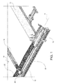
- Figure 1 partially shows the rearmost cross-member 14 and the intermediate cross-member 16 adjacent thereto, viewed from the outside of the sliding roof
- Figure 2 partially shows two adjacent intermediate cross-members 16, viewed from the inside of the sliding roof. It is clear that the following description relating to the intermediate cross-members shown in Figures 1 and 2 is applicable to all the intermediate cross-members, as well as to the end cross-members, forming part of the sliding roof. Likewise, the following description relating to the rearmost cross-member shown in Figure 1 is applicable to the foremost cross-member either.
- the rearmost cross-member 14 is fixed at its opposite ends to a pair of guide carriages 18, usually referred to as rearmost carriages, which are slidably arranged along the guide sections 12 to allow the rearmost cross-member 14 to move in the sliding direction x.
- each intermediate cross-member 16 is fixed at its opposite ends to a respective pair of guide carriages 20, usually referred to as intermediate carriages, which are slidably arranged along the guide sections 12 to allow the intermediate cross-members 16 to move in the sliding direction x.
- a respective link 22 is arranged between each pair of adjacent intermediate carriages 20, as well as between the rearmost carriage 18 and the intermediate carriage 20 adjacent thereto (and, in a manner not shown, between the foremost carriage and the intermediate carriage adjacent thereto).
- Each link 22 is preferably made of plastic material and is hinged at its opposite ends to the two carriages between which it is interposed. As far as the shape of the links 22 is concerned, reference is made to the explanation provided in the introductory part of the description of the present application.
- Each intermediate carriage 20 comprises a body 24 and a plurality of guide bearings 26, 28 by means of which the body 24 is slidably supported along the respective guide section 12 and is also restrained to the respective guide section 12.
- the body 24 comprises a first piece 30 of extruded aluminium alloy having a first extrusion direction x1 ( Figure 3 ) and a second piece 32 of extruded aluminium alloy having a second extrusion direction x2 ( Figure 3 ).
- first piece 30 is arranged with its extrusion direction x1 parallel to the sliding direction x
- second piece 32 is arranged with its extrusion direction x2 perpendicular to the sliding direction x, and hence perpendicular to the first extrusion direction x1.
- the first piece 30 integrally forms a first portion 34 with a substantially inverted U-shape, to which the guide bearings 26, 28 are fixed, and a second portion 36 arranged to be fixed (for instance by means of screw fixing members) to the end of the respective intermediate cross-member 16.
- the first portion 34 comprises a horizontal middle wall 38 (hereinafter simply referred to as middle wall) and a pair of vertical side walls 40 and 42 (hereinafter simply referred to as side walls), namely an inner side wall and an outer side wall, respectively, which extend downwards from opposite edges of the middle wall 38 which are parallel to the first extrusion direction x1.
- the middle wall 38 has a pair of holes 44 for insertion of respective screws 46, which serve both for fixing of the two pieces 30 and 32 to each other and for fixing of the guide bearings 26, which comprise each an idle roller rotatable about a vertical axis of rotation, to the assembly formed by the first and second pieces.
- the outer side wall 42 has a pair of holes 48 (only one of which is shown in Figure 4 ) for insertion of respective screws 50 for fixing of the guide bearings 28, which comprise each an idle roller rotatable about a horizontal axis of rotation.
- the rollers of the guide bearings 26 and 28 are arranged so as to roll along respective rolling surfaces of the guide sections 12.
- the second portion 36 is arranged adjacent to the inner side wall 40 of the first portion 34.
- the second piece 32 integrally forms a horizontal middle wall 52 (hereinafter simply referred to as middle wall), which in the mounted condition of the intermediate carriage rests on the middle wall 38 of the first piece 30, and a pair of connecting portions 54 which extend on opposite sides of the middle wall 52 and are suitably shaped so as to form respective seats 56 for hinged connection with the links 22.
- middle wall horizontal middle wall 52
- connecting portions 54 which extend on opposite sides of the middle wall 52 and are suitably shaped so as to form respective seats 56 for hinged connection with the links 22.
- the second piece comprises one connecting portion only, since each of these carriages is connected to one link only.
- the connecting portions 54 of the second piece 32 have each a slit 58 which communicates with the respective seat 56 and is shaped so as to allow snap insertion of respective hinge pins 60 integrally formed by the links 22 and to allow the hinge pins to be released only in a given angular position of the hinge pins different from the positions normally taken in use.
- the slit 58 has an opening angle ⁇ less than 180 degrees and the hinge pin 60 has a cross-section the outline of which is not wholly circular, but has a flat portion 62 and a step 64 joining the flat portion 62 to the remaining circular outline of the hinge pin.
- the slit 58 is oriented in such a manner that the bisecting line of the opening angle ⁇ of this slit is inclined by an acute angle towards the inside of the second piece 32 relative to the vertical direction.
- the flat portion 62 of the hinge pin 60 is oriented substantially parallel to the respective rigid leg of the link 22, whereby as long as the link rotates about the axis of the hinge pin between a horizontal position ( Figure 8A ) and a position (not shown) inclined less than 90 degrees relative to the horizontal direction, the hinge pin 60 remains engaged in the seat 56, since the size of the hinge pin in a direction perpendicular to the disengagement direction along which the pin is pulled out through the slit 58 (wherein said disengagement direction substantially coincides with the direction of the bisecting line of the opening angle ⁇ ) is larger than the width of the same slit.
- the bodies of the carriages being formed by pieces of extruded aluminium alloy, they have a high mechanical strength, which is higher than that of the carriages made of plastic material, and can at the same time be manufactured at a low cost, which is lower than the manufacturing cost of the carriages having a steel body.
- the carriages according to the invention have a lower weight than that of the carriages having a steel body.
- the fixing means being releasable fixing means and being used for fixing one or more further components of the intermediate carriages, a reduction in the overall number of components, and hence of the manufacturing costs, of the intermediate carriages, is obtained.
- the sliding roof of the present invention is applicable not only to lorries, semitrailers and the like, but also to containers, swap bodies, wagons and any other kind of container for rail transport.
Landscapes
- Engineering & Computer Science (AREA)
- Mechanical Engineering (AREA)
- Extrusion Of Metal (AREA)
- Tents Or Canopies (AREA)
- General Details Of Gearings (AREA)
Abstract
Description
- The present invention relates to a sliding roof, particularly for lorries, semitrailers and the like, and more specifically to the structure of the carriages of such a roof.
- As is known, the sliding roofs used on lorries, semitrailers and the like typically comprise a pair of guide sections arranged parallel to each other so as to define a sliding direction, a plurality of cross-members mounted on the guide sections so as to be able to slide along the sliding direction, and a tarpaulin secured to the cross-members. As far as the cross-members are concerned, a distinction is made between end cross-members and intermediate cross-members. The front end cross-member, simply referred to as the foremost cross-member, and the rear end cross-member, simply referred to as the rearmost cross-member, are configured each to perform the double function of securing the tarpaulin and of locking the roof in the closed condition. The intermediate cross-members are on the other hand configured to perform only the function of securing the tarpaulin. Each cross-member, be it an intermediate cross-member or an end cross-member, is guided along the guide sections by means of a respective pair of guide carriages, simply referred to as carriages, to which the opposite ends of the same cross-member are secured. Hereinafter, the carriages associated to the end cross-members will be referred to as end carriages, whereas the carriages associated to the intermediate cross-members will be referred to as intermediate carriages. An element usually known as link is arranged between each pair of adjacent intermediate carriages and comprises a pair of rigid legs, each hinged at a first end thereof (distal end) to a respective intermediate carriage, and an elastically deformable middle portion to which the second ends (proximal ends) of the legs are connected, the legs and the middle portion of the link being configured in such a manner that, as a result of two adjacent intermediate carriages moving towards each other, the middle portion, along with the proximal ends of the two legs, is raised relative to the guide section and the link takes an inverted V-shape configuration. Likewise, a respective link having the same structure as that of the links interposed between pairs of adjacent intermediate carriages is arranged between each end carriage and the adjacent intermediate carriage.
- The carriages are particularly critical components of the sliding roof. On the one hand, they are the components through which the tarpaulin is anchored to the guide sections, and hence to the structure of the lorry or of the semitrailer, and they must therefore be so strong as not to break as a result of the stresses applied on them for instance in case of strong wind or in case of snow drift on the tarpaulin. On the other hand, they must be low-cost components, so as not to affect negatively the overall cost of the sliding roof. Nowadays, the carriages are made either of steel, in which case they consist of several pieces joined to each other by welding, with resulting high manufacturing costs, or of plastic material, in which case the carriages are not able to ensure an acceptable mechanical strength.
- A sliding roof according to the preamble of the independent claim 1 is known from
DE 20 2005 005584 U1 . - It is an object of the present invention to provide a sliding roof of the above-identified type, the carriages of which have a high mechanical strength and a reduced weight and at the same time can be manufactured at a low cost.
- This and other objects are fully achieved according to the present invention by virtue of a sliding roof, particularly for lorries, semitrailers and the like, having the features set forth in the characterizing part of independent claim 1.
- Advantageous embodiments of the present invention are specified in the dependent claims, the content of which is to be regarded as an integral and integrating part of the following description.
- In short, the invention is based on the idea of providing a sliding roof in which each carriage has a body which is made of extruded aluminium alloy, and more specifically which comprises a first piece of extruded aluminium alloy having a first extrusion direction, a second piece of extruded aluminium alloy having a second extrusion direction and fixing means for fixing the first piece and the second piece to each other, wherein in the mounted condition of the sliding roof the first extrusion direction is oriented parallel to the sliding direction of the carriages along the guide sections and the second extrusion direction is oriented perpendicular to the sliding direction, i.e. perpendicular to the first extrusion direction.
- By virtue of the use of pieces of extruded aluminium alloy for the manufacturing of the bodies of the carriages, these have high mechanical strength and reduced weight and can at the same time be manufactured at a low cost.
- According to a preferred embodiment, the aforesaid fixing means are releasable fixing means, in particular screw connection means. In this case, the screw connection means are advantageously used to join one or more further components of the carriage, such as for instance guide bearings, with the assembly formed by the two pieces of extruded aluminium alloy. A reduction in the overall number of components, and hence in the manufacturing costs, of the carriages is thus obtained.
- Further features and advantages of the present invention will appear from the following detailed description, given purely by way of non-limiting example with reference to the appended drawings, in which:
-
Figures 1 and2 are perspective views which partially show, from different points of view, a sliding roof according to a preferred embodiment of the present invention; -
Figures 3 and 4 are a plan view from above and a side elevation view, respectively, of an intermediate carriage of the sliding roof ofFigures 1 and2 ; -
Figure 5 is a section view of an intermediate carriage taken through the section line V-V ofFigure 4 ; -
Figure 5 is a side elevation view of a first piece of extruded aluminium alloy of the intermediate carriage ofFigures 3 and 4 ; -
Figure 7 is a side elevation view of a second piece of extruded aluminium alloy of the intermediate carriage ofFigures 3 and 4 ; and -
Figures 8A to 8C are section views showing, in three different working positions, the hinged connection between the link and the second piece of the intermediate carriage ofFigures 3 and 4 . - With reference first to
Figures 1 and2 , a sliding roof according to a preferred embodiment of the present invention is generally indicated 10 and basically comprises: - a pair of guide sections 12 (only one of which is shown in
Figures 1 and2 ) arranged parallel to each other so as to define a sliding direction x (which, in case of a sliding roof installed on a lorry or semitrailer, is parallel to the longitudinal direction, i.e. the front-rear direction, of the lorry or semitrailer), - a plurality of
cross-members 14, 16 (end cross-members 14 and intermediate cross-members 16) mounted on theguide sections 12 so as to be able to slide along the sliding direction x, and - a tarpaulin (which is of per-se-known type and which is not shown in
Figures 1 and2 in order to allow to better understand the invention) secured to thecross-members - The
rear end cross-member 14, hereinafter simply referred to as therearmost cross-member 14, is configured to perform the double function of securing the tarpaulin and of locking the sliding roof. On the other hand, theintermediate cross-members 16 are configured to perform only the function of securing the tarpaulin.Figure 1 partially shows therearmost cross-member 14 and theintermediate cross-member 16 adjacent thereto, viewed from the outside of the sliding roof, whereasFigure 2 partially shows two adjacentintermediate cross-members 16, viewed from the inside of the sliding roof. It is clear that the following description relating to the intermediate cross-members shown inFigures 1 and2 is applicable to all the intermediate cross-members, as well as to the end cross-members, forming part of the sliding roof. Likewise, the following description relating to the rearmost cross-member shown inFigure 1 is applicable to the foremost cross-member either. - The
rearmost cross-member 14 is fixed at its opposite ends to a pair ofguide carriages 18, usually referred to as rearmost carriages, which are slidably arranged along theguide sections 12 to allow therearmost cross-member 14 to move in the sliding direction x. Likewise, eachintermediate cross-member 16 is fixed at its opposite ends to a respective pair ofguide carriages 20, usually referred to as intermediate carriages, which are slidably arranged along theguide sections 12 to allow theintermediate cross-members 16 to move in the sliding direction x. Arespective link 22 is arranged between each pair of adjacentintermediate carriages 20, as well as between therearmost carriage 18 and theintermediate carriage 20 adjacent thereto (and, in a manner not shown, between the foremost carriage and the intermediate carriage adjacent thereto). Eachlink 22 is preferably made of plastic material and is hinged at its opposite ends to the two carriages between which it is interposed. As far as the shape of thelinks 22 is concerned, reference is made to the explanation provided in the introductory part of the description of the present application. - With reference now in particular to
Figures 2 to 7 , the structure of theintermediate carriages 20 will be described, it being understood that what will be explained here below in connection with theintermediate carriages 20 is applicable as such (if not otherwise specified) to the end carriages (rearmost carriage 18 and foremost carriage). - Each
intermediate carriage 20 comprises abody 24 and a plurality ofguide bearings body 24 is slidably supported along therespective guide section 12 and is also restrained to therespective guide section 12. - More specifically, the
body 24 comprises afirst piece 30 of extruded aluminium alloy having a first extrusion direction x1 (Figure 3 ) and asecond piece 32 of extruded aluminium alloy having a second extrusion direction x2 (Figure 3 ). In the mounted condition, thefirst piece 30 is arranged with its extrusion direction x1 parallel to the sliding direction x, whereas thesecond piece 32 is arranged with its extrusion direction x2 perpendicular to the sliding direction x, and hence perpendicular to the first extrusion direction x1. - The
first piece 30 integrally forms afirst portion 34 with a substantially inverted U-shape, to which theguide bearings second portion 36 arranged to be fixed (for instance by means of screw fixing members) to the end of the respectiveintermediate cross-member 16. Thefirst portion 34 comprises a horizontal middle wall 38 (hereinafter simply referred to as middle wall) and a pair ofvertical side walls 40 and 42 (hereinafter simply referred to as side walls), namely an inner side wall and an outer side wall, respectively, which extend downwards from opposite edges of themiddle wall 38 which are parallel to the first extrusion direction x1. Themiddle wall 38 has a pair ofholes 44 for insertion ofrespective screws 46, which serve both for fixing of the twopieces guide bearings 26, which comprise each an idle roller rotatable about a vertical axis of rotation, to the assembly formed by the first and second pieces. Likewise, theouter side wall 42 has a pair of holes 48 (only one of which is shown inFigure 4 ) for insertion ofrespective screws 50 for fixing of theguide bearings 28, which comprise each an idle roller rotatable about a horizontal axis of rotation. In the mounted condition, as can be seen for instance inFigure 4 , the rollers of theguide bearings guide sections 12. Thesecond portion 36 is arranged adjacent to theinner side wall 40 of thefirst portion 34. - The
second piece 32 integrally forms a horizontal middle wall 52 (hereinafter simply referred to as middle wall), which in the mounted condition of the intermediate carriage rests on themiddle wall 38 of thefirst piece 30, and a pair of connectingportions 54 which extend on opposite sides of themiddle wall 52 and are suitably shaped so as to formrespective seats 56 for hinged connection with thelinks 22. Naturally, as far as the end carriages are concerned, the second piece comprises one connecting portion only, since each of these carriages is connected to one link only. - With reference now to
Figures 8A to 8C either, the connectingportions 54 of thesecond piece 32 have each aslit 58 which communicates with therespective seat 56 and is shaped so as to allow snap insertion ofrespective hinge pins 60 integrally formed by thelinks 22 and to allow the hinge pins to be released only in a given angular position of the hinge pins different from the positions normally taken in use. More specifically, theslit 58 has an opening angle α less than 180 degrees and thehinge pin 60 has a cross-section the outline of which is not wholly circular, but has aflat portion 62 and astep 64 joining theflat portion 62 to the remaining circular outline of the hinge pin. Theslit 58 is oriented in such a manner that the bisecting line of the opening angle α of this slit is inclined by an acute angle towards the inside of thesecond piece 32 relative to the vertical direction. Theflat portion 62 of thehinge pin 60 is oriented substantially parallel to the respective rigid leg of thelink 22, whereby as long as the link rotates about the axis of the hinge pin between a horizontal position (Figure 8A ) and a position (not shown) inclined less than 90 degrees relative to the horizontal direction, thehinge pin 60 remains engaged in theseat 56, since the size of the hinge pin in a direction perpendicular to the disengagement direction along which the pin is pulled out through the slit 58 (wherein said disengagement direction substantially coincides with the direction of the bisecting line of the opening angle α) is larger than the width of the same slit. In normal operating conditions, a hinged connection between the links and the carriages is therefore ensured. In order to disconnect a link from the respective carriage, the link must be rotated more than 90 degrees relative to the horizontal direction (as shown inFigure 8B ), until theflat portion 62 of thehinge pin 60 is arranged approximately parallel to the above-defined disengagement direction. In this position, thehinge pin 60 can be pulled out of theseat 56 through theslit 58, as shown inFigure 8C . - As already explained above, by virtue of the bodies of the carriages being formed by pieces of extruded aluminium alloy, they have a high mechanical strength, which is higher than that of the carriages made of plastic material, and can at the same time be manufactured at a low cost, which is lower than the manufacturing cost of the carriages having a steel body. Moreover, the carriages according to the invention have a lower weight than that of the carriages having a steel body. Furthermore, by virtue of the fixing means being releasable fixing means and being used for fixing one or more further components of the intermediate carriages, a reduction in the overall number of components, and hence of the manufacturing costs, of the intermediate carriages, is obtained.
- Naturally, the principle of the invention remaining unchanged, the embodiments and the constructional details may vary widely from those described and illustrated purely by way of non-limiting example.
- Clearly, the sliding roof of the present invention is applicable not only to lorries, semitrailers and the like, but also to containers, swap bodies, wagons and any other kind of container for rail transport.
Claims (10)
- Sliding roof (10), particularly for lorries, semitrailers and the like, comprising a pair of guide sections (12) arranged parallel to each other so as to define a sliding direction (x), a plurality of cross-members (14, 16) mounted on the guide sections (12) so as to be slidable along the sliding direction (x), and a tarpaulin secured to the cross-members (14, 16), wherein to the opposite ends of each cross-member (14, 16) there are attached a pair of carriages (18, 20) by means of which the cross-member (14, 16) is guided along the guide sections (12), wherein each carriage (18, 20) comprises a body (24) and a plurality of guide bearings (26, 28) carried by the body (24),
characterized in that the body (24) of each carriage (18, 20) comprises a first piece (30) of extruded aluminium alloy having a first extrusion direction (x1), a second piece (32) of extruded aluminium alloy having a second extrusion direction (x2), and fixing means (46) for fixing the first piece (30) and the second piece (32) to each other, and in that the first and second pieces (30, 32) are arranged in such a manner that the first extrusion direction (x1) is oriented parallel to the sliding direction (x), whereas the second extrusion direction (x2) is oriented perpendicular to the sliding direction (x). - Sliding roof according to claim 1, wherein the first piece (30) of each carriage (18, 20) integrally forms a first portion (34) which has substantially an inverted U-shape and to which the guide bearings (26, 28) are fixed, and a second portion (36) which is fixed to an end of the respective cross-member (14, 16).
- Sliding roof according to claim 2, wherein the first portion (34) comprises a horizontal middle wall (38) and a pair of vertical side walls (40, 42), that is to say, an inner vertical side wall and on outer vertical side wall, respectively, which extend downwards from opposite sides of the horizontal middle wall (38) parallel to the first extrusion direction (x1), wherein the horizontal middle wall (38) has first holes (44) for insertion of respective first screws (46) as fixing means for fixing the first piece (30) and the second piece (32) to each other.
- Sliding roof according to claim 3, wherein said plurality of guide bearings (26, 28) comprise first vertical-axis guide bearings (26), and wherein said first guide bearings (26) are fixed to the body (24) by means of said first screws (46).
- Sliding roof according to claim 3 or claim 4, wherein said plurality of guide bearings (26, 28) comprise second horizontal-axis guide bearings (28), wherein the outer side wall (42) has second holes (48) for insertion of respective second screws (50), and wherein said second guide bearings (28) are fixed to the body (24) by means of said second screws (50).
- Sliding roof according to any of claims 3 to 5, wherein the second portion (36) is arranged adjacent to the inner side wall (40) of the first portion (34).
- Sliding roof according to any of claims 3 to 6, wherein the second piece (32) of each carriage (18, 20) integrally forms a horizontal middle wall (52) resting on the horizontal middle wall (38) of the first piece (30), and at least one connection portion (54) which extends from the horizontal middle wall (52) and forms a respective hinge seat (56).
- Sliding roof according to claim 7, further comprising a plurality of links (22) each provided with a pair of hinge pins (60) for hinged connection of each link (22) with the pair of adjacent carriages (18, 20), wherein the hinge seats (56) of each carriage (20) and the hinge pins (60) of each link (22) are configured so as to allow the hinge pins (60) to be released only in a given angular position of the hinge pins (60) different from those normally taken in use.
- Sliding roof according to claim 8, wherein each hinge seat (56) has a slit (58) and wherein said slit (58) has an opening angle (α) smaller than 180 degrees and is oriented in such a manner that the bisecting line of the opening angle (α) is inclined by an acute angle towards the inside of the second piece (32) relative to the vertical direction.
- Sliding roof according to claim 9, wherein each link (22) comprises a pair of rigid legs each forming at a first end thereof a respective hinge pin (60), and a resiliently deformable middle portion to which the second ends of the legs are connected, wherein each hinge pin (60) has a cross-section the outline of which is not wholly circular, but has a flat portion (62) and a step (64) joining the flat portion (62) to the remaining circular outline of the hinge pin (60), and wherein the flat portion (62) of each hinge pin (60) is oriented substantially parallel to the rigid leg of the link (22) forming said hinge pin.
Applications Claiming Priority (1)
| Application Number | Priority Date | Filing Date | Title |
|---|---|---|---|
| ITTO2010A001010A IT1403781B1 (en) | 2010-12-17 | 2010-12-17 | SLIDING COVER, PARTICULARLY FOR TRUCKS, SEMI-TRAILERS AND SIMILAR, WITH EXTRUDED ALUMINUM ALLOY TROLLEYS |
Publications (2)
| Publication Number | Publication Date |
|---|---|
| EP2465718A1 true EP2465718A1 (en) | 2012-06-20 |
| EP2465718B1 EP2465718B1 (en) | 2014-02-19 |
Family
ID=43737400
Family Applications (1)
| Application Number | Title | Priority Date | Filing Date |
|---|---|---|---|
| EP20110189368 Not-in-force EP2465718B1 (en) | 2010-12-17 | 2011-11-16 | Sliding roof, particularly for lorries, semitrailers and the like, with carriages made of extruded aluminium alloy |
Country Status (2)
| Country | Link |
|---|---|
| EP (1) | EP2465718B1 (en) |
| IT (1) | IT1403781B1 (en) |
Cited By (4)
| Publication number | Priority date | Publication date | Assignee | Title |
|---|---|---|---|---|
| DE202015002704U1 (en) * | 2015-04-10 | 2016-07-13 | Liebherr-Werk Nenzing Gmbh | Construction or transhipment machine |
| EP2759434A3 (en) * | 2013-01-23 | 2018-04-25 | BOGE Elastmetall GmbH | Roller carriage and modular construction system for a roller carriage for a slidable top structure of a truck |
| EP4265452A1 (en) * | 2022-04-22 | 2023-10-25 | Fruehauf | Mechanism configured to articulate a cover structure for a vehicle, and such a mechanism |
| DE102013003222B4 (en) * | 2012-02-27 | 2026-01-29 | European Trailer Systems Gmbh | Canopy frame for a tarpaulin superstructure, as well as shaft section and sled. |
Citations (7)
| Publication number | Priority date | Publication date | Assignee | Title |
|---|---|---|---|---|
| DE9312295U1 (en) * | 1992-08-26 | 1994-01-27 | Pommier & Cie, Saint-Ouen L'aumone, Val D'oise | Trolley for the movable post of a tarpaulin vehicle |
| DE29700177U1 (en) * | 1996-10-08 | 1997-03-13 | Ed. Scharwächter GmbH & Co. Fahrzeugtechnik, 94491 Hengersberg | Soft top system for commercial vehicles |
| EP0778169A1 (en) * | 1995-12-08 | 1997-06-11 | POMMIER & CIE | Tarpaulin arrangement for lorries |
| DE29815722U1 (en) * | 1998-09-01 | 2000-01-13 | Edscha LKW-Schiebeverdecke GmbH, 94491 Hengersberg | Foldable tarpaulin structure for vehicle bodies and containers |
| DE29724563U1 (en) * | 1997-12-19 | 2002-02-28 | Kögel Fahrzeugwerke AG, 89079 Ulm | Commercial vehicle structure |
| DE202005005584U1 (en) | 2005-04-07 | 2006-08-10 | Edscha Lkw-Schiebeverdecke Gmbh | Cover frame for tarpaulin construction has slides each form-fitting in corresponding guide section of two adjacent flaps, wherein adjacent flaps are constructed to inter-engage |
| DE102005028538A1 (en) * | 2005-06-19 | 2006-12-21 | Edscha Lkw-Schiebeverdecke Gmbh | Cover frame for tilt structure has bearing sector on carriage with vertically aligned horizontal bearing roller and horizontally aligned vertical guide roller |
-
2010
- 2010-12-17 IT ITTO2010A001010A patent/IT1403781B1/en active
-
2011
- 2011-11-16 EP EP20110189368 patent/EP2465718B1/en not_active Not-in-force
Patent Citations (7)
| Publication number | Priority date | Publication date | Assignee | Title |
|---|---|---|---|---|
| DE9312295U1 (en) * | 1992-08-26 | 1994-01-27 | Pommier & Cie, Saint-Ouen L'aumone, Val D'oise | Trolley for the movable post of a tarpaulin vehicle |
| EP0778169A1 (en) * | 1995-12-08 | 1997-06-11 | POMMIER & CIE | Tarpaulin arrangement for lorries |
| DE29700177U1 (en) * | 1996-10-08 | 1997-03-13 | Ed. Scharwächter GmbH & Co. Fahrzeugtechnik, 94491 Hengersberg | Soft top system for commercial vehicles |
| DE29724563U1 (en) * | 1997-12-19 | 2002-02-28 | Kögel Fahrzeugwerke AG, 89079 Ulm | Commercial vehicle structure |
| DE29815722U1 (en) * | 1998-09-01 | 2000-01-13 | Edscha LKW-Schiebeverdecke GmbH, 94491 Hengersberg | Foldable tarpaulin structure for vehicle bodies and containers |
| DE202005005584U1 (en) | 2005-04-07 | 2006-08-10 | Edscha Lkw-Schiebeverdecke Gmbh | Cover frame for tarpaulin construction has slides each form-fitting in corresponding guide section of two adjacent flaps, wherein adjacent flaps are constructed to inter-engage |
| DE102005028538A1 (en) * | 2005-06-19 | 2006-12-21 | Edscha Lkw-Schiebeverdecke Gmbh | Cover frame for tilt structure has bearing sector on carriage with vertically aligned horizontal bearing roller and horizontally aligned vertical guide roller |
Cited By (5)
| Publication number | Priority date | Publication date | Assignee | Title |
|---|---|---|---|---|
| DE102013003222B4 (en) * | 2012-02-27 | 2026-01-29 | European Trailer Systems Gmbh | Canopy frame for a tarpaulin superstructure, as well as shaft section and sled. |
| EP2759434A3 (en) * | 2013-01-23 | 2018-04-25 | BOGE Elastmetall GmbH | Roller carriage and modular construction system for a roller carriage for a slidable top structure of a truck |
| DE202015002704U1 (en) * | 2015-04-10 | 2016-07-13 | Liebherr-Werk Nenzing Gmbh | Construction or transhipment machine |
| EP4265452A1 (en) * | 2022-04-22 | 2023-10-25 | Fruehauf | Mechanism configured to articulate a cover structure for a vehicle, and such a mechanism |
| FR3134756A1 (en) * | 2022-04-22 | 2023-10-27 | Fruehauf | Mechanism configured to articulate a covering structure for a vehicle, and such a mechanism |
Also Published As
| Publication number | Publication date |
|---|---|
| ITTO20101010A1 (en) | 2012-06-18 |
| IT1403781B1 (en) | 2013-10-31 |
| EP2465718B1 (en) | 2014-02-19 |
Similar Documents
| Publication | Publication Date | Title |
|---|---|---|
| US10882384B2 (en) | Tarpaulin structure | |
| EP2465718B1 (en) | Sliding roof, particularly for lorries, semitrailers and the like, with carriages made of extruded aluminium alloy | |
| CN208393499U (en) | vehicle and truck | |
| EP2329991B1 (en) | Safety device for a vehicle interior | |
| US20110127790A1 (en) | Device capable of modulation by expansion or compaction for forming a protection and transport structure at the back and at the height of the roof of the passenger compartment of an automotive vehicle | |
| US20100295337A1 (en) | Simultaneous single rail movement system for a vehicle door ii | |
| CN101566032A (en) | Sliding door roller bracket track extension with interlock | |
| AT503828A1 (en) | LOADING FLOOR FOR A LOADING AREA OF A VEHICLE | |
| KR100359300B1 (en) | Passenger-carrying or estate-type motor car | |
| US9914372B2 (en) | Motor vehicle seat arrangement | |
| DE102016205055B4 (en) | Vehicle, in particular Reisewohnmobil and Gurtblocksystem this | |
| EP3210808B1 (en) | Canvas roller and industrial vehicle with canvas cover | |
| EP2116420B1 (en) | Box body with a panel with a fixing device | |
| PL199035B1 (en) | Bow configuration | |
| CN103068603B (en) | Slide roof construction, sliding top system, there is the truck of sliding top system, there is the side curtain trailer of sliding top system | |
| CN210174866U (en) | Top cover device and railway wagon | |
| DE102008019162B4 (en) | vehicle body | |
| FI97458B (en) | Tilting transfer wall structure of a railway freight wagon | |
| CN116176400B (en) | Transport rack and usage | |
| DE4237410C2 (en) | Platform body for swap bodies and fixed bodies | |
| WO2016202565A1 (en) | Luggage compartment cover for a motor vehicle | |
| AT414114B (en) | Runge | |
| KR200474049Y1 (en) | Foldable tent for a truck | |
| EP0936123B1 (en) | Carrier wagon for the transport of containers or interchangeable containers on the railway network | |
| BE1029041B1 (en) | Sliding roof system |
Legal Events
| Date | Code | Title | Description |
|---|---|---|---|
| PUAI | Public reference made under article 153(3) epc to a published international application that has entered the european phase |
Free format text: ORIGINAL CODE: 0009012 |
|
| 17P | Request for examination filed |
Effective date: 20111116 |
|
| AK | Designated contracting states |
Kind code of ref document: A1 Designated state(s): AL AT BE BG CH CY CZ DE DK EE ES FI FR GB GR HR HU IE IS IT LI LT LU LV MC MK MT NL NO PL PT RO RS SE SI SK SM TR |
|
| AX | Request for extension of the european patent |
Extension state: BA ME |
|
| GRAP | Despatch of communication of intention to grant a patent |
Free format text: ORIGINAL CODE: EPIDOSNIGR1 |
|
| RIC1 | Information provided on ipc code assigned before grant |
Ipc: B60J 7/06 20060101AFI20130322BHEP |
|
| INTG | Intention to grant announced |
Effective date: 20130423 |
|
| GRAS | Grant fee paid |
Free format text: ORIGINAL CODE: EPIDOSNIGR3 |
|
| GRAP | Despatch of communication of intention to grant a patent |
Free format text: ORIGINAL CODE: EPIDOSNIGR1 |
|
| INTG | Intention to grant announced |
Effective date: 20130912 |
|
| GRAA | (expected) grant |
Free format text: ORIGINAL CODE: 0009210 |
|
| AK | Designated contracting states |
Kind code of ref document: B1 Designated state(s): AL AT BE BG CH CY CZ DE DK EE ES FI FR GB GR HR HU IE IS IT LI LT LU LV MC MK MT NL NO PL PT RO RS SE SI SK SM TR |
|
| REG | Reference to a national code |
Ref country code: GB Ref legal event code: FG4D |
|
| REG | Reference to a national code |
Ref country code: CH Ref legal event code: EP |
|
| REG | Reference to a national code |
Ref country code: AT Ref legal event code: REF Ref document number: 652734 Country of ref document: AT Kind code of ref document: T Effective date: 20140315 |
|
| REG | Reference to a national code |
Ref country code: DE Ref legal event code: R096 Ref document number: 602011004979 Country of ref document: DE Effective date: 20140403 |
|
| REG | Reference to a national code |
Ref country code: IE Ref legal event code: FG4D |
|
| REG | Reference to a national code |
Ref country code: NL Ref legal event code: VDEP Effective date: 20140219 |
|
| REG | Reference to a national code |
Ref country code: AT Ref legal event code: MK05 Ref document number: 652734 Country of ref document: AT Kind code of ref document: T Effective date: 20140219 |
|
| REG | Reference to a national code |
Ref country code: LT Ref legal event code: MG4D |
|
| PG25 | Lapsed in a contracting state [announced via postgrant information from national office to epo] |
Ref country code: LT Free format text: LAPSE BECAUSE OF FAILURE TO SUBMIT A TRANSLATION OF THE DESCRIPTION OR TO PAY THE FEE WITHIN THE PRESCRIBED TIME-LIMIT Effective date: 20140219 Ref country code: NO Free format text: LAPSE BECAUSE OF FAILURE TO SUBMIT A TRANSLATION OF THE DESCRIPTION OR TO PAY THE FEE WITHIN THE PRESCRIBED TIME-LIMIT Effective date: 20140519 Ref country code: IS Free format text: LAPSE BECAUSE OF FAILURE TO SUBMIT A TRANSLATION OF THE DESCRIPTION OR TO PAY THE FEE WITHIN THE PRESCRIBED TIME-LIMIT Effective date: 20140619 |
|
| PG25 | Lapsed in a contracting state [announced via postgrant information from national office to epo] |
Ref country code: FI Free format text: LAPSE BECAUSE OF FAILURE TO SUBMIT A TRANSLATION OF THE DESCRIPTION OR TO PAY THE FEE WITHIN THE PRESCRIBED TIME-LIMIT Effective date: 20140219 Ref country code: AT Free format text: LAPSE BECAUSE OF FAILURE TO SUBMIT A TRANSLATION OF THE DESCRIPTION OR TO PAY THE FEE WITHIN THE PRESCRIBED TIME-LIMIT Effective date: 20140219 Ref country code: SE Free format text: LAPSE BECAUSE OF FAILURE TO SUBMIT A TRANSLATION OF THE DESCRIPTION OR TO PAY THE FEE WITHIN THE PRESCRIBED TIME-LIMIT Effective date: 20140219 Ref country code: PT Free format text: LAPSE BECAUSE OF FAILURE TO SUBMIT A TRANSLATION OF THE DESCRIPTION OR TO PAY THE FEE WITHIN THE PRESCRIBED TIME-LIMIT Effective date: 20140619 Ref country code: ES Free format text: LAPSE BECAUSE OF FAILURE TO SUBMIT A TRANSLATION OF THE DESCRIPTION OR TO PAY THE FEE WITHIN THE PRESCRIBED TIME-LIMIT Effective date: 20140219 Ref country code: CY Free format text: LAPSE BECAUSE OF FAILURE TO SUBMIT A TRANSLATION OF THE DESCRIPTION OR TO PAY THE FEE WITHIN THE PRESCRIBED TIME-LIMIT Effective date: 20140219 Ref country code: NL Free format text: LAPSE BECAUSE OF FAILURE TO SUBMIT A TRANSLATION OF THE DESCRIPTION OR TO PAY THE FEE WITHIN THE PRESCRIBED TIME-LIMIT Effective date: 20140219 |
|
| PG25 | Lapsed in a contracting state [announced via postgrant information from national office to epo] |
Ref country code: HR Free format text: LAPSE BECAUSE OF FAILURE TO SUBMIT A TRANSLATION OF THE DESCRIPTION OR TO PAY THE FEE WITHIN THE PRESCRIBED TIME-LIMIT Effective date: 20140219 Ref country code: LV Free format text: LAPSE BECAUSE OF FAILURE TO SUBMIT A TRANSLATION OF THE DESCRIPTION OR TO PAY THE FEE WITHIN THE PRESCRIBED TIME-LIMIT Effective date: 20140219 Ref country code: BE Free format text: LAPSE BECAUSE OF FAILURE TO SUBMIT A TRANSLATION OF THE DESCRIPTION OR TO PAY THE FEE WITHIN THE PRESCRIBED TIME-LIMIT Effective date: 20140219 Ref country code: RS Free format text: LAPSE BECAUSE OF FAILURE TO SUBMIT A TRANSLATION OF THE DESCRIPTION OR TO PAY THE FEE WITHIN THE PRESCRIBED TIME-LIMIT Effective date: 20140219 |
|
| PG25 | Lapsed in a contracting state [announced via postgrant information from national office to epo] |
Ref country code: RO Free format text: LAPSE BECAUSE OF FAILURE TO SUBMIT A TRANSLATION OF THE DESCRIPTION OR TO PAY THE FEE WITHIN THE PRESCRIBED TIME-LIMIT Effective date: 20140219 Ref country code: DK Free format text: LAPSE BECAUSE OF FAILURE TO SUBMIT A TRANSLATION OF THE DESCRIPTION OR TO PAY THE FEE WITHIN THE PRESCRIBED TIME-LIMIT Effective date: 20140219 Ref country code: EE Free format text: LAPSE BECAUSE OF FAILURE TO SUBMIT A TRANSLATION OF THE DESCRIPTION OR TO PAY THE FEE WITHIN THE PRESCRIBED TIME-LIMIT Effective date: 20140219 Ref country code: CZ Free format text: LAPSE BECAUSE OF FAILURE TO SUBMIT A TRANSLATION OF THE DESCRIPTION OR TO PAY THE FEE WITHIN THE PRESCRIBED TIME-LIMIT Effective date: 20140219 |
|
| REG | Reference to a national code |
Ref country code: DE Ref legal event code: R097 Ref document number: 602011004979 Country of ref document: DE |
|
| PG25 | Lapsed in a contracting state [announced via postgrant information from national office to epo] |
Ref country code: SK Free format text: LAPSE BECAUSE OF FAILURE TO SUBMIT A TRANSLATION OF THE DESCRIPTION OR TO PAY THE FEE WITHIN THE PRESCRIBED TIME-LIMIT Effective date: 20140219 Ref country code: PL Free format text: LAPSE BECAUSE OF FAILURE TO SUBMIT A TRANSLATION OF THE DESCRIPTION OR TO PAY THE FEE WITHIN THE PRESCRIBED TIME-LIMIT Effective date: 20140219 |
|
| PLBE | No opposition filed within time limit |
Free format text: ORIGINAL CODE: 0009261 |
|
| STAA | Information on the status of an ep patent application or granted ep patent |
Free format text: STATUS: NO OPPOSITION FILED WITHIN TIME LIMIT |
|
| 26N | No opposition filed |
Effective date: 20141120 |
|
| PG25 | Lapsed in a contracting state [announced via postgrant information from national office to epo] |
Ref country code: RS Free format text: LAPSE BECAUSE OF FAILURE TO SUBMIT A TRANSLATION OF THE DESCRIPTION OR TO PAY THE FEE WITHIN THE PRESCRIBED TIME-LIMIT Effective date: 20140903 |
|
| REG | Reference to a national code |
Ref country code: DE Ref legal event code: R097 Ref document number: 602011004979 Country of ref document: DE Effective date: 20141120 |
|
| PG25 | Lapsed in a contracting state [announced via postgrant information from national office to epo] |
Ref country code: IT Free format text: LAPSE BECAUSE OF FAILURE TO SUBMIT A TRANSLATION OF THE DESCRIPTION OR TO PAY THE FEE WITHIN THE PRESCRIBED TIME-LIMIT Effective date: 20140219 |
|
| PG25 | Lapsed in a contracting state [announced via postgrant information from national office to epo] |
Ref country code: SI Free format text: LAPSE BECAUSE OF FAILURE TO SUBMIT A TRANSLATION OF THE DESCRIPTION OR TO PAY THE FEE WITHIN THE PRESCRIBED TIME-LIMIT Effective date: 20140219 |
|
| REG | Reference to a national code |
Ref country code: DE Ref legal event code: R119 Ref document number: 602011004979 Country of ref document: DE |
|
| PG25 | Lapsed in a contracting state [announced via postgrant information from national office to epo] |
Ref country code: MC Free format text: LAPSE BECAUSE OF FAILURE TO SUBMIT A TRANSLATION OF THE DESCRIPTION OR TO PAY THE FEE WITHIN THE PRESCRIBED TIME-LIMIT Effective date: 20140219 Ref country code: LU Free format text: LAPSE BECAUSE OF FAILURE TO SUBMIT A TRANSLATION OF THE DESCRIPTION OR TO PAY THE FEE WITHIN THE PRESCRIBED TIME-LIMIT Effective date: 20141116 |
|
| REG | Reference to a national code |
Ref country code: CH Ref legal event code: PL |
|
| PG25 | Lapsed in a contracting state [announced via postgrant information from national office to epo] |
Ref country code: LI Free format text: LAPSE BECAUSE OF NON-PAYMENT OF DUE FEES Effective date: 20141130 Ref country code: CH Free format text: LAPSE BECAUSE OF NON-PAYMENT OF DUE FEES Effective date: 20141130 |
|
| REG | Reference to a national code |
Ref country code: IE Ref legal event code: MM4A |
|
| REG | Reference to a national code |
Ref country code: FR Ref legal event code: ST Effective date: 20150731 |
|
| PG25 | Lapsed in a contracting state [announced via postgrant information from national office to epo] |
Ref country code: IE Free format text: LAPSE BECAUSE OF NON-PAYMENT OF DUE FEES Effective date: 20141116 Ref country code: DE Free format text: LAPSE BECAUSE OF NON-PAYMENT OF DUE FEES Effective date: 20150602 |
|
| PG25 | Lapsed in a contracting state [announced via postgrant information from national office to epo] |
Ref country code: FR Free format text: LAPSE BECAUSE OF NON-PAYMENT OF DUE FEES Effective date: 20141201 |
|
| PG25 | Lapsed in a contracting state [announced via postgrant information from national office to epo] |
Ref country code: SM Free format text: LAPSE BECAUSE OF FAILURE TO SUBMIT A TRANSLATION OF THE DESCRIPTION OR TO PAY THE FEE WITHIN THE PRESCRIBED TIME-LIMIT Effective date: 20140219 |
|
| PG25 | Lapsed in a contracting state [announced via postgrant information from national office to epo] |
Ref country code: BG Free format text: LAPSE BECAUSE OF FAILURE TO SUBMIT A TRANSLATION OF THE DESCRIPTION OR TO PAY THE FEE WITHIN THE PRESCRIBED TIME-LIMIT Effective date: 20140219 Ref country code: GR Free format text: LAPSE BECAUSE OF FAILURE TO SUBMIT A TRANSLATION OF THE DESCRIPTION OR TO PAY THE FEE WITHIN THE PRESCRIBED TIME-LIMIT Effective date: 20140520 |
|
| GBPC | Gb: european patent ceased through non-payment of renewal fee |
Effective date: 20151116 |
|
| PG25 | Lapsed in a contracting state [announced via postgrant information from national office to epo] |
Ref country code: MT Free format text: LAPSE BECAUSE OF FAILURE TO SUBMIT A TRANSLATION OF THE DESCRIPTION OR TO PAY THE FEE WITHIN THE PRESCRIBED TIME-LIMIT Effective date: 20140219 Ref country code: HU Free format text: LAPSE BECAUSE OF FAILURE TO SUBMIT A TRANSLATION OF THE DESCRIPTION OR TO PAY THE FEE WITHIN THE PRESCRIBED TIME-LIMIT; INVALID AB INITIO Effective date: 20111116 Ref country code: TR Free format text: LAPSE BECAUSE OF FAILURE TO SUBMIT A TRANSLATION OF THE DESCRIPTION OR TO PAY THE FEE WITHIN THE PRESCRIBED TIME-LIMIT Effective date: 20140219 |
|
| PG25 | Lapsed in a contracting state [announced via postgrant information from national office to epo] |
Ref country code: GB Free format text: LAPSE BECAUSE OF NON-PAYMENT OF DUE FEES Effective date: 20151116 |
|
| PG25 | Lapsed in a contracting state [announced via postgrant information from national office to epo] |
Ref country code: MK Free format text: LAPSE BECAUSE OF FAILURE TO SUBMIT A TRANSLATION OF THE DESCRIPTION OR TO PAY THE FEE WITHIN THE PRESCRIBED TIME-LIMIT Effective date: 20140219 |
|
| PG25 | Lapsed in a contracting state [announced via postgrant information from national office to epo] |
Ref country code: AL Free format text: LAPSE BECAUSE OF FAILURE TO SUBMIT A TRANSLATION OF THE DESCRIPTION OR TO PAY THE FEE WITHIN THE PRESCRIBED TIME-LIMIT Effective date: 20140219 |