EP2465586A1 - Golf ball deburring apparatus - Google Patents
Golf ball deburring apparatus Download PDFInfo
- Publication number
- EP2465586A1 EP2465586A1 EP11193554A EP11193554A EP2465586A1 EP 2465586 A1 EP2465586 A1 EP 2465586A1 EP 11193554 A EP11193554 A EP 11193554A EP 11193554 A EP11193554 A EP 11193554A EP 2465586 A1 EP2465586 A1 EP 2465586A1
- Authority
- EP
- European Patent Office
- Prior art keywords
- ball
- arm
- deburring
- finger
- holder
- Prior art date
- Legal status (The legal status is an assumption and is not a legal conclusion. Google has not performed a legal analysis and makes no representation as to the accuracy of the status listed.)
- Granted
Links
- 239000012530 fluid Substances 0.000 claims description 18
- 230000033001 locomotion Effects 0.000 claims description 12
- 239000003082 abrasive agent Substances 0.000 claims description 6
- 239000000463 material Substances 0.000 description 27
- 238000011282 treatment Methods 0.000 description 26
- 239000010410 layer Substances 0.000 description 22
- 238000000034 method Methods 0.000 description 19
- 238000003780 insertion Methods 0.000 description 14
- 230000037431 insertion Effects 0.000 description 14
- 238000000465 moulding Methods 0.000 description 11
- 238000005299 abrasion Methods 0.000 description 10
- 230000005540 biological transmission Effects 0.000 description 9
- 239000007924 injection Substances 0.000 description 9
- 238000002347 injection Methods 0.000 description 9
- 230000008859 change Effects 0.000 description 8
- 230000008569 process Effects 0.000 description 7
- 230000013011 mating Effects 0.000 description 6
- 238000013461 design Methods 0.000 description 4
- 230000006378 damage Effects 0.000 description 3
- 238000001746 injection moulding Methods 0.000 description 3
- 230000007246 mechanism Effects 0.000 description 3
- 229930091051 Arenine Natural products 0.000 description 2
- 230000009471 action Effects 0.000 description 2
- 230000006866 deterioration Effects 0.000 description 2
- 239000013618 particulate matter Substances 0.000 description 2
- 239000008262 pumice Substances 0.000 description 2
- 229920005989 resin Polymers 0.000 description 2
- 239000011347 resin Substances 0.000 description 2
- 229920003182 Surlyn® Polymers 0.000 description 1
- 239000000853 adhesive Substances 0.000 description 1
- 230000001070 adhesive effect Effects 0.000 description 1
- 238000004891 communication Methods 0.000 description 1
- 230000001419 dependent effect Effects 0.000 description 1
- 230000000694 effects Effects 0.000 description 1
- 230000003993 interaction Effects 0.000 description 1
- 238000004519 manufacturing process Methods 0.000 description 1
- 239000002184 metal Substances 0.000 description 1
- 238000012986 modification Methods 0.000 description 1
- 230000004048 modification Effects 0.000 description 1
- 239000004033 plastic Substances 0.000 description 1
- 229920003023 plastic Polymers 0.000 description 1
- 238000003825 pressing Methods 0.000 description 1
- 230000001681 protective effect Effects 0.000 description 1
- 230000009467 reduction Effects 0.000 description 1
- 239000002356 single layer Substances 0.000 description 1
- 239000012899 standard injection Substances 0.000 description 1
- 239000002344 surface layer Substances 0.000 description 1
- 229920002803 thermoplastic polyurethane Polymers 0.000 description 1
Images



Classifications
-
- A—HUMAN NECESSITIES
- A63—SPORTS; GAMES; AMUSEMENTS
- A63B—APPARATUS FOR PHYSICAL TRAINING, GYMNASTICS, SWIMMING, CLIMBING, OR FENCING; BALL GAMES; TRAINING EQUIPMENT
- A63B47/00—Devices for handling or treating balls, e.g. for holding or carrying balls
-
- A—HUMAN NECESSITIES
- A63—SPORTS; GAMES; AMUSEMENTS
- A63B—APPARATUS FOR PHYSICAL TRAINING, GYMNASTICS, SWIMMING, CLIMBING, OR FENCING; BALL GAMES; TRAINING EQUIPMENT
- A63B47/00—Devices for handling or treating balls, e.g. for holding or carrying balls
- A63B47/04—Devices for handling or treating balls, e.g. for holding or carrying balls for cleaning balls
-
- A—HUMAN NECESSITIES
- A63—SPORTS; GAMES; AMUSEMENTS
- A63B—APPARATUS FOR PHYSICAL TRAINING, GYMNASTICS, SWIMMING, CLIMBING, OR FENCING; BALL GAMES; TRAINING EQUIPMENT
- A63B45/00—Apparatus or methods for manufacturing balls
-
- B—PERFORMING OPERATIONS; TRANSPORTING
- B24—GRINDING; POLISHING
- B24B—MACHINES, DEVICES, OR PROCESSES FOR GRINDING OR POLISHING; DRESSING OR CONDITIONING OF ABRADING SURFACES; FEEDING OF GRINDING, POLISHING, OR LAPPING AGENTS
- B24B11/00—Machines or devices designed for grinding spherical surfaces or parts of spherical surfaces on work; Accessories therefor
- B24B11/02—Machines or devices designed for grinding spherical surfaces or parts of spherical surfaces on work; Accessories therefor for grinding balls
-
- B—PERFORMING OPERATIONS; TRANSPORTING
- B24—GRINDING; POLISHING
- B24B—MACHINES, DEVICES, OR PROCESSES FOR GRINDING OR POLISHING; DRESSING OR CONDITIONING OF ABRADING SURFACES; FEEDING OF GRINDING, POLISHING, OR LAPPING AGENTS
- B24B9/00—Machines or devices designed for grinding edges or bevels on work or for removing burrs; Accessories therefor
- B24B9/02—Machines or devices designed for grinding edges or bevels on work or for removing burrs; Accessories therefor characterised by a special design with respect to properties of materials specific to articles to be ground
- B24B9/20—Machines or devices designed for grinding edges or bevels on work or for removing burrs; Accessories therefor characterised by a special design with respect to properties of materials specific to articles to be ground of plastics
-
- B—PERFORMING OPERATIONS; TRANSPORTING
- B29—WORKING OF PLASTICS; WORKING OF SUBSTANCES IN A PLASTIC STATE IN GENERAL
- B29C—SHAPING OR JOINING OF PLASTICS; SHAPING OF MATERIAL IN A PLASTIC STATE, NOT OTHERWISE PROVIDED FOR; AFTER-TREATMENT OF THE SHAPED PRODUCTS, e.g. REPAIRING
- B29C37/00—Component parts, details, accessories or auxiliary operations, not covered by group B29C33/00 or B29C35/00
- B29C37/02—Deburring or deflashing
-
- A—HUMAN NECESSITIES
- A63—SPORTS; GAMES; AMUSEMENTS
- A63B—APPARATUS FOR PHYSICAL TRAINING, GYMNASTICS, SWIMMING, CLIMBING, OR FENCING; BALL GAMES; TRAINING EQUIPMENT
- A63B37/00—Solid balls; Rigid hollow balls; Marbles
- A63B37/0003—Golf balls
-
- B—PERFORMING OPERATIONS; TRANSPORTING
- B29—WORKING OF PLASTICS; WORKING OF SUBSTANCES IN A PLASTIC STATE IN GENERAL
- B29C—SHAPING OR JOINING OF PLASTICS; SHAPING OF MATERIAL IN A PLASTIC STATE, NOT OTHERWISE PROVIDED FOR; AFTER-TREATMENT OF THE SHAPED PRODUCTS, e.g. REPAIRING
- B29C37/00—Component parts, details, accessories or auxiliary operations, not covered by group B29C33/00 or B29C35/00
- B29C2037/90—Measuring, controlling or regulating
- B29C2037/903—Measuring, controlling or regulating by means of a computer
Definitions
- the present disclosure relates generally to a structure used to deburr a golf ball outer surface. More specifically, the present disclosure relates to a structure that allows for selective removal of burrs on a golf ball.
- Many golf balls are made of multiple layers. Many of these golf balls are manufactured using an injection molding technique. While much of the interior surface of a typical golf ball mold is smooth, various surface discontinuities are created on the product within common molding techniques.
- golf balls are molded using an injection mold.
- an injection mold When an injection mold is used, various features are common. First, there is typically an opening for an injection nozzle to be inserted into the mold cavity. Next, there are frequently one or more vent holes to vent air when the mold is being filled with resin or other material. Finally, there may be holes for pins that are inserted to stabilize an intermediate layer while it is surrounded with another material. Each of these openings in the mold creates a discontinuity in the mold surface. Each discontinuous area may create a discontinuity or burr on the molded ball.
- Discontinuities and burrs on the ball are generally undesirable.
- the aerodynamic properties of the ball are typically important to a golfer. Any area of discontinuity may tend to alter the aerodynamic properties of the ball and create an unsatisfactory flight path. Accordingly, there have been systems and structures used to deburr the balls after molding.
- the molded ball possibly along with other balls, has been placed into a bin and surrounded by abrasive articles, such as sandpaper, pumice, or the like.
- abrasive articles such as sandpaper, pumice, or the like.
- the bin is then agitated and the ball is removed.
- the ball may be placed within a grinder and rotated or agitated while an abrasive surface evenly abrades the entirety of the ball surface.
- an abrasive surface evenly abrades the entirety of the ball surface.
- Such a system also abrades the surface of the ball where no abrasion needs to be applied. Accordingly, while such a system may remove the burrs, it also tends to damage other areas of the ball's surface.
- What is desirable is a structure and method that may be used to selectively abrade a ball's surface in areas where burrs exist, while avoiding areas that lack burrs. Such a system may tend to effectively remove burrs while also minimizing damage to other areas of the ball.
- a deburring structure for removing at least one burr from a ball.
- a ball holder is provided.
- An adjustable arm is capable of moving relative to the ball holder.
- a first finger is attached to the arm and is capable of reciprocating relative to the arm.
- the first finger includes an abrasive surface.
- An electronic control can be used to govern the movement of the various parts with respect to one another.
- a structure for deburring a ball is provided.
- a ball holder is provided.
- An arm is provided with an effective length and an effective angular position relative to the ball holder.
- a first cam is positioned on a first side of the arm. The first cam is capable of moving the arm to change its effective angular position relative to the ball holder.
- a second cam may be positioned on a second side of the arm and may also be capable of moving the arm to change its effective angular position relative to the ball holder.
- a gear may be positioned on one side of the arm to change the effective length of the arm relative to the ball holder.
- One or more fingers may be reciprocally positioned on the arm.
- An electronic control can be used to govern the movement of the various parts relative to one another.
- FIG. 1 is cross sectional view of a ball being molded in one embodiment of an injection mold
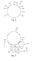
- FIG. 2 is simplified side view of a ball manufactured using the mold of FIG. 1 ;
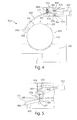
- FIG. 3 is a side view of the ball of FIG. 2 inserted into a ball holder
- FIG. 4 is a view, partially in section, of a selective deburring structure
- FIG. 5 is a partial cross sectional view showing a portion of the deburring structure
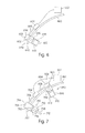
- FIG. 6 is a partial side view of a first embodiment of a portion of a deburring structure
- FIG. 7 is a partial side view of another embodiment of a portion of a deburring structure
- FIG. 8 is a top view of a ball holder plat
- FIG. 9 is a top view, partially in section, of an abrasive.
- FIG. 10 is a partial side view of another embodiment of a portion of a deburring structure.
- the present embodiments relate to structures used to deburr golf balls.
- the necessity of deburring golf balls is due to the methods typically used to mold golf balls.
- golf balls are made with an injection molding process.
- the injection molding process typically uses a mold that includes various discontinuities. Each discontinuity may cause a burr to be created on an external surface of the ball.
- FIG. 1 shows a molding step that represents the application of a final layer on a golf ball.
- the final molding step may be the addition of a cover layer, a top coat, or whatever final molding step a designer may deem desirable.
- the remaining layers of the ball internal to the final molded layer may collectively be called the interior layers and are numbered 102.
- layer 102 is a single layer or core.
- layer 102 may include a core, a medial layer, a mantle layer, other intermediate layers or inserts, either alone or in combination with one another.
- FIG. 1 shows the use of mold 130 to form the outermost layer.
- Mold 130 may be one of a variety of types of molds, depending on the material to be molded therein.
- mold 130 is shown as a standard injection mold.
- Mold 130 may include first mold portion 132 and second mold portion 134.
- First mold portion 132 and second mold portion 134 can be separated from one another to place items in mold 130 before molding occurs or to remove the formed material after molding.
- First mold portion 132 and second mold portion 134 form mold cavity 136 therein.
- Injection port 138 may be present, for example, at the top of mold cavity 136.
- Injection port 138 may be in fluid communication with reservoir 140 that contains material 101.
- material 101 may be a thermoplastic urethane, such as SURLYN. Material 101 is introduced into mold cavity 136 from reservoir 140 via injection port 138.
- vent holes may be incorporated into mold 130 to allow the air to evacuate.
- four vent holes are shown. Specifically, first vent hole 122, second vent hole 124, third vent hole 126, and fourth vent hole 128 are shown as extending at various locations between mold cavity 136 and the exterior of mold 130.
- the position and number of vent holes is exemplary and may be modified as desired by a person having ordinary skill in the art.
- FIG. 1 shows the use of first pin 146, second pin 148, third pin 150, and fourth pin 152.
- First pin 146, second pin 148, third pin 150, and fourth pin 152 are designed to be retractable within mold cavity 136.
- first pin 146 and fourth pin 152 can be retracted. As material 101 begins to further fill mold cavity 136, second pin 148 and third pin 150 can be retracted. This retraction after the partial hardening of material 101 allows interior layers 102 to remain centered within mold cavity 136 and for material 101 to evenly fill mold cavity 136. While not specifically shown and described, a similar method could be used to mold ball interior layers 102.
- pins 146, 148, 150, 152 are shown, and while they are shown protruding only from the sides of mold cavity 136, these features should not be seen as being limiting. In some embodiments, it may be desirable to place more or fewer pins in mold cavity 136. In other embodiments, it may be desirable to space the pins more evenly throughout mold cavity 136. Finally, it may be desirable to include pins on the top or bottom sides of mold cavity 136. A person having ordinary skill in the art will be able to modify the mold design to provide an appropriate molding environment based on the materials selected and the design characteristics desired.
- the pins are shown as still being in contact with inner layers 102, rather than having been retracted to be substantially flush with inner wall 145 of mold cavity 136.
- the pins are so positioned in FIG. 1 to aid understanding of their extended position.
- the pins would have been partially or fully retracted in order to allow the complete filling of cavity 136 with material 101.
- Mold 130 may also be heated or at room temperature, depending on the material to be injected to form the outermost layer. If mold 130 is heated, mold 130 may be allowed to cool. After mold 130 reaches room temperature or after the layers have been allowed to cure for an appropriate amount of time, the formed ball may be removed from mold 130, such as by separating first mold portion 132 from second mold portion 134.
- mold interior wall 145 may be designed to mold the outer surface of the ball. Accordingly, interior wall 145 may be patterned to allow for dimples and lands and other desirable markings to be molded into the cover of the ball.
- the precise configuration of the outer ball surface will depend on the desired ball characteristics. A person having ordinary skill in the art will be able to easily design interior wall 145 with desired characteristics in accordance with the ball's desired characteristics without undue experimentation.
- the pattern of dimples on the outside of the ball may be designed independently of the characteristics for the inner layers of the ball. In the present disclosure, the dimple pattern selected does not significantly affect the structures disclosed. Accordingly, interior wall 145 in the FIGS. is shown as being smooth, rather than showing the details of a pattern.
- FIG. 2 shows an exemplary ball 200 that is made with the process shown in FIG. 1 .
- FIG. 2 shows the existence of nine burrs on the outer surface 220 of ball 200.
- Outer surface 220 in many of the FIGS. is shown in simplified form as being a smooth surface.
- ball 200 would include various dimples and lands surrounding the dimples. The precise dimple pattern is not critical to the functioning of the present embodiments, so the dimple pattern has been eliminated from the FIGS. to improve understanding of the embodiments described herein.
- Each of the nine burrs shown in FIG. 2 corresponds generally in position to an element in mold 130 as shown and described in FIG. 1 .
- First burr 246, second burr 248, third burr 250, and fourth burr 252 correspond in position to the position of first pin 146, second pin 148, third pin 150, and fourth pin 152, respectively. Due to basic tolerance stack, differences in the shape of inner layers 102 and mold cavity wall 145 and other considerations, at each position where the respective pin meets mold cavity wall 145, a corresponding burr is likely to form on outer surface 220 of ball 200.
- fifth burr 222, sixth burr 224, seventh burr 226, and eighth burr 228 correspond in position to the position of first vent hole 122, second vent hole 124, third vent hole 126, and fourth vent hole 128, respectively.
- the vent holes are provided as openings to allow air to escape mold cavity 136. However, the vent holes are also likely to allow some degree of intrusion of material 101 into each vent hole during the molding process. This intrusion and other factors make a burr likely to form on outer surface 220 of ball 200 where it is adjacent each vent hole.
- Ninth burr 238 corresponds in position to the position of injection nozzle or port 138. Because of the discontinuity of inner mold wall 145 in the area of nozzle 138, and possibly due to the properties of material 101 that may not fully separate from nozzle 138, ninth burr 238 is likely to form on outer surface 220 of ball 200 in this area.
- FIG. 3 illustrates ball 200 positioned in ball holder 310.
- Ball holder 310 may be any sort of holder that is capable of locating a ball in a particular position.
- Ball holder 310 desirably defines a recess 312 in a first surface 314.
- Recess 312 may be designed to correspond generally in shape and size to any ball 200 that may be placed therein. According to USGA rules, a ball that conforms to the rules may not be smaller than 1.68 inches in diameter according to current rules and should be spherical and spherically symmetrical.
- a person having ordinary skill in the art can determine the diameter and depth of recess 312 necessary to accommodate ball 200 molded with the desired molding structure and method. If balls of varying diameters are to be used in connection with the presently described embodiments, either ball holders specifically designed for each diameter of ball may be selected or the central area 316 of ball holder 310 may be modified to allow provide for an adjustment structure to allow cavity 312 to have varying diameters. Recess 312 may be designed to have a surface 313 close to outer surface 220 of ball 200 as shown in FIG. 3 , but surface 313 of cavity 312 need not be close to outer surface 220 of ball 200 if it does not support ball 200.
- Ball grip 318 may be included in recess 312.
- Ball grip 318 may be any of a variety of materials that serve to prevent ball 200 from moving relative to ball holder 310, particularly when pressure is applied to ball 200, as will be described in greater detail below.
- grip 318 may be a rubberized strip that has adequate tack to tend to minimize slip, such as a rubberized material common to non-skid shoe soles.
- grip 318 could be an adhesive adequate to retain ball 200 in recess 312 while allowing ball 200 to be removed after the deburring process has been completed.
- grip 318 could be a mechanical clamp that mates with ball 200 to prevent movement.
- the only contact between ball 200 and holder 310 may be through grip 318.
- Rotator 304 may be incorporated as a part of ball holder 310.
- Rotator 304 may be any of a variety of structures capable of rotating ball holder surface 314.
- rotator 304 includes motor 306 and shaft 308.
- Motor 306 may desirably be a standard AC electric motor.
- Shaft 308 may be attached directly or through a transmission to the output shaft of motor 306 and may be attached directly or through a transmission to ball holder surface 314.
- Other configurations may also be used.
- rotator 304 may be a simple hand crank with an output shaft attached to ball holder surface 314.
- an engine, DC motor or other direct or indirect drive system may be used instead of the AC electric motor.
- the rotator may be configured to be able to receive and be directed by electrical controller 307 located close to or remotely from rotator 304.
- Electrical controller 307 may be able to remotely control, for example, whether motor 306 is on or off and the speed at which shaft 308 and ball holder surface 314 rotate. If a transmission is used at either end of shaft 308, electrical controller 307 may also govern the gear reduction used, if multiple gears are possible.
- FIG. 4 an overall configuration of various elements that may be used in deburring ball 200 is shown.
- the basic elements are holder 310 and arm 460. These two elements interact with ball 200 to remove burrs 201 from outer surface 220 of ball 200.
- Arm 460 is adjustable. The relative position of arm 460 relative to ball 200 and holder 310 is determined by the actions of positioners 462. A variety of structures can be incorporated into positioners 462. In the embodiment shown in FIG. 4 , positioners 462 include a first cam 464, a second cam 466, and a gear 468.
- First cam 464 is positioned adjacent first side 470 of arm 460.
- Second cam 466 is positioned adjacent second side 472 of arm 460.
- First cam 464 is rotatable and may include first central section 474 and first cam surface 476. When first cam 464 rotates, first cam surface 476 comes into contact with first side 470 of adjustable arm 460. Contact between first cam surface 476 and adjustable arm 460 changes the angular position of adjustable arm 460 relative to holder 310 and ball 200.
- Second cam 466 is also rotatable and may include second central portion 478 and second cam surface 480. When second cam 466 rotates, second cam surface 480 comes into contact with second side 472 of adjustable arm 460.
- First cam 464 and second cam 466 can be used independently of one another or may be used cooperatively to further stabilize adjustable arm 460 in a desired angular position.
- First cam 464 and second cam 466 may be positioned manually or may be positioned electronically. In some embodiments, first cam 464 and second cam 466 may be electronically controlled by electronic control unit 307.
- Gear 468 may be used to change the effective length of arm 460 relative to holder 310 and ball 200.
- Gear 468 is shown in greater detail in FIG. 5 .
- Gear 468 includes gear teeth 578.
- Arm 460 includes mating gear teeth 580 shown as being positioned on second side 472 of arm 460. While gear 468 and its related parts are shown as being on second side 472 of arm 460, gear 468 and its related parts and mating gear teeth 580 could instead be positioned on first side 470 of arm 460.
- Gear teeth 578 and mating gear teeth 580 function to change the effective length of arm 460. In the configuration shown in FIGS.
- gear 468 may be manually rotated by a knob or crank (not shown). In an alternative embodiment, rotation of gear 468 may be electrically controlled, such as by electric motor 579, which may also be connected to electric controller 307 to control the position of gear 468 and arm 460.
- gear 468 functions as a fulcrum in combination with first cam 464 and second cam 466. In such an embodiment, it may be desirable to allow gear 468 to move upward and downward to permit a greater range of motion of arm 460 relative to holder 310.
- Pin 582 may be attached to gear 468 and may extend on the opposite side 470 of arm 460 from gear 468.
- Attachment structure 584 that attaches pin 582 to gear 468 may be adjustable to correct for tolerance stack between arm 460 and gear 468 or to allow for removal of arm 460 for replacement. Attachment structure 584 is illustrated in FIGS. 4 and 5 as being a fixed arm. However, in some embodiments, attachment structure 584 could be a spring or other structure. In many embodiments, it is desirable that attachment structure 584 be designed to firmly press gear teeth 578 and mating gear teeth 580 into contact with one another.
- gear 468 may be configured to allow it to ride in slot 586.
- Slot 586 may be any appropriate length that allows the desired range of motion.
- Gear 468 may be manually adjustable by a manual slide and lock (not shown).
- the height of gear 468 in slot 586 may be governed by an electric motor, for example, or other electronic control, which may be connected to electronic control unit 307.
- pin 582 and gear 468 may be fixed in place and arm 460 guided between them.
- Pin 582 may be a round pin as shown or may alternatively be a flat surface.
- the precise configuration of the pin and gear may be modified in various ways known to a person of ordinary skill in the art while still providing sufficient stability to the gear and pin system to allow it to function as a fulcrum.
- Abrasive 690 is provided on arm 460.
- Abrasive 690 is shown in simplified form in FIG. 4 and in more detail in FIG. 6 .
- Abrasive 690 is shown in FIGS. 4 and 6 as being positioned near free end 692 of arm 460. However, abrasive 690 need not be so positioned.
- Abrasive 690 may be positioned at any desirable position along arm 460.
- Arm 460 may, in some embodiments, not include a free end, but instead may extend in a closed curve around ball 200.
- Abrasive 690 includes a variety of elements.
- Abrasive 690 includes a casing 694, including divider 696, reciprocating finger 698, plunger 602, hydraulic fluid input 604, and fluid transmission device 606.
- hydraulic fluid input 604 may be an air compressor.
- input or compressor 604 When it is desired to move plunger 602 downward towards divider 696, input or compressor 604 is actuated. Fluid, such as air, is sent through tube or fluid transmission device 606 into cavity 608 adjacent plunger 602. The introduction of air or other hydraulic fluid into cavity 608 moves plunger 602 towards divider 696 and moves reciprocating finger 698 outward from open end 610 of casing 694.
- Reciprocating finger 698 includes at least one abrasive surface, such as abrasive surface 612.
- Abrasive surface 612 may be made from a variety of materials, but may be selected in cooperation with the material from which one or more burrs 201 on ball 200 are formed. For example, the desirable hardness of abrasive surface 612 may differ depending on the material forming the burr.
- Abrasive surface 612 may be thin, such as if abrasive surface 612 is formed of sandpaper over a support. Alternatively, abrasive surface 612 may be coextensive with finger 698, such as if a piece of pumice, for example, were to be used as abrasive surface 612.
- the entirety of finger 698 may be made of the abrasive material.
- the extent of the projection of finger 698 towards ball 200 may be calculated based on the amount of finger 698 that has become worn.
- abrasive surface 612 is thin, replacement of abrasive surface 612 may be more frequent, and a calculation, estimate, or sensor reading of the degree of deterioration of abrasive surface 612 may be less important.
- compressor or input 604 can again be actuated, but the flow reversed. In such an instance, air or other fluid would be pumped away from cavity 608 through tube 606, thereby creating a vacuum in cavity 608. Such a vacuum causes plunger 602 to move away from divider 696, thereby retracting finger 698 into casing 694.
- the actuation of the hydraulic input 604 may be done manually, such as with a user pressing a button or actuating a switch (not shown). Alternatively, the actuation of hydraulic input 604 may be performed electronically, such as through electric control unit 307. If actuation is done electronically, a sensor to detect any degree of deterioration of abrasive surface 612 may be included in order to allow electric control unit 307 to more precisely control hydraulic input 604 to properly position finger 698 and abrasive surface 612 relative to holder 310, ball 200, and burrs 201.
- FIG. 7 shows the use of a first abrasive 790 and a second abrasive 890 on the same arm 460. As shown in FIG. 7 , multiple abrasives may be used on the same arm 460, and the abrasives may be independently controlled.
- FIG. 7 shows a single hydraulic input 704 capable of sending hydraulic fluid through first tube or transmission device 706 and second tube or transmission device 806 independently.
- independent valving (not shown) as may be commonly understood by persons having ordinary skill in the art.
- the valving, as the input may be controlled either manually through, for example, a lever (not shown) or electronically through, for example, electric control unit 307.
- first plunger 702 or second plunger 802 When it is desired to move first plunger 702 or second plunger 802 downward towards first divider 796 or second divider 896, input or compressor 704 is actuated. Fluid, such as air, is sent through first tube or fluid transmission device 706 into first cavity 708 adjacent first plunger 702. Fluid, such as air, may also be sent through second tube or fluid transmission device 806 into second cavity 808 adjacent second plunger 802. The introduction of air or other hydraulic fluid into first cavity 708 moves first plunger 702 towards first divider 796 and moves first reciprocating finger 798 outward from first open end 710 of first casing 794.
- Fluid such as air
- First reciprocating finger 798 includes first abrasive surface 712 and second reciprocating finger 898 includes second abrasive surface 812. As shown in FIG. 7 , it may be desirable in some embodiments for first abrasive surface 712 and second abrasive surface 812 to have different shapes and sizes. It may also be desirable in some embodiments for first abrasive surface 712 and second abrasive surface 812 to be made from different materials. Otherwise, the properties of first abrasive surface 712 and second abrasive surface 812 may be the same as those described in connection with abrasive surface 612.
- each of the elements described may be secured to a single casing.
- the use of a single casing to enclose all the elements described may be desirable, as the process of deburring can create particulate matter that may be forcefully thrown from the area of the ball.
- the use of a single casing attached directly or indirectly to each element may be unnecessary, and instead, the elements may simply be placed in position relative to one another.
- a protective screen to deflect any thrown particulate matter may be positioned between a user and the structure described.
- Ball 200 is placed in holder 310.
- Ball 200 may be desirably positioned so that any burrs 201 thereon may be removed with the present process.
- the ball may be marked to enable a user or machine to substantially precisely position ball 200 in holder 310 so that burrs 201 appear in predictable locations.
- the burrs 201 appear on outer surface 220 of ball 200 in a generally predictable pattern, as burrs 201 are created generally by known and designed discontinuities in mold 130 (shown in FIG. 1 ).
- one or more sensors may be incorporated into the system to map the burrs on the ball and to designate the areas for deburring.
- Arm 460 is then placed into proper position.
- the effective length of arm 460 may be adjusted by rotating gear 468 either clockwise or counter-clockwise.
- the effective angular position of arm 460 may be adjusted by rotating first cam 464, second cam 466, or both.
- the abrasive surface is placed in effective position by moving reciprocating finger 698 so that abrasive surface 612 is in operative position near one or more burrs.
- Holder 310 is then rotated.
- the rotation of holder 310 causes ball 200 to rotate.
- the rotation of ball 200 causes abrasive surface 612 to contact burrs 201 and possibly outer surface 220 of ball 200 in a ring around ball 200.
- arm 460 may be repositioned to remove another at least one burr 201.
- mold 130 may be designed to place as many burrs as possible in such a manner that they can be removed in a single abrasive pass, thereby minimizing the number of abrasive passes necessary and minimizing harm to the outermost cover or surface layer of ball 200.
- FIGS. 8-10 An alternative embodiment is shown in FIGS. 8-10 .
- Such a structure is shown in FIGS. 8-10 .
- FIG. 8 shows ball holder plate 900.
- Ball holder plate 900 may also include axis 920.
- Ball holder plate 900 may be configured to be rotatable about axis 920.
- Ball holder plate 900 may include a fixed axis 920 with a driving rotator located outwardly from axis 920 or rotating motion may be generated from a rotator located at axis 920.
- Ball holder plate 900 may include a plurality of ball holder recesses. These may include first ball holder recess 902, second ball holder recess 904, third ball holder recess 906, fourth ball holder recess 908, fifth ball holder recess 910, sixth ball holder recess 912, seventh ball holder recess 914, eighth ball holder recess 916, and ninth ball holder recess 918.
- a ball (not shown) may be placed with conventional apparatus (not shown) into first ball holder recess 902. The ball may be placed in first ball holder recess 902 to be positioned in the same relative position as ball 200 was shown as being placed in ball holder 310.
- a sensor 901 see FIG.
- first ball holder recess 902 may be used to verify the orientation of a ball placed in first ball holder recess 902, to ensure that each burr on the ball is exposed and is available to be removed.
- the mechanism used to insert the ball may be any of a variety of conventional ball placement apparati, and is labeled generally as 950.
- the insertion of an exemplary ball into first ball holder recess 902 is shown by an arrow.
- each ball holder recess may take a variety of positions. In the embodiment shown, because there are nine recesses, there are nine corresponding positions, and the precise configuration is exemplary only.
- a ball may be placed into first ball holder recess 902 when recess 902 is in position 903 adjacent inserter 950. Plate 920 then may be rotated, as is shown by the arrows positioned in a clockwise manner on plate 920. The use of a clockwise rotation is exemplary, and a counterclockwise rotation may be used where desired.
- Recess 902 may rotate from insertion position 903 into a first abrading position 905 adjacent first abrader 960, the structure and function of which will be described in greater detail below.
- First abrader 960 may perform a first abrading step on the ball. After the completion of first abrading step by first abrader 960, the ball in recess 902 may rotate from first abrading position 905 into second abrading position 907 adjacent second abrader 962 to undergo a second abrading step. After the completion of first abrading step by first abrader 960, recess 902 may rotate from first abrading position 905 into second abrading position 907 adjacent second abrader 962 to cause the ball to undergo a second abrading step.
- recess 902 may rotate from second abrading position 907 into third abrading position 909 adjacent third abrader 964 to cause the ball to undergo a third abrading step.
- the ball may be further rotated into fourth abrading position 911 adjacent fourth abrader 966, fifth abrading position 913 adjacent fifth abrader 968, and sixth abrading position 915 adjacent sixth abrader 970.
- the ball may undergo a correspondingly numbered abrading step in each corresponding position.
- Each abrader may have the same configuration. Accordingly, when a structure is referred to as abrader 960, it is understood that such an abrader could take any position around ball holder plate 920.
- Removal recess position 917 may be adjacent any conventional ball removal apparatus, and that apparatus is numbered generally as 980.
- the removal of the ball from ball holder plate 900 at removal recess position 917 is shown generally by an arrow.
- ball holder recess 902 may move into a rest position 919. Rest position 919 between removal position 917 and insertion position 903 may be optionally used where it is deemed desirable to prevent interference between inserter 950 and remover 970, to accommodate other ball transport equipment, or for any other reason.
- an alignment recess position may be incorporated between insertion recess position 903 and first abrasion position 905. Such an alignment recess position may be used to verify the position of the ball within the recess, rather than incorporating such an alignment function into the insertion position. If desired, an alignment recess position may be incorporated between two adjacent treatment positions to ensure that the ball has not moved during treatment at the prior recess position.
- the selection of a particular size and number of recesses in ball holder plate 900 may vary depending on the manufacture of the balls to be treated. As noted earlier, the number of burrs on any ball may be dependent on the number of runners and gates incorporated into the mold in which the ball is manufactured. The number and size of the gates used may vary from ball to ball, depending on the material used to make the ball cover, the thickness of the cover, the temperature at which the ball is molded, and many other factors.
- the apparatus used may be configured to be modular. For example, if only two abrasion positions were necessary, the different ball holder plate may be configured to have only 4 recesses and corresponding positions, namely, an insertion position 903, two abrasion positions 905 and 907, and a removal recess 917.
- a first ball insertion apparatus 950 may be positioned adjacent insertion position 903.
- a ball may be inserted at insertion position 903 and passed through, for example, two treatment positions, such as a first treatment position 905 and a second treatment position 907.
- a ball removal apparatus 980 may be positioned adjacent position 909, and 909 may become a removal position.
- a second ball insertion apparatus 950 may also be positioned adjacent ball holder position 911, so that ball holder position 911 may become an insertion position.
- a ball inserted at ball holder position 911 may be rotated through two treatment positions, such as a first treatment position 913 and second treatment position 915, and the ball may be removed at ball removal position 917 by ball removal apparatus 980.
- a respective ball may thus be simultaneously inserted at each respective insertion position 903 and 911.
- Each ball would be simultaneously treated respectively at two ball holder recess positions, namely positions 905 and 907 and positions 913 and 915, respectively.
- Each respective ball may then be simultaneously removed at each respective removal position 909 and 917. In such a configuration, two balls could be treated at the same time.
- the ball may be inserted into ball holder plate 900 at insertion position 903 and be extracted at removal position 917 and receive the designated number of treatments at corresponding number of positions along the plate 900. In any remaining recesses, the ball may simply remain in the recess without any activity. For example, if only four abrasion treatments were necessary, only four abraders may be used adjacent four corresponding ball positions around ball holder plate 900. Other ball positions would not have any equipment adjacent thereto and the ball would remain untreated in those positions.
- a structure similar to those disclosed above may be incorporated at each of the abrasion ball positions as an abrader 960.
- an arm 460 is positioned in a designated position at each abrasion or treatment position of ball holder plate 900.
- each arm 460 may be manually moved to a designated position or the position of each arm may be controlled by an electronic control unit 307.
- a ball 200 may be rotated into a treatment position, such as first treatment position 905.
- First treatment arm 460 and first abrasive 690 may then be moved into a first effective position to effectively remove one or more burrs 201 as described in greater detail above.
- first treatment arm 460 and first abrasive 690 may be moved away from exemplary ball 200 in first treatment position 903.
- Ball recess plate 900 may then rotate and exemplary ball 200 may then be positioned in second treatment or abrasion position 905.
- second abrasion position 905 another first treatment arm 460 and another first abrasive 690 may be present.
- This another first treatment arm 460 and this another first abrasive 690 may then be moved into a second effective position to effectively remove another burr 201 from ball 200.
- each treatment position on ball recess plate 900 it may receive a desired series of treatments from each first treatment arm 460 and each first abrasive at each treatment position.
- FIG. 9 shows a first abrasive 1000.
- First abrasive 1000 may have a number of components.
- First abrasive 1000 may include a first abrasive surface 1002.
- First abrasive surface 1002 may, in some embodiments, be formed of a sheet-like abrasive.
- first abrasive surface 1002 may be a sheet of sandpaper.
- First abrasive surface 1002 may be a continuous loop 1004 of abrasive. Continuous loop 1004 may be of sufficient length to extend around a series of rotatable pulleys. In the embodiment shown in FIG.
- the rotatable pulleys include first rotatable pulley 1006, second rotatable pulley 1008, third rotatable pulley 1010, and fourth rotatable pulley 1012. While four rotatable pulleys are shown, another number of rotatable pulleys may be deemed desirable by a person having ordinary skill in the art. The use of four rotatable pulleys in FIGS. 9 and 10 is merely exemplary. In some embodiments, one of the rotatable pulleys may be a drive pulley and the remaining pulleys may simply rotate about an axis. In other embodiments, each pulley may be a drive pulley.
- first rotatable pulley 1006 may be a drive pulley.
- First rotatable pulley 1006 may be driven by a drive motor 1014 shown generally connected to first rotatable pulley 1006.
- drive motor 1014 may be drive first rotatable pulley 1006 by rotating first rotatable pulley 1006 by its axis 1016.
- first rotatable pulley 1006 may be rotated other than by its axis, such as by a set of gear teeth (not shown), a magnetic drive, or any other drive system that may be deemed desirable by a person having ordinary skill in the art.
- Drive motor 1014 may be manually actuated or control of drive motor 1014 may be controlled by electronic control unit 307.
- continuous loop 1004 and the rotatable pulleys 1006, 1008, 1010, and 1012 may be designed in a manner so that loop 1004 fits snugly against each pulley in operation. This feature may be accomplished with a variety of structures.
- loop 1004 may be made from a material that has some resilience. When such a loop 1004 is placed around first pulley 1006, second pulley 1008, third pulley 1010, and fourth pulley 1012, in some embodiments, the loop 1004 may be slightly loose, as it will be deformed in use, as will be described in greater detail below.
- the loop may have sufficient resilience and be of such a shape and size that it may fit snugly around first pulley 1006, second pulley 1008, third pulley 1010, and fourth pulley 1012.
- loop 1004 may be designed to be of a fixed length and have minimal resilience. In such an embodiment, loop 1004 may be slightly loose around first pulley 1006, second pulley 1008, third pulley 1010, and fourth pulley 1012 when not in use and fit more snugly while in use, as will be described in greater detail below.
- a lock or guide may be incorporated with or adjacent at least one of the pulleys to reduce the risk of loop 1004 slipping off or otherwise becoming detached from the pulley system.
- loop 1004 is shown in a position where it is not in use.
- a case 1018 may surround much of the pulley and loop structure.
- case 1018 is rectangular. However, other shapes may be used.
- case 1018 may be made at least partially of a resin or plastic.
- case 1018 may be made of metal.
- it may be desirable to use a substantially closed structure.
- it may be desirable to use a substantially open structure.
- loop 1004 it may be within case 1018 while in its rest position.
- case 1018 may have a removable top to allow for servicing or replacement of any of the interior parts.
- case 1018 may include at least one aperture 1020 along one side 1022.
- a purpose for aperture 1020 may be to allow loop 1004 to project outwardly from case 1018.
- a reciprocating finger 1024 may be reciprocally positioned within case 1018.
- Reciprocating finger 1024 may be coupled to a reciprocating drive 1026.
- Reciprocating drive 1026 may be any system that is capable of moving reciprocating finger 1024 in and out of case 1018 through aperture 1020.
- reciprocating drive 1026 may be a hydraulic pump that moves reciprocating finger 1024 in a manner similar to that described for reciprocating finger 698 earlier, and this description is not repeated here, such as via an air compressor or other fluid input.
- reciprocating drive 1026 may be manually actuated or may be further connected to electronic control unit 307, which may control its motion.
- reciprocating finger 1024 moves outwardly from case 1018 (shown as downwardly in FIG. 9 ), it engages loop 1004.
- the outward movement of reciprocating finger 1024 causes the tightening of loop 1004 around first pulley 1006, second pulley 1008, third pulley 1010, and fourth pulley 1012.
- loop 1004 may rotate around first pulley 1006, second pulley 1008, third pulley 1010, and fourth pulley 1012 and against engaging surface 1028 of reciprocating finger 1024.
- Engaging surface 1028 may be any desired size and shape, and the size and shape of engaging surface 1028 shown in FIG. 9 is merely exemplary. Also as shown in FIG.
- reciprocating finger 1024 may include first guide 1030 and second guide 1032.
- First guide 1030 and second guide 1032 may serve as guides for loop 1004 during the rotation of loop 1004.
- the use of guides such as first guide 1030 and second guide 1032 may be desirable in some embodiments and eliminated in other embodiments.
- FIG. 9 may be placed adjacent the structure shown in FIG. 8 to deburr the ball.
- An abrader 960 is shown in FIG. 10 .
- a ball, such as ball 200 is placed in a ball holder recess, such as ball holder recess 904.
- Casing 1018 is moved into a desired position.
- casing 1018 is slidably attached to a C-shaped projection or channel 1100. Any desired structure may be used for such a slidable attachment.
- casing 1018 may include one or more fingers (not shown) that project into a channel or around a projection 1100.
- a corresponding projection and channel regardless of which element the projection and channel appear on cause the casing 1018 and projection 1100 to include a camming function that causes the rotation of the casing 1018 relative to the projection 1100.
- the relative position of casing 1018 and projection or channel 1100 may be controlled by any desired system.
- a hydraulic arm 1102 may be used. When the lower arm 1104 projects to the outwardly position shown in FIG. 10 , the interaction of the finger and channel 1100 may function to move the casing to a generally horizontal position. When hydraulic arm 1104 moves more inwardly, casing 1018 may be forced to move along channel 1100 to assume a different angular position.
- casing 1018 may be positioned in a variety of angular positions relative to ball 200.
- the projection of lower arm 1104 from arm 1102 may be controlled by a hydraulic pump 1106.
- Hydraulic pump 1106 may be controlled manually or may be connected to electronic control unit 307.
- the use of a hydraulic arm and pump are merely exemplary.
- Other mechanisms well-known to people having ordinary skill in the art may be used to move casing 1018 to various positions. Such mechanisms may be controlled manually or by electronic control unit 307.
- an optional sensor 901 may be used to ensure that ball 200 is properly positioned.
- Sensor 901 may alternatively be designed to sense the position of any burrs 201 on ball 200. Information on the position of ball 200 or burrs 201 may be transmitted to electronic control unit 307 or may be transmitted directly to a user via an interface. Once ball 200 or burrs 201 are properly positioned, the deburring may take place.
- the use of a sensor 901 may be optional and a sensing step may be performed at each position, may be done only once, or may not be done at all. Once the optional sensing step is performed, a deburring step may occur.
- casing 1018 may be moved along channel or projection 1100 to an appropriate location.
- Reciprocating drive 1026 may then be actuated to cause finger 1024 and abrasive 1000 to project through aperture 1020 to be positioned at a burr 201.
- Rotator 304 may then be actuated to rotate ball 200 and drive motor 1014 may be actuated to rotate loop 1004.
- Abrasive 1000 may thereby be brought into contact with a corresponding burr 201 for a predetermined period of time. After the predetermined period of time has passed, the rotator 304 and drive motor 1014 may be deactivated.
- Ball holder plate 900 may then be rotated to bring another ball 200 into position 904 for removal of the same burr 201 at that station.
- each station may correspond with a ball recess position and may include a casing and channel system as shown in FIG. 10 .
- Each station may position casing 1018 in a different angular position along channel 1100 to remove a different burr 201 from ball 200. In such a manner, each station would represent one possible position to which finger 1024 may be moved as was the case in the previous embodiments.
- casing 1018 may assume a plurality of positions, similar to the arm 460 as described in previous embodiments.
- casing 1018 may be moved to a desired location, finger 1024 may be actuated to extend to be positioned adjacent burr 201, and ball 200 may be rotated for a designated period of time. Finger 1024 may then be retracted and casing 1018 may be moved through the camming action between the channel and finger to an alternate position. The same structure and method can then be used to remove another burr or set of burrs from a ball.
- casing 1018 may be considered to be the same as arm 460.
- Casing 1018 may be considered to be an adjustable arm capable of moving relative to ball holder recesses, such as ball holder recess 904 as shown in FIG. 10 .
- Finger 1024 may be considered to be similarly attached to and capable of reciprocating relative to arm 1018.
- arm 1018 When arm 1018 is moved to a desired position, it may be considered to have an effective length and angular position relative to the channel or finger 1100 and relative to ball holder recess 904.
- Each casing may be considered a separate arm.
Landscapes
- Health & Medical Sciences (AREA)
- General Health & Medical Sciences (AREA)
- Physical Education & Sports Medicine (AREA)
- Engineering & Computer Science (AREA)
- Mechanical Engineering (AREA)
- Physics & Mathematics (AREA)
- Thermal Sciences (AREA)
- Grinding And Polishing Of Tertiary Curved Surfaces And Surfaces With Complex Shapes (AREA)
- Finish Polishing, Edge Sharpening, And Grinding By Specific Grinding Devices (AREA)
- Moulds For Moulding Plastics Or The Like (AREA)
Abstract
Description
- The present disclosure relates generally to a structure used to deburr a golf ball outer surface. More specifically, the present disclosure relates to a structure that allows for selective removal of burrs on a golf ball.
- Many golf balls are made of multiple layers. Many of these golf balls are manufactured using an injection molding technique. While much of the interior surface of a typical golf ball mold is smooth, various surface discontinuities are created on the product within common molding techniques.
- In many instances, golf balls are molded using an injection mold. When an injection mold is used, various features are common. First, there is typically an opening for an injection nozzle to be inserted into the mold cavity. Next, there are frequently one or more vent holes to vent air when the mold is being filled with resin or other material. Finally, there may be holes for pins that are inserted to stabilize an intermediate layer while it is surrounded with another material. Each of these openings in the mold creates a discontinuity in the mold surface. Each discontinuous area may create a discontinuity or burr on the molded ball.
- Discontinuities and burrs on the ball are generally undesirable. The aerodynamic properties of the ball are typically important to a golfer. Any area of discontinuity may tend to alter the aerodynamic properties of the ball and create an unsatisfactory flight path. Accordingly, there have been systems and structures used to deburr the balls after molding.
- In some prior systems, the molded ball, possibly along with other balls, has been placed into a bin and surrounded by abrasive articles, such as sandpaper, pumice, or the like. The bin is then agitated and the ball is removed. In such a system, there is an inability to precisely control the degree of abrasion on the ball, and the ball's surface may be inconsistently abraded, creating a different discontinuity.
- In other prior systems, the ball may be placed within a grinder and rotated or agitated while an abrasive surface evenly abrades the entirety of the ball surface. Such a system also abrades the surface of the ball where no abrasion needs to be applied. Accordingly, while such a system may remove the burrs, it also tends to damage other areas of the ball's surface.
- What is desirable is a structure and method that may be used to selectively abrade a ball's surface in areas where burrs exist, while avoiding areas that lack burrs. Such a system may tend to effectively remove burrs while also minimizing damage to other areas of the ball.
- In one embodiment, a deburring structure for removing at least one burr from a ball is provided. A ball holder is provided. An adjustable arm is capable of moving relative to the ball holder. A first finger is attached to the arm and is capable of reciprocating relative to the arm. The first finger includes an abrasive surface. An electronic control can be used to govern the movement of the various parts with respect to one another.
- In another embodiment, a structure for deburring a ball is provided. A ball holder is provided. An arm is provided with an effective length and an effective angular position relative to the ball holder. A first cam is positioned on a first side of the arm. The first cam is capable of moving the arm to change its effective angular position relative to the ball holder. A second cam may be positioned on a second side of the arm and may also be capable of moving the arm to change its effective angular position relative to the ball holder. A gear may be positioned on one side of the arm to change the effective length of the arm relative to the ball holder. One or more fingers may be reciprocally positioned on the arm. An electronic control can be used to govern the movement of the various parts relative to one another.
- Other systems, methods, features and advantages of the embodiments will be, or will become, apparent to one of ordinary skill in the art upon examination of the following figures and detailed description. It is intended that all such additional systems, methods, features and advantages be included within this description and this summary, be within the scope of the disclosure, and be protected by the following claims.
- The invention can be better understood with reference to the following drawings and description. The components in the figures are not necessarily to scale, emphasis instead being placed upon illustrating the principles of the invention. Moreover, in the figures, like reference numerals designate corresponding parts throughout the different views.
-
FIG. 1 is cross sectional view of a ball being molded in one embodiment of an injection mold; -
FIG. 2 is simplified side view of a ball manufactured using the mold ofFIG. 1 ; -
FIG. 3 is a side view of the ball ofFIG. 2 inserted into a ball holder; -
FIG. 4 is a view, partially in section, of a selective deburring structure; -
FIG. 5 is a partial cross sectional view showing a portion of the deburring structure; -
FIG. 6 is a partial side view of a first embodiment of a portion of a deburring structure; -
FIG. 7 is a partial side view of another embodiment of a portion of a deburring structure; -
FIG. 8 is a top view of a ball holder plat; -
FIG. 9 is a top view, partially in section, of an abrasive; and -
FIG. 10 is a partial side view of another embodiment of a portion of a deburring structure. - The present embodiments relate to structures used to deburr golf balls. The necessity of deburring golf balls is due to the methods typically used to mold golf balls. Frequently, golf balls are made with an injection molding process. The injection molding process typically uses a mold that includes various discontinuities. Each discontinuity may cause a burr to be created on an external surface of the ball.
-
FIG. 1 shows a molding step that represents the application of a final layer on a golf ball. The final molding step may be the addition of a cover layer, a top coat, or whatever final molding step a designer may deem desirable. The remaining layers of the ball internal to the final molded layer may collectively be called the interior layers and are numbered 102. In some embodiments,layer 102 is a single layer or core. In other embodiments,layer 102 may include a core, a medial layer, a mantle layer, other intermediate layers or inserts, either alone or in combination with one another. -
FIG. 1 shows the use ofmold 130 to form the outermost layer.Mold 130 may be one of a variety of types of molds, depending on the material to be molded therein. InFIG. 1 ,mold 130 is shown as a standard injection mold.Mold 130 may includefirst mold portion 132 andsecond mold portion 134.First mold portion 132 andsecond mold portion 134 can be separated from one another to place items inmold 130 before molding occurs or to remove the formed material after molding.First mold portion 132 andsecond mold portion 134form mold cavity 136 therein.Injection port 138 may be present, for example, at the top ofmold cavity 136.Injection port 138 may be in fluid communication withreservoir 140 that containsmaterial 101. In some embodiments,material 101 may be a thermoplastic urethane, such as SURLYN.Material 101 is introduced intomold cavity 136 fromreservoir 140 viainjection port 138. - As
material 101 is injected intomold cavity 136, air must be evacuated frommold cavity 136. Accordingly, vent holes may be incorporated intomold 130 to allow the air to evacuate. In the embodiment shown inFIG. 1 , four vent holes are shown. Specifically,first vent hole 122,second vent hole 124,third vent hole 126, andfourth vent hole 128 are shown as extending at various locations betweenmold cavity 136 and the exterior ofmold 130. The position and number of vent holes is exemplary and may be modified as desired by a person having ordinary skill in the art. - As shown in
FIG. 1 , one option for properly positioninginterior layers 102 inmold cavity 136 is to supportinterior layers 102 with a plurality of pins.FIG. 1 shows the use of first pin 146,second pin 148,third pin 150, andfourth pin 152. First pin 146,second pin 148,third pin 150, andfourth pin 152 are designed to be retractable withinmold cavity 136. Asmaterial 101 is injected intomold cavity 136, it fillsmold cavity 136. As it begins to harden, it becomes capable of supportinginterior layers 102 withinmold cavity 136. Asmaterial 101 begins to harden, first pin 146 andfourth pin 152 can be retracted. Asmaterial 101 begins to further fillmold cavity 136,second pin 148 andthird pin 150 can be retracted. This retraction after the partial hardening ofmaterial 101 allowsinterior layers 102 to remain centered withinmold cavity 136 and formaterial 101 to evenly fillmold cavity 136. While not specifically shown and described, a similar method could be used to mold ball interior layers 102. - While four
pins mold cavity 136, these features should not be seen as being limiting. In some embodiments, it may be desirable to place more or fewer pins inmold cavity 136. In other embodiments, it may be desirable to space the pins more evenly throughoutmold cavity 136. Finally, it may be desirable to include pins on the top or bottom sides ofmold cavity 136. A person having ordinary skill in the art will be able to modify the mold design to provide an appropriate molding environment based on the materials selected and the design characteristics desired. - In
FIG. 1 , the pins are shown as still being in contact withinner layers 102, rather than having been retracted to be substantially flush withinner wall 145 ofmold cavity 136. The pins are so positioned inFIG. 1 to aid understanding of their extended position. In a commercial embodiment, when the material 101 had completely filledmold cavity 136 to this extent, it is likely that the pins would have been partially or fully retracted in order to allow the complete filling ofcavity 136 withmaterial 101. -
Mold 130 may also be heated or at room temperature, depending on the material to be injected to form the outermost layer. Ifmold 130 is heated,mold 130 may be allowed to cool. Aftermold 130 reaches room temperature or after the layers have been allowed to cure for an appropriate amount of time, the formed ball may be removed frommold 130, such as by separatingfirst mold portion 132 fromsecond mold portion 134. - The configuration of mold
interior wall 145 may be designed to mold the outer surface of the ball. Accordingly,interior wall 145 may be patterned to allow for dimples and lands and other desirable markings to be molded into the cover of the ball. The precise configuration of the outer ball surface will depend on the desired ball characteristics. A person having ordinary skill in the art will be able to easily designinterior wall 145 with desired characteristics in accordance with the ball's desired characteristics without undue experimentation. The pattern of dimples on the outside of the ball may be designed independently of the characteristics for the inner layers of the ball. In the present disclosure, the dimple pattern selected does not significantly affect the structures disclosed. Accordingly,interior wall 145 in the FIGS. is shown as being smooth, rather than showing the details of a pattern. -
FIG. 2 shows anexemplary ball 200 that is made with the process shown inFIG. 1 .FIG. 2 shows the existence of nine burrs on theouter surface 220 ofball 200.Outer surface 220 in many of the FIGS. is shown in simplified form as being a smooth surface. In a commercial embodiment,ball 200 would include various dimples and lands surrounding the dimples. The precise dimple pattern is not critical to the functioning of the present embodiments, so the dimple pattern has been eliminated from the FIGS. to improve understanding of the embodiments described herein. - Each of the nine burrs shown in
FIG. 2 corresponds generally in position to an element inmold 130 as shown and described inFIG. 1 . First burr 246,second burr 248,third burr 250, andfourth burr 252 correspond in position to the position of first pin 146,second pin 148,third pin 150, andfourth pin 152, respectively. Due to basic tolerance stack, differences in the shape ofinner layers 102 andmold cavity wall 145 and other considerations, at each position where the respective pin meetsmold cavity wall 145, a corresponding burr is likely to form onouter surface 220 ofball 200. -
Fifth burr 222,sixth burr 224,seventh burr 226, andeighth burr 228 correspond in position to the position offirst vent hole 122,second vent hole 124,third vent hole 126, andfourth vent hole 128, respectively. The vent holes are provided as openings to allow air to escapemold cavity 136. However, the vent holes are also likely to allow some degree of intrusion ofmaterial 101 into each vent hole during the molding process. This intrusion and other factors make a burr likely to form onouter surface 220 ofball 200 where it is adjacent each vent hole. -
Ninth burr 238 corresponds in position to the position of injection nozzle orport 138. Because of the discontinuity ofinner mold wall 145 in the area ofnozzle 138, and possibly due to the properties ofmaterial 101 that may not fully separate fromnozzle 138,ninth burr 238 is likely to form onouter surface 220 ofball 200 in this area. - The positioning of the various mold elements and the corresponding burrs has been simplified in the FIGS. and in the description. In a commercial embodiment, it is unnecessary and may be undesirable for all the pins, vent holes, and injection ports to align along a single plane in
mold 130. A person having ordinary skill in the art is likely to design a mold where the pins, vent holes, and port are spaced from one another aroundmold 130. However, regardless of the specific position of each of these elements, a burr is likely to form in each area of discontinuity in a mold. Other elements in the mold may also create areas of discontinuity but have not been illustrated. The illustration of these elements and the corresponding burrs aligned on a single plane is merely for ease of illustration and understanding and the present embodiments should not be considered as being limited to situations where the burrs are so aligned. -
FIG. 3 illustratesball 200 positioned inball holder 310.Ball holder 310 may be any sort of holder that is capable of locating a ball in a particular position.Ball holder 310 desirably defines arecess 312 in afirst surface 314. Recess 312 may be designed to correspond generally in shape and size to anyball 200 that may be placed therein. According to USGA rules, a ball that conforms to the rules may not be smaller than 1.68 inches in diameter according to current rules and should be spherical and spherically symmetrical. Depending on the position of the burrs on balls created with a particular molding structure and method, a person having ordinary skill in the art can determine the diameter and depth ofrecess 312 necessary to accommodateball 200 molded with the desired molding structure and method. If balls of varying diameters are to be used in connection with the presently described embodiments, either ball holders specifically designed for each diameter of ball may be selected or thecentral area 316 ofball holder 310 may be modified to allow provide for an adjustment structure to allowcavity 312 to have varying diameters. Recess 312 may be designed to have asurface 313 close toouter surface 220 ofball 200 as shown inFIG. 3 , butsurface 313 ofcavity 312 need not be close toouter surface 220 ofball 200 if it does not supportball 200. -
Ball grip 318 may be included inrecess 312.Ball grip 318 may be any of a variety of materials that serve to preventball 200 from moving relative toball holder 310, particularly when pressure is applied toball 200, as will be described in greater detail below. In many embodiments,grip 318 may be a rubberized strip that has adequate tack to tend to minimize slip, such as a rubberized material common to non-skid shoe soles. In other instances,grip 318 could be an adhesive adequate to retainball 200 inrecess 312 while allowingball 200 to be removed after the deburring process has been completed. In another embodiment,grip 318 could be a mechanical clamp that mates withball 200 to prevent movement. In many embodiments, the only contact betweenball 200 andholder 310 may be throughgrip 318. - In some embodiments, it may be desirable that
ball holder 310 rotate. Accordingly,rotator 304 may be incorporated as a part ofball holder 310.Rotator 304 may be any of a variety of structures capable of rotatingball holder surface 314. In many embodiments,rotator 304 includesmotor 306 andshaft 308.Motor 306 may desirably be a standard AC electric motor.Shaft 308 may be attached directly or through a transmission to the output shaft ofmotor 306 and may be attached directly or through a transmission toball holder surface 314. Other configurations may also be used. In its simplest form,rotator 304 may be a simple hand crank with an output shaft attached toball holder surface 314. In other embodiments, an engine, DC motor or other direct or indirect drive system may be used instead of the AC electric motor. In some embodiments, it may be desirable for the rotator to be configured to be able to receive and be directed byelectrical controller 307 located close to or remotely fromrotator 304.Electrical controller 307 may be able to remotely control, for example, whethermotor 306 is on or off and the speed at whichshaft 308 andball holder surface 314 rotate. If a transmission is used at either end ofshaft 308,electrical controller 307 may also govern the gear reduction used, if multiple gears are possible. - Turning now to
FIG. 4 , an overall configuration of various elements that may be used in deburringball 200 is shown. The basic elements areholder 310 andarm 460. These two elements interact withball 200 to removeburrs 201 fromouter surface 220 ofball 200. -
Arm 460 is adjustable. The relative position ofarm 460 relative toball 200 andholder 310 is determined by the actions ofpositioners 462. A variety of structures can be incorporated intopositioners 462. In the embodiment shown inFIG. 4 ,positioners 462 include afirst cam 464, asecond cam 466, and agear 468. -
First cam 464 is positioned adjacentfirst side 470 ofarm 460.Second cam 466 is positioned adjacentsecond side 472 ofarm 460.First cam 464 is rotatable and may include firstcentral section 474 andfirst cam surface 476. Whenfirst cam 464 rotates,first cam surface 476 comes into contact withfirst side 470 ofadjustable arm 460. Contact betweenfirst cam surface 476 andadjustable arm 460 changes the angular position ofadjustable arm 460 relative toholder 310 andball 200.Second cam 466 is also rotatable and may include secondcentral portion 478 andsecond cam surface 480. Whensecond cam 466 rotates,second cam surface 480 comes into contact withsecond side 472 ofadjustable arm 460. Contact betweensecond cam surface 480 andadjustable arm 460 changes the angular position ofadjustable arm 460 relative toholder 310 andball 200.First cam 464 andsecond cam 466 can be used independently of one another or may be used cooperatively to further stabilizeadjustable arm 460 in a desired angular position.First cam 464 andsecond cam 466 may be positioned manually or may be positioned electronically. In some embodiments,first cam 464 andsecond cam 466 may be electronically controlled byelectronic control unit 307. -
Gear 468 may be used to change the effective length ofarm 460 relative toholder 310 andball 200.Gear 468 is shown in greater detail inFIG. 5 .Gear 468 includesgear teeth 578.Arm 460 includesmating gear teeth 580 shown as being positioned onsecond side 472 ofarm 460. Whilegear 468 and its related parts are shown as being onsecond side 472 ofarm 460,gear 468 and its related parts andmating gear teeth 580 could instead be positioned onfirst side 470 ofarm 460.Gear teeth 578 andmating gear teeth 580 function to change the effective length ofarm 460. In the configuration shown inFIGS. 4 and 5 , ifgear 468 is rotated clockwise,gear teeth 578 andmating gear teeth 580 will move in a well-understood manner to movearm 460 to the left as illustrated inFIGS. 4 and 5 , thereby extendingarm 460 relative toholder 310 and making the effective length ofarm 460 greater. Similarly, ifgear 468 is rotated counter-clockwise,gear teeth 578 andmating gear teeth 580 will move in a well-understood manner to movearm 460 to the right as illustrated inFIGS. 4 and 5 , thereby retractingarm 460 relative toholder 310 and making the effective length ofarm 460 smaller.Gear 468 may be manually rotated by a knob or crank (not shown). In an alternative embodiment, rotation ofgear 468 may be electrically controlled, such as byelectric motor 579, which may also be connected toelectric controller 307 to control the position ofgear 468 andarm 460. - In many embodiments,
gear 468 functions as a fulcrum in combination withfirst cam 464 andsecond cam 466. In such an embodiment, it may be desirable to allowgear 468 to move upward and downward to permit a greater range of motion ofarm 460 relative toholder 310.Pin 582 may be attached to gear 468 and may extend on theopposite side 470 ofarm 460 fromgear 468.Attachment structure 584 that attachespin 582 to gear 468 may be adjustable to correct for tolerance stack betweenarm 460 andgear 468 or to allow for removal ofarm 460 for replacement.Attachment structure 584 is illustrated inFIGS. 4 and 5 as being a fixed arm. However, in some embodiments,attachment structure 584 could be a spring or other structure. In many embodiments, it is desirable thatattachment structure 584 be designed to firmly pressgear teeth 578 andmating gear teeth 580 into contact with one another. - As noted, in some embodiments, it may be desirable for the vertical position of
gear 468 be adjustable to allow a greater range of motion ofarm 460. In one embodiment,gear 468 may be configured to allow it to ride inslot 586.Slot 586 may be any appropriate length that allows the desired range of motion.Gear 468 may be manually adjustable by a manual slide and lock (not shown). In an alternative embodiment, the height ofgear 468 inslot 586 may be governed by an electric motor, for example, or other electronic control, which may be connected toelectronic control unit 307. - While a multipart system is disclosed in connection with
gear 468, in some embodiments it may be unnecessary to provide the degree of complexity shown in the FIGS. In some embodiments,pin 582 andgear 468 may be fixed in place andarm 460 guided between them.Pin 582 may be a round pin as shown or may alternatively be a flat surface. The precise configuration of the pin and gear may be modified in various ways known to a person of ordinary skill in the art while still providing sufficient stability to the gear and pin system to allow it to function as a fulcrum. - Turning now to
FIGS. 4 and6 , an additional degree of freedom is provided. Abrasive 690 is provided onarm 460. Abrasive 690 is shown in simplified form inFIG. 4 and in more detail inFIG. 6 . Abrasive 690 is shown inFIGS. 4 and6 as being positioned nearfree end 692 ofarm 460. However, abrasive 690 need not be so positioned. Abrasive 690 may be positioned at any desirable position alongarm 460.Arm 460 may, in some embodiments, not include a free end, but instead may extend in a closed curve aroundball 200. - Abrasive 690 includes a variety of elements. Abrasive 690 includes a
casing 694, includingdivider 696, reciprocatingfinger 698,plunger 602, hydraulicfluid input 604, andfluid transmission device 606. Abrasive 690 functions in a manner similar to other hydraulic systems. In many embodiments, hydraulicfluid input 604 may be an air compressor. When it is desired to moveplunger 602 downward towardsdivider 696, input orcompressor 604 is actuated. Fluid, such as air, is sent through tube orfluid transmission device 606 intocavity 608adjacent plunger 602. The introduction of air or other hydraulic fluid intocavity 608 movesplunger 602 towardsdivider 696 andmoves reciprocating finger 698 outward fromopen end 610 ofcasing 694. - Reciprocating
finger 698 includes at least one abrasive surface, such asabrasive surface 612.Abrasive surface 612 may be made from a variety of materials, but may be selected in cooperation with the material from which one ormore burrs 201 onball 200 are formed. For example, the desirable hardness ofabrasive surface 612 may differ depending on the material forming the burr.Abrasive surface 612 may be thin, such as ifabrasive surface 612 is formed of sandpaper over a support. Alternatively,abrasive surface 612 may be coextensive withfinger 698, such as if a piece of pumice, for example, were to be used asabrasive surface 612. That is, the entirety offinger 698 may be made of the abrasive material. In an embodiment whereabrasive surface 612 is coextensive withfinger 698, the extent of the projection offinger 698 towardsball 200 may be calculated based on the amount offinger 698 that has become worn. In an embodiment whereabrasive surface 612 is thin, replacement ofabrasive surface 612 may be more frequent, and a calculation, estimate, or sensor reading of the degree of deterioration ofabrasive surface 612 may be less important. - When it is desired to retract
finger 698, compressor orinput 604 can again be actuated, but the flow reversed. In such an instance, air or other fluid would be pumped away fromcavity 608 throughtube 606, thereby creating a vacuum incavity 608. Such a vacuum causesplunger 602 to move away fromdivider 696, thereby retractingfinger 698 intocasing 694. - The actuation of the
hydraulic input 604 may be done manually, such as with a user pressing a button or actuating a switch (not shown). Alternatively, the actuation ofhydraulic input 604 may be performed electronically, such as throughelectric control unit 307. If actuation is done electronically, a sensor to detect any degree of deterioration ofabrasive surface 612 may be included in order to allowelectric control unit 307 to more precisely controlhydraulic input 604 to properly positionfinger 698 andabrasive surface 612 relative toholder 310,ball 200, and burrs 201. - An alternative embodiment is shown in
FIG. 7. FIG. 7 shows the use of a first abrasive 790 and a second abrasive 890 on thesame arm 460. As shown inFIG. 7 , multiple abrasives may be used on thesame arm 460, and the abrasives may be independently controlled. -
FIG. 7 shows a singlehydraulic input 704 capable of sending hydraulic fluid through first tube ortransmission device 706 and second tube ortransmission device 806 independently. Such independence may be achieved by, for example, independent valving (not shown) as may be commonly understood by persons having ordinary skill in the art. The valving, as the input, may be controlled either manually through, for example, a lever (not shown) or electronically through, for example,electric control unit 307. - When it is desired to move
first plunger 702 orsecond plunger 802 downward towardsfirst divider 796 orsecond divider 896, input orcompressor 704 is actuated. Fluid, such as air, is sent through first tube orfluid transmission device 706 intofirst cavity 708 adjacentfirst plunger 702. Fluid, such as air, may also be sent through second tube orfluid transmission device 806 intosecond cavity 808 adjacentsecond plunger 802. The introduction of air or other hydraulic fluid intofirst cavity 708 movesfirst plunger 702 towardsfirst divider 796 and moves firstreciprocating finger 798 outward from firstopen end 710 offirst casing 794. The introduction of air or other hydraulic fluid intosecond cavity 808 movessecond plunger 802 towardssecond divider 896 and moves secondreciprocating finger 898 outward from secondopen end 810 ofsecond casing 794. The reversing of the plungers is similarly accomplished in the same manner as described above in connection with the structures shown and described in connection withFIG. 6 . As noted inFIG. 7 , multiple fingers may be positioned in multiple positions as may be desirable or useful. - First
reciprocating finger 798 includes firstabrasive surface 712 and secondreciprocating finger 898 includes secondabrasive surface 812. As shown inFIG. 7 , it may be desirable in some embodiments for firstabrasive surface 712 and secondabrasive surface 812 to have different shapes and sizes. It may also be desirable in some embodiments for firstabrasive surface 712 and secondabrasive surface 812 to be made from different materials. Otherwise, the properties of firstabrasive surface 712 and secondabrasive surface 812 may be the same as those described in connection withabrasive surface 612. - Having described the various components of the system, the system as a whole may be understood. In some embodiments, each of the elements described may be secured to a single casing. The use of a single casing to enclose all the elements described may be desirable, as the process of deburring can create particulate matter that may be forcefully thrown from the area of the ball. However, the use of a single casing attached directly or indirectly to each element may be unnecessary, and instead, the elements may simply be placed in position relative to one another. In such an embodiment, a protective screen to deflect any thrown particulate matter may be positioned between a user and the structure described.
- The functioning of the structure as a whole may be best understood with reference to
FIG. 4 . In addition, the structure described herein may be used in connection with the methods and systems described in U.S. Patent Number, currently U.S. Patent Application Serial Number , entitled "Method of Deburring a Ball", filed concurrently herewith, [attorney docket no. 72-1145], the disclosure of which is incorporated herein in its entirety by reference. - Turning to
FIG. 4 , the deburring structure as a whole may be understood.Ball 200 is placed inholder 310.Ball 200 may be desirably positioned so that anyburrs 201 thereon may be removed with the present process. In some embodiments, the ball may be marked to enable a user or machine to substantially precisely positionball 200 inholder 310 so thatburrs 201 appear in predictable locations. As noted earlier, theburrs 201 appear onouter surface 220 ofball 200 in a generally predictable pattern, asburrs 201 are created generally by known and designed discontinuities in mold 130 (shown inFIG. 1 ). In some instances, it may be possible to markball 200 to enable it to be positioned inholder 310 like it is shown inFIG. 4 withburrs 201 in predicted locations. In other embodiments, one or more sensors (not shown) may be incorporated into the system to map the burrs on the ball and to designate the areas for deburring. -
Arm 460 is then placed into proper position. The effective length ofarm 460 may be adjusted by rotatinggear 468 either clockwise or counter-clockwise. The effective angular position ofarm 460 may be adjusted by rotatingfirst cam 464,second cam 466, or both. Also looking atFIG. 6 , the abrasive surface is placed in effective position by movingreciprocating finger 698 so thatabrasive surface 612 is in operative position near one or more burrs.Holder 310 is then rotated. The rotation ofholder 310 causesball 200 to rotate. The rotation ofball 200 causesabrasive surface 612 to contactburrs 201 and possiblyouter surface 220 ofball 200 in a ring aroundball 200. This contact and relative motion allowsabrasive surface 612 to wear offburrs 201 it comes into contact with and thereby to deburr at least oneburr 201 fromball 200. Onceball 200 has been rotated an effective number of times or an effective length of time,arm 460 may be repositioned to remove another at least oneburr 201. - The process described generally above may be repeated as many times as desirable in order to remove as many burrs as are deemed desirable. In some embodiments,
mold 130 may be designed to place as many burrs as possible in such a manner that they can be removed in a single abrasive pass, thereby minimizing the number of abrasive passes necessary and minimizing harm to the outermost cover or surface layer ofball 200. - An alternative embodiment is shown in
FIGS. 8-10 . In some circumstances, it may be desirable that instead of using a single, movable arm that is positioned sequentially adjacent a series of burrs on a ball, instead it may be desirable to use a plurality of arms that are each placed to remove one or more burrs on a ball. Such a structure is shown inFIGS. 8-10 . -
FIG. 8 showsball holder plate 900.Ball holder plate 900 may also includeaxis 920.Ball holder plate 900 may be configured to be rotatable aboutaxis 920.Ball holder plate 900 may include afixed axis 920 with a driving rotator located outwardly fromaxis 920 or rotating motion may be generated from a rotator located ataxis 920. -
Ball holder plate 900 may include a plurality of ball holder recesses. These may include firstball holder recess 902, secondball holder recess 904, thirdball holder recess 906, fourthball holder recess 908, fifthball holder recess 910, sixthball holder recess 912, seventhball holder recess 914, eighthball holder recess 916, and ninthball holder recess 918. In some embodiments, a ball (not shown) may be placed with conventional apparatus (not shown) into firstball holder recess 902. The ball may be placed in firstball holder recess 902 to be positioned in the same relative position asball 200 was shown as being placed inball holder 310. A sensor 901 (seeFIG. 10 ) may be used to verify the orientation of a ball placed in firstball holder recess 902, to ensure that each burr on the ball is exposed and is available to be removed. The mechanism used to insert the ball may be any of a variety of conventional ball placement apparati, and is labeled generally as 950. The insertion of an exemplary ball into firstball holder recess 902 is shown by an arrow. - Because
ball holder plate 900 rotates aboutaxis 920, each ball holder recess may take a variety of positions. In the embodiment shown, because there are nine recesses, there are nine corresponding positions, and the precise configuration is exemplary only. A ball may be placed into firstball holder recess 902 whenrecess 902 is inposition 903adjacent inserter 950.Plate 920 then may be rotated, as is shown by the arrows positioned in a clockwise manner onplate 920. The use of a clockwise rotation is exemplary, and a counterclockwise rotation may be used where desired. Recess 902 may rotate frominsertion position 903 into afirst abrading position 905 adjacentfirst abrader 960, the structure and function of which will be described in greater detail below.First abrader 960 may perform a first abrading step on the ball. After the completion of first abrading step byfirst abrader 960, the ball inrecess 902 may rotate fromfirst abrading position 905 intosecond abrading position 907 adjacentsecond abrader 962 to undergo a second abrading step. After the completion of first abrading step byfirst abrader 960,recess 902 may rotate fromfirst abrading position 905 intosecond abrading position 907 adjacentsecond abrader 962 to cause the ball to undergo a second abrading step. After the completion of second abrading step bysecond abrader 962,recess 902 may rotate fromsecond abrading position 907 intothird abrading position 909 adjacentthird abrader 964 to cause the ball to undergo a third abrading step. The ball may be further rotated intofourth abrading position 911 adjacentfourth abrader 966,fifth abrading position 913 adjacentfifth abrader 968, andsixth abrading position 915 adjacentsixth abrader 970. The ball may undergo a correspondingly numbered abrading step in each corresponding position. Each abrader may have the same configuration. Accordingly, when a structure is referred to asabrader 960, it is understood that such an abrader could take any position aroundball holder plate 920. - After the ball has proceeded through all the abrading steps, the ball and recess 902 may reach the
removal recess position 917.Removal recess position 917 may be adjacent any conventional ball removal apparatus, and that apparatus is numbered generally as 980. The removal of the ball fromball holder plate 900 atremoval recess position 917 is shown generally by an arrow. Once the ball has been removed,ball holder recess 902 may move into arest position 919.Rest position 919 betweenremoval position 917 andinsertion position 903 may be optionally used where it is deemed desirable to prevent interference betweeninserter 950 andremover 970, to accommodate other ball transport equipment, or for any other reason. - The use of nine ball holder recesses and this series of positions may be varied. For example, if desired, an alignment recess position may be incorporated between
insertion recess position 903 andfirst abrasion position 905. Such an alignment recess position may be used to verify the position of the ball within the recess, rather than incorporating such an alignment function into the insertion position. If desired, an alignment recess position may be incorporated between two adjacent treatment positions to ensure that the ball has not moved during treatment at the prior recess position. - The selection of a particular size and number of recesses in
ball holder plate 900 may vary depending on the manufacture of the balls to be treated. As noted earlier, the number of burrs on any ball may be dependent on the number of runners and gates incorporated into the mold in which the ball is manufactured. The number and size of the gates used may vary from ball to ball, depending on the material used to make the ball cover, the thickness of the cover, the temperature at which the ball is molded, and many other factors. The apparatus used may be configured to be modular. For example, if only two abrasion positions were necessary, the different ball holder plate may be configured to have only 4 recesses and corresponding positions, namely, aninsertion position 903, twoabrasion positions removal recess 917. - In addition, it may be desirable to have multiple insertion positions and multiple removal positions along the same ball holder plate. In such a configuration, a first
ball insertion apparatus 950 may be positionedadjacent insertion position 903. A ball may be inserted atinsertion position 903 and passed through, for example, two treatment positions, such as afirst treatment position 905 and asecond treatment position 907. Aball removal apparatus 980 may be positionedadjacent position ball insertion apparatus 950 may also be positioned adjacentball holder position 911, so thatball holder position 911 may become an insertion position. A ball inserted atball holder position 911 may be rotated through two treatment positions, such as afirst treatment position 913 andsecond treatment position 915, and the ball may be removed atball removal position 917 byball removal apparatus 980. A respective ball may thus be simultaneously inserted at eachrespective insertion position positions respective removal position - Alternatively, if a ball only requires a number of treatments fewer than that the plate is capable of accommodating, and it is not desired to modify the overall configuration of the structure, the ball may be inserted into
ball holder plate 900 atinsertion position 903 and be extracted atremoval position 917 and receive the designated number of treatments at corresponding number of positions along theplate 900. In any remaining recesses, the ball may simply remain in the recess without any activity. For example, if only four abrasion treatments were necessary, only four abraders may be used adjacent four corresponding ball positions aroundball holder plate 900. Other ball positions would not have any equipment adjacent thereto and the ball would remain untreated in those positions. - A structure similar to those disclosed above may be incorporated at each of the abrasion ball positions as an
abrader 960. In such a structure, anarm 460 is positioned in a designated position at each abrasion or treatment position ofball holder plate 900. As noted above, eacharm 460 may be manually moved to a designated position or the position of each arm may be controlled by anelectronic control unit 307. In such a configuration, aball 200 may be rotated into a treatment position, such asfirst treatment position 905.First treatment arm 460 and first abrasive 690 may then be moved into a first effective position to effectively remove one ormore burrs 201 as described in greater detail above. After such a treatment, rather than movingfirst treatment arm 460 and first abrasive 690 to a second effective position,first treatment arm 460 and first abrasive 690 may be moved away fromexemplary ball 200 infirst treatment position 903.Ball recess plate 900 may then rotate andexemplary ball 200 may then be positioned in second treatment orabrasion position 905. Atsecond abrasion position 905, anotherfirst treatment arm 460 and another first abrasive 690 may be present. This anotherfirst treatment arm 460 and this another first abrasive 690 may then be moved into a second effective position to effectively remove anotherburr 201 fromball 200. Asball 200 rotates through each treatment position onball recess plate 900, it may receive a desired series of treatments from eachfirst treatment arm 460 and each first abrasive at each treatment position. Any of the embodiments noted above, such as those with multiple abrasives and various actuation elements, maybe substituted easily in such a configuration by a person having ordinary skill in the art without undue experimentation. -
FIG. 9 shows a first abrasive 1000. First abrasive 1000 may have a number of components. First abrasive 1000 may include a firstabrasive surface 1002. Firstabrasive surface 1002 may, in some embodiments, be formed of a sheet-like abrasive. In some embodiments, firstabrasive surface 1002 may be a sheet of sandpaper. Firstabrasive surface 1002 may be acontinuous loop 1004 of abrasive.Continuous loop 1004 may be of sufficient length to extend around a series of rotatable pulleys. In the embodiment shown inFIG. 9 , the rotatable pulleys include firstrotatable pulley 1006, secondrotatable pulley 1008, thirdrotatable pulley 1010, and fourthrotatable pulley 1012. While four rotatable pulleys are shown, another number of rotatable pulleys may be deemed desirable by a person having ordinary skill in the art. The use of four rotatable pulleys inFIGS. 9 and 10 is merely exemplary. In some embodiments, one of the rotatable pulleys may be a drive pulley and the remaining pulleys may simply rotate about an axis. In other embodiments, each pulley may be a drive pulley. - In the embodiment shown in
FIG. 9 , firstrotatable pulley 1006 may be a drive pulley. Firstrotatable pulley 1006 may be driven by adrive motor 1014 shown generally connected to firstrotatable pulley 1006. In some embodiments, drivemotor 1014 may be drive firstrotatable pulley 1006 by rotating firstrotatable pulley 1006 by itsaxis 1016. In other embodiments, firstrotatable pulley 1006 may be rotated other than by its axis, such as by a set of gear teeth (not shown), a magnetic drive, or any other drive system that may be deemed desirable by a person having ordinary skill in the art.Drive motor 1014 may be manually actuated or control ofdrive motor 1014 may be controlled byelectronic control unit 307. - In some embodiments, such as that shown in
FIG. 9 ,continuous loop 1004 and therotatable pulleys loop 1004 fits snugly against each pulley in operation. This feature may be accomplished with a variety of structures. In one embodiment,loop 1004 may be made from a material that has some resilience. When such aloop 1004 is placed aroundfirst pulley 1006,second pulley 1008,third pulley 1010, andfourth pulley 1012, in some embodiments, theloop 1004 may be slightly loose, as it will be deformed in use, as will be described in greater detail below. In other embodiments, the loop may have sufficient resilience and be of such a shape and size that it may fit snugly aroundfirst pulley 1006,second pulley 1008,third pulley 1010, andfourth pulley 1012. In other embodiments,loop 1004 may be designed to be of a fixed length and have minimal resilience. In such an embodiment,loop 1004 may be slightly loose aroundfirst pulley 1006,second pulley 1008,third pulley 1010, andfourth pulley 1012 when not in use and fit more snugly while in use, as will be described in greater detail below. In some embodiments, a lock or guide may be incorporated with or adjacent at least one of the pulleys to reduce the risk ofloop 1004 slipping off or otherwise becoming detached from the pulley system. - In the embodiment shown in
FIG. 9 ,loop 1004 is shown in a position where it is not in use. As may be noted, acase 1018 may surround much of the pulley and loop structure. In the embodiment shown inFIGS 8-10 ,case 1018 is rectangular. However, other shapes may be used. In some embodiments,case 1018 may be made at least partially of a resin or plastic. In other embodiments,case 1018 may be made of metal. In many embodiments, it may be desirable to use a substantially closed structure. In other embodiments, it may be desirable to use a substantially open structure. In many embodiments, it may be desirable forloop 1004 to be withincase 1018 while in its rest position. In some embodiments,case 1018 may have a removable top to allow for servicing or replacement of any of the interior parts. In many embodiments,case 1018 may include at least oneaperture 1020 along oneside 1022. - A purpose for
aperture 1020 may be to allowloop 1004 to project outwardly fromcase 1018. As shown inFIG. 9 , areciprocating finger 1024 may be reciprocally positioned withincase 1018.Reciprocating finger 1024 may be coupled to areciprocating drive 1026.Reciprocating drive 1026 may be any system that is capable of movingreciprocating finger 1024 in and out ofcase 1018 throughaperture 1020. In some embodiments, reciprocatingdrive 1026 may be a hydraulic pump that movesreciprocating finger 1024 in a manner similar to that described forreciprocating finger 698 earlier, and this description is not repeated here, such as via an air compressor or other fluid input. As described above, reciprocatingdrive 1026 may be manually actuated or may be further connected toelectronic control unit 307, which may control its motion. - When reciprocating
finger 1024 moves outwardly from case 1018 (shown as downwardly inFIG. 9 ), it engagesloop 1004. The outward movement of reciprocatingfinger 1024 causes the tightening ofloop 1004 aroundfirst pulley 1006,second pulley 1008,third pulley 1010, andfourth pulley 1012. When first drivepulley 1006 is engaged,loop 1004 may rotate aroundfirst pulley 1006,second pulley 1008,third pulley 1010, andfourth pulley 1012 and against engagingsurface 1028 of reciprocatingfinger 1024. Engagingsurface 1028 may be any desired size and shape, and the size and shape of engagingsurface 1028 shown inFIG. 9 is merely exemplary. Also as shown inFIG. 9 ,reciprocating finger 1024 may includefirst guide 1030 andsecond guide 1032.First guide 1030 andsecond guide 1032 may serve as guides forloop 1004 during the rotation ofloop 1004. The use of guides such asfirst guide 1030 andsecond guide 1032 may be desirable in some embodiments and eliminated in other embodiments. - The structure shown in
FIG. 9 may be placed adjacent the structure shown inFIG. 8 to deburr the ball. One possible embodiment of anabrader 960 is shown inFIG. 10 . A ball, such asball 200 is placed in a ball holder recess, such asball holder recess 904.Casing 1018 is moved into a desired position. In the embodiment shown inFIG. 10 ,casing 1018 is slidably attached to a C-shaped projection orchannel 1100. Any desired structure may be used for such a slidable attachment. For example,casing 1018 may include one or more fingers (not shown) that project into a channel or around aprojection 1100. The use of a corresponding projection and channel, regardless of which element the projection and channel appear on cause thecasing 1018 andprojection 1100 to include a camming function that causes the rotation of thecasing 1018 relative to theprojection 1100. The relative position ofcasing 1018 and projection orchannel 1100 may be controlled by any desired system. In the embodiment shown inFIG. 10 , ahydraulic arm 1102 may be used. When thelower arm 1104 projects to the outwardly position shown inFIG. 10 , the interaction of the finger andchannel 1100 may function to move the casing to a generally horizontal position. Whenhydraulic arm 1104 moves more inwardly,casing 1018 may be forced to move alongchannel 1100 to assume a different angular position. In this manner, casing 1018 may be positioned in a variety of angular positions relative toball 200. The projection oflower arm 1104 fromarm 1102 may be controlled by ahydraulic pump 1106.Hydraulic pump 1106 may be controlled manually or may be connected toelectronic control unit 307. The use of a hydraulic arm and pump are merely exemplary. Other mechanisms well-known to people having ordinary skill in the art may be used to movecasing 1018 to various positions. Such mechanisms may be controlled manually or byelectronic control unit 307. - Once
ball 200 is placed inball holder recess 904, anoptional sensor 901 may be used to ensure thatball 200 is properly positioned.Sensor 901 may alternatively be designed to sense the position of anyburrs 201 onball 200. Information on the position ofball 200 orburrs 201 may be transmitted toelectronic control unit 307 or may be transmitted directly to a user via an interface. Onceball 200 orburrs 201 are properly positioned, the deburring may take place. As noted earlier, the use of asensor 901 may be optional and a sensing step may be performed at each position, may be done only once, or may not be done at all. Once the optional sensing step is performed, a deburring step may occur. - As noted in the process as described in connection with other embodiments,
casing 1018 may be moved along channel orprojection 1100 to an appropriate location.Reciprocating drive 1026 may then be actuated to causefinger 1024 and abrasive 1000 to project throughaperture 1020 to be positioned at aburr 201.Rotator 304 may then be actuated to rotateball 200 and drivemotor 1014 may be actuated to rotateloop 1004. Abrasive 1000 may thereby be brought into contact with a correspondingburr 201 for a predetermined period of time. After the predetermined period of time has passed, therotator 304 and drivemotor 1014 may be deactivated.Ball holder plate 900 may then be rotated to bring anotherball 200 intoposition 904 for removal of thesame burr 201 at that station. - As
ball 200 rotates through its designated positions, at each station, one ormore burrs 201 may be removed fromball 200. Each station may correspond with a ball recess position and may include a casing and channel system as shown inFIG. 10 . Each station may position casing 1018 in a different angular position alongchannel 1100 to remove adifferent burr 201 fromball 200. In such a manner, each station would represent one possible position to whichfinger 1024 may be moved as was the case in the previous embodiments. - In some embodiments, it may be desirable for
casing 1018 to assume a plurality of positions, similar to thearm 460 as described in previous embodiments. In such an embodiment,casing 1018 may be moved to a desired location,finger 1024 may be actuated to extend to be positionedadjacent burr 201, andball 200 may be rotated for a designated period of time.Finger 1024 may then be retracted andcasing 1018 may be moved through the camming action between the channel and finger to an alternate position. The same structure and method can then be used to remove another burr or set of burrs from a ball. - Accordingly,
casing 1018 may be considered to be the same asarm 460.Casing 1018 may be considered to be an adjustable arm capable of moving relative to ball holder recesses, such asball holder recess 904 as shown inFIG. 10 .Finger 1024 may be considered to be similarly attached to and capable of reciprocating relative toarm 1018. Whenarm 1018 is moved to a desired position, it may be considered to have an effective length and angular position relative to the channel orfinger 1100 and relative toball holder recess 904. Each casing may be considered a separate arm. - The invention may further be realised according to the following embodiments:
- 1. A deburring structure, comprising:
- a ball holder;
- an adjustable arm capable of moving relative to the holder; and
- a first finger attached to and capable of reciprocating relative to the arm and
- including an abrasive surface.
- 2. The deburring structure according to embodiment 1, further comprising an air compressor operatively connected to the first finger and capable of governing the reciprocation of the finger.
- 3. The deburring structure according to embodiment 1, further comprising a second finger attached to and capable of reciprocating relative to the arm and including a second abrasive surface.
- 4. The deburring structure according to embodiment 3, further comprising a hydraulic
fluid input operatively connected to each of the first finger and the second finger and capable of governing the reciprocation of each finger independently of the other. - 5. The deburring structure according to embodiment 1, further comprising at least one
cam capable of moving into contact with the arm and thereby modifying a position of the arm. - 6. The deburring structure according to embodiment 5, wherein the arm has a first side and a second side and the at least one cam comprises two cams, one on each side of the arm.
- 7. The deburring structure according to embodiment 5, wherein the at least one cam is capable of modifying an effective angular position of the arm.
- 8. The deburring structure according to embodiment 1, further comprising a gear capable of modifying a position of the arm.
- 9. The deburring structure according to embodiment 8, wherein the gear is rotationally and slidably movable relative to the at least one cam.
- 10. The deburring structure according to embodiment 1, further comprising an electronic control electrically attached to the holder and finger and capable of controlling a position of the arm relative to the ball.
- 11. A structure for deburring a ball, comprising:
- a ball holder;
- an arm having an effective length and an effective angular position relative to the ball holder; and
- a first cam positioned on a first side of the arm capable of moving the arm to change the effective angular position of the arm relative to the ball holder.
- 12. The structure for deburring a ball according to embodiment 11, further comprising a second cam positioned on a second side of the arm capable of moving the arm to change the effective angular position of the arm relative to the ball holder.
- 13. The structure for deburring a ball according to embodiment 11, further comprising a gear positioned on one of the first side or the second side of the arm and
capable of moving the arm to change the effective length of the arm relative to the ball holder. - 14. The structure for deburring a ball according to embodiment 11, further comprising a finger reciprocally attached to the arm, the finger including an abrasive surface.
- 15. The structure for deburring a ball according to embodiment 11, further comprising a first finger reciprocally attached to the arm having a first abrasive surface and a second finger spaced from the first finger and independently reciprocally attached to the arm having a second abrasive surface.
- 16. The structure for deburring a ball according to embodiment 11, wherein the ball holder further comprises a motor capable of rotating a surface of the ball holder.
- 17. The structure for deburring a ball according to embodiment 11, further comprising an electric control capable of determining and controlling the effective length and
the effective angular position of the arm. - 18. A structure for deburring a ball, comprising:
- a plurality of arms, each arm being capable of moving to a designated position;
- a plurality of spaced ball holder recesses, each ball holder recess capable of holding a ball, at least one of the ball holder recesses corresponding in position to at least one of the plurality of arms;
- a plurality of abrasives, each abrasive being attached to and capable of reciprocating relative to a corresponding one of the plurality of arms; and wherein
- each arm moves to its designated position by a camming structure.
- 19. The structure for deburring a ball according to embodiment 18, further comprising a ball holder plate defining the plurality of ball holder recesses.
- 20. The structure for deburring a ball according to embodiment 18, wherein an electronic control unit controls the movement of each of the arms.
- While various embodiments of the invention have been described, the description is intended to be exemplary, rather than limiting and it will be apparent to those of ordinary skill in the art that many more embodiments and implementations are possible that are within the scope of the disclosure. Accordingly, the disclosure is not to be restricted except in light of the attached claims and their equivalents. Also, various modifications and changes may be made within the scope of the attached claims.
Claims (15)
- A deburring structure, comprising:a ball holder;an adjustable arm capable of moving relative to the holder; andan abrasive attached to and capable of reciprocating relative to the arm.
- A deburring structure according to claim 1, wherein said abrasive comprises a first finger which comprises an abrasive surface.
- The deburring structure according to claim 2, further comprising an air compressor operatively connected to the first finger and capable of governing the reciprocation of the finger.
- The deburring structure according to claim 2 or 3, further comprising a second finger attached to and capable of reciprocating relative to the arm and including a second abrasive surface.
- The deburring structure according to claim 4, further comprising a hydraulic fluid input operatively connected to each of the first finger and the second finger and capable of governing the reciprocation of each finger independently of the other.
- The deburring structure according to one of claims 1 to 5, further comprising at least one cam capable of moving into contact with the arm and thereby modifying a position of the arm.
- The deburring structure according to claim 6, wherein the arm has a first side and a second side and the at least one cam comprises two cams, one on each side of the arm.
- The deburring structure according to claim 6 or 7, wherein the at least one cam is capable of modifying an effective angular position of the arm.
- The deburring structure according to one of claims 1 to 8, further comprising a gear capable of modifying a position of the arm.
- The deburring structure according to claim 9, wherein the gear is rotationally and slidably movable relative to the at least one cam.
- The deburring structure according to one of claims 1 to 10, further comprising an electronic control electrically attached to the holder and abrasive and capable of controlling a position of the arm relative to the ball.
- The structure for deburring a ball according to one of claims 1 to 11, wherein the ball holder further comprises a motor capable of rotating a surface of the ball holder.
- A structure for deburring a ball, according to one of the previous claims, comprising:a plurality of arms, each arm being capable of moving to a designated position;a plurality of spaced ball holder recesses, each ball holder recess capable of holding a ball, at least one of the ball holder recesses corresponding in position to at least one of the plurality of arms;a plurality of abrasives, each abrasive being attached to and capable of reciprocating relative to a corresponding one of the plurality of arms; and whereineach arm moves to its designated position by a camming structure.
- The structure for deburring a ball according to claim 13, further comprising a ball holder plate defining the plurality of ball holder recesses.
- The structure for deburring a ball according to claim 13 or 14, wherein an electronic control unit controls the movement of each of the arms.
Applications Claiming Priority (1)
| Application Number | Priority Date | Filing Date | Title |
|---|---|---|---|
| US12/968,033 US8469773B2 (en) | 2010-12-14 | 2010-12-14 | Golf ball deburring apparatus |
Publications (2)
| Publication Number | Publication Date |
|---|---|
| EP2465586A1 true EP2465586A1 (en) | 2012-06-20 |
| EP2465586B1 EP2465586B1 (en) | 2014-04-09 |
Family
ID=45315642
Family Applications (1)
| Application Number | Title | Priority Date | Filing Date |
|---|---|---|---|
| EP11193554.0A Not-in-force EP2465586B1 (en) | 2010-12-14 | 2011-12-14 | Golf ball deburring apparatus |
Country Status (8)
| Country | Link |
|---|---|
| US (1) | US8469773B2 (en) |
| EP (1) | EP2465586B1 (en) |
| JP (1) | JP5711103B2 (en) |
| KR (1) | KR101219863B1 (en) |
| CN (2) | CN202556191U (en) |
| AU (1) | AU2011253902B2 (en) |
| CA (1) | CA2760596C (en) |
| TW (1) | TWI446991B (en) |
Families Citing this family (18)
| Publication number | Priority date | Publication date | Assignee | Title |
|---|---|---|---|---|
| US8961264B2 (en) | 2010-12-14 | 2015-02-24 | Nike, Inc. | Method of deburring a ball |
| US9694474B2 (en) | 2014-02-14 | 2017-07-04 | Danny Branaman | Deburring tool |
| US9675848B2 (en) | 2015-08-01 | 2017-06-13 | John Timothy Mehl | Lacrosse ball resurfacing device |
| CN105619674B (en) * | 2015-12-30 | 2017-11-10 | 浙江曙光体育用品有限公司 | A kind of bead cutter for table tennis production |
| CN105619673B (en) * | 2015-12-30 | 2017-11-17 | 浙江曙光体育用品有限公司 | A kind of bead cutter |
| KR101777064B1 (en) | 2016-11-16 | 2017-09-11 | 강성수 | Device for processing outer cover of a golf ball |
| CN107803722B (en) * | 2017-11-01 | 2019-06-14 | 湖州永恒钢球有限公司 | An easy-to-fix steel ball |
| CN112372929B (en) * | 2020-10-20 | 2023-12-22 | 浙江致一智能机器人有限公司 | Shearing mechanism for cup cover assembly |
| CN112370750A (en) * | 2020-10-28 | 2021-02-19 | 南京群力运动器材有限公司 | Wooden basketball manufacturing device and manufacturing process and wooden basketball |
| CN112476684B (en) * | 2020-11-04 | 2022-08-05 | 袁文强 | Bamboo article burring equipment |
| CN112720159B (en) * | 2020-12-25 | 2022-02-11 | 重庆交通职业学院 | Automobile clutch plate glue brushing machine |
| CN113334213A (en) * | 2021-08-05 | 2021-09-03 | 徐州文鼎智能科技有限公司 | Workpiece polishing machine tool |
| CN113427387A (en) * | 2021-08-25 | 2021-09-24 | 南通江淤新材料有限公司 | Spherical metal scale formula polishing equipment |
| KR102330215B1 (en) | 2021-09-30 | 2021-11-24 | 최연정 | Golf ball deburring device |
| CN114800136B (en) * | 2022-04-18 | 2023-04-18 | 浙江宏环电器有限公司 | Machining process of molded case circuit breaker base |
| CN114932478B (en) * | 2022-06-30 | 2024-03-08 | 鹰潭市国美汽配涂装有限公司 | Automobile lamp shell burr removing device |
| CN117020888B (en) * | 2023-07-14 | 2024-03-19 | 河北首固管道科技有限公司 | Ultraviolet-resistant PE pipe integrated processing equipment and technology thereof |
| JP7866343B1 (en) * | 2025-07-31 | 2026-05-27 | 株式会社フォトラダ | River disaster prevention structure |
Citations (4)
| Publication number | Priority date | Publication date | Assignee | Title |
|---|---|---|---|---|
| US3561908A (en) * | 1968-04-10 | 1971-02-09 | Nyles V Reinfeld | Golf ball trimming apparatus |
| GB2298155A (en) * | 1995-02-24 | 1996-08-28 | Hinode Engineering Co Ltd | Apparatus modifying attitude of golf ball having burrs formed on the equator by obtaining an image,calculating the rotation required to orient for deburring |
| US6129611A (en) * | 1998-05-28 | 2000-10-10 | Bridgestone Sports Co., Ltd | Golf ball buffing apparatus and method |
| US6165049A (en) * | 1998-06-26 | 2000-12-26 | Bridgestone Sports Co., Ltd. | Golf ball deburring method |
Family Cites Families (24)
| Publication number | Priority date | Publication date | Assignee | Title |
|---|---|---|---|---|
| US554337A (en) | 1896-02-11 | Bicycle-saddle | ||
| JPS49126439A (en) * | 1973-04-10 | 1974-12-04 | ||
| JPS5221063A (en) * | 1975-08-11 | 1977-02-17 | Nippon Nodaron Kk | Device for automatically removing flash for hollow ball |
| FR2562829B1 (en) * | 1984-04-12 | 1986-06-13 | Briot Int | CONTROL DEVICE FOR LIFTING AND TRANSLATING THE TROLLEY OF AN OVERFLOWING AND BEVELING GLASSES OF GLASSES |
| JPS60232861A (en) * | 1984-04-28 | 1985-11-19 | Hinode Eng Kk | Deburring method and device for golf ball |
| US4836722A (en) * | 1985-08-10 | 1989-06-06 | Toyoda Gosei Co., Ltd. | Method and apparatus for removing flash of polymeric molded products |
| US4779387A (en) * | 1986-06-27 | 1988-10-25 | Acushnet Company | Method and apparatus for automatically buffing a golf ball |
| JPS63174801A (en) | 1987-01-13 | 1988-07-19 | Hinode Eng Kk | Method and machine for removing burr from golf ball with resin system outermost layer |
| US5348462A (en) | 1992-09-30 | 1994-09-20 | Double W. Stationery Corp. | Apparatus for removing a flashing from a manufactured article |
| JPH06170015A (en) * | 1992-12-07 | 1994-06-21 | Sumitomo Rubber Ind Ltd | Golf ball manufacturing apparatus and golf ball manufacturing method |
| JPH07241936A (en) | 1994-03-07 | 1995-09-19 | Bridgestone Sports Co Ltd | Spherical body manufacturing method |
| JP3372344B2 (en) | 1994-03-18 | 2003-02-04 | 住友ゴム工業株式会社 | Golf ball surface grinding method |
| US6126522A (en) | 1995-05-12 | 2000-10-03 | Sumitomo Rubber Industries, Ltd. | Method for manufacturing golf ball |
| JPH09155744A (en) | 1995-12-11 | 1997-06-17 | Kiyasuko Kk | Wheel for grinding golf balls |
| JPH10179808A (en) | 1996-12-25 | 1998-07-07 | Sumitomo Rubber Ind Ltd | Deburring method of golf ball |
| JPH11114092A (en) | 1997-10-08 | 1999-04-27 | Bridgestone Sports Co Ltd | Golf ball molding die and golf ball |
| US6248974B1 (en) * | 2000-03-16 | 2001-06-19 | Callaway Golf Company | Method and apparatus for laser treatment of a golf ball |
| JP3789731B2 (en) | 2000-06-19 | 2006-06-28 | Sriスポーツ株式会社 | SEAM POSITION DETERMINING DEVICE FOR GOLF BALL AND GOLF BALL MANUFACTURING METHOD |
| JP4198476B2 (en) * | 2003-01-16 | 2008-12-17 | Sriスポーツ株式会社 | Golf ball manufacturing method |
| DE20304002U1 (en) * | 2003-03-06 | 2003-05-08 | Vargus Ltd., Nahariya | Deburring |
| US7530906B2 (en) | 2006-06-30 | 2009-05-12 | Bridgestone Sports Co., Ltd. | Golf ball manufacturing method |
| JP2008246608A (en) | 2007-03-29 | 2008-10-16 | Kayaba Ind Co Ltd | Deburring apparatus and deburring method |
| CN201205678Y (en) * | 2007-12-12 | 2009-03-11 | 东莞市精展机械五金有限公司 | Cutter positioning improved structure for grinding wheel renovation |
| CN201579495U (en) * | 2009-12-31 | 2010-09-15 | 中冶南方工程技术有限公司 | A deburring device for strip steel burr treatment after the edge of the disc is cut |
-
2010
- 2010-12-14 US US12/968,033 patent/US8469773B2/en not_active Expired - Fee Related
-
2011
- 2011-12-05 CA CA2760596A patent/CA2760596C/en not_active Expired - Fee Related
- 2011-12-08 TW TW100145259A patent/TWI446991B/en active
- 2011-12-08 AU AU2011253902A patent/AU2011253902B2/en not_active Ceased
- 2011-12-12 JP JP2011271280A patent/JP5711103B2/en active Active
- 2011-12-13 KR KR1020110133820A patent/KR101219863B1/en not_active Expired - Fee Related
- 2011-12-14 CN CN2011205205955U patent/CN202556191U/en not_active Expired - Fee Related
- 2011-12-14 CN CN2011104158576A patent/CN102554735A/en active Pending
- 2011-12-14 EP EP11193554.0A patent/EP2465586B1/en not_active Not-in-force
Patent Citations (4)
| Publication number | Priority date | Publication date | Assignee | Title |
|---|---|---|---|---|
| US3561908A (en) * | 1968-04-10 | 1971-02-09 | Nyles V Reinfeld | Golf ball trimming apparatus |
| GB2298155A (en) * | 1995-02-24 | 1996-08-28 | Hinode Engineering Co Ltd | Apparatus modifying attitude of golf ball having burrs formed on the equator by obtaining an image,calculating the rotation required to orient for deburring |
| US6129611A (en) * | 1998-05-28 | 2000-10-10 | Bridgestone Sports Co., Ltd | Golf ball buffing apparatus and method |
| US6165049A (en) * | 1998-06-26 | 2000-12-26 | Bridgestone Sports Co., Ltd. | Golf ball deburring method |
Also Published As
| Publication number | Publication date |
|---|---|
| JP2012125916A (en) | 2012-07-05 |
| JP5711103B2 (en) | 2015-04-30 |
| TW201231216A (en) | 2012-08-01 |
| EP2465586B1 (en) | 2014-04-09 |
| US20120149285A1 (en) | 2012-06-14 |
| AU2011253902B2 (en) | 2013-06-06 |
| US8469773B2 (en) | 2013-06-25 |
| CA2760596C (en) | 2012-11-06 |
| KR20120066602A (en) | 2012-06-22 |
| CN202556191U (en) | 2012-11-28 |
| CN102554735A (en) | 2012-07-11 |
| CA2760596A1 (en) | 2012-02-13 |
| AU2011253902A1 (en) | 2012-06-28 |
| TWI446991B (en) | 2014-08-01 |
| KR101219863B1 (en) | 2013-01-09 |
Similar Documents
| Publication | Publication Date | Title |
|---|---|---|
| CA2760596C (en) | Golf ball deburring apparatus | |
| CA2761214C (en) | Method of deburring a ball | |
| TW466157B (en) | Unsupported chemical mechanical polishing belt | |
| EP4196340B1 (en) | Installation and process for the preparation and fixation of electronic component fastening devices to tire casings | |
| EP2656883A2 (en) | Mold plate and method of molding golf ball core | |
| CN110480451B (en) | Bulletproof glass polishing equipment | |
| KR101950496B1 (en) | Apparatus for making boots automatically | |
| JP6225306B6 (en) | Method and system for deburring balls | |
| CA3011842C (en) | Blade treatments | |
| CN218927364U (en) | Batch polishing device | |
| CN111043147A (en) | Foot pad lifting mechanism and electronic equipment | |
| CN218686142U (en) | Ball inner container fixing module | |
| CN121624961B (en) | Environmental design model's coping equipment | |
| US3750346A (en) | Automatic degating apparatus | |
| US20130112339A1 (en) | Method and Apparatus for Producing Tyre Components | |
| JP7075650B2 (en) | Polishing equipment | |
| CN119871133A (en) | Diamond polishing device for metal target and working method of diamond polishing device | |
| KR20210130967A (en) | An apparatus for fabricating of angular velcro tapes | |
| JPH07237737A (en) | Work alignment and supply device | |
| JPH0247201B2 (en) | KUTSUNOKAKATONOKENMAHOHOTOSONOSOCHI | |
| HK1187012A (en) | Mold plate and method of molding golf ball core |
Legal Events
| Date | Code | Title | Description |
|---|---|---|---|
| PUAI | Public reference made under article 153(3) epc to a published international application that has entered the european phase |
Free format text: ORIGINAL CODE: 0009012 |
|
| 17P | Request for examination filed |
Effective date: 20111214 |
|
| AK | Designated contracting states |
Kind code of ref document: A1 Designated state(s): AL AT BE BG CH CY CZ DE DK EE ES FI FR GB GR HR HU IE IS IT LI LT LU LV MC MK MT NL NO PL PT RO RS SE SI SK SM TR |
|
| AX | Request for extension of the european patent |
Extension state: BA ME |
|
| RIC1 | Information provided on ipc code assigned before grant |
Ipc: A63B 47/00 20060101ALI20130809BHEP Ipc: B24B 9/20 20060101ALI20130809BHEP Ipc: B29C 37/02 20060101ALI20130809BHEP Ipc: B24B 11/02 20060101ALI20130809BHEP Ipc: A63B 37/00 20060101AFI20130809BHEP Ipc: A63B 45/00 20060101ALI20130809BHEP |
|
| GRAP | Despatch of communication of intention to grant a patent |
Free format text: ORIGINAL CODE: EPIDOSNIGR1 |
|
| INTG | Intention to grant announced |
Effective date: 20131015 |
|
| GRAS | Grant fee paid |
Free format text: ORIGINAL CODE: EPIDOSNIGR3 |
|
| GRAA | (expected) grant |
Free format text: ORIGINAL CODE: 0009210 |
|
| AK | Designated contracting states |
Kind code of ref document: B1 Designated state(s): AL AT BE BG CH CY CZ DE DK EE ES FI FR GB GR HR HU IE IS IT LI LT LU LV MC MK MT NL NO PL PT RO RS SE SI SK SM TR |
|
| REG | Reference to a national code |
Ref country code: GB Ref legal event code: FG4D |
|
| REG | Reference to a national code |
Ref country code: AT Ref legal event code: REF Ref document number: 661009 Country of ref document: AT Kind code of ref document: T Effective date: 20140415 Ref country code: CH Ref legal event code: EP |
|
| REG | Reference to a national code |
Ref country code: IE Ref legal event code: FG4D |
|
| REG | Reference to a national code |
Ref country code: DE Ref legal event code: R096 Ref document number: 602011006027 Country of ref document: DE Effective date: 20140522 |
|
| REG | Reference to a national code |
Ref country code: SE Ref legal event code: TRGR |
|
| REG | Reference to a national code |
Ref country code: GB Ref legal event code: 732E Free format text: REGISTERED BETWEEN 20140626 AND 20140702 |
|
| RAP2 | Party data changed (patent owner data changed or rights of a patent transferred) |
Owner name: NIKE INNOVATE C.V. |
|
| REG | Reference to a national code |
Ref country code: AT Ref legal event code: MK05 Ref document number: 661009 Country of ref document: AT Kind code of ref document: T Effective date: 20140409 |
|
| REG | Reference to a national code |
Ref country code: NL Ref legal event code: VDEP Effective date: 20140409 |
|
| REG | Reference to a national code |
Ref country code: LT Ref legal event code: MG4D |
|
| PG25 | Lapsed in a contracting state [announced via postgrant information from national office to epo] |
Ref country code: GR Free format text: LAPSE BECAUSE OF FAILURE TO SUBMIT A TRANSLATION OF THE DESCRIPTION OR TO PAY THE FEE WITHIN THE PRESCRIBED TIME-LIMIT Effective date: 20140710 Ref country code: BG Free format text: LAPSE BECAUSE OF FAILURE TO SUBMIT A TRANSLATION OF THE DESCRIPTION OR TO PAY THE FEE WITHIN THE PRESCRIBED TIME-LIMIT Effective date: 20140709 Ref country code: NL Free format text: LAPSE BECAUSE OF FAILURE TO SUBMIT A TRANSLATION OF THE DESCRIPTION OR TO PAY THE FEE WITHIN THE PRESCRIBED TIME-LIMIT Effective date: 20140409 Ref country code: FI Free format text: LAPSE BECAUSE OF FAILURE TO SUBMIT A TRANSLATION OF THE DESCRIPTION OR TO PAY THE FEE WITHIN THE PRESCRIBED TIME-LIMIT Effective date: 20140409 Ref country code: NO Free format text: LAPSE BECAUSE OF FAILURE TO SUBMIT A TRANSLATION OF THE DESCRIPTION OR TO PAY THE FEE WITHIN THE PRESCRIBED TIME-LIMIT Effective date: 20140709 Ref country code: LT Free format text: LAPSE BECAUSE OF FAILURE TO SUBMIT A TRANSLATION OF THE DESCRIPTION OR TO PAY THE FEE WITHIN THE PRESCRIBED TIME-LIMIT Effective date: 20140409 Ref country code: IS Free format text: LAPSE BECAUSE OF FAILURE TO SUBMIT A TRANSLATION OF THE DESCRIPTION OR TO PAY THE FEE WITHIN THE PRESCRIBED TIME-LIMIT Effective date: 20140809 |
|
| PG25 | Lapsed in a contracting state [announced via postgrant information from national office to epo] |
Ref country code: ES Free format text: LAPSE BECAUSE OF FAILURE TO SUBMIT A TRANSLATION OF THE DESCRIPTION OR TO PAY THE FEE WITHIN THE PRESCRIBED TIME-LIMIT Effective date: 20140409 Ref country code: LV Free format text: LAPSE BECAUSE OF FAILURE TO SUBMIT A TRANSLATION OF THE DESCRIPTION OR TO PAY THE FEE WITHIN THE PRESCRIBED TIME-LIMIT Effective date: 20140409 Ref country code: AT Free format text: LAPSE BECAUSE OF FAILURE TO SUBMIT A TRANSLATION OF THE DESCRIPTION OR TO PAY THE FEE WITHIN THE PRESCRIBED TIME-LIMIT Effective date: 20140409 Ref country code: HR Free format text: LAPSE BECAUSE OF FAILURE TO SUBMIT A TRANSLATION OF THE DESCRIPTION OR TO PAY THE FEE WITHIN THE PRESCRIBED TIME-LIMIT Effective date: 20140409 Ref country code: RS Free format text: LAPSE BECAUSE OF FAILURE TO SUBMIT A TRANSLATION OF THE DESCRIPTION OR TO PAY THE FEE WITHIN THE PRESCRIBED TIME-LIMIT Effective date: 20140409 Ref country code: PL Free format text: LAPSE BECAUSE OF FAILURE TO SUBMIT A TRANSLATION OF THE DESCRIPTION OR TO PAY THE FEE WITHIN THE PRESCRIBED TIME-LIMIT Effective date: 20140409 |
|
| PG25 | Lapsed in a contracting state [announced via postgrant information from national office to epo] |
Ref country code: PT Free format text: LAPSE BECAUSE OF FAILURE TO SUBMIT A TRANSLATION OF THE DESCRIPTION OR TO PAY THE FEE WITHIN THE PRESCRIBED TIME-LIMIT Effective date: 20140811 |
|
| REG | Reference to a national code |
Ref country code: DE Ref legal event code: R097 Ref document number: 602011006027 Country of ref document: DE |
|
| PG25 | Lapsed in a contracting state [announced via postgrant information from national office to epo] |
Ref country code: SK Free format text: LAPSE BECAUSE OF FAILURE TO SUBMIT A TRANSLATION OF THE DESCRIPTION OR TO PAY THE FEE WITHIN THE PRESCRIBED TIME-LIMIT Effective date: 20140409 Ref country code: RO Free format text: LAPSE BECAUSE OF FAILURE TO SUBMIT A TRANSLATION OF THE DESCRIPTION OR TO PAY THE FEE WITHIN THE PRESCRIBED TIME-LIMIT Effective date: 20140409 Ref country code: CZ Free format text: LAPSE BECAUSE OF FAILURE TO SUBMIT A TRANSLATION OF THE DESCRIPTION OR TO PAY THE FEE WITHIN THE PRESCRIBED TIME-LIMIT Effective date: 20140409 Ref country code: EE Free format text: LAPSE BECAUSE OF FAILURE TO SUBMIT A TRANSLATION OF THE DESCRIPTION OR TO PAY THE FEE WITHIN THE PRESCRIBED TIME-LIMIT Effective date: 20140409 Ref country code: BE Free format text: LAPSE BECAUSE OF FAILURE TO SUBMIT A TRANSLATION OF THE DESCRIPTION OR TO PAY THE FEE WITHIN THE PRESCRIBED TIME-LIMIT Effective date: 20140409 Ref country code: DK Free format text: LAPSE BECAUSE OF FAILURE TO SUBMIT A TRANSLATION OF THE DESCRIPTION OR TO PAY THE FEE WITHIN THE PRESCRIBED TIME-LIMIT Effective date: 20140409 |
|
| PLBE | No opposition filed within time limit |
Free format text: ORIGINAL CODE: 0009261 |
|
| STAA | Information on the status of an ep patent application or granted ep patent |
Free format text: STATUS: NO OPPOSITION FILED WITHIN TIME LIMIT |
|
| 26N | No opposition filed |
Effective date: 20150112 |
|
| PG25 | Lapsed in a contracting state [announced via postgrant information from national office to epo] |
Ref country code: IT Free format text: LAPSE BECAUSE OF FAILURE TO SUBMIT A TRANSLATION OF THE DESCRIPTION OR TO PAY THE FEE WITHIN THE PRESCRIBED TIME-LIMIT Effective date: 20140409 |
|
| REG | Reference to a national code |
Ref country code: DE Ref legal event code: R097 Ref document number: 602011006027 Country of ref document: DE Effective date: 20150112 |
|
| REG | Reference to a national code |
Ref country code: FR Ref legal event code: TP Owner name: NIKE INNOVATE C.V., US Effective date: 20150420 |
|
| PG25 | Lapsed in a contracting state [announced via postgrant information from national office to epo] |
Ref country code: LU Free format text: LAPSE BECAUSE OF FAILURE TO SUBMIT A TRANSLATION OF THE DESCRIPTION OR TO PAY THE FEE WITHIN THE PRESCRIBED TIME-LIMIT Effective date: 20141214 Ref country code: SI Free format text: LAPSE BECAUSE OF FAILURE TO SUBMIT A TRANSLATION OF THE DESCRIPTION OR TO PAY THE FEE WITHIN THE PRESCRIBED TIME-LIMIT Effective date: 20140409 |
|
| REG | Reference to a national code |
Ref country code: CH Ref legal event code: PL |
|
| REG | Reference to a national code |
Ref country code: IE Ref legal event code: MM4A |
|
| PG25 | Lapsed in a contracting state [announced via postgrant information from national office to epo] |
Ref country code: IE Free format text: LAPSE BECAUSE OF NON-PAYMENT OF DUE FEES Effective date: 20141214 Ref country code: CH Free format text: LAPSE BECAUSE OF NON-PAYMENT OF DUE FEES Effective date: 20141231 Ref country code: LI Free format text: LAPSE BECAUSE OF NON-PAYMENT OF DUE FEES Effective date: 20141231 |
|
| REG | Reference to a national code |
Ref country code: FR Ref legal event code: PLFP Year of fee payment: 5 |
|
| PG25 | Lapsed in a contracting state [announced via postgrant information from national office to epo] |
Ref country code: SM Free format text: LAPSE BECAUSE OF FAILURE TO SUBMIT A TRANSLATION OF THE DESCRIPTION OR TO PAY THE FEE WITHIN THE PRESCRIBED TIME-LIMIT Effective date: 20140409 |
|
| PG25 | Lapsed in a contracting state [announced via postgrant information from national office to epo] |
Ref country code: MC Free format text: LAPSE BECAUSE OF FAILURE TO SUBMIT A TRANSLATION OF THE DESCRIPTION OR TO PAY THE FEE WITHIN THE PRESCRIBED TIME-LIMIT Effective date: 20140409 |
|
| PG25 | Lapsed in a contracting state [announced via postgrant information from national office to epo] |
Ref country code: CY Free format text: LAPSE BECAUSE OF FAILURE TO SUBMIT A TRANSLATION OF THE DESCRIPTION OR TO PAY THE FEE WITHIN THE PRESCRIBED TIME-LIMIT Effective date: 20140409 |
|
| PG25 | Lapsed in a contracting state [announced via postgrant information from national office to epo] |
Ref country code: MT Free format text: LAPSE BECAUSE OF FAILURE TO SUBMIT A TRANSLATION OF THE DESCRIPTION OR TO PAY THE FEE WITHIN THE PRESCRIBED TIME-LIMIT Effective date: 20140409 Ref country code: HU Free format text: LAPSE BECAUSE OF FAILURE TO SUBMIT A TRANSLATION OF THE DESCRIPTION OR TO PAY THE FEE WITHIN THE PRESCRIBED TIME-LIMIT; INVALID AB INITIO Effective date: 20111214 Ref country code: TR Free format text: LAPSE BECAUSE OF FAILURE TO SUBMIT A TRANSLATION OF THE DESCRIPTION OR TO PAY THE FEE WITHIN THE PRESCRIBED TIME-LIMIT Effective date: 20140409 |
|
| REG | Reference to a national code |
Ref country code: FR Ref legal event code: PLFP Year of fee payment: 6 |
|
| REG | Reference to a national code |
Ref country code: DE Ref legal event code: R081 Ref document number: 602011006027 Country of ref document: DE Owner name: NIKE INNOVATE C.V., BEAVERTON, US Free format text: FORMER OWNER: NIKE INTERNATIONAL LTD., BEAVERTON, OREG., US Ref country code: DE Ref legal event code: R082 Ref document number: 602011006027 Country of ref document: DE Representative=s name: GRUENECKER PATENT- UND RECHTSANWAELTE PARTG MB, DE Ref country code: DE Ref legal event code: R081 Ref document number: 602011006027 Country of ref document: DE Owner name: FENG TAY ENTERPRISES CO., LTD., DOULIOU CITY, TW Free format text: FORMER OWNER: NIKE INTERNATIONAL LTD., BEAVERTON, OREG., US |
|
| PGFP | Annual fee paid to national office [announced via postgrant information from national office to epo] |
Ref country code: SE Payment date: 20161213 Year of fee payment: 6 |
|
| REG | Reference to a national code |
Ref country code: FR Ref legal event code: PLFP Year of fee payment: 7 |
|
| REG | Reference to a national code |
Ref country code: DE Ref legal event code: R082 Ref document number: 602011006027 Country of ref document: DE Representative=s name: GRUENECKER PATENT- UND RECHTSANWAELTE PARTG MB, DE Ref country code: DE Ref legal event code: R081 Ref document number: 602011006027 Country of ref document: DE Owner name: FENG TAY ENTERPRISES CO., LTD., DOULIOU CITY, TW Free format text: FORMER OWNER: NIKE INNOVATE C.V., BEAVERTON, OREG., US |
|
| REG | Reference to a national code |
Ref country code: GB Ref legal event code: 732E Free format text: REGISTERED BETWEEN 20171116 AND 20171122 |
|
| PGFP | Annual fee paid to national office [announced via postgrant information from national office to epo] |
Ref country code: DE Payment date: 20171206 Year of fee payment: 7 Ref country code: FR Payment date: 20171113 Year of fee payment: 7 |
|
| PGFP | Annual fee paid to national office [announced via postgrant information from national office to epo] |
Ref country code: GB Payment date: 20171213 Year of fee payment: 7 |
|
| REG | Reference to a national code |
Ref country code: FR Ref legal event code: TP Owner name: FENG TAY ENTERPRISES CO., LTD., TW Effective date: 20180208 |
|
| PG25 | Lapsed in a contracting state [announced via postgrant information from national office to epo] |
Ref country code: MK Free format text: LAPSE BECAUSE OF FAILURE TO SUBMIT A TRANSLATION OF THE DESCRIPTION OR TO PAY THE FEE WITHIN THE PRESCRIBED TIME-LIMIT Effective date: 20140409 |
|
| PG25 | Lapsed in a contracting state [announced via postgrant information from national office to epo] |
Ref country code: SE Free format text: LAPSE BECAUSE OF NON-PAYMENT OF DUE FEES Effective date: 20171215 |
|
| PG25 | Lapsed in a contracting state [announced via postgrant information from national office to epo] |
Ref country code: AL Free format text: LAPSE BECAUSE OF FAILURE TO SUBMIT A TRANSLATION OF THE DESCRIPTION OR TO PAY THE FEE WITHIN THE PRESCRIBED TIME-LIMIT Effective date: 20140409 |
|
| REG | Reference to a national code |
Ref country code: DE Ref legal event code: R119 Ref document number: 602011006027 Country of ref document: DE |
|
| GBPC | Gb: european patent ceased through non-payment of renewal fee |
Effective date: 20181214 |
|
| PG25 | Lapsed in a contracting state [announced via postgrant information from national office to epo] |
Ref country code: DE Free format text: LAPSE BECAUSE OF NON-PAYMENT OF DUE FEES Effective date: 20190702 Ref country code: FR Free format text: LAPSE BECAUSE OF NON-PAYMENT OF DUE FEES Effective date: 20181231 |
|
| PG25 | Lapsed in a contracting state [announced via postgrant information from national office to epo] |
Ref country code: GB Free format text: LAPSE BECAUSE OF NON-PAYMENT OF DUE FEES Effective date: 20181214 |