EP2464865B1 - Vorrichtung, anordnung und verfahren zur speicherung von wärmeenergie - Google Patents
Vorrichtung, anordnung und verfahren zur speicherung von wärmeenergie Download PDFInfo
- Publication number
- EP2464865B1 EP2464865B1 EP10807805.6A EP10807805A EP2464865B1 EP 2464865 B1 EP2464865 B1 EP 2464865B1 EP 10807805 A EP10807805 A EP 10807805A EP 2464865 B1 EP2464865 B1 EP 2464865B1
- Authority
- EP
- European Patent Office
- Prior art keywords
- thermal energy
- elongated
- storage apparatus
- elemental form
- absorbing material
- Prior art date
- Legal status (The legal status is an assumption and is not a legal conclusion. Google has not performed a legal analysis and makes no representation as to the accuracy of the status listed.)
- Active
Links
Images


Classifications
-
- F—MECHANICAL ENGINEERING; LIGHTING; HEATING; WEAPONS; BLASTING
- F03—MACHINES OR ENGINES FOR LIQUIDS; WIND, SPRING, OR WEIGHT MOTORS; PRODUCING MECHANICAL POWER OR A REACTIVE PROPULSIVE THRUST, NOT OTHERWISE PROVIDED FOR
- F03G—SPRING, WEIGHT, INERTIA OR LIKE MOTORS; MECHANICAL-POWER PRODUCING DEVICES OR MECHANISMS, NOT OTHERWISE PROVIDED FOR OR USING ENERGY SOURCES NOT OTHERWISE PROVIDED FOR
- F03G6/00—Devices for producing mechanical power from solar energy
- F03G6/06—Devices for producing mechanical power from solar energy with solar energy concentrating means
- F03G6/068—Devices for producing mechanical power from solar energy with solar energy concentrating means having other power cycles, e.g. Stirling or transcritical, supercritical cycles; combined with other power sources, e.g. wind, gas or nuclear
-
- F—MECHANICAL ENGINEERING; LIGHTING; HEATING; WEAPONS; BLASTING
- F03—MACHINES OR ENGINES FOR LIQUIDS; WIND, SPRING, OR WEIGHT MOTORS; PRODUCING MECHANICAL POWER OR A REACTIVE PROPULSIVE THRUST, NOT OTHERWISE PROVIDED FOR
- F03G—SPRING, WEIGHT, INERTIA OR LIKE MOTORS; MECHANICAL-POWER PRODUCING DEVICES OR MECHANISMS, NOT OTHERWISE PROVIDED FOR OR USING ENERGY SOURCES NOT OTHERWISE PROVIDED FOR
- F03G6/00—Devices for producing mechanical power from solar energy
- F03G6/071—Devices for producing mechanical power from solar energy with energy storage devices
-
- F—MECHANICAL ENGINEERING; LIGHTING; HEATING; WEAPONS; BLASTING
- F03—MACHINES OR ENGINES FOR LIQUIDS; WIND, SPRING, OR WEIGHT MOTORS; PRODUCING MECHANICAL POWER OR A REACTIVE PROPULSIVE THRUST, NOT OTHERWISE PROVIDED FOR
- F03G—SPRING, WEIGHT, INERTIA OR LIKE MOTORS; MECHANICAL-POWER PRODUCING DEVICES OR MECHANISMS, NOT OTHERWISE PROVIDED FOR OR USING ENERGY SOURCES NOT OTHERWISE PROVIDED FOR
- F03G6/00—Devices for producing mechanical power from solar energy
- F03G6/098—Components, parts or details
- F03G6/108—Components, parts or details of the heat transfer system
- F03G6/111—Heat transfer fluids
-
- F—MECHANICAL ENGINEERING; LIGHTING; HEATING; WEAPONS; BLASTING
- F24—HEATING; RANGES; VENTILATING
- F24S—SOLAR HEAT COLLECTORS; SOLAR HEAT SYSTEMS
- F24S20/00—Solar heat collectors specially adapted for particular uses or environments
- F24S20/20—Solar heat collectors for receiving concentrated solar energy, e.g. receivers for solar power plants
-
- F—MECHANICAL ENGINEERING; LIGHTING; HEATING; WEAPONS; BLASTING
- F24—HEATING; RANGES; VENTILATING
- F24S—SOLAR HEAT COLLECTORS; SOLAR HEAT SYSTEMS
- F24S23/00—Arrangements for concentrating solar-rays for solar heat collectors
- F24S23/70—Arrangements for concentrating solar-rays for solar heat collectors with reflectors
- F24S23/71—Arrangements for concentrating solar-rays for solar heat collectors with reflectors with parabolic reflective surfaces
-
- F—MECHANICAL ENGINEERING; LIGHTING; HEATING; WEAPONS; BLASTING
- F24—HEATING; RANGES; VENTILATING
- F24S—SOLAR HEAT COLLECTORS; SOLAR HEAT SYSTEMS
- F24S23/00—Arrangements for concentrating solar-rays for solar heat collectors
- F24S23/70—Arrangements for concentrating solar-rays for solar heat collectors with reflectors
- F24S23/79—Arrangements for concentrating solar-rays for solar heat collectors with reflectors with spaced and opposed interacting reflective surfaces
-
- F—MECHANICAL ENGINEERING; LIGHTING; HEATING; WEAPONS; BLASTING
- F24—HEATING; RANGES; VENTILATING
- F24S—SOLAR HEAT COLLECTORS; SOLAR HEAT SYSTEMS
- F24S60/00—Arrangements for storing heat collected by solar heat collectors
- F24S60/10—Arrangements for storing heat collected by solar heat collectors using latent heat
-
- F—MECHANICAL ENGINEERING; LIGHTING; HEATING; WEAPONS; BLASTING
- F28—HEAT EXCHANGE IN GENERAL
- F28D—HEAT-EXCHANGE APPARATUS, NOT PROVIDED FOR IN ANOTHER SUBCLASS, IN WHICH THE HEAT-EXCHANGE MEDIA DO NOT COME INTO DIRECT CONTACT
- F28D20/00—Heat storage plants or apparatus in general; Regenerative heat-exchange apparatus not covered by groups F28D17/00 or F28D19/00
- F28D20/0056—Heat storage plants or apparatus in general; Regenerative heat-exchange apparatus not covered by groups F28D17/00 or F28D19/00 using solid heat storage material
-
- F—MECHANICAL ENGINEERING; LIGHTING; HEATING; WEAPONS; BLASTING
- F28—HEAT EXCHANGE IN GENERAL
- F28D—HEAT-EXCHANGE APPARATUS, NOT PROVIDED FOR IN ANOTHER SUBCLASS, IN WHICH THE HEAT-EXCHANGE MEDIA DO NOT COME INTO DIRECT CONTACT
- F28D20/00—Heat storage plants or apparatus in general; Regenerative heat-exchange apparatus not covered by groups F28D17/00 or F28D19/00
- F28D20/02—Heat storage plants or apparatus in general; Regenerative heat-exchange apparatus not covered by groups F28D17/00 or F28D19/00 using latent heat
-
- F—MECHANICAL ENGINEERING; LIGHTING; HEATING; WEAPONS; BLASTING
- F28—HEAT EXCHANGE IN GENERAL
- F28D—HEAT-EXCHANGE APPARATUS, NOT PROVIDED FOR IN ANOTHER SUBCLASS, IN WHICH THE HEAT-EXCHANGE MEDIA DO NOT COME INTO DIRECT CONTACT
- F28D20/00—Heat storage plants or apparatus in general; Regenerative heat-exchange apparatus not covered by groups F28D17/00 or F28D19/00
- F28D20/02—Heat storage plants or apparatus in general; Regenerative heat-exchange apparatus not covered by groups F28D17/00 or F28D19/00 using latent heat
- F28D20/026—Heat storage plants or apparatus in general; Regenerative heat-exchange apparatus not covered by groups F28D17/00 or F28D19/00 using latent heat with different heat storage materials not coming into direct contact
-
- F—MECHANICAL ENGINEERING; LIGHTING; HEATING; WEAPONS; BLASTING
- F28—HEAT EXCHANGE IN GENERAL
- F28F—DETAILS OF HEAT-EXCHANGE AND HEAT-TRANSFER APPARATUS, OF GENERAL APPLICATION
- F28F21/00—Constructions of heat-exchange apparatus characterised by the selection of particular materials
- F28F21/02—Constructions of heat-exchange apparatus characterised by the selection of particular materials of carbon, e.g. graphite
-
- F—MECHANICAL ENGINEERING; LIGHTING; HEATING; WEAPONS; BLASTING
- F24—HEATING; RANGES; VENTILATING
- F24S—SOLAR HEAT COLLECTORS; SOLAR HEAT SYSTEMS
- F24S23/00—Arrangements for concentrating solar-rays for solar heat collectors
- F24S23/30—Arrangements for concentrating solar-rays for solar heat collectors with lenses
-
- F—MECHANICAL ENGINEERING; LIGHTING; HEATING; WEAPONS; BLASTING
- F24—HEATING; RANGES; VENTILATING
- F24S—SOLAR HEAT COLLECTORS; SOLAR HEAT SYSTEMS
- F24S30/00—Arrangements for moving or orienting solar heat collector modules
- F24S30/40—Arrangements for moving or orienting solar heat collector modules for rotary movement
- F24S30/45—Arrangements for moving or orienting solar heat collector modules for rotary movement with two rotation axes
-
- F—MECHANICAL ENGINEERING; LIGHTING; HEATING; WEAPONS; BLASTING
- F28—HEAT EXCHANGE IN GENERAL
- F28D—HEAT-EXCHANGE APPARATUS, NOT PROVIDED FOR IN ANOTHER SUBCLASS, IN WHICH THE HEAT-EXCHANGE MEDIA DO NOT COME INTO DIRECT CONTACT
- F28D20/00—Heat storage plants or apparatus in general; Regenerative heat-exchange apparatus not covered by groups F28D17/00 or F28D19/00
- F28D2020/0004—Particular heat storage apparatus
-
- F—MECHANICAL ENGINEERING; LIGHTING; HEATING; WEAPONS; BLASTING
- F28—HEAT EXCHANGE IN GENERAL
- F28D—HEAT-EXCHANGE APPARATUS, NOT PROVIDED FOR IN ANOTHER SUBCLASS, IN WHICH THE HEAT-EXCHANGE MEDIA DO NOT COME INTO DIRECT CONTACT
- F28D20/00—Heat storage plants or apparatus in general; Regenerative heat-exchange apparatus not covered by groups F28D17/00 or F28D19/00
- F28D2020/0004—Particular heat storage apparatus
- F28D2020/0021—Particular heat storage apparatus the heat storage material being enclosed in loose or stacked elements
-
- Y—GENERAL TAGGING OF NEW TECHNOLOGICAL DEVELOPMENTS; GENERAL TAGGING OF CROSS-SECTIONAL TECHNOLOGIES SPANNING OVER SEVERAL SECTIONS OF THE IPC; TECHNICAL SUBJECTS COVERED BY FORMER USPC CROSS-REFERENCE ART COLLECTIONS [XRACs] AND DIGESTS
- Y02—TECHNOLOGIES OR APPLICATIONS FOR MITIGATION OR ADAPTATION AGAINST CLIMATE CHANGE
- Y02E—REDUCTION OF GREENHOUSE GAS [GHG] EMISSIONS, RELATED TO ENERGY GENERATION, TRANSMISSION OR DISTRIBUTION
- Y02E10/00—Energy generation through renewable energy sources
- Y02E10/40—Solar thermal energy, e.g. solar towers
-
- Y—GENERAL TAGGING OF NEW TECHNOLOGICAL DEVELOPMENTS; GENERAL TAGGING OF CROSS-SECTIONAL TECHNOLOGIES SPANNING OVER SEVERAL SECTIONS OF THE IPC; TECHNICAL SUBJECTS COVERED BY FORMER USPC CROSS-REFERENCE ART COLLECTIONS [XRACs] AND DIGESTS
- Y02—TECHNOLOGIES OR APPLICATIONS FOR MITIGATION OR ADAPTATION AGAINST CLIMATE CHANGE
- Y02E—REDUCTION OF GREENHOUSE GAS [GHG] EMISSIONS, RELATED TO ENERGY GENERATION, TRANSMISSION OR DISTRIBUTION
- Y02E10/00—Energy generation through renewable energy sources
- Y02E10/40—Solar thermal energy, e.g. solar towers
- Y02E10/46—Conversion of thermal power into mechanical power, e.g. Rankine, Stirling or solar thermal engines
-
- Y—GENERAL TAGGING OF NEW TECHNOLOGICAL DEVELOPMENTS; GENERAL TAGGING OF CROSS-SECTIONAL TECHNOLOGIES SPANNING OVER SEVERAL SECTIONS OF THE IPC; TECHNICAL SUBJECTS COVERED BY FORMER USPC CROSS-REFERENCE ART COLLECTIONS [XRACs] AND DIGESTS
- Y02—TECHNOLOGIES OR APPLICATIONS FOR MITIGATION OR ADAPTATION AGAINST CLIMATE CHANGE
- Y02E—REDUCTION OF GREENHOUSE GAS [GHG] EMISSIONS, RELATED TO ENERGY GENERATION, TRANSMISSION OR DISTRIBUTION
- Y02E60/00—Enabling technologies; Technologies with a potential or indirect contribution to GHG emissions mitigation
- Y02E60/14—Thermal energy storage
-
- Y—GENERAL TAGGING OF NEW TECHNOLOGICAL DEVELOPMENTS; GENERAL TAGGING OF CROSS-SECTIONAL TECHNOLOGIES SPANNING OVER SEVERAL SECTIONS OF THE IPC; TECHNICAL SUBJECTS COVERED BY FORMER USPC CROSS-REFERENCE ART COLLECTIONS [XRACs] AND DIGESTS
- Y02—TECHNOLOGIES OR APPLICATIONS FOR MITIGATION OR ADAPTATION AGAINST CLIMATE CHANGE
- Y02E—REDUCTION OF GREENHOUSE GAS [GHG] EMISSIONS, RELATED TO ENERGY GENERATION, TRANSMISSION OR DISTRIBUTION
- Y02E70/00—Other energy conversion or management systems reducing GHG emissions
- Y02E70/30—Systems combining energy storage with energy generation of non-fossil origin
Definitions
- This invention relates to a unique thermal storage apparatus that is adapted to continuously convert thermal energy to electrical and/or mechanical energy.
- wind turbines and so forth could be used just as well as an interrupted solar supply of energy to the thermal storage apparatus that is adapted to continuously convert the thermal energy to electrical and/or mechanical energy.
- the sun's rays are so excessive that this useful heat and energy, which it is providing to the apparatus that is converting such energy to more workable forms of energy, is simply dissipated as over-supply during such periods.
- thermal energy storage apparatus that included an elemental form of silicon
- a thermal energy storage apparatus that included an elemental form of silicon
- the unique features of a elemental form of silicon material as a means of storing thermal energy inside the material for use at a later time, for example, when the solar input form the sun was no longer available, such as during the evenings or times of inclement weather.
- Elemental form of silicon material is characterised by the unique property not dissimilar to water and ice, where on solidifying, there is actually an expansion of the material rather than expected contraction thereof.
- the initial heat transfer of energy into the elemental form of silicon material from its solidified state to a liquid allows the unique ability of being able to maintain or store thermal energy.
- this invention described in Provisional Patent Application No. 2008903800 through the use of the elemental form of silicon material, provided a means in which consistent supply of thermal energy could be given to converters of such thermal energy into electrical and/or mechanical energy for their continual operation, despite the fact that the initial source or supply of thermal energy was the result of solar activity.
- elemental form of silicon material is one that requires significant care and understanding of its physical transformation during its expansion and contraction as it absorbs, first of all, thermal energy to move towards a liquid state, store the material, but then at the same time its expansion, as it changes from a liquid state back to the solid.
- the expansion and contraction of the elemental form of silicon material creates significant build-up of pressure on the enclosure or confinement in which it is placed inside the energy storage apparatus, which functions as supplying a continual thermal source to electrical devices such as the Stirling engine which utilises the thermodynamic principles of the Stirling cycle to convert thermal energy into electrical energy.
- the elemental form of silicon material would be ingots, which would be introduced into a series of longitudinal cavities that have been shaped into the pressurised moulded block of sintered graphite.
- the graphite would also act as an energy absorbing material, which would receive initial thermal energy input from the solar source and then distribute this into the cavities containing the elemental form of silicon ingots.
- the elemental form of silicon ingots would then accept this transfer of thermal energy, undergo the change of state, and therefore maintain what could best be described as a storage or latent supply of thermal energy.
- the current arrangement of the parabolic reflector is such that rather than having a focal point, at best there is a focal region, which sees a dilution or general dissipation of the concentrated solar input to the focal point.
- thermo energy storage apparatus adapted to receive heat source input for the development and substantially continuous supply of thermal energy to a Stirling engine for the transfer of said thermal energy to electrical and/or mechanical energy, even during periods when heat source input is intermittent or unavailable for periods of time, said apparatus including:
- An advantage of such an arrangement is that, for the first time, the use of the elemental form of silicon material can be safely controlled and held appropriately inside the thermal energy storage apparatus.
- the elongated canister is cylindrical.
- the elongated canister has been constructed so as to include a series of slots or grooves along a portion of its external periphery.
- This series of grooves or slits or similar type slots allows for greater surface contact between the canister containing the elemental form of silicon material and the surrounding and interlacing thermal energy absorbing material.
- these slots and grooves can act as some type of heat seek, thereby allowing designable and controllable direction of the concentration of the thermal energy between the respective material.
- these slots and grooves about the external periphery of the elongated canisters enable a greater surface area contact between the respective materials to which thermal energy exchange is undergoing.
- the ability to be able to contain such material in a very unique elongated canister that has purpose inbuilt features to control the pressure build up and so forth during expansion and contraction of the elemental form of silicon material by way of the pressure dispersion punt and also the ability to control, to a certain extent, heat flow through the heat sinking feature of the series of grooves about the periphery of the canister, means that the Stirling engine which requires thermal energy to convert to mechanical and/or electrical energy can be continuously fed with a supply of such thermal energy, even despite the fact that the initial source of thermal energy from an input heat source such as but not limited to solar, which under certain conditions, periodically would be unavailable the supply of energy from the apparatus may still be maintained.
- the difficult to handle elemental form of silicon material has now been uniquely confined inside elongated canisters and its control and effect upon the main housing block can be monitored at all times.
- the elemental form of silicon material is housed in individual elongated canisters, they can be removed independently of the other, when and if required.
- the main housing block of the thermal energy storage apparatus is itself substantially cylindrical and supported therein would be a series of circulated individual elongated canisters, wherein preferably there would be two rows of elongated canisters circumferentially enclosed and intertwined within the thermal energy absorbing material.
- the inner peripheral circumferentially positioned row of elongated canisters has a smaller diameter to the second outer circumferentially positioned elongated canisters.
- An advantage of such an arrangement is that, again by design, greater emphasis is placed on more control and directionality in assisting the direction of energy from the elemental form of silicon material out to the thermal energy absorbing material.
- the thermal energy absorbing material is made up of sintered graphite.
- this sintered graphite material is compressed or moulded into elongated rods which are entwined and packed against the respective elongated canisters, which contained the elemental form of silicon material.
- An advantage of such an arrangement is that, rather than having a single block of moulded sintered graphite, the ability to actually have these individual sintered graphite rods and also individual elongated canisters containing the elemental form of silicon material, these respective materials can be conveniently packed around one another according to any dimensions and so forth required inside the thermal energy storage apparatus.
- the input source input is solar.
- a solar reflector including a thermal energy conversion system, to provide the focussing of the collectable solar energy more directly upon the thermal energy storage apparatus.
- the housing block In order to maximise the collection of solar energy, the housing block would be located at a focal point of the solar collector so as to receive concentrated solar energy.
- the one provided for in this invention includes, not only a parabolic reflector which includes supports and is movable in both azimuthally and elevation directions, it will also include the use of two further lenses and/or reflector plates so as to direct and concentrate the solar energy being derived from the solar activity.
- the main parabolic reflector will also be divided into segmental portions that include slight gaps in between as the reflector dish is configured to allow wind to pass there through, rather than placing unnecessary pressure and deflection against the main parabolic reflector, which people skilled in the art would realise can be many metres in dimension.
- cylindrical body and its supporting base includes a punt to act as a pressure dispersion location during the relative expansion and contraction of the elemental form of silicon material during the absorption and/or release of thermal energy as the material undergoes a physical change in state.
- thermal storage apparatus that is adapted to continuously convert the thermal energy to electrical and/or mechanical energy.
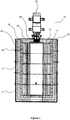
- thermal energy storage apparatus shown generally as (10).
- This thermal energy storage apparatus (10) includes a main housing block, shown generally as (12), which may or may not be sectionally constructed as shown by the general numbering (13) on Figure 1 .
- the thermal energy absorbing material of sintered graphite shown generally as (18) and (20), which is in communication with a wicking thermal energy absorbing material (22), which is in contact with location (24) of the Stirling engine (26).
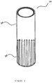
- the elongated canister (14) to which the elemental form of silicon material is enclosed therein includes along its outer circumferential side (34) a series of grooves or slots (36) which offers a greater surface for exchange between the thermal energy transfer of the elemental form of silicon material and the thermal energy absorbing material (18, 20) of the sintered graphite.
- the slots (36) on the external side (34) of the elongated canister (14) containing the elemental form of silicon material acts as heat sink in its ability to offer a greater surface area contact.
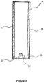
- Figure 3 shows a cross-sectional view of the elongated canister (14) containing the elemental form of silicon material, where can be seen at the base of the cylindrical structure (30), the lined refractory material, preferably ceramic, includes a pressure dispersion punt.
- Figure 4 shows that inside the main housing block (12) the elongated canisters containing the elemental form of silicon material can be of varying dimensions, wherein the first inner row of circumferentially arranged canisters (38) have a smaller dimension to the outer circumferential or second row (40), and where packed in between the respective elongated canisters (38) and (40) are a series of elongated rods (42) made up of sintered graphite material which act as the thermal energy absorbing material communicating between the elemental form of silicon material and the wicking material in communication with the Stirling engine (26).
- Figures 5 and 6 refer to a further preferred embodiment of this invention which has been introduced above with respect to the solar reflector arrangement in order to establish a focussing system to concentrate and collect as much the solar energy as possible directed towards the thermal energy storage apparatus.
- the main parabolic reflector (50) with its front concaved curved orientation providing the main dish surface (52) towards the source of solar, communicates or directs its captured energy, shown by way of lines (54), to a located lens and/or hyperbolic dish (56) which, by its own concaved arrangement, then in fact captures and reflects the energy back on to lens (58), which is then able to create a more concentrated focal point (60) to deliver the solar energy to the thermal energy storage apparatus (10).
- the reflector would be supported through a structure, shown generally as (62), and also on rollers and part of a control system, which would see its ability to also track the solar source in azimuthally and in various elevated directions.
- Figure 6 shows very simply and schematically how the main reflector (50) could be broken up into a series of segments to create the overall dish, wherein there could be spacing's (89) between the respective segments (99) to allow wind to pass through the reflector, rather than having high pressure winds try and deflect against the main reflector (50).
Landscapes
- Engineering & Computer Science (AREA)
- Mechanical Engineering (AREA)
- General Engineering & Computer Science (AREA)
- Physics & Mathematics (AREA)
- Thermal Sciences (AREA)
- Combustion & Propulsion (AREA)
- Chemical & Material Sciences (AREA)
- Sustainable Development (AREA)
- Sustainable Energy (AREA)
- Life Sciences & Earth Sciences (AREA)
- Silicon Compounds (AREA)
- Photovoltaic Devices (AREA)
- Central Heating Systems (AREA)
Claims (6)
- Wärmeenergiespeichervorrichtung (10), die dazu angepasst ist, Wärmequelleneintrag für die Entwicklung und im Wesentlichen kontinuierliche Zufuhr von Wärmeenergie zu einem Stirlingmotor (26) für die Übertragung dieser Wärmeenergie in elektrische und/oder mechanische Energie aufzunehmen, selbst während Perioden, in denen der Wärmequelleneintrag intermittierend oder für einen bestimmten Zeitraum nicht verfügbar ist, wobei die Vorrichtung (10) Folgendes einschließt:einen Hauptgehäuseblock (12), der innen eine Reihe von länglichen Behältern (14, 16, 38, 40) trägt, die aus feuerfestem Material, das mit einem wärmeenergie-absorbierenden Material (18, 20, 42) verschachtelt ist, hergestellt sind;wobei die länglichen feuerfesten Behälter (14, 16, 38, 40) eine elementare Form von Siliziummaterial enthalten, das dazu angepasst ist, Wärmeenergie aus dem verschachtelten und umgebenden wärmeenergieabsorbierenden Material (18, 20, 42) zu absorbieren, das in dem Hauptgehäuseblock (12) enthalten ist;wobei das Absorbieren von Wärmeenergie aus dem umgebenden wärmeenergieabsorbierenden Material (18, 20, 42) durch die elementare Form des Siliziummaterials eine physikalische Umwandlung von einem festen in einen flüssigen Zustand bewirkt, der es der elementaren Form des Siliziummaterials ermöglicht, die Wärmeenergie darin latent oder effektiv zu speichern, so dass, wenn das umgebende oder verschachtelte wärmeenergieabsorbierende Material (18, 20, 42) einen niedrigeren Temperaturgradienten aufweist als die Temperatur, die der elementaren Form des Siliziummaterials zugeordnet ist, eine Übertragung von Wärmeenergie aus dem länglichen Behälter (14, 16, 38, 40) zurück in das wärmeenergieabsorbierende Material (18, 20, 42) stattfindet;wobei das wärmeenergieabsorbierende Material (18, 20, 42) in Verbindung mit einem Material mit Dochtwirkung (22) steht, mit dem der Stirlingmotor (26) auch in Verbindung stehen kann, so dass die Wärmeenergieübertragung vom wärmeenergieabsorbierenden Material (18, 20, 42) in das Material mit Dochtwirkung (22) als Wärmeenergieeintrag in den Stirlingmotor (26) registriert wird, um die Übertragung der Wärmeenergie auf nutzbare mechanische und/oder elektrische Energie durch den Stirlingmotor (26) zu beginnen;wobei der längliche Behälter (14, 16, 38, 40), der einen zylindrischen Körper zur Aufnahme der elementaren Form von Siliziummaterial kombiniert, dadurch gekennzeichnet ist, dass der längliche Behälter (14, 16, 38, 40) eine innen ausgekleidete Kapselung aus feuerfestem Material aufweist und dadurch, dass das wärmeenergieabsorbierende Material (18, 20, 42) aus gesintertem Graphit besteht.
- Wärmeenergiespeichervorrichtung (10) nach Anspruch 1, wobei das gesinterte Graphitmaterial zu länglichen Stäben (42) verdichtet oder geformt ist, die gegen die jeweiligen länglichen Behälter (14, 16, 38, 40), die die elementare Form eines Siliziummaterials enthielten, verflochten und gepackt sind.
- Wärmeenergiespeichervorrichtung (10) nach Anspruch 1, wobei der längliche Behälter (14, 16, 38, 40) so konstruiert ist, dass er eine Reihe von Schlitzen oder Nuten (36) entlang eines Abschnitts seines Außenumfangs (34) beinhaltet.
- Wärmeenergiespeichervorrichtung (10) nach einem der Ansprüche 1 bis 3, wobei der Hauptgehäuseblock (12) der Wärmeenergiespeichervorrichtung (10) im Wesentlichen zylindrisch ist und darin eine Reihe von in einem Umfang umlaufenden einzelnen länglichen Behältern (14, 16, 38, 40) getragen wird.
- Wärmeenergiespeichervorrichtung (10) nach Anspruch 4, wobei zwei Reihen (38, 40), eine innere am Umfang positionierte, umlaufende Reihe (38) und eine äußere positionierte Reihe (40) von länglichen Behältern (14, 16, 38, 40) vorhanden sind, die innerhalb des wärmeenergieabsorbierenden Materials (18, 20, 42) innerhalb des Hauptgehäuseblocks (12) umlaufend getragen werden und miteinander verflochten sind.
- Wärmeenergiespeichervorrichtung (10) nach Anspruch 5, wobei die am inneren Umfang umlaufend positionierte Reihe (38) von länglichen Behältern (14, 16, 38, 40) einen kleineren Durchmesser aufweist als die außen umlaufend positionierte Reihe von länglichen Behältern (14, 16, 38, 40).
Applications Claiming Priority (2)
| Application Number | Priority Date | Filing Date | Title |
|---|---|---|---|
| AU2009903818A AU2009903818A0 (en) | 2009-08-14 | Thermal energy storage apparatus, arrangement and method | |
| PCT/AU2010/001035 WO2011017767A1 (en) | 2009-08-14 | 2010-08-13 | Thermal energy storage apparatus, arrangement and method |
Publications (3)
| Publication Number | Publication Date |
|---|---|
| EP2464865A1 EP2464865A1 (de) | 2012-06-20 |
| EP2464865A4 EP2464865A4 (de) | 2016-11-30 |
| EP2464865B1 true EP2464865B1 (de) | 2019-06-19 |
Family
ID=43585786
Family Applications (1)
| Application Number | Title | Priority Date | Filing Date |
|---|---|---|---|
| EP10807805.6A Active EP2464865B1 (de) | 2009-08-14 | 2010-08-13 | Vorrichtung, anordnung und verfahren zur speicherung von wärmeenergie |
Country Status (6)
| Country | Link |
|---|---|
| US (1) | US9052122B2 (de) |
| EP (1) | EP2464865B1 (de) |
| CN (1) | CN102656364B (de) |
| AU (1) | AU2010282232B2 (de) |
| NZ (1) | NZ598126A (de) |
| WO (1) | WO2011017767A1 (de) |
Families Citing this family (12)
| Publication number | Priority date | Publication date | Assignee | Title |
|---|---|---|---|---|
| WO2012078195A1 (en) | 2010-12-10 | 2012-06-14 | Vaporgenics,Inc. | Universal heat engine |
| CN103998889B (zh) * | 2011-08-09 | 2018-05-22 | 气候变化技术有限责任公司 | 热能存储装置 |
| DE102011052864A1 (de) * | 2011-08-19 | 2013-02-21 | Rehau Ag + Co. | Latentwärmespeichervorrichtung |
| WO2018104896A1 (en) * | 2016-12-08 | 2018-06-14 | Glynn Dr Patrick Joseph | Apparatus and methods for energy storage and retrieval |
| HRP20250185T1 (hr) * | 2017-05-03 | 2025-08-01 | Green Energy Investments IP Portfolio 3 FZC LLC | Aparat za skladištenje toplinske energije |
| HU231149B1 (hu) * | 2017-05-22 | 2021-03-29 | Péter Talabér | Szilárd töltetű hőtároló berendezés |
| WO2019178447A1 (en) | 2018-03-16 | 2019-09-19 | Lawrence Livermore National Security, Llc | Multi-fluid, earth battery energy systems and methods |
| US11137177B1 (en) | 2019-03-16 | 2021-10-05 | Vaporgemics, Inc | Internal return pump |
| AU2020243828B2 (en) | 2019-03-18 | 2026-04-02 | Esyantra Pty Ltd | An energy conversion, storage and retrieval device and method |
| US12578152B2 (en) | 2021-09-22 | 2026-03-17 | Wellhead Power Solutions, Llc | Thermal energy storage system |
| CN114739224B (zh) * | 2022-04-26 | 2024-01-05 | 徐州新风空调设备有限公司 | 一种环保型回风机的热能回收装置 |
| CN115406286A (zh) * | 2022-07-25 | 2022-11-29 | 施远 | 一种金属相变蓄热装置及金属相变蓄热模组 |
Family Cites Families (18)
| Publication number | Priority date | Publication date | Assignee | Title |
|---|---|---|---|---|
| US3224187A (en) * | 1964-05-04 | 1965-12-21 | Roger R Breihan | Hot gas engine |
| US4010614A (en) | 1974-11-13 | 1977-03-08 | Arthur David M | Solar radiation collector and system for converting and storing collected solar energy |
| SU920349A1 (ru) * | 1979-01-10 | 1982-04-15 | Предприятие П/Я А-1857 | Теплоаккумулирующий элемент теплообменника |
| US4335578A (en) * | 1980-05-30 | 1982-06-22 | Ford Aerospace & Communications Corporation | Solar power converter with pool boiling receiver and integral heat exchanger |
| US4642988A (en) * | 1981-08-14 | 1987-02-17 | New Process Industries, Inc. | Solar powered free-piston Stirling engine |
| SU1083068A1 (ru) * | 1983-01-07 | 1984-03-30 | Предприятие П/Я А-1857 | Способ изготовлени теплоаккумулирующего элемента теплообменника |
| US4586334A (en) | 1985-01-23 | 1986-05-06 | Nilsson Sr Jack E | Solar energy power generation system |
| US4768345A (en) * | 1986-10-03 | 1988-09-06 | Institute Of Gas Technology | Continuous thermal energy delivery from a periodically active energy source |
| US4807696A (en) * | 1987-12-10 | 1989-02-28 | Triangle Research And Development Corp. | Thermal energy storage apparatus using encapsulated phase change material |
| JP2746943B2 (ja) * | 1988-10-03 | 1998-05-06 | 工業技術院長 | 蓄熱器 |
| US5000252A (en) * | 1990-02-22 | 1991-03-19 | Wright State University | Thermal energy storage system |
| US5074283A (en) * | 1990-08-10 | 1991-12-24 | The United States Department Of Energy | Thermal storage module for solar dynamic receivers |
| US5083605A (en) * | 1990-08-17 | 1992-01-28 | Sundstrand Corporaiton | Self-pumping phase change thermal energy device |
| US5634339A (en) * | 1995-06-30 | 1997-06-03 | Ralph H. Lewis | Non-polluting, open brayton cycle automotive power unit |
| US8584734B2 (en) * | 2008-02-11 | 2013-11-19 | Navatek, Ltd | Two material phase change energy storage system |
| US8776784B2 (en) | 2008-06-27 | 2014-07-15 | The Boeing Company | Solar power device |
| CN101334012B (zh) * | 2008-07-18 | 2011-07-27 | 西安交通大学 | 一种分布式太阳能利用系统 |
| US7969075B2 (en) * | 2009-02-10 | 2011-06-28 | Lumenetix, Inc. | Thermal storage system using encapsulated phase change materials in LED lamps |
-
2010
- 2010-08-13 WO PCT/AU2010/001035 patent/WO2011017767A1/en not_active Ceased
- 2010-08-13 CN CN201080046291.8A patent/CN102656364B/zh active Active
- 2010-08-13 AU AU2010282232A patent/AU2010282232B2/en active Active
- 2010-08-13 US US13/390,357 patent/US9052122B2/en active Active
- 2010-08-13 NZ NZ598126A patent/NZ598126A/xx unknown
- 2010-08-13 EP EP10807805.6A patent/EP2464865B1/de active Active
Non-Patent Citations (1)
| Title |
|---|
| None * |
Also Published As
| Publication number | Publication date |
|---|---|
| US20120222415A1 (en) | 2012-09-06 |
| NZ598126A (en) | 2013-07-26 |
| CN102656364B (zh) | 2015-07-08 |
| AU2010282232A1 (en) | 2012-03-01 |
| CN102656364A (zh) | 2012-09-05 |
| EP2464865A1 (de) | 2012-06-20 |
| US9052122B2 (en) | 2015-06-09 |
| WO2011017767A1 (en) | 2011-02-17 |
| AU2010282232B2 (en) | 2016-02-04 |
| EP2464865A4 (de) | 2016-11-30 |
Similar Documents
| Publication | Publication Date | Title |
|---|---|---|
| AU2010282232B2 (en) | Thermal energy storage apparatus, arrangement and method | |
| US7051529B2 (en) | Solar dish concentrator with a molten salt receiver incorporating thermal energy storage | |
| US9705449B2 (en) | Effective and scalable solar energy collection and storage | |
| CA1265714A (en) | System for solar energy collection and recovery | |
| US4251291A (en) | Thermoelectric generator with latent heat storage | |
| CN108630334B (zh) | 全环境的自然循环微型一体化反应堆 | |
| CN104583686A (zh) | 聚光太阳能发电系统 | |
| US11085424B2 (en) | Solar power collection system and methods thereof | |
| CN104870924B (zh) | 热存储设备 | |
| US4172740A (en) | Solar energy system | |
| CN108954870B (zh) | 一种太阳能高温储能与换热吸热器 | |
| WO2016106745A1 (zh) | 一种模块化塔式太阳能光热发电系统 | |
| US20120011851A1 (en) | Solar Heat Collector | |
| ITRM20100428A1 (it) | Assorbitore di calore da radiazione solare per motore stirling | |
| CN211880329U (zh) | 一种可余热利用太阳能聚光发电装置 | |
| CN211552068U (zh) | 一种光聚热发电装置 | |
| WO2005050103B1 (en) | A large lens solar energy concentrator | |
| JP2009079510A (ja) | 太陽熱発電装置 | |
| KR20200047927A (ko) | 태양열을 이용한 발전장치 | |
| CA3238226A1 (en) | Jml hotstepper concentrated solar thermal power generation process | |
| CN202348474U (zh) | 碟式斯特林发动机高温热管吸热储热装置 | |
| KR100986459B1 (ko) | 태양열을 이용한 온수 생성장치 | |
| CN110864465A (zh) | 一种光聚热发电装置 | |
| KR20210065641A (ko) | 다기능 열교환기 | |
| CN109883064A (zh) | 一种太阳能集热器 |
Legal Events
| Date | Code | Title | Description |
|---|---|---|---|
| PUAI | Public reference made under article 153(3) epc to a published international application that has entered the european phase |
Free format text: ORIGINAL CODE: 0009012 |
|
| 17P | Request for examination filed |
Effective date: 20120207 |
|
| AK | Designated contracting states |
Kind code of ref document: A1 Designated state(s): AL AT BE BG CH CY CZ DE DK EE ES FI FR GB GR HR HU IE IS IT LI LT LU LV MC MK MT NL NO PL PT RO SE SI SK SM TR |
|
| DAX | Request for extension of the european patent (deleted) | ||
| RA4 | Supplementary search report drawn up and despatched (corrected) |
Effective date: 20161027 |
|
| RIC1 | Information provided on ipc code assigned before grant |
Ipc: F24J 2/48 20060101ALI20161021BHEP Ipc: F28D 20/00 20060101ALN20161021BHEP Ipc: F24J 2/34 20060101ALI20161021BHEP Ipc: F28D 20/02 20060101ALI20161021BHEP Ipc: F24J 2/42 20060101ALI20161021BHEP Ipc: F03G 6/06 20060101AFI20161021BHEP |
|
| RIC1 | Information provided on ipc code assigned before grant |
Ipc: F24S 60/00 20180101ALI20181219BHEP Ipc: F24S 20/20 20180101ALI20181219BHEP Ipc: F28D 20/02 20060101ALI20181219BHEP Ipc: F24S 30/45 20180101ALI20181219BHEP Ipc: F24S 23/71 20180101ALI20181219BHEP Ipc: F24S 23/30 20180101ALI20181219BHEP Ipc: F03G 6/06 20060101AFI20181219BHEP Ipc: F28D 20/00 20060101ALN20181219BHEP Ipc: F24S 23/79 20180101ALI20181219BHEP |
|
| GRAP | Despatch of communication of intention to grant a patent |
Free format text: ORIGINAL CODE: EPIDOSNIGR1 |
|
| STAA | Information on the status of an ep patent application or granted ep patent |
Free format text: STATUS: GRANT OF PATENT IS INTENDED |
|
| INTG | Intention to grant announced |
Effective date: 20190129 |
|
| GRAS | Grant fee paid |
Free format text: ORIGINAL CODE: EPIDOSNIGR3 |
|
| GRAA | (expected) grant |
Free format text: ORIGINAL CODE: 0009210 |
|
| STAA | Information on the status of an ep patent application or granted ep patent |
Free format text: STATUS: THE PATENT HAS BEEN GRANTED |
|
| AK | Designated contracting states |
Kind code of ref document: B1 Designated state(s): AL AT BE BG CH CY CZ DE DK EE ES FI FR GB GR HR HU IE IS IT LI LT LU LV MC MK MT NL NO PL PT RO SE SI SK SM TR |
|
| REG | Reference to a national code |
Ref country code: GB Ref legal event code: FG4D |
|
| REG | Reference to a national code |
Ref country code: CH Ref legal event code: EP |
|
| REG | Reference to a national code |
Ref country code: IE Ref legal event code: FG4D |
|
| REG | Reference to a national code |
Ref country code: DE Ref legal event code: R096 Ref document number: 602010059573 Country of ref document: DE |
|
| REG | Reference to a national code |
Ref country code: AT Ref legal event code: REF Ref document number: 1145851 Country of ref document: AT Kind code of ref document: T Effective date: 20190715 |
|
| REG | Reference to a national code |
Ref country code: NL Ref legal event code: MP Effective date: 20190619 |
|
| PG25 | Lapsed in a contracting state [announced via postgrant information from national office to epo] |
Ref country code: LT Free format text: LAPSE BECAUSE OF FAILURE TO SUBMIT A TRANSLATION OF THE DESCRIPTION OR TO PAY THE FEE WITHIN THE PRESCRIBED TIME-LIMIT Effective date: 20190619 Ref country code: HR Free format text: LAPSE BECAUSE OF FAILURE TO SUBMIT A TRANSLATION OF THE DESCRIPTION OR TO PAY THE FEE WITHIN THE PRESCRIBED TIME-LIMIT Effective date: 20190619 Ref country code: FI Free format text: LAPSE BECAUSE OF FAILURE TO SUBMIT A TRANSLATION OF THE DESCRIPTION OR TO PAY THE FEE WITHIN THE PRESCRIBED TIME-LIMIT Effective date: 20190619 Ref country code: AL Free format text: LAPSE BECAUSE OF FAILURE TO SUBMIT A TRANSLATION OF THE DESCRIPTION OR TO PAY THE FEE WITHIN THE PRESCRIBED TIME-LIMIT Effective date: 20190619 Ref country code: SE Free format text: LAPSE BECAUSE OF FAILURE TO SUBMIT A TRANSLATION OF THE DESCRIPTION OR TO PAY THE FEE WITHIN THE PRESCRIBED TIME-LIMIT Effective date: 20190619 Ref country code: NO Free format text: LAPSE BECAUSE OF FAILURE TO SUBMIT A TRANSLATION OF THE DESCRIPTION OR TO PAY THE FEE WITHIN THE PRESCRIBED TIME-LIMIT Effective date: 20190919 |
|
| REG | Reference to a national code |
Ref country code: LT Ref legal event code: MG4D |
|
| PG25 | Lapsed in a contracting state [announced via postgrant information from national office to epo] |
Ref country code: GR Free format text: LAPSE BECAUSE OF FAILURE TO SUBMIT A TRANSLATION OF THE DESCRIPTION OR TO PAY THE FEE WITHIN THE PRESCRIBED TIME-LIMIT Effective date: 20190920 Ref country code: BG Free format text: LAPSE BECAUSE OF FAILURE TO SUBMIT A TRANSLATION OF THE DESCRIPTION OR TO PAY THE FEE WITHIN THE PRESCRIBED TIME-LIMIT Effective date: 20190919 Ref country code: LV Free format text: LAPSE BECAUSE OF FAILURE TO SUBMIT A TRANSLATION OF THE DESCRIPTION OR TO PAY THE FEE WITHIN THE PRESCRIBED TIME-LIMIT Effective date: 20190619 |
|
| REG | Reference to a national code |
Ref country code: AT Ref legal event code: MK05 Ref document number: 1145851 Country of ref document: AT Kind code of ref document: T Effective date: 20190619 |
|
| PG25 | Lapsed in a contracting state [announced via postgrant information from national office to epo] |
Ref country code: PT Free format text: LAPSE BECAUSE OF FAILURE TO SUBMIT A TRANSLATION OF THE DESCRIPTION OR TO PAY THE FEE WITHIN THE PRESCRIBED TIME-LIMIT Effective date: 20191021 Ref country code: AT Free format text: LAPSE BECAUSE OF FAILURE TO SUBMIT A TRANSLATION OF THE DESCRIPTION OR TO PAY THE FEE WITHIN THE PRESCRIBED TIME-LIMIT Effective date: 20190619 Ref country code: EE Free format text: LAPSE BECAUSE OF FAILURE TO SUBMIT A TRANSLATION OF THE DESCRIPTION OR TO PAY THE FEE WITHIN THE PRESCRIBED TIME-LIMIT Effective date: 20190619 Ref country code: SK Free format text: LAPSE BECAUSE OF FAILURE TO SUBMIT A TRANSLATION OF THE DESCRIPTION OR TO PAY THE FEE WITHIN THE PRESCRIBED TIME-LIMIT Effective date: 20190619 Ref country code: RO Free format text: LAPSE BECAUSE OF FAILURE TO SUBMIT A TRANSLATION OF THE DESCRIPTION OR TO PAY THE FEE WITHIN THE PRESCRIBED TIME-LIMIT Effective date: 20190619 Ref country code: NL Free format text: LAPSE BECAUSE OF FAILURE TO SUBMIT A TRANSLATION OF THE DESCRIPTION OR TO PAY THE FEE WITHIN THE PRESCRIBED TIME-LIMIT Effective date: 20190619 Ref country code: CZ Free format text: LAPSE BECAUSE OF FAILURE TO SUBMIT A TRANSLATION OF THE DESCRIPTION OR TO PAY THE FEE WITHIN THE PRESCRIBED TIME-LIMIT Effective date: 20190619 |
|
| PG25 | Lapsed in a contracting state [announced via postgrant information from national office to epo] |
Ref country code: IS Free format text: LAPSE BECAUSE OF FAILURE TO SUBMIT A TRANSLATION OF THE DESCRIPTION OR TO PAY THE FEE WITHIN THE PRESCRIBED TIME-LIMIT Effective date: 20191019 Ref country code: SM Free format text: LAPSE BECAUSE OF FAILURE TO SUBMIT A TRANSLATION OF THE DESCRIPTION OR TO PAY THE FEE WITHIN THE PRESCRIBED TIME-LIMIT Effective date: 20190619 Ref country code: ES Free format text: LAPSE BECAUSE OF FAILURE TO SUBMIT A TRANSLATION OF THE DESCRIPTION OR TO PAY THE FEE WITHIN THE PRESCRIBED TIME-LIMIT Effective date: 20190619 Ref country code: IT Free format text: LAPSE BECAUSE OF FAILURE TO SUBMIT A TRANSLATION OF THE DESCRIPTION OR TO PAY THE FEE WITHIN THE PRESCRIBED TIME-LIMIT Effective date: 20190619 |
|
| PG25 | Lapsed in a contracting state [announced via postgrant information from national office to epo] |
Ref country code: TR Free format text: LAPSE BECAUSE OF FAILURE TO SUBMIT A TRANSLATION OF THE DESCRIPTION OR TO PAY THE FEE WITHIN THE PRESCRIBED TIME-LIMIT Effective date: 20190619 |
|
| PG25 | Lapsed in a contracting state [announced via postgrant information from national office to epo] |
Ref country code: DK Free format text: LAPSE BECAUSE OF FAILURE TO SUBMIT A TRANSLATION OF THE DESCRIPTION OR TO PAY THE FEE WITHIN THE PRESCRIBED TIME-LIMIT Effective date: 20190619 Ref country code: PL Free format text: LAPSE BECAUSE OF FAILURE TO SUBMIT A TRANSLATION OF THE DESCRIPTION OR TO PAY THE FEE WITHIN THE PRESCRIBED TIME-LIMIT Effective date: 20190619 |
|
| PG25 | Lapsed in a contracting state [announced via postgrant information from national office to epo] |
Ref country code: IS Free format text: LAPSE BECAUSE OF FAILURE TO SUBMIT A TRANSLATION OF THE DESCRIPTION OR TO PAY THE FEE WITHIN THE PRESCRIBED TIME-LIMIT Effective date: 20200224 Ref country code: CH Free format text: LAPSE BECAUSE OF NON-PAYMENT OF DUE FEES Effective date: 20190831 Ref country code: LI Free format text: LAPSE BECAUSE OF NON-PAYMENT OF DUE FEES Effective date: 20190831 Ref country code: LU Free format text: LAPSE BECAUSE OF NON-PAYMENT OF DUE FEES Effective date: 20190813 Ref country code: MC Free format text: LAPSE BECAUSE OF FAILURE TO SUBMIT A TRANSLATION OF THE DESCRIPTION OR TO PAY THE FEE WITHIN THE PRESCRIBED TIME-LIMIT Effective date: 20190619 |
|
| REG | Reference to a national code |
Ref country code: BE Ref legal event code: MM Effective date: 20190831 |
|
| REG | Reference to a national code |
Ref country code: DE Ref legal event code: R097 Ref document number: 602010059573 Country of ref document: DE |
|
| PLBE | No opposition filed within time limit |
Free format text: ORIGINAL CODE: 0009261 |
|
| STAA | Information on the status of an ep patent application or granted ep patent |
Free format text: STATUS: NO OPPOSITION FILED WITHIN TIME LIMIT |
|
| PG2D | Information on lapse in contracting state deleted |
Ref country code: IS |
|
| PG25 | Lapsed in a contracting state [announced via postgrant information from national office to epo] |
Ref country code: FR Free format text: LAPSE BECAUSE OF NON-PAYMENT OF DUE FEES Effective date: 20190819 Ref country code: IE Free format text: LAPSE BECAUSE OF NON-PAYMENT OF DUE FEES Effective date: 20190813 |
|
| 26N | No opposition filed |
Effective date: 20200603 |
|
| PG25 | Lapsed in a contracting state [announced via postgrant information from national office to epo] |
Ref country code: BE Free format text: LAPSE BECAUSE OF NON-PAYMENT OF DUE FEES Effective date: 20190831 Ref country code: SI Free format text: LAPSE BECAUSE OF FAILURE TO SUBMIT A TRANSLATION OF THE DESCRIPTION OR TO PAY THE FEE WITHIN THE PRESCRIBED TIME-LIMIT Effective date: 20190619 |
|
| PG25 | Lapsed in a contracting state [announced via postgrant information from national office to epo] |
Ref country code: CY Free format text: LAPSE BECAUSE OF FAILURE TO SUBMIT A TRANSLATION OF THE DESCRIPTION OR TO PAY THE FEE WITHIN THE PRESCRIBED TIME-LIMIT Effective date: 20190619 |
|
| PG25 | Lapsed in a contracting state [announced via postgrant information from national office to epo] |
Ref country code: MT Free format text: LAPSE BECAUSE OF FAILURE TO SUBMIT A TRANSLATION OF THE DESCRIPTION OR TO PAY THE FEE WITHIN THE PRESCRIBED TIME-LIMIT Effective date: 20190619 Ref country code: HU Free format text: LAPSE BECAUSE OF FAILURE TO SUBMIT A TRANSLATION OF THE DESCRIPTION OR TO PAY THE FEE WITHIN THE PRESCRIBED TIME-LIMIT; INVALID AB INITIO Effective date: 20100813 |
|
| PG25 | Lapsed in a contracting state [announced via postgrant information from national office to epo] |
Ref country code: MK Free format text: LAPSE BECAUSE OF FAILURE TO SUBMIT A TRANSLATION OF THE DESCRIPTION OR TO PAY THE FEE WITHIN THE PRESCRIBED TIME-LIMIT Effective date: 20190619 |
|
| PGFP | Annual fee paid to national office [announced via postgrant information from national office to epo] |
Ref country code: GB Payment date: 20250618 Year of fee payment: 16 |
|
| PGFP | Annual fee paid to national office [announced via postgrant information from national office to epo] |
Ref country code: DE Payment date: 20250827 Year of fee payment: 16 |