EP2464526B1 - Buchbindevorrichtung - Google Patents
Buchbindevorrichtung Download PDFInfo
- Publication number
- EP2464526B1 EP2464526B1 EP10807800.7A EP10807800A EP2464526B1 EP 2464526 B1 EP2464526 B1 EP 2464526B1 EP 10807800 A EP10807800 A EP 10807800A EP 2464526 B1 EP2464526 B1 EP 2464526B1
- Authority
- EP
- European Patent Office
- Prior art keywords
- binding apparatus
- edge
- guiding means
- panel
- book block
- Prior art date
- Legal status (The legal status is an assumption and is not a legal conclusion. Google has not performed a legal analysis and makes no representation as to the accuracy of the status listed.)
- Not-in-force
Links
- 230000002093 peripheral effect Effects 0.000 claims description 14
- 239000000853 adhesive Substances 0.000 claims description 7
- 230000001070 adhesive effect Effects 0.000 claims description 7
- 230000000284 resting effect Effects 0.000 claims description 6
- 238000000034 method Methods 0.000 description 3
- 238000012986 modification Methods 0.000 description 2
- 230000004048 modification Effects 0.000 description 2
- 229910000831 Steel Inorganic materials 0.000 description 1
- 230000000694 effects Effects 0.000 description 1
- 238000004519 manufacturing process Methods 0.000 description 1
- 230000002028 premature Effects 0.000 description 1
- 239000010959 steel Substances 0.000 description 1
Images



Classifications
-
- B—PERFORMING OPERATIONS; TRANSPORTING
- B42—BOOKBINDING; ALBUMS; FILES; SPECIAL PRINTED MATTER
- B42C—BOOKBINDING
- B42C11/00—Casing-in
- B42C11/04—Machines or equipment for casing-in or applying covers to books
-
- B—PERFORMING OPERATIONS; TRANSPORTING
- B42—BOOKBINDING; ALBUMS; FILES; SPECIAL PRINTED MATTER
- B42C—BOOKBINDING
- B42C9/00—Applying glue or adhesive peculiar to bookbinding
- B42C9/0056—Applying glue or adhesive peculiar to bookbinding applying tape or covers precoated with adhesive to a stack of sheets
-
- B—PERFORMING OPERATIONS; TRANSPORTING
- B42—BOOKBINDING; ALBUMS; FILES; SPECIAL PRINTED MATTER
- B42D—BOOKS; BOOK COVERS; LOOSE LEAVES; PRINTED MATTER CHARACTERISED BY IDENTIFICATION OR SECURITY FEATURES; PRINTED MATTER OF SPECIAL FORMAT OR STYLE NOT OTHERWISE PROVIDED FOR; DEVICES FOR USE THEREWITH AND NOT OTHERWISE PROVIDED FOR; MOVABLE-STRIP WRITING OR READING APPARATUS
- B42D3/00—Book covers
- B42D3/002—Covers or strips provided with adhesive for binding
Definitions
- This invention relates to a binding apparatus suitable for binding printed matter.
- the invention relates particularly but not restricted to placement of a book block in relation to a book cover in a book binding process.
- a binding apparatus for facilitating placement of a book block in relation to a cover having front and back panels for subsequent attachment of the book block to the cover, the apparatus including:
- the book block may include a pile of loose leaves bound between front and back fly sheets.
- the loose leaves may include heavy paper such as gloss paper.
- the first and second guiding means in combination secure the book cover in a predetermined position. More preferably, the first and second guiding means are substantially perpendicular to each other.
- the apparatus includes a grid having first, second and third bars.
- the bars are preferred to be spaced apart and parallel to one another.
- the bars may be configured and arranged such that the first bar provides support for the first edge of the front panel, the second bar for at least part of a spine panel, and the third bar for a first edge of the back panel, respectively.
- the grid is also preferred to include first and second rails which movably interlock with and run substantially perpendicular to the bars.
- the rails are preferred to be spaced apart to support the second edge of the front panel and an opposing edge, respectively.
- the rails also support a second edge and another opposing edge of the back panel, respectively.
- the second rail may be designed so that it is slidable along the length of the bars to suit covers of different dimensions.
- the cover also preferably includes a spine panel adjoining the front and back panels.
- the cover is preferred to be rested on the grid in an unfolded state.
- the first guiding means is preferred to include a bracket which is mounted to the first bar.
- the bracket in this embodiment is L-shaped, having vertical and horizontal members.
- the vertical member preferably includes a slot adapted to movably receive the first positioning element.
- the second guiding means is preferred to include a wall adapted in use to abut the second edge of the front panel (and back panel).
- the wall is disposed in an upright position substantially perpendicular to the base.
- At least part of the first positioning element is preferred to be located above the cover resting on the grid. It is preferred that the first positioning element is adjustable to a desired position to provide in use a first margin between the first edge of the front panel and a first peripheral surface of the book block.
- the second positioning element is preferred to be located above the cover resting on the grid. It is preferred that the second positioning element is adjustable to a desired position to in use provide a second margin between the second edge of the front panel and a second peripheral surface of the book block.
- the apparatus of the present invention also includes a third guiding means adapted to abut the opposing edge of the front panel.
- the third guiding means includes a bracket adapted to be movably mounted on the first and second bars.
- the third guiding means may be locked to the bars by fixing means.
- the fixing means may include a biasing means adapted to facilitate gliding of the third guiding means on the bars.
- the fixing means may include one or more screws with a spring loaded device.
- the third guiding means includes a bevel adapted in use to direct the block of bound paper towards the second positioning element thereby achieving placement of the block in the desired position with respect to the cover.
- a front fly sheet of the book block may be attached to a predetermined part of the spine panel of the cover resting on the structure via an adhesive member.
- the back panel may then be folded over onto a back fly sheet of the book block so as to bond another predetermined part of the spine panel to the back fly sheet.
- the height of the vertical member of the first guiding means is preferred to be higher than the thickness of the book block.
- the height of the wall of the second guiding means is preferred to be higher than the thickness of the book block.
- the spine panel has another adhesive member adapted to bond the back panel to the back fly sheet when the back panel is folded onto and pressed against the back fly sheet.
- a binding apparatus 10 supports an unfolded book cover 16 having a front panel 28, a spine panel 30 and a back panel 32.
- the book cover 16 is to be bonded to a book block 44 which comprises a pile of loose leaves intermediate front and back fly sheets 66 and 68.
- the loose leaves and the fly sheets 66 and 68 are bound by steel stitches or staples.
- the loose leaves in the present embodiment include gloss paper for photos.
- the apparatus 10 has a grid with first, second and third bars 20, 22 and 24 which are spaced apart and parallel to one another.
- the first bar 20 provides support for a lateral edge 58 of the front panel 28.
- the second bar 22 is located intermediate the first and third bars 20 and 24 to provide support for the spine panel 30.
- the third bar 24 supports a lateral edge 92 of the back panel 32.
- the grid also includes first and second transverse rails 36 and 38 which movably interlock with and run substantially perpendicular to each of the bars 20, 22 and 24.
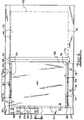
- the rails 36 and 38 are spaced apart to support top and bottom edges 35 and 37 (see Figure 4 ) of the front panel 28 as well as top and bottom edges 40 and 42 (see Figure 4 ) of the back panel 32.
- the rail 38 is slidable along the length of the bars 20, 22 and 24 to suit covers of different dimensions. As best shown in Figure 4 , the panels 28, 30 and 32 are supported by the grid and ready for placement of the book block 44 thereon.
- the binding apparatus 10 has a guiding means which is movably connected to the bar 20.
- the guiding means is in the form of a bracket 46 which is mounted to the bar 20 and in use guides the lateral edge 58 of the front panel 28 (refer Figure 1 ).
- the bracket 46 is L-shaped having vertical and horizontal members 48 and 50, respectively.
- the vertical member 48 includes a slot 52 which receives a movable positioning element in the form of a plate 54.
- the binding apparatus 10 also has another guiding means in the form of a wall 56 which in use guides and abuts the top edges 35 and 40 of the front and back panels 28 and 32.
- the wall 55 is disposed in an upright position substantially perpendicular to the grid.
- the plate 54 in use abuts part of a peripheral surface 60 of the book block 44.
- positioning element in the form of a plate 62 is movably attached to the wall 56 and abuts part of a second peripheral surface 64 of the book block 44.
- the plate 54 is located above the cover 16 resting on the base. Referring to Figures 3 and 4 , the plate 54 is adjustable to move forward and backward as indicated by the arrows A-A in Figures 3 and 4 to a desired position to provide in use a margin B-B between the lateral edge 58 (see Figure 4 ) of the front panel and the first peripheral surface 60 of the book block 44.
- the plate 62 is located above the cover 16 which rests on the base.
- the plate 62 is adjustable to move forward and backward as indicated by arrows C-C (see Figure 4 ) to a desired position to provide in use a margin D-D between the top edge 35 of the front panel and the second peripheral surface 64 of the book block 44.
- the plates 54 and 62 are substantially perpendicular to each other.
- the binding apparatus 10 also includes a further guiding means which takes the form of an L-shaped bracket 70.
- the bracket 70 in use abuts a bottom edge 72 of the front panel 28.
- the bracket 70 is movably mounted on the bars 20 and 22. Once moved to a desired location, the bracket 70 can be locked in place by fixing means such as screws 74 and 76.
- Each of the screws 74 and 76 includes an enlarged head portion to facilitate gripping by a user.
- the bracket 70 assists in securing the book block 44 in the desired position for bonding of the book block 44 to the book cover 16.
- the bracket 70 includes a bevel 78 with a slanted surface.
- the bevel 78 is convenient to placement of the book block 44 in that it directs the book block 44 of bound paper towards the plate 62.
- the first step is to place the book cover 16 on the base.
- the cover 16 is to be rested on the base in an unfolded state.
- the cover 16 is then pushed against the bracket 46 and wall 56 such that the edges 58 and 35 of the front panel 28 abut the bracket 46 and wall 56, respectively.
- bracket 70 is brought into contact with the edge 72 of the front panel 28. This further secures the cover 16 in position.
- the plates 54 and 62 are then adjusted to the desired positions, respectively.
- screws 82, 84, 86, 88 and 90 each of which has an enlarged head portion, are loosened to allow the respective plates 54 and 62 to slide forward or backward to a desired position.
- the positions of the respective plates 54 and 62 are dictated by the desired margins B-B and D-D.
- the plates 54 and 62 in combination secure the book block 44 in the desired position in relation to the front and back panels 28 and 32.
- the book block 44 may be put onto the front panel 28 of the cover 16.
- the block 44 should be positioned in such a way that the bottom edge 84 of the book block 44 is aligned with the bevel 78.
- the book block 44 is directed towards the wall 56 resulting in the peripheral surface 64 of the block 44 abutting the plate 62.
- the book block 44 is pushed laterally towards the bracket 46 such that the peripheral surface 60 abuts the plate 54.
- the above steps should be carried out with dexterity so as to avoid premature engagement of the front fly sheet 66 near a rear end 86 of the book block 44 with an adhesive member 88 provided on the spine panel 30.
- the adhesive member 88 is preserved by a tape 90a which is to be peeled off exposing the adhesive when the block 44 is in position for engagement with the cover 16.
- the back panel 32 is folded onto the back fly sheet 68 so as to effect bonding of another adhesive member 90b (refer Figure 1 ) provided on the spine panel 30 to the back fly sheet 68.
- another adhesive member 90b (refer Figure 1 ) provided on the spine panel 30 to the back fly sheet 68.
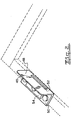
- the lateral edge 92 of the back panel 32 is brought into contact with the upper portion 94 of the bracket 46.
- the height of the vertical member 48 of the bracket 46 is higher than the thickness of the book block 44.
- the lateral edge 92 of the back panel 32 can be pushed laterally to abut the upper portion 94 (see Figures 1 and 5 ) of the bracket 46 thereby achieving accurate alignment of the back panel 32 with the front panel 28.
- the height of the wall 56 is higher than the thickness of the book block 44.
- the binding apparatus may offer at least the following advantages:
- the binding apparatus of the present invention is industrially applicable in that it facilitates swift attachment of a book block to a cover with a high degree of precision for the production a permanently bound book.
Landscapes
- Engineering & Computer Science (AREA)
- Mechanical Engineering (AREA)
- Folding Of Thin Sheet-Like Materials, Special Discharging Devices, And Others (AREA)
- Sheet Holders (AREA)
- Basic Packing Technique (AREA)
Claims (21)
- Bindevorrichtung (10) zum Erleichtern des Platzierens eines Buchblocks (44) in Bezug auf einen Umschlag (68) mit einem vorderen (28) und einem hinteren (32) Deckel zum darauffolgenden Befestigen des Buchblocks am Umschlag, wobei die Vorrichtung Folgendes umfasst:ein erstes Führungsmittel (46), angepasst, um eine erste Kante (58) des vorderen Deckels zu führen;ein zweites Führungsmittel (56), angepasst, um eine zweite Kante des vorderen Deckels zu führen;ein erstes Positionierungselement (54) beweglich befestigt am ersten Führungsmittel und angepasst, um im Gebrauch an wenigstens einem Teil einer ersten Umfangsoberfläche (60) des Buchblocks anzustoßen; undein zweites Positionierungselement (62), angebaut am zweiten Führungsmittel und angepasst, um im Gebrauch wenigstens an einem Teil einer zweiten Umfangsoberfläche (64) des Buchblocks anzustoßen, dadurch gekennzeichnet, dass beide Positionierungsmittel beweglich an dem jeweiligen Führungsmittel befestigt sind.
- Bindevorrichtung nach Anspruch 1, wobei das erste und das zweite Positionierungsmittel angepasst sind, zusammenzuwirken, um den Buchumschlag an einer vorherbestimmten Position zu fixieren.
- Bindevorrichtung nach Anspruch 1 oder 2, wobei die Vorrichtung einen Rahmen mit einem ersten, einem zweiten und einem dritten Stab aufweist, wobei die Stäbe derart konfiguriert und angeordnet sind, dass der erste Stab die erste Kante des vorderen Deckels, die zweite Stange wenigstens einen Teil des Buchrückens beziehungsweise die dritte Stange eine erste Kante des hinteren Deckels stützt.
- Bindevorrichtung nach Anspruch 3, wobei der Rahmen auch eine erste und eine zweite Schiene aufweist, die eine zweite Kante des hinteren Deckels beziehungsweise eine gegenüber angeordnete Kante stützen.
- Bindevorrichtung nach Anspruch 4, wobei die zweite Schiene derart gestaltet ist, dass sie entlang der Länge der Stäbe verschiebbar ist, um Buchumschläge mit unterschiedlichen Abmessungen aufzunehmen.
- Bindevorrichtung nach einem der vorhergehenden Ansprüche, wobei der Umschlag auch einen Buchrücken aufweist, der an den vorderen und den hinteren Deckel angrenzt.
- Bindevorrichtung nach einem der Ansprüche 3 bis 6, wobei das erste Führungsmittel einen Halter umfasst, der am ersten Stab angebracht ist.
- Bindevorrichtung nach Anspruch 7, wobei der Halter ein vertikales Element umfasst, welches einen Schlitz aufweist, der angepasst ist, das erste Positionierungselement beweglich aufzunehmen.
- Bindevorrichtung nach einem der vorhergehenden Ansprüche, wobei das zweite Führungsmittel eine Wand aufweist, die angepasst ist, im Gebrauch an die zweite Kante des vorderen Deckels anzustoßen.
- Bindevorrichtung nach Anspruch 9, wobei die Wand in einer aufrechten Position im Wesentlichen senkrecht zur Basis angeordnet ist.
- Bindevorrichtung nach einem der Ansprüche 3 bis 10, wobei wenigstens ein Teil des ersten Positionierungselements über der Abdeckung angeordnet ist, die auf dem Rahmen aufliegt.
- Bindevorrichtung nach einem der vorhergehenden Ansprüche, wobei das erste Positionierungselement auf eine gewünschte Position einstellbar ist, um im Gebrauch einen ersten Rand zwischen der ersten Kante des vorderen Deckels und einer ersten Umfangsoberfläche des Buchblocks bereitzustellen.
- Bindevorrichtung nach einem der Ansprüche 3 bis 12, wobei wenigstens ein Teil des zweiten Positionierungselements über der Abdeckung angeordnet ist, die auf dem Rahmen aufliegt.
- Bindevorrichtung nach einem der vorhergehenden Ansprüche, wobei das zweite Positionierungselement auf eine gewünschte Höhe einstellbar ist, um im Gebrauch einen zweiten Rand zwischen der zweiten Kante des vorderen Deckels und einer zweiten umlaufenden Oberfläche des Buchblocks bereitzustellen.
- Bindevorrichtung nach einem der vorhergehenden Ansprüche, die ein drittes Führungsmittel mit einem Halter umfasst, der angepasst ist, um beweglich auf dem ersten und dem zweiten Stab angebracht zu sein.
- Bindevorrichtung nach Anspruch 15, wobei das dritte Führungsmittel eine Schräge aufweist, die angepasst ist, im Gebrauch den Block gebundenes Papier in die Richtung des zweiten Positionierungselements zu führen, um so eine Platzierung des Blocks bezogen auf den Umschlag in der gewünschten Position zu erreichen.
- Bindevorrichtung nach einem der Ansprüche 8 bis 16, wobei die Höhe des vertikalen Elements des ersten Führungsmittels größer ist als die Dicke des Buchblocks.
- Bindevorrichtung nach einem der vorhergehenden Ansprüche, wobei, wenn im Gebrauch der hintere Deckel auf den Buchblock gefaltet wird, eine erste Kante des hinteren Deckels an das erste Führungsmittel anstößt, wodurch die erste Kante des hinteren Deckels an der ersten Kante des vorderen Deckels ausgerichtet wird.
- Bindevorrichtung nach einem der Ansprüche 9 bis 18, wobei die Höhe der Wand des zweiten Führungsmittels größer ist als die Dicke des Buchblocks.
- Bindevorrichtung nach einem der vorhergehenden Ansprüche, wobei, wenn im Gebrauch der hintere Deckel auf den Buchblock gefaltet wird, eine zweite Kante des hinteren Deckels an das zweite Führungsmittel anstößt, wodurch die zweite Kante des hinteren Deckels an der zweiten Kante des vorderen Deckels ausgerichtet wird.
- Bindevorrichtung nach einem der Ansprüche 3 bis 20, wobei der Buchrücken ein weiteres Klebeelement aufweist, angepasst, um den hintere Deckels mit einem hinteren fliegenden Blatt zu verbinden, wenn der hintere Deckel auf das hintere fliegende Blatt gefaltet und aufgepresst wird.
Applications Claiming Priority (2)
| Application Number | Priority Date | Filing Date | Title |
|---|---|---|---|
| AU2009903742A AU2009903742A0 (en) | 2009-08-11 | A binding apparatus | |
| PCT/AU2010/001030 WO2011017762A1 (en) | 2009-08-11 | 2010-08-11 | A book binding apparatus |
Publications (3)
| Publication Number | Publication Date |
|---|---|
| EP2464526A1 EP2464526A1 (de) | 2012-06-20 |
| EP2464526A4 EP2464526A4 (de) | 2013-12-04 |
| EP2464526B1 true EP2464526B1 (de) | 2017-04-12 |
Family
ID=43585781
Family Applications (1)
| Application Number | Title | Priority Date | Filing Date |
|---|---|---|---|
| EP10807800.7A Not-in-force EP2464526B1 (de) | 2009-08-11 | 2010-08-11 | Buchbindevorrichtung |
Country Status (9)
| Country | Link |
|---|---|
| US (1) | US8870511B2 (de) |
| EP (1) | EP2464526B1 (de) |
| JP (1) | JP5715626B2 (de) |
| CN (1) | CN102656020B (de) |
| AU (1) | AU2010282227B2 (de) |
| CA (1) | CA2770907A1 (de) |
| NZ (1) | NZ598735A (de) |
| SG (1) | SG178392A1 (de) |
| WO (1) | WO2011017762A1 (de) |
Families Citing this family (3)
| Publication number | Priority date | Publication date | Assignee | Title |
|---|---|---|---|---|
| CN102320197B (zh) * | 2011-09-15 | 2015-07-22 | 大进科技(杭州)有限公司 | 精装书上书定位夹具的使用方法 |
| BE1022002B1 (nl) * | 2014-05-13 | 2016-02-03 | Unibind Limited | Werkwijze voor het vervaardigen van een panoramaboek en van een boekblok van een panoramaboek en vouwapparaat voor het dubbelvouwen van bladen, positioneringselement en uitlijnapparaat daarbij toegepast |
| CN114834175A (zh) * | 2022-04-07 | 2022-08-02 | 安徽美阅文化发展股份有限公司 | 一种封皮笔记本用塞包辅助工具 |
Family Cites Families (18)
| Publication number | Priority date | Publication date | Assignee | Title |
|---|---|---|---|---|
| US1114740A (en) * | 1913-06-04 | 1914-10-27 | Theodore S Etheridge | Device for attaching book-covers. |
| US1274154A (en) * | 1917-03-31 | 1918-07-30 | Theodore S Etheridge | Pamphlet-covering machine. |
| GB192239A (en) * | 1921-11-30 | 1923-02-01 | Automatic Recording Safe Compa | Improvements in or relating to apparatus for assembling the members of book-form safes |
| US1460348A (en) * | 1922-03-23 | 1923-06-26 | Christian B Nelson | Book-cover gauge |
| US2021214A (en) * | 1933-04-08 | 1935-11-19 | Wilson Walter John William | Bookbinder's case gauge |
| US2150104A (en) * | 1936-05-25 | 1939-03-07 | Picture Cover Bindings Inc | Apparatus for making book covers |
| US2943336A (en) * | 1959-06-15 | 1960-07-05 | Gaylord Bros Inc | Apparatus for use in assembling and applying book covers |
| US3825964A (en) * | 1973-04-17 | 1974-07-30 | Velo Bind Inc | Device and method for casing books |
| US3952356A (en) * | 1975-02-21 | 1976-04-27 | Minnesota Mining & Manufacturing Company | Gauge and alignment device for attaching covers to books |
| US5044857A (en) * | 1988-08-29 | 1991-09-03 | Velobind, Inc. | Casing-in machine |
| JPH03112687A (ja) * | 1989-09-20 | 1991-05-14 | Rr Donnelley & Sons Co | 製本装置 |
| JPH07290857A (ja) * | 1994-04-18 | 1995-11-07 | Xerox Corp | ケース・バウンド・ブック組立装置 |
| FI103100B1 (fi) * | 1998-02-09 | 1999-04-30 | Instant Cover Europ Oy Ltd | Menetelmä ja laite kirjankansien sitomiseksi sekä menetelmän mukaisesti sidottu kirja |
| CN2430282Y (zh) * | 2000-06-29 | 2001-05-16 | 浙江先锋机械厂 | 包本机上用于粘贴封面的包本机构 |
| US7134822B2 (en) * | 2002-10-02 | 2006-11-14 | Powis Parker Inc. | Guide apparatus for use in making a hardcover book |
| US20040066029A1 (en) * | 2002-10-02 | 2004-04-08 | Parker Kevin P. | Method of making a hardcover book and hardcover apparatus |
| JP2005007840A (ja) * | 2003-06-23 | 2005-01-13 | Shigeru Kimura | 簡易製本用製本台 |
| CN2690158Y (zh) * | 2003-07-14 | 2005-04-06 | 黄力树 | 小型台式包本机 |
-
2010
- 2010-08-11 EP EP10807800.7A patent/EP2464526B1/de not_active Not-in-force
- 2010-08-11 CA CA2770907A patent/CA2770907A1/en not_active Abandoned
- 2010-08-11 WO PCT/AU2010/001030 patent/WO2011017762A1/en not_active Ceased
- 2010-08-11 AU AU2010282227A patent/AU2010282227B2/en not_active Ceased
- 2010-08-11 US US13/390,326 patent/US8870511B2/en not_active Expired - Fee Related
- 2010-08-11 SG SG2012010005A patent/SG178392A1/en unknown
- 2010-08-11 CN CN201080043392.XA patent/CN102656020B/zh not_active Expired - Fee Related
- 2010-08-11 NZ NZ598735A patent/NZ598735A/en not_active IP Right Cessation
- 2010-08-11 JP JP2012524055A patent/JP5715626B2/ja not_active Expired - Fee Related
Also Published As
| Publication number | Publication date |
|---|---|
| US20130078055A1 (en) | 2013-03-28 |
| WO2011017762A1 (en) | 2011-02-17 |
| AU2010282227B2 (en) | 2017-03-16 |
| NZ598735A (en) | 2014-08-29 |
| CA2770907A1 (en) | 2011-02-17 |
| EP2464526A1 (de) | 2012-06-20 |
| AU2010282227A1 (en) | 2012-04-05 |
| JP5715626B2 (ja) | 2015-05-07 |
| HK1175750A1 (zh) | 2013-07-12 |
| EP2464526A4 (de) | 2013-12-04 |
| SG178392A1 (en) | 2012-03-29 |
| CN102656020B (zh) | 2015-07-22 |
| JP2013501642A (ja) | 2013-01-17 |
| US8870511B2 (en) | 2014-10-28 |
| CN102656020A (zh) | 2012-09-05 |
Similar Documents
| Publication | Publication Date | Title |
|---|---|---|
| EP2464526B1 (de) | Buchbindevorrichtung | |
| US7789578B2 (en) | System for book printing and assembly using a pre-bound page block | |
| JP2012527933A5 (de) | ||
| WO2010136907A1 (en) | Multipurpose machine for the automatic application of covers or flyleaves and spines | |
| JP7029349B2 (ja) | 無線綴じ機 | |
| EP1829705B1 (de) | Vorrichtung und Verfahren zum Binden von Büchern | |
| HK1175750B (en) | A book binding apparatus | |
| WO2003064169A1 (en) | Method and device for hot gluing | |
| US5078425A (en) | Case with pressure sensitive adhesive covered spine strip | |
| US5005870A (en) | Process and apparatus for industrial bookbinding and binding thereby obtained | |
| EP2188134B1 (de) | Verfahren und vorrichtung zur herstellung eines albums | |
| US7326018B2 (en) | Method in glue-binding and a band for use in glue-binding | |
| CN213199236U (zh) | 一种印刷制品的订合装置 | |
| KR200402190Y1 (ko) | 트윈 링 자동 체결 장치 | |
| US2093716A (en) | Tabbing cradle | |
| CN102951310B (zh) | 一种纽扣装订装置 | |
| KR101083413B1 (ko) | 표지 바인더장치 | |
| JP3174029U (ja) | 目盛り付きホッチキス | |
| JP2005280291A (ja) | 硬質表紙作成機 | |
| CN207481401U (zh) | 一种印刷设备用印刷件固定架 | |
| JP3158851U (ja) | 本の表紙表面へ保護フィルムを貼り合わせる装置 | |
| CN107953660A (zh) | 一种印刷件固定架 | |
| IE940301A1 (en) | A jig | |
| JPH11115345A (ja) | 折丁受入れ装置付きオートローダ |
Legal Events
| Date | Code | Title | Description |
|---|---|---|---|
| PUAI | Public reference made under article 153(3) epc to a published international application that has entered the european phase |
Free format text: ORIGINAL CODE: 0009012 |
|
| 17P | Request for examination filed |
Effective date: 20120312 |
|
| AK | Designated contracting states |
Kind code of ref document: A1 Designated state(s): AL AT BE BG CH CY CZ DE DK EE ES FI FR GB GR HR HU IE IS IT LI LT LU LV MC MK MT NL NO PL PT RO SE SI SK SM TR |
|
| DAX | Request for extension of the european patent (deleted) | ||
| A4 | Supplementary search report drawn up and despatched |
Effective date: 20131107 |
|
| RIC1 | Information provided on ipc code assigned before grant |
Ipc: B42C 11/04 20060101AFI20131031BHEP |
|
| GRAP | Despatch of communication of intention to grant a patent |
Free format text: ORIGINAL CODE: EPIDOSNIGR1 |
|
| INTG | Intention to grant announced |
Effective date: 20140819 |
|
| GRAS | Grant fee paid |
Free format text: ORIGINAL CODE: EPIDOSNIGR3 |
|
| GRAA | (expected) grant |
Free format text: ORIGINAL CODE: 0009210 |
|
| AK | Designated contracting states |
Kind code of ref document: B1 Designated state(s): AL AT BE BG CH CY CZ DE DK EE ES FI FR GB GR HR HU IE IS IT LI LT LU LV MC MK MT NL NO PL PT RO SE SI SK SM TR |
|
| REG | Reference to a national code |
Ref country code: GB Ref legal event code: FG4D |
|
| REG | Reference to a national code |
Ref country code: CH Ref legal event code: EP |
|
| REG | Reference to a national code |
Ref country code: IE Ref legal event code: FG4D |
|
| REG | Reference to a national code |
Ref country code: AT Ref legal event code: REF Ref document number: 883456 Country of ref document: AT Kind code of ref document: T Effective date: 20170515 |
|
| REG | Reference to a national code |
Ref country code: DE Ref legal event code: R096 Ref document number: 602010041537 Country of ref document: DE |
|
| REG | Reference to a national code |
Ref country code: CH Ref legal event code: NV Representative=s name: FELBER UND PARTNER AG, CH |
|
| REG | Reference to a national code |
Ref country code: NL Ref legal event code: MP Effective date: 20170412 |
|
| REG | Reference to a national code |
Ref country code: LT Ref legal event code: MG4D |
|
| REG | Reference to a national code |
Ref country code: AT Ref legal event code: MK05 Ref document number: 883456 Country of ref document: AT Kind code of ref document: T Effective date: 20170412 |
|
| PG25 | Lapsed in a contracting state [announced via postgrant information from national office to epo] |
Ref country code: NL Free format text: LAPSE BECAUSE OF FAILURE TO SUBMIT A TRANSLATION OF THE DESCRIPTION OR TO PAY THE FEE WITHIN THE PRESCRIBED TIME-LIMIT Effective date: 20170412 |
|
| PG25 | Lapsed in a contracting state [announced via postgrant information from national office to epo] |
Ref country code: GR Free format text: LAPSE BECAUSE OF FAILURE TO SUBMIT A TRANSLATION OF THE DESCRIPTION OR TO PAY THE FEE WITHIN THE PRESCRIBED TIME-LIMIT Effective date: 20170713 Ref country code: HR Free format text: LAPSE BECAUSE OF FAILURE TO SUBMIT A TRANSLATION OF THE DESCRIPTION OR TO PAY THE FEE WITHIN THE PRESCRIBED TIME-LIMIT Effective date: 20170412 Ref country code: LT Free format text: LAPSE BECAUSE OF FAILURE TO SUBMIT A TRANSLATION OF THE DESCRIPTION OR TO PAY THE FEE WITHIN THE PRESCRIBED TIME-LIMIT Effective date: 20170412 Ref country code: NO Free format text: LAPSE BECAUSE OF FAILURE TO SUBMIT A TRANSLATION OF THE DESCRIPTION OR TO PAY THE FEE WITHIN THE PRESCRIBED TIME-LIMIT Effective date: 20170712 Ref country code: AT Free format text: LAPSE BECAUSE OF FAILURE TO SUBMIT A TRANSLATION OF THE DESCRIPTION OR TO PAY THE FEE WITHIN THE PRESCRIBED TIME-LIMIT Effective date: 20170412 Ref country code: ES Free format text: LAPSE BECAUSE OF FAILURE TO SUBMIT A TRANSLATION OF THE DESCRIPTION OR TO PAY THE FEE WITHIN THE PRESCRIBED TIME-LIMIT Effective date: 20170412 Ref country code: FI Free format text: LAPSE BECAUSE OF FAILURE TO SUBMIT A TRANSLATION OF THE DESCRIPTION OR TO PAY THE FEE WITHIN THE PRESCRIBED TIME-LIMIT Effective date: 20170412 |
|
| PG25 | Lapsed in a contracting state [announced via postgrant information from national office to epo] |
Ref country code: LV Free format text: LAPSE BECAUSE OF FAILURE TO SUBMIT A TRANSLATION OF THE DESCRIPTION OR TO PAY THE FEE WITHIN THE PRESCRIBED TIME-LIMIT Effective date: 20170412 Ref country code: SE Free format text: LAPSE BECAUSE OF FAILURE TO SUBMIT A TRANSLATION OF THE DESCRIPTION OR TO PAY THE FEE WITHIN THE PRESCRIBED TIME-LIMIT Effective date: 20170412 Ref country code: BG Free format text: LAPSE BECAUSE OF FAILURE TO SUBMIT A TRANSLATION OF THE DESCRIPTION OR TO PAY THE FEE WITHIN THE PRESCRIBED TIME-LIMIT Effective date: 20170712 Ref country code: PL Free format text: LAPSE BECAUSE OF FAILURE TO SUBMIT A TRANSLATION OF THE DESCRIPTION OR TO PAY THE FEE WITHIN THE PRESCRIBED TIME-LIMIT Effective date: 20170412 Ref country code: IS Free format text: LAPSE BECAUSE OF FAILURE TO SUBMIT A TRANSLATION OF THE DESCRIPTION OR TO PAY THE FEE WITHIN THE PRESCRIBED TIME-LIMIT Effective date: 20170812 |
|
| REG | Reference to a national code |
Ref country code: DE Ref legal event code: R097 Ref document number: 602010041537 Country of ref document: DE |
|
| PG25 | Lapsed in a contracting state [announced via postgrant information from national office to epo] |
Ref country code: DK Free format text: LAPSE BECAUSE OF FAILURE TO SUBMIT A TRANSLATION OF THE DESCRIPTION OR TO PAY THE FEE WITHIN THE PRESCRIBED TIME-LIMIT Effective date: 20170412 Ref country code: RO Free format text: LAPSE BECAUSE OF FAILURE TO SUBMIT A TRANSLATION OF THE DESCRIPTION OR TO PAY THE FEE WITHIN THE PRESCRIBED TIME-LIMIT Effective date: 20170412 Ref country code: CZ Free format text: LAPSE BECAUSE OF FAILURE TO SUBMIT A TRANSLATION OF THE DESCRIPTION OR TO PAY THE FEE WITHIN THE PRESCRIBED TIME-LIMIT Effective date: 20170412 Ref country code: EE Free format text: LAPSE BECAUSE OF FAILURE TO SUBMIT A TRANSLATION OF THE DESCRIPTION OR TO PAY THE FEE WITHIN THE PRESCRIBED TIME-LIMIT Effective date: 20170412 Ref country code: SK Free format text: LAPSE BECAUSE OF FAILURE TO SUBMIT A TRANSLATION OF THE DESCRIPTION OR TO PAY THE FEE WITHIN THE PRESCRIBED TIME-LIMIT Effective date: 20170412 |
|
| PLBE | No opposition filed within time limit |
Free format text: ORIGINAL CODE: 0009261 |
|
| STAA | Information on the status of an ep patent application or granted ep patent |
Free format text: STATUS: NO OPPOSITION FILED WITHIN TIME LIMIT |
|
| PG25 | Lapsed in a contracting state [announced via postgrant information from national office to epo] |
Ref country code: SM Free format text: LAPSE BECAUSE OF FAILURE TO SUBMIT A TRANSLATION OF THE DESCRIPTION OR TO PAY THE FEE WITHIN THE PRESCRIBED TIME-LIMIT Effective date: 20170412 Ref country code: IT Free format text: LAPSE BECAUSE OF FAILURE TO SUBMIT A TRANSLATION OF THE DESCRIPTION OR TO PAY THE FEE WITHIN THE PRESCRIBED TIME-LIMIT Effective date: 20170412 |
|
| REG | Reference to a national code |
Ref country code: DE Ref legal event code: R119 Ref document number: 602010041537 Country of ref document: DE |
|
| 26N | No opposition filed |
Effective date: 20180115 |
|
| REG | Reference to a national code |
Ref country code: CH Ref legal event code: PL |
|
| PG25 | Lapsed in a contracting state [announced via postgrant information from national office to epo] |
Ref country code: MC Free format text: LAPSE BECAUSE OF FAILURE TO SUBMIT A TRANSLATION OF THE DESCRIPTION OR TO PAY THE FEE WITHIN THE PRESCRIBED TIME-LIMIT Effective date: 20170412 |
|
| GBPC | Gb: european patent ceased through non-payment of renewal fee |
Effective date: 20170811 |
|
| PG25 | Lapsed in a contracting state [announced via postgrant information from national office to epo] |
Ref country code: CH Free format text: LAPSE BECAUSE OF NON-PAYMENT OF DUE FEES Effective date: 20170831 Ref country code: LI Free format text: LAPSE BECAUSE OF NON-PAYMENT OF DUE FEES Effective date: 20170831 |
|
| REG | Reference to a national code |
Ref country code: FR Ref legal event code: ST Effective date: 20180430 |
|
| REG | Reference to a national code |
Ref country code: IE Ref legal event code: MM4A |
|
| PG25 | Lapsed in a contracting state [announced via postgrant information from national office to epo] |
Ref country code: SI Free format text: LAPSE BECAUSE OF FAILURE TO SUBMIT A TRANSLATION OF THE DESCRIPTION OR TO PAY THE FEE WITHIN THE PRESCRIBED TIME-LIMIT Effective date: 20170412 |
|
| REG | Reference to a national code |
Ref country code: BE Ref legal event code: MM Effective date: 20170831 |
|
| PG25 | Lapsed in a contracting state [announced via postgrant information from national office to epo] |
Ref country code: LU Free format text: LAPSE BECAUSE OF NON-PAYMENT OF DUE FEES Effective date: 20170811 |
|
| PG25 | Lapsed in a contracting state [announced via postgrant information from national office to epo] |
Ref country code: IE Free format text: LAPSE BECAUSE OF NON-PAYMENT OF DUE FEES Effective date: 20170811 Ref country code: DE Free format text: LAPSE BECAUSE OF NON-PAYMENT OF DUE FEES Effective date: 20180301 Ref country code: GB Free format text: LAPSE BECAUSE OF NON-PAYMENT OF DUE FEES Effective date: 20170811 |
|
| PG25 | Lapsed in a contracting state [announced via postgrant information from national office to epo] |
Ref country code: FR Free format text: LAPSE BECAUSE OF NON-PAYMENT OF DUE FEES Effective date: 20170831 Ref country code: BE Free format text: LAPSE BECAUSE OF NON-PAYMENT OF DUE FEES Effective date: 20170831 |
|
| PG25 | Lapsed in a contracting state [announced via postgrant information from national office to epo] |
Ref country code: MT Free format text: LAPSE BECAUSE OF NON-PAYMENT OF DUE FEES Effective date: 20170811 |
|
| PG25 | Lapsed in a contracting state [announced via postgrant information from national office to epo] |
Ref country code: HU Free format text: LAPSE BECAUSE OF FAILURE TO SUBMIT A TRANSLATION OF THE DESCRIPTION OR TO PAY THE FEE WITHIN THE PRESCRIBED TIME-LIMIT; INVALID AB INITIO Effective date: 20100811 |
|
| PG25 | Lapsed in a contracting state [announced via postgrant information from national office to epo] |
Ref country code: CY Free format text: LAPSE BECAUSE OF NON-PAYMENT OF DUE FEES Effective date: 20170412 |
|
| PG25 | Lapsed in a contracting state [announced via postgrant information from national office to epo] |
Ref country code: MK Free format text: LAPSE BECAUSE OF FAILURE TO SUBMIT A TRANSLATION OF THE DESCRIPTION OR TO PAY THE FEE WITHIN THE PRESCRIBED TIME-LIMIT Effective date: 20170412 |
|
| PG25 | Lapsed in a contracting state [announced via postgrant information from national office to epo] |
Ref country code: TR Free format text: LAPSE BECAUSE OF FAILURE TO SUBMIT A TRANSLATION OF THE DESCRIPTION OR TO PAY THE FEE WITHIN THE PRESCRIBED TIME-LIMIT Effective date: 20170412 |
|
| PG25 | Lapsed in a contracting state [announced via postgrant information from national office to epo] |
Ref country code: PT Free format text: LAPSE BECAUSE OF FAILURE TO SUBMIT A TRANSLATION OF THE DESCRIPTION OR TO PAY THE FEE WITHIN THE PRESCRIBED TIME-LIMIT Effective date: 20170412 |
|
| PG25 | Lapsed in a contracting state [announced via postgrant information from national office to epo] |
Ref country code: AL Free format text: LAPSE BECAUSE OF FAILURE TO SUBMIT A TRANSLATION OF THE DESCRIPTION OR TO PAY THE FEE WITHIN THE PRESCRIBED TIME-LIMIT Effective date: 20170412 |