EP2463997A2 - System and method for control of a grid connected power generating system - Google Patents
System and method for control of a grid connected power generating system Download PDFInfo
- Publication number
- EP2463997A2 EP2463997A2 EP20110191651 EP11191651A EP2463997A2 EP 2463997 A2 EP2463997 A2 EP 2463997A2 EP 20110191651 EP20110191651 EP 20110191651 EP 11191651 A EP11191651 A EP 11191651A EP 2463997 A2 EP2463997 A2 EP 2463997A2
- Authority
- EP
- European Patent Office
- Prior art keywords
- power
- controller
- link
- output signals
- function blocks
- Prior art date
- Legal status (The legal status is an assumption and is not a legal conclusion. Google has not performed a legal analysis and makes no representation as to the accuracy of the status listed.)
- Granted
Links
Images


Classifications
-
- H—ELECTRICITY
- H02—GENERATION; CONVERSION OR DISTRIBUTION OF ELECTRIC POWER
- H02M—APPARATUS FOR CONVERSION BETWEEN AC AND AC, BETWEEN AC AND DC, OR BETWEEN DC AND DC, AND FOR USE WITH MAINS OR SIMILAR POWER SUPPLY SYSTEMS; CONVERSION OF DC OR AC INPUT POWER INTO SURGE OUTPUT POWER; CONTROL OR REGULATION THEREOF
- H02M5/00—Conversion of AC power input into AC power output, e.g. for change of voltage, for change of frequency, for change of number of phases
- H02M5/40—Conversion of AC power input into AC power output, e.g. for change of voltage, for change of frequency, for change of number of phases with intermediate conversion into DC
- H02M5/42—Conversion of AC power input into AC power output, e.g. for change of voltage, for change of frequency, for change of number of phases with intermediate conversion into DC by static converters
- H02M5/44—Conversion of AC power input into AC power output, e.g. for change of voltage, for change of frequency, for change of number of phases with intermediate conversion into DC by static converters using discharge tubes or semiconductor devices to convert the intermediate DC into AC
- H02M5/453—Conversion of AC power input into AC power output, e.g. for change of voltage, for change of frequency, for change of number of phases with intermediate conversion into DC by static converters using discharge tubes or semiconductor devices to convert the intermediate DC into AC using devices of a triode or transistor type requiring continuous application of a control signal
- H02M5/458—Conversion of AC power input into AC power output, e.g. for change of voltage, for change of frequency, for change of number of phases with intermediate conversion into DC by static converters using discharge tubes or semiconductor devices to convert the intermediate DC into AC using devices of a triode or transistor type requiring continuous application of a control signal using semiconductor devices only
- H02M5/4585—Conversion of AC power input into AC power output, e.g. for change of voltage, for change of frequency, for change of number of phases with intermediate conversion into DC by static converters using discharge tubes or semiconductor devices to convert the intermediate DC into AC using devices of a triode or transistor type requiring continuous application of a control signal using semiconductor devices only having a rectifier with controlled elements
-
- H—ELECTRICITY
- H02—GENERATION; CONVERSION OR DISTRIBUTION OF ELECTRIC POWER
- H02J—ELECTRIC POWER NETWORKS; CIRCUIT ARRANGEMENTS OR SYSTEMS FOR SUPPLYING OR DISTRIBUTING ELECTRIC POWER; SYSTEMS FOR STORING ELECTRIC ENERGY
- H02J3/00—Circuit arrangements for AC mains or AC distribution networks
- H02J3/38—Arrangements for feeding a single network from two or more generators or sources in parallel; Arrangements for feeding already energised networks from additional generators or sources in parallel
- H02J3/381—Dispersed generators
-
- H—ELECTRICITY
- H02—GENERATION; CONVERSION OR DISTRIBUTION OF ELECTRIC POWER
- H02J—ELECTRIC POWER NETWORKS; CIRCUIT ARRANGEMENTS OR SYSTEMS FOR SUPPLYING OR DISTRIBUTING ELECTRIC POWER; SYSTEMS FOR STORING ELECTRIC ENERGY
- H02J2101/00—Supply or distribution of decentralised, dispersed or local electric power generation
- H02J2101/20—Dispersed power generation using renewable energy sources
- H02J2101/28—Wind energy
-
- H—ELECTRICITY
- H02—GENERATION; CONVERSION OR DISTRIBUTION OF ELECTRIC POWER
- H02J—ELECTRIC POWER NETWORKS; CIRCUIT ARRANGEMENTS OR SYSTEMS FOR SUPPLYING OR DISTRIBUTING ELECTRIC POWER; SYSTEMS FOR STORING ELECTRIC ENERGY
- H02J3/00—Circuit arrangements for AC mains or AC distribution networks
- H02J3/38—Arrangements for feeding a single network from two or more generators or sources in parallel; Arrangements for feeding already energised networks from additional generators or sources in parallel
- H02J3/40—Synchronisation of generators for connection to a network or to another generator
- H02J3/44—Synchronisation of generators for connection to a network or to another generator with means for ensuring correct phase sequence
-
- Y—GENERAL TAGGING OF NEW TECHNOLOGICAL DEVELOPMENTS; GENERAL TAGGING OF CROSS-SECTIONAL TECHNOLOGIES SPANNING OVER SEVERAL SECTIONS OF THE IPC; TECHNICAL SUBJECTS COVERED BY FORMER USPC CROSS-REFERENCE ART COLLECTIONS [XRACs] AND DIGESTS
- Y02—TECHNOLOGIES OR APPLICATIONS FOR MITIGATION OR ADAPTATION AGAINST CLIMATE CHANGE
- Y02B—CLIMATE CHANGE MITIGATION TECHNOLOGIES RELATED TO BUILDINGS, e.g. HOUSING, HOUSE APPLIANCES OR RELATED END-USER APPLICATIONS
- Y02B70/00—Technologies for an efficient end-user side electric power management and consumption
- Y02B70/10—Technologies improving the efficiency by using switched-mode power supplies [SMPS], i.e. efficient power electronics conversion e.g. power factor correction or reduction of losses in power supplies or efficient standby modes
-
- Y—GENERAL TAGGING OF NEW TECHNOLOGICAL DEVELOPMENTS; GENERAL TAGGING OF CROSS-SECTIONAL TECHNOLOGIES SPANNING OVER SEVERAL SECTIONS OF THE IPC; TECHNICAL SUBJECTS COVERED BY FORMER USPC CROSS-REFERENCE ART COLLECTIONS [XRACs] AND DIGESTS
- Y02—TECHNOLOGIES OR APPLICATIONS FOR MITIGATION OR ADAPTATION AGAINST CLIMATE CHANGE
- Y02E—REDUCTION OF GREENHOUSE GAS [GHG] EMISSIONS, RELATED TO ENERGY GENERATION, TRANSMISSION OR DISTRIBUTION
- Y02E10/00—Energy generation through renewable energy sources
- Y02E10/70—Wind energy
- Y02E10/76—Power conversion electric or electronic aspects
Definitions
- the present invention relates generally to power generating systems connected to a grid and, more particularly, to control of a wind power generating system.
- Wind turbine generators are regarded as environmentally friendly and relatively inexpensive alternative sources of energy that utilize wind energy to produce electrical power.
- a wind turbine generator generally includes a wind rotor having turbine blades that transform wind energy into rotational motion of a drive shaft, which in turn is utilized to drive a rotor of an electrical generator to produce electrical power.
- Modem wind power generation systems typically take the form of a wind-farm having multiple such wind turbine generators that are operable to supply power to a utility system.
- Some wind turbine generators have a variable frequency operation and require a variable frequency power electronic converter to interface the wind turbine generator output with the utility grid.
- the wind turbine generator output is directly fed to a power electronic converter where the generator output frequency is rectified and inverted into a fixed frequency as needed by the utility system.
- a power generation system including an energy source coupled to a DC link through a first power converter.
- the power generation system also includes a second power converter for coupling the DC link to a power grid, a first controller for regulating voltage on the DC link and a second controller for regulating a parameter of the energy source.
- the system further includes a dynamic parsing controller coupled to the first power converter and the second power converter and configured to selectively parse the output signals of the first and second controllers and generate operating commands for the first and the second power converters based at least in part on the parsed output signals.
- a control system for a wind power generating system including a wind turbine coupled to a DC link through a first power converter and a second power converter for coupling the DC link to a power grid.
- the control system includes a DC link controller for regulating voltage on the DC link and a torque controller for regulating torque of the wind turbine.
- the control system further includes a dynamic parsing controller coupled to the first power converter and the second power converter and configured to selectively parse the output signals of the torque and DC link controllers and generate operating commands for the first and second power converters based at least in part on the parse output signals.
- a method of supplying electrical power to a power grid includes generating the electrical power from an electrical source and coupling the electrical source to the power grid through a first power converter and a second power converter.
- the method also includes controlling the first and second power converters by interfacing output signals of a first controller configured to regulate voltage on the DC link and a second controller configured to regulate a parameter of the energy source.
- embodiments of the present invention function to provide methods and systems to control grid connected power generating systems.
- the present discussion focuses on control of power electronic converters in a wind power generating system
- the present invention is applicable to any power generating system with a dispatchable or intermittent input energy source and a power electronic converter interface.
- the present invention is also applicable but not limited to solar power generation, marine hydrokinetic power generation, microturbines, and fuel cell systems.
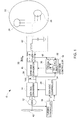
- FIG. 1 shows a conventional grid connected wind power generating system 10.
- the system includes a wind generator 12, a generator side converter 14, and a grid side converter 16.
- the system further includes a grid side controller 18, a generator side controller 20, and a power grid 22.
- Power grid 22 typically includes conventional synchronous generators 24 and electrical loads 26.
- a resonant circuit 42 is also formed in power grid 22.
- a direct current (DC) link 28 connects generator side converter 14 and grid side converter 16.
- Generator side converter 14 converts alternating current (AC) power generated by wind generator 12 into DC power.
- Grid side converter 16 then converts the DC power to AC power at a frequency compatible with power grid 22.
- grid side controller 18 controls the phase and amplitude of the output current 30 of grid side converter 16 relative to the measured terminal voltage (Vpcc).
- grid side controller 18 and grid side converter 16 may alternatively function as a voltage controlled source.
- Grid side controller 18 typically includes a phase locked loop (PLL) 32, a DC voltage regulator 34, and an AC current regulator 36.
- PLL 32 senses three phase voltages of the power grid and generates a frequency and phase reference for grid side converter 16.
- DC voltage regulator 34 helps in maintaining the DC link voltage at a desired value.
- Current regulator 36 generates the output current reference for grid side converter 16 based on the PLL output and the DC voltage regulator output.
- Generator side controller 20 generates operating or switching signals for generator side converter 14.
- a turbine controller 38 provides a torque reference to generator side controller 20 based on wind velocity or rotor speed of the wind turbine. The turbine controller generates the torque reference to maximize the energy captured from the wind.
- Grid resonance modes can couple to grid side controller 18 through the voltage and current measurement signals.
- the grid side control of DC voltage can be susceptible to interaction with weak grids or grid resonant modes. This interaction may occur due to the effect of weak or resonant grid conditions on the forward loop transfer function of the DC link voltage control.
- generator side converter 14 controls DC link voltage
- grid side converter 16 controls wind turbine torque.
- this type of control may result in wind turbine torque instability due to the effect of weak or resonant grid conditions on the forward loop transfer function of the torque control.
- FIG. 2 shows a grid connected wind power generating system 60 in accordance with an embodiment of the present invention.
- Power generating system 60 includes a unified controller 62 that coordinates the control of signals necessary for the transfer of power from the wind turbine generator 12 to the converter DC link 28 and power grid 22.
- the unified controller functions may include, but are not limited to, controlling output power, generator torque, generator speed, and DC link voltage.
- unified controller 62 includes a torque controller 80 and a voltage controller 82. It should be noted that torque controller 80 may be replaced by or supplemented with other controllers to control parameters of generating systems such as active power, generator speed, or output current.
- unified controller 62 includes a coupled or a multivariable controller that receives torque reference command T*, torque feedback signal T, DC link voltage reference command Vdc*, and DC link voltage feedback signal Vdc. The controller 62 then provides control signals or switching commands 66 and 68 to generator side converter 14 and grid side converter 16, respectively.
- the torque control and the DC link voltage control functions are split between generator side and grid side converters in a parsing controller 81 based on various strategies such as parsing the control signals based on frequency response or based on amplitudes, for example.
- FIG. 3 shows a detailed block diagram of the unified controller 62 of FIG. 2 in accordance with an embodiment of the present invention.
- Unified controller 62 includes torque controller 80, DC link voltage controller 82, and dynamic parsing controller 81. Both torque and DC link voltage controllers 80, 82 may comprise proportional-integral (PI) type controllers.
- Torque controller 80 receives the torque reference command T* and the torque feedback signal T and generates a torque control signal r1 based on a difference between T* and T.
- voltage controller 82 generates a voltage control signal r2 based on a difference between reference DC link voltage command Vdc* and DC link voltage feedback signal Vdc.
- dynamic parsing controller 81 includes function blocks 84, 86 for torque control and function blocks 88, 90 for voltage control to parse the torque and voltage control signals r1 and r2 between the generator side converter and the grid side converter in response to system dynamics. In this way, the control and disturbance response of the torque and DC link voltage signals will be improved.
- function blocks 84, 86, 88, 90 may be dynamic, linear, or nonlinear scalar blocks, or combinations of these. Further, the parameters of the function blocks may be dynamically adjusted based on other control signals such as output power, generator speed, voltage magnitude, or current magnitude.
- Function blocks 84, 86, 88, 90 may parse the torque and voltage control signals r1 and r2 based on any of a number of strategies.
- One strategy is to parse the signals based on frequency response such that high frequency and low frequency signals are separated.
- the high frequency and low frequency signals may be defmed by the operator and, in one embodiment, low frequency signals refer to signals of bandwidth lower than 5 or 10 Hz, and high frequency signals refer to signals with bandwidth higher than 5 or 10 Hz.
- the operator as used herein refers to an authorized person who controls the operation of a power generating system and has authority to control parameters of the controllers.
- function blocks 86 and 88 may comprise high pass filters
- function blocks 84 and 90 may comprise low pass filters.
- s is a Laplace operator
- T, k 11 , and k 21 are constants determined based on network elements and network conditions such as power level, voltage and current magnitude, faults, or generator speed.
- constants T, k 11 , and k 21 are dynamic and may vary depending on system conditions.
- T may comprise a time constant determined from the parsing frequency bandwidth selected. Thus, this implementation will parse control based on the frequency content of the voltage control signal.
- the high frequency content of the signal (freq > 1/2 ⁇ T) will be directed to the generator side converter 14, and the low frequency (e.g., steady-state) content will be directed to the grid side converter 16.
- Similar transfer functions may be used for control blocks 84 and 86 for controlling the torque.
- the frequency parsed signals r11 and r2h from the torque control signal and the voltage control signal are then combined to generate an active-current signal Ir_gen for the generator side converter 14. Further, frequency parsed signals r1h and r21 are combined to generate an active-current signal Ir_grid for the grid side converter 16.
- This implementation will parse control signals based on the amplitude of the torque control signal r1 and voltage control signal r2. For example, signals between F max and F min will affect only the grid side converter, while signals outside of F max and F min will affect the gen side converter.
- F max and F min are again dynamic constants and are determined based on network elements and network conditions such as power level, voltage and current magnitude, faults, and generator speed.
- function blocks 84, 86, 88, and 90 given in equations 1, 2, 3, and 4 are just for exemplary purposes and in one embodiment, function block 84 may have unity gain, function block 86 may have zero gain, function block 88 may be a high pass filter and function block 90 may be a low pass filter. Similarly in another embodiment, function blocks 84, 86 may parse the signal based on frequency response whereas function blocks 88, 90 may parse the signal based on amplitude of the control signal. In yet another embodiment, where a third converter with an energy storage device or a load and a respective controller is used in the system, the control signals may be parsed in three different components. Thus, various different combinations may be used for implementation of function blocks 84, 86, 88, and 90.
- FIG. 4 shows simulated frequency responses 100 and 102 of function blocks 84 and 86 or 88 and 90 in accordance with an embodiment of the present invention.
- horizontal axis 104 represents frequency in Hz
- vertical axis 106 represents amplitude gain in decibel (db).
- db decibel
- the function blocks 84 and 86 or 88 and 90 parse the control signals between two frequencies and control the grid side converter and the generator side converter.
- the frequency x Hz may be determined by the operator, and in one embodiment it may be 5 Hz or 10 Hz. In another embodiment, the frequency is determined based on the sub synchronous resonance frequency.
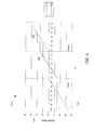
- FIG. 5 shows a simulated amplitude response plot 120 of function blocks 88, 90 for the implementation described in equations (3) and (4).
- horizontal axis 122 represents the amplitude of voltage control signal r2
- vertical axis 124 represents the amplitude of response signals r2h and r21.
- Plot 126 represents response signal r2h of function block 88
- plot 128 represents response signal r21 of function block 90 respectively. It can be seen from plots 126 and 128 that the voltage control signal r2 is parsed based on a lower cut off amplitude Fmin and a upper cut off amplitude Fmax as described in equations (3) and (4).
- control system can provide a more stable control behavior for weak or resonant grid networks by dynamically directing the control signals to the more stable converter platform, depending on system conditions.
- control method can also be used in other uncontrollable power generating systems connected to the power grid such as photovoltaic, microturbines, marine hydrokinetic, and fuel cell systems.
- the grid side and the generator side converter controls may be implemented as a coupled or multivariable control.
- control method may also split the control signal in more than two components.
- torque control and DC-link voltage control can be split between the generator side and the grid side based on several strategies.
Landscapes
- Engineering & Computer Science (AREA)
- Power Engineering (AREA)
- Control Of Eletrric Generators (AREA)
- Inverter Devices (AREA)
- Control Of Electrical Variables (AREA)
- Supply And Distribution Of Alternating Current (AREA)
Abstract
Description
- The present invention relates generally to power generating systems connected to a grid and, more particularly, to control of a wind power generating system.
- Wind turbine generators are regarded as environmentally friendly and relatively inexpensive alternative sources of energy that utilize wind energy to produce electrical power. A wind turbine generator generally includes a wind rotor having turbine blades that transform wind energy into rotational motion of a drive shaft, which in turn is utilized to drive a rotor of an electrical generator to produce electrical power. Modem wind power generation systems typically take the form of a wind-farm having multiple such wind turbine generators that are operable to supply power to a utility system.
- Some wind turbine generators have a variable frequency operation and require a variable frequency power electronic converter to interface the wind turbine generator output with the utility grid. In one common approach, the wind turbine generator output is directly fed to a power electronic converter where the generator output frequency is rectified and inverted into a fixed frequency as needed by the utility system.
- One of the challenges associated with such systems is control of wind turbines in the event of a weak and/or resonant grid connection. For example, to compensate for a weak grid connection use of series compensation, such as a series capacitor bank, is one means of increasing transmission capability in the grid, but this has potential limitation. Series compensation may lead to sub-synchronous resonance modes that can couple to the power electronic converter controllers causing control instability. Resonant mode coupling challenges may also occur at super synchronous frequencies due to the interaction of distributed shunt capacitance and line inductance in the network.
- Therefore, it is desirable to determine a method and a system that will address the foregoing issues.
- In accordance with an embodiment of the present invention, a power generation system including an energy source coupled to a DC link through a first power converter is provided. The power generation system also includes a second power converter for coupling the DC link to a power grid, a first controller for regulating voltage on the DC link and a second controller for regulating a parameter of the energy source. The system further includes a dynamic parsing controller coupled to the first power converter and the second power converter and configured to selectively parse the output signals of the first and second controllers and generate operating commands for the first and the second power converters based at least in part on the parsed output signals.
- In accordance with another embodiment of the present invention, a control system for a wind power generating system including a wind turbine coupled to a DC link through a first power converter and a second power converter for coupling the DC link to a power grid is provided. The control system includes a DC link controller for regulating voltage on the DC link and a torque controller for regulating torque of the wind turbine. The control system further includes a dynamic parsing controller coupled to the first power converter and the second power converter and configured to selectively parse the output signals of the torque and DC link controllers and generate operating commands for the first and second power converters based at least in part on the parse output signals.
- In accordance with yet another embodiment of the present invention, a method of supplying electrical power to a power grid is provided. The method includes generating the electrical power from an electrical source and coupling the electrical source to the power grid through a first power converter and a second power converter. The method also includes controlling the first and second power converters by interfacing output signals of a first controller configured to regulate voltage on the DC link and a second controller configured to regulate a parameter of the energy source.
- These and other features, aspects, and advantages of the present invention will become better understood when the following detailed description is read with reference to the accompanying drawings in which like characters represent like parts throughout the drawings, wherein:
-
FIG. 1 is a diagrammatical representation of a conventional wind power generating system connected to a power grid; -
FIG. 2 is a diagrammatical representation of a grid connected wind power generating system, in accordance with an embodiment of the present invention; -
FIG. 3 is a diagrammatical representation of a detailed block diagram of an unified controller ofFIG. 2 , in accordance with an embodiment of the present invention; -
FIG. 4 is graphical representation of frequency responses of function blocks ofFIG. 3 ; and -
FIG. 5 is graphical representation of an amplitude response plot of function blocks ofFIG. 3 . - As discussed in detail below, embodiments of the present invention function to provide methods and systems to control grid connected power generating systems. Although the present discussion focuses on control of power electronic converters in a wind power generating system, the present invention is applicable to any power generating system with a dispatchable or intermittent input energy source and a power electronic converter interface. For example, the present invention is also applicable but not limited to solar power generation, marine hydrokinetic power generation, microturbines, and fuel cell systems.
-
FIG. 1 shows a conventional grid connected windpower generating system 10. The system includes awind generator 12, agenerator side converter 14, and agrid side converter 16. The system further includes agrid side controller 18, agenerator side controller 20, and apower grid 22.Power grid 22 typically includes conventionalsynchronous generators 24 andelectrical loads 26. Aresonant circuit 42 is also formed inpower grid 22. A direct current (DC)link 28 connectsgenerator side converter 14 andgrid side converter 16.Generator side converter 14 converts alternating current (AC) power generated bywind generator 12 into DC power.Grid side converter 16 then converts the DC power to AC power at a frequency compatible withpower grid 22. - The combination of
grid side controller 18 andgrid side converter 16 functions as a current controlled source forgrid 22. In other words,grid side controller 18 controls the phase and amplitude of theoutput current 30 ofgrid side converter 16 relative to the measured terminal voltage (Vpcc). In one embodiment,grid side controller 18 andgrid side converter 16 may alternatively function as a voltage controlled source.Grid side controller 18 typically includes a phase locked loop (PLL) 32, aDC voltage regulator 34, and anAC current regulator 36.PLL 32 senses three phase voltages of the power grid and generates a frequency and phase reference forgrid side converter 16.DC voltage regulator 34 helps in maintaining the DC link voltage at a desired value.Current regulator 36 generates the output current reference forgrid side converter 16 based on the PLL output and the DC voltage regulator output.Generator side controller 20 generates operating or switching signals forgenerator side converter 14. In one embodiment, aturbine controller 38 provides a torque reference togenerator side controller 20 based on wind velocity or rotor speed of the wind turbine. The turbine controller generates the torque reference to maximize the energy captured from the wind. - Grid resonance modes can couple to
grid side controller 18 through the voltage and current measurement signals. In some embodiments, the grid side control of DC voltage can be susceptible to interaction with weak grids or grid resonant modes. This interaction may occur due to the effect of weak or resonant grid conditions on the forward loop transfer function of the DC link voltage control. In another embodiment (not shown inFIG. 1 ) to overcome control instability problems caused by weak or resonant grid conditions,generator side converter 14 controls DC link voltage,grid side converter 16 controls wind turbine torque. However, this type of control may result in wind turbine torque instability due to the effect of weak or resonant grid conditions on the forward loop transfer function of the torque control. -
FIG. 2 shows a grid connected windpower generating system 60 in accordance with an embodiment of the present invention.Power generating system 60 includes aunified controller 62 that coordinates the control of signals necessary for the transfer of power from thewind turbine generator 12 to theconverter DC link 28 andpower grid 22. The unified controller functions may include, but are not limited to, controlling output power, generator torque, generator speed, and DC link voltage. In one embodiment, unifiedcontroller 62 includes atorque controller 80 and avoltage controller 82. It should be noted thattorque controller 80 may be replaced by or supplemented with other controllers to control parameters of generating systems such as active power, generator speed, or output current. - In one specific embodiment, unified
controller 62 includes a coupled or a multivariable controller that receives torque reference command T*, torque feedback signal T, DC link voltage reference command Vdc*, and DC link voltage feedback signal Vdc. Thecontroller 62 then provides control signals orswitching commands generator side converter 14 andgrid side converter 16, respectively. In one embodiment, the torque control and the DC link voltage control functions are split between generator side and grid side converters in aparsing controller 81 based on various strategies such as parsing the control signals based on frequency response or based on amplitudes, for example. -
FIG. 3 shows a detailed block diagram of theunified controller 62 ofFIG. 2 in accordance with an embodiment of the present invention.Unified controller 62 includestorque controller 80, DClink voltage controller 82, anddynamic parsing controller 81. Both torque and DClink voltage controllers Torque controller 80 receives the torque reference command T* and the torque feedback signal T and generates a torque control signal r1 based on a difference between T* and T. Similarly,voltage controller 82 generates a voltage control signal r2 based on a difference between reference DC link voltage command Vdc* and DC link voltage feedback signal Vdc. - In one embodiment,
dynamic parsing controller 81 includes function blocks 84, 86 for torque control and function blocks 88, 90 for voltage control to parse the torque and voltage control signals r1 and r2 between the generator side converter and the grid side converter in response to system dynamics. In this way, the control and disturbance response of the torque and DC link voltage signals will be improved. In one embodiment, function blocks 84, 86, 88, 90 may be dynamic, linear, or nonlinear scalar blocks, or combinations of these. Further, the parameters of the function blocks may be dynamically adjusted based on other control signals such as output power, generator speed, voltage magnitude, or current magnitude. - Function blocks 84, 86, 88, 90 may parse the torque and voltage control signals r1 and r2 based on any of a number of strategies. One strategy is to parse the signals based on frequency response such that high frequency and low frequency signals are separated. For example, the high frequency and low frequency signals may be defmed by the operator and, in one embodiment, low frequency signals refer to signals of bandwidth lower than 5 or 10 Hz, and high frequency signals refer to signals with bandwidth higher than 5 or 10 Hz. The operator as used herein refers to an authorized person who controls the operation of a power generating system and has authority to control parameters of the controllers. In one embodiment function blocks 86 and 88 may comprise high pass filters, and function blocks 84 and 90 may comprise low pass filters. The transfer functions F12(s) and F22(s) of the function blocks 88, 90 for the DC-link voltage control may be given as


where s is a Laplace operator, and T, k11, and k21 are constants determined based on network elements and network conditions such as power level, voltage and current magnitude, faults, or generator speed. In one embodiment, constants T, k11, and k21 are dynamic and may vary depending on system conditions. For example, T may comprise a time constant determined from the parsing frequency bandwidth selected. Thus, this implementation will parse control based on the frequency content of the voltage control signal. The high frequency content of the signal (freq > 1/2πT) will be directed to thegenerator side converter 14, and the low frequency (e.g., steady-state) content will be directed to thegrid side converter 16. Similar transfer functions may be used for control blocks 84 and 86 for controlling the torque. The frequency parsed signals r11 and r2h from the torque control signal and the voltage control signal are then combined to generate an active-current signal Ir_gen for thegenerator side converter 14. Further, frequency parsed signals r1h and r21 are combined to generate an active-current signal Ir_grid for thegrid side converter 16. - In another embodiment, based on system conditions, function blocks 88, 90 for dc-link voltage control may be designed as below:


- This implementation will parse control signals based on the amplitude of the torque control signal r1 and voltage control signal r2. For example, signals between Fmax and Fmin will affect only the grid side converter, while signals outside of Fmax and Fmin will affect the gen side converter. Fmax and Fmin are again dynamic constants and are determined based on network elements and network conditions such as power level, voltage and current magnitude, faults, and generator speed.
- It should be noted that the implementations of function blocks 84, 86, 88, and 90 given in
equations function block 84 may have unity gain,function block 86 may have zero gain,function block 88 may be a high pass filter andfunction block 90 may be a low pass filter. Similarly in another embodiment, function blocks 84, 86 may parse the signal based on frequency response whereas function blocks 88, 90 may parse the signal based on amplitude of the control signal. In yet another embodiment, where a third converter with an energy storage device or a load and a respective controller is used in the system, the control signals may be parsed in three different components. Thus, various different combinations may be used for implementation of function blocks 84, 86, 88, and 90. -
FIG. 4 shows simulatedfrequency responses responses horizontal axis 104 represents frequency in Hz, andvertical axis 106 represents amplitude gain in decibel (db). It can be seen fromresponse 100 that below a frequency of x Hz the amplitude gain is below 3 db, and beyond that the amplitude gain is 0 db. On the contrary, forresponse 102, the amplitude gain is below 3 db for frequencies above x Hz. Thus, the function blocks 84 and 86 or 88 and 90 parse the control signals between two frequencies and control the grid side converter and the generator side converter. It should be noted that the frequency x Hz may be determined by the operator, and in one embodiment it may be 5 Hz or 10 Hz. In another embodiment, the frequency is determined based on the sub synchronous resonance frequency. -
FIG. 5 shows a simulatedamplitude response plot 120 of function blocks 88, 90 for the implementation described in equations (3) and (4). Inplot 120,horizontal axis 122 represents the amplitude of voltage control signal r2, andvertical axis 124 represents the amplitude of response signals r2h and r21.Plot 126 represents response signal r2h offunction block 88, andplot 128 represents response signal r21 offunction block 90 respectively. It can be seen fromplots - One of the advantages of the present control system is that it can provide a more stable control behavior for weak or resonant grid networks by dynamically directing the control signals to the more stable converter platform, depending on system conditions. As will be appreciated by those of ordinary skill in the art, even though the above discussion focuses on wind power generating system, the control method can also be used in other uncontrollable power generating systems connected to the power grid such as photovoltaic, microturbines, marine hydrokinetic, and fuel cell systems. In such power generating systems, the grid side and the generator side converter controls may be implemented as a coupled or multivariable control. Similarly, even though the discussion focuses on parsing the signals in two components, in certain embodiments where more than two power converters or two controllers are utilized, the control method may also split the control signal in more than two components. Further, torque control and DC-link voltage control can be split between the generator side and the grid side based on several strategies.
- For the sake of completeness, various aspects of the invention are set out in the following numbered clauses:
- 1. A power generating system comprising
an energy source coupled to a DC link through a first power converter;
a second power converter for coupling the DC link to a power grid;
a first controller configured to regulate voltage on the DC-link;
a second controller configured to regulate a parameter of the energy source;
a dynamic parsing controller coupled to the first power converter and the second power converter and configured to selectively parse the output signals of the first and second controllers and generate operating commands for the first and second power converters based at least in part on the parsed output signals. - 2. The system of
clause 1, wherein the energy source comprises at least one of a wind turbine, photovoltaic module, microturbine, marine hydrokinetic energy device, or fuel cell. - 3. The system of
clause 1, wherein the parameter of the energy source comprises at least one of an active power, generator torque, output current, or generator speed. - 4. The system of
clause 1, wherein the dynamic parsing controller comprises a single multivariable controller. - 5. The system of
clause 1, wherein the dynamic parsing controller comprises function blocks configured to parse output signals of the first controller and the second controller. - 6. The system of
clause 5, wherein the function blocks parse output signals based on frequency response, amplitudes, or combinations thereof. - 7. The system of
clause 5, wherein function blocks comprise dynamic functions, linear functions, nonlinear functions, or combinations thereof. - 8. The system of
clause 7, wherein parameters of function blocks are based on at least one of a network condition, output power, voltage magnitude, current magnitude, or generator speed. - 9. The system of
clause 5, wherein function blocks comprise a high pass filter and a low pass filter for parsing the output signals into high frequency and low frequency components. - 10. The system of
clause 9, wherein frequencies for high pass filter and low pass filters are determined by a system operator. - 11. The system of
clause 9, wherein the low frequency component comprises signals below 10 Hz and the high frequency component comprises signals above 10 Hz. - 12. A control system for a wind power generating system comprising a wind turbine coupled to a DC link through a first power converter and a second power converter for coupling the DC link to a power grid, the control system comprising:
- a DC link controller configured to regulate voltage on the DC-link;
- a torque controller configured to regulate torque of the wind turbine;
- a dynamic parsing controller coupled to the first power converter and the second power converter and configured to selectively parse the output signals of the torque and DC link controllers and generate operating commands for the first and second power converters based at least in part on the parsed output signals.
- 13. The control system of
clause 12 wherein the dynamic parsing controller is configured so as to send operating commands to both the first and second power converters to regulate the voltage on the DC-link - 14. The control system of
clause 12 wherein the dynamic parsing controller is configured so as to send operating commands to both the first and second power converters to regulate the torque of the wind turbine. - 15. The control system of
clause 12, wherein the dynamic parsing controller comprises function blocks configured to parse output signals of the first controller and the second controller. - 16. The control system of clause 15, wherein the function blocks parse output signals based on frequency of output signals, amplitudes of output signals, or combinations thereof.
- 17. The control system of clause 15, wherein parameters of function blocks are based on at least one of a network condition, output power, voltage magnitude, current magnitude, or generator speed.
- 18. A method of supplying electrical power to a power grid comprising:
- generating the electrical power from an electrical source;
- coupling the electrical source to the power grid through a first power converter and a second power converter;
- controlling the first and second power converters by interfacing output signals of a first controller configured to regulate voltage on the DC-link and a second controller configured to regulate a parameter of the energy source.
- 19. The method of
clause 18, wherein interfacing output signals comprises parsing output signals based on frequency response, amplitudes, or combinations thereof. - 20. The method of clause 19, wherein the output signals are parsed in a high frequency component and a low frequency component.
Claims (15)
- A power generating system comprising
an energy source coupled to a DC link through a first power converter;
a second power converter for coupling the DC link to a power grid;
a first controller configured to regulate voltage on the DC-link;
a second controller configured to regulate a parameter of the energy source;
a dynamic parsing controller coupled to the first power converter and the second power converter and configured to selectively parse the output signals of the first and second controllers and generate operating commands for the first and second power converters based at least in part on the parsed output signals. - The system of claim 1, wherein the energy source comprises at least one of a wind turbine, photovoltaic module, microturbine, marine hydrokinetic energy device, or fuel cell, and the parameter of the energy source comprises at least one of an active power, generator torque, output current, or generator speed.
- The system of claim 1 or claim 2, wherein the dynamic parsing controller comprises a single multivariable controller which comprises function blocks configured to parse output signals of the first controller and the second controller.
- The system of claim 3, wherein the function blocks parse output signals based on frequency response, amplitudes, or combinations thereof, and the function blocks comprise dynamic functions, linear functions, nonlinear functions, or combinations thereof.
- The system of claim 4, wherein parameters of function blocks are based on at least one of a network condition, output power, voltage magnitude, current magnitude, or generator speed.
- The system of claim 3, wherein function blocks comprise a high pass filter and a low pass filter for parsing the output signals into high frequency and low frequency components.
- The system of claim 6, wherein frequencies for high pass filter and low pass filters are determined by a system operator.
- The system of claim 7, wherein the low frequency component comprises signals below 10 Hz and the high frequency component comprises signals above 10 Hz.
- A control system for a wind power generating system comprising a wind turbine coupled to a DC link through a first power converter and a second power converter for coupling the DC link to a power grid, the control system comprising:a DC link controller configured to regulate voltage on the DC-link;a torque controller configured to regulate torque of the wind turbine;a dynamic parsing controller coupled to the first power converter and the second power converter and configured to selectively parse the output signals of the torque and DC link controllers and generate operating commands for the first and second power converters based at least in part on the parsed output signals.
- The control system of claim 9, wherein the dynamic parsing controller is configured so as to send operating commands to both the first and second power converters to regulate the voltage on the DC-link
- The control system of claim 9, wherein the dynamic parsing controller is configured so as to send operating commands to both the first and second power converters to regulate the torque of the wind turbine.
- The control system of claim 9, wherein the dynamic parsing controller comprises function blocks configured to parse output signals of the first controller and the second controller.
- The control system of claim 12, wherein the function blocks parse output signals based on frequency of output signals, amplitudes of output signals, or combinations thereof.
- The control system of claim 12, wherein parameters of function blocks are based on at least one of a network condition, output power, voltage magnitude, current magnitude, or generator speed.
- A method of supplying electrical power to a power grid comprising:generating the electrical power from an electrical source;coupling the electrical source to the power grid through a first power converter and a second power converter;controlling the first and second power converters by interfacing output signals of a first controller configured to regulate voltage on the DC-link and a second controller configured to regulate a parameter of the energy source.
Applications Claiming Priority (1)
| Application Number | Priority Date | Filing Date | Title |
|---|---|---|---|
| US12/966,269 US8174150B2 (en) | 2010-12-13 | 2010-12-13 | System and method for control of a grid connected power generating system |
Publications (3)
| Publication Number | Publication Date |
|---|---|
| EP2463997A2 true EP2463997A2 (en) | 2012-06-13 |
| EP2463997A3 EP2463997A3 (en) | 2017-08-30 |
| EP2463997B1 EP2463997B1 (en) | 2020-09-30 |
Family
ID=44559286
Family Applications (1)
| Application Number | Title | Priority Date | Filing Date |
|---|---|---|---|
| EP11191651.6A Active EP2463997B1 (en) | 2010-12-13 | 2011-12-02 | System and method for control of a grid connected power generating system |
Country Status (5)
| Country | Link |
|---|---|
| US (1) | US8174150B2 (en) |
| EP (1) | EP2463997B1 (en) |
| CN (1) | CN102570498B (en) |
| DK (1) | DK2463997T3 (en) |
| ES (1) | ES2840998T3 (en) |
Families Citing this family (11)
| Publication number | Priority date | Publication date | Assignee | Title |
|---|---|---|---|---|
| EP2528184B1 (en) * | 2011-05-25 | 2014-09-10 | Siemens Aktiengesellschaft | Method and apparatus for controlling a DC-transmission link |
| CN103220369A (en) * | 2012-01-19 | 2013-07-24 | 北京华电信通科技有限公司 | Information interaction interface and method between household appliances and smart grid |
| CN104854784B (en) * | 2012-12-06 | 2018-06-26 | 维斯塔斯风力系统集团公司 | Three-phase AC electrical systems and the method for compensating the inductance unbalance in such system |
| US10199863B2 (en) | 2014-10-29 | 2019-02-05 | Solarcity Corporation | Dynamic curtailment of an energy generation system |
| EP3241270B1 (en) | 2014-12-30 | 2021-06-30 | Vestas Wind Systems A/S | Dc-link reference voltage determination for wind turbine converter systems |
| EP3070807B1 (en) * | 2015-03-19 | 2020-09-09 | General Electric Technology GmbH | Power transmission network |
| US12362566B2 (en) * | 2016-09-19 | 2025-07-15 | Flexgen Power Systems, Llc | Systems and methods for rapid activation and synchronization of dispatchable power sources |
| US9806690B1 (en) * | 2016-09-30 | 2017-10-31 | AEP Transmission Holding Company, LLC | Subsynchronous oscillation relay |
| CN111355257A (en) * | 2018-12-24 | 2020-06-30 | 哈尔滨工业大学 | Passive quasi-PR control method for photovoltaic grid-connected inverter under weak grid |
| WO2020200378A1 (en) * | 2019-04-04 | 2020-10-08 | Vestas Wind Systems A/S | Control of a wind turbine using split power reference signals |
| US10985611B2 (en) | 2019-04-10 | 2021-04-20 | General Electric Company | System and method for estimating grid strength |
Family Cites Families (11)
| Publication number | Priority date | Publication date | Assignee | Title |
|---|---|---|---|---|
| US5083039B1 (en) * | 1991-02-01 | 1999-11-16 | Zond Energy Systems Inc | Variable speed wind turbine |
| JPH0638537A (en) * | 1992-07-13 | 1994-02-10 | Nippon Electric Ind Co Ltd | Pwm inverter with variable gain adaptive control function |
| US6850426B2 (en) | 2002-04-30 | 2005-02-01 | Honeywell International Inc. | Synchronous and bi-directional variable frequency power conversion systems |
| GB0523087D0 (en) * | 2005-11-11 | 2005-12-21 | Alstom Power Conversion Ltd | Power converters |
| CN101926085A (en) | 2008-01-24 | 2010-12-22 | 欧陆汽车系统美国有限公司 | multi-level switching power supply |
| US8373312B2 (en) | 2008-01-31 | 2013-02-12 | General Electric Company | Solar power generation stabilization system and method |
| DE102008034532A1 (en) * | 2008-02-20 | 2009-08-27 | Repower Systems Ag | Wind turbine with inverter control |
| US7884588B2 (en) | 2008-04-10 | 2011-02-08 | Stmicroelectronics S.R.L. | Control method and device for a system of interleaved converters using a designated master converter |
| US7804184B2 (en) * | 2009-01-23 | 2010-09-28 | General Electric Company | System and method for control of a grid connected power generating system |
| US8587160B2 (en) * | 2009-09-04 | 2013-11-19 | Rockwell Automation Technologies, Inc. | Grid fault ride-through for current source converter-based wind energy conversion systems |
| CN101640423B (en) * | 2009-09-08 | 2011-11-16 | 西安交通大学 | Generator system for wind power generation and variable speed control method |
-
2010
- 2010-12-13 US US12/966,269 patent/US8174150B2/en active Active
-
2011
- 2011-12-02 EP EP11191651.6A patent/EP2463997B1/en active Active
- 2011-12-02 ES ES11191651T patent/ES2840998T3/en active Active
- 2011-12-02 DK DK11191651.6T patent/DK2463997T3/en active
- 2011-12-13 CN CN201110436558.0A patent/CN102570498B/en active Active
Non-Patent Citations (1)
| Title |
|---|
| None |
Also Published As
| Publication number | Publication date |
|---|---|
| US20110221280A1 (en) | 2011-09-15 |
| EP2463997B1 (en) | 2020-09-30 |
| CN102570498A (en) | 2012-07-11 |
| DK2463997T3 (en) | 2021-01-11 |
| US8174150B2 (en) | 2012-05-08 |
| EP2463997A3 (en) | 2017-08-30 |
| CN102570498B (en) | 2016-03-09 |
| ES2840998T3 (en) | 2021-07-07 |
Similar Documents
| Publication | Publication Date | Title |
|---|---|---|
| EP2463997B1 (en) | System and method for control of a grid connected power generating system | |
| US9528499B2 (en) | Power oscillation damping controller | |
| Li et al. | Control of DFIG wind turbine with direct-current vector control configuration | |
| US8994200B2 (en) | Power system frequency inertia for power generation system | |
| Li et al. | Coordinated control of wind farm and VSC–HVDC system using capacitor energy and kinetic energy to improve inertia level of power systems | |
| US9677544B2 (en) | Power plant generation system, method for controlling wind turbine generators, power plant controller and wind turbine generator | |
| CN105917542B (en) | Wind power plant, wind farm, method for operating the wind power plant, and control and/or regulation device | |
| Koutiva et al. | Optimal integration of an offshore wind farm to a weak AC grid | |
| US10907613B2 (en) | Damping mechanical oscillations of a wind turbine | |
| US10731633B2 (en) | Power generation stabilization control systems and methods | |
| EP3460943A1 (en) | Power generation system, system for suppressing sub-synchronous oscillations, and method for controlling operation of power system | |
| Albasheri et al. | Control and power management of DC microgrid based wind/battery/supercapacitor | |
| Ogundairo et al. | Online adaptive damping controller architecture for wind integrated power grid | |
| Shair et al. | New-type power system stabilizers (NPSS) for damping wideband oscillations in converter-dominated power systems | |
| RU2696604C1 (en) | Method for compensation of currents to be supplied from wind power park | |
| JP2011055591A (en) | Inverter control circuit and grid-connected inverter system with the same | |
| CN110556842B (en) | Control method of direct-drive wind power plant inductive weak grid-connected subsynchronous oscillation suppression device | |
| Renjit | Modeling, analysis and control of mixed source microgrid | |
| McGill et al. | Generator response following as a primary frequency response control strategy for VSC-HVDC connected offshore wind farms | |
| Gupta et al. | Real time implementation of droop controlled wind DFIG system | |
| Bidadfar et al. | Droop-based frequency support from offshore hvdc grids | |
| Dey et al. | Fuzzy-based Coordinated Control to Reduce DC-link Overvoltage of a PMSG based Wind Energy Systems during Grid Faults | |
| Huang et al. | A unified grid-forming structure with power control capability for DFIG wind turbines | |
| Tian et al. | Influence of Filter Inductance on Synchronization Stability of Grid-Connected Converter | |
| Duan et al. | Adaptive control strategy for direct-drive wind turbine and energy storage to actively support grid voltage |
Legal Events
| Date | Code | Title | Description |
|---|---|---|---|
| PUAI | Public reference made under article 153(3) epc to a published international application that has entered the european phase |
Free format text: ORIGINAL CODE: 0009012 |
|
| AK | Designated contracting states |
Kind code of ref document: A2 Designated state(s): AL AT BE BG CH CY CZ DE DK EE ES FI FR GB GR HR HU IE IS IT LI LT LU LV MC MK MT NL NO PL PT RO RS SE SI SK SM TR |
|
| AX | Request for extension of the european patent |
Extension state: BA ME |
|
| PUAL | Search report despatched |
Free format text: ORIGINAL CODE: 0009013 |
|
| AK | Designated contracting states |
Kind code of ref document: A3 Designated state(s): AL AT BE BG CH CY CZ DE DK EE ES FI FR GB GR HR HU IE IS IT LI LT LU LV MC MK MT NL NO PL PT RO RS SE SI SK SM TR |
|
| AX | Request for extension of the european patent |
Extension state: BA ME |
|
| RIC1 | Information provided on ipc code assigned before grant |
Ipc: H02P 9/10 20060101ALI20170726BHEP Ipc: H02M 5/458 20060101AFI20170726BHEP Ipc: H02J 3/38 20060101ALI20170726BHEP |
|
| STAA | Information on the status of an ep patent application or granted ep patent |
Free format text: STATUS: REQUEST FOR EXAMINATION WAS MADE |
|
| 17P | Request for examination filed |
Effective date: 20180228 |
|
| RBV | Designated contracting states (corrected) |
Designated state(s): AL AT BE BG CH CY CZ DE DK EE ES FI FR GB GR HR HU IE IS IT LI LT LU LV MC MK MT NL NO PL PT RO RS SE SI SK SM TR |
|
| GRAP | Despatch of communication of intention to grant a patent |
Free format text: ORIGINAL CODE: EPIDOSNIGR1 |
|
| STAA | Information on the status of an ep patent application or granted ep patent |
Free format text: STATUS: GRANT OF PATENT IS INTENDED |
|
| INTG | Intention to grant announced |
Effective date: 20200421 |
|
| RIN1 | Information on inventor provided before grant (corrected) |
Inventor name: DELMERICO, ROBERT WILLIAM Inventor name: LARSEN, EINAR VAUGHN |
|
| GRAS | Grant fee paid |
Free format text: ORIGINAL CODE: EPIDOSNIGR3 |
|
| GRAA | (expected) grant |
Free format text: ORIGINAL CODE: 0009210 |
|
| STAA | Information on the status of an ep patent application or granted ep patent |
Free format text: STATUS: THE PATENT HAS BEEN GRANTED |
|
| AK | Designated contracting states |
Kind code of ref document: B1 Designated state(s): AL AT BE BG CH CY CZ DE DK EE ES FI FR GB GR HR HU IE IS IT LI LT LU LV MC MK MT NL NO PL PT RO RS SE SI SK SM TR |
|
| REG | Reference to a national code |
Ref country code: GB Ref legal event code: FG4D Ref country code: CH Ref legal event code: EP |
|
| REG | Reference to a national code |
Ref country code: AT Ref legal event code: REF Ref document number: 1319831 Country of ref document: AT Kind code of ref document: T Effective date: 20201015 |
|
| REG | Reference to a national code |
Ref country code: DE Ref legal event code: R096 Ref document number: 602011068758 Country of ref document: DE |
|
| REG | Reference to a national code |
Ref country code: IE Ref legal event code: FG4D |
|
| REG | Reference to a national code |
Ref country code: DK Ref legal event code: T3 Effective date: 20210106 |
|
| PG25 | Lapsed in a contracting state [announced via postgrant information from national office to epo] |
Ref country code: GR Free format text: LAPSE BECAUSE OF FAILURE TO SUBMIT A TRANSLATION OF THE DESCRIPTION OR TO PAY THE FEE WITHIN THE PRESCRIBED TIME-LIMIT Effective date: 20201231 Ref country code: BG Free format text: LAPSE BECAUSE OF FAILURE TO SUBMIT A TRANSLATION OF THE DESCRIPTION OR TO PAY THE FEE WITHIN THE PRESCRIBED TIME-LIMIT Effective date: 20201230 Ref country code: NO Free format text: LAPSE BECAUSE OF FAILURE TO SUBMIT A TRANSLATION OF THE DESCRIPTION OR TO PAY THE FEE WITHIN THE PRESCRIBED TIME-LIMIT Effective date: 20201230 Ref country code: SE Free format text: LAPSE BECAUSE OF FAILURE TO SUBMIT A TRANSLATION OF THE DESCRIPTION OR TO PAY THE FEE WITHIN THE PRESCRIBED TIME-LIMIT Effective date: 20200930 Ref country code: HR Free format text: LAPSE BECAUSE OF FAILURE TO SUBMIT A TRANSLATION OF THE DESCRIPTION OR TO PAY THE FEE WITHIN THE PRESCRIBED TIME-LIMIT Effective date: 20200930 Ref country code: FI Free format text: LAPSE BECAUSE OF FAILURE TO SUBMIT A TRANSLATION OF THE DESCRIPTION OR TO PAY THE FEE WITHIN THE PRESCRIBED TIME-LIMIT Effective date: 20200930 |
|
| REG | Reference to a national code |
Ref country code: AT Ref legal event code: MK05 Ref document number: 1319831 Country of ref document: AT Kind code of ref document: T Effective date: 20200930 |
|
| PG25 | Lapsed in a contracting state [announced via postgrant information from national office to epo] |
Ref country code: LV Free format text: LAPSE BECAUSE OF FAILURE TO SUBMIT A TRANSLATION OF THE DESCRIPTION OR TO PAY THE FEE WITHIN THE PRESCRIBED TIME-LIMIT Effective date: 20200930 Ref country code: RS Free format text: LAPSE BECAUSE OF FAILURE TO SUBMIT A TRANSLATION OF THE DESCRIPTION OR TO PAY THE FEE WITHIN THE PRESCRIBED TIME-LIMIT Effective date: 20200930 |
|
| REG | Reference to a national code |
Ref country code: NL Ref legal event code: MP Effective date: 20200930 |
|
| REG | Reference to a national code |
Ref country code: LT Ref legal event code: MG4D |
|
| PG25 | Lapsed in a contracting state [announced via postgrant information from national office to epo] |
Ref country code: LT Free format text: LAPSE BECAUSE OF FAILURE TO SUBMIT A TRANSLATION OF THE DESCRIPTION OR TO PAY THE FEE WITHIN THE PRESCRIBED TIME-LIMIT Effective date: 20200930 Ref country code: PT Free format text: LAPSE BECAUSE OF FAILURE TO SUBMIT A TRANSLATION OF THE DESCRIPTION OR TO PAY THE FEE WITHIN THE PRESCRIBED TIME-LIMIT Effective date: 20210201 Ref country code: NL Free format text: LAPSE BECAUSE OF FAILURE TO SUBMIT A TRANSLATION OF THE DESCRIPTION OR TO PAY THE FEE WITHIN THE PRESCRIBED TIME-LIMIT Effective date: 20200930 Ref country code: RO Free format text: LAPSE BECAUSE OF FAILURE TO SUBMIT A TRANSLATION OF THE DESCRIPTION OR TO PAY THE FEE WITHIN THE PRESCRIBED TIME-LIMIT Effective date: 20200930 Ref country code: SM Free format text: LAPSE BECAUSE OF FAILURE TO SUBMIT A TRANSLATION OF THE DESCRIPTION OR TO PAY THE FEE WITHIN THE PRESCRIBED TIME-LIMIT Effective date: 20200930 Ref country code: CZ Free format text: LAPSE BECAUSE OF FAILURE TO SUBMIT A TRANSLATION OF THE DESCRIPTION OR TO PAY THE FEE WITHIN THE PRESCRIBED TIME-LIMIT Effective date: 20200930 Ref country code: EE Free format text: LAPSE BECAUSE OF FAILURE TO SUBMIT A TRANSLATION OF THE DESCRIPTION OR TO PAY THE FEE WITHIN THE PRESCRIBED TIME-LIMIT Effective date: 20200930 |
|
| PG25 | Lapsed in a contracting state [announced via postgrant information from national office to epo] |
Ref country code: PL Free format text: LAPSE BECAUSE OF FAILURE TO SUBMIT A TRANSLATION OF THE DESCRIPTION OR TO PAY THE FEE WITHIN THE PRESCRIBED TIME-LIMIT Effective date: 20200930 Ref country code: IS Free format text: LAPSE BECAUSE OF FAILURE TO SUBMIT A TRANSLATION OF THE DESCRIPTION OR TO PAY THE FEE WITHIN THE PRESCRIBED TIME-LIMIT Effective date: 20210130 Ref country code: AL Free format text: LAPSE BECAUSE OF FAILURE TO SUBMIT A TRANSLATION OF THE DESCRIPTION OR TO PAY THE FEE WITHIN THE PRESCRIBED TIME-LIMIT Effective date: 20200930 Ref country code: AT Free format text: LAPSE BECAUSE OF FAILURE TO SUBMIT A TRANSLATION OF THE DESCRIPTION OR TO PAY THE FEE WITHIN THE PRESCRIBED TIME-LIMIT Effective date: 20200930 |
|
| PG25 | Lapsed in a contracting state [announced via postgrant information from national office to epo] |
Ref country code: SK Free format text: LAPSE BECAUSE OF FAILURE TO SUBMIT A TRANSLATION OF THE DESCRIPTION OR TO PAY THE FEE WITHIN THE PRESCRIBED TIME-LIMIT Effective date: 20200930 |
|
| REG | Reference to a national code |
Ref country code: DE Ref legal event code: R097 Ref document number: 602011068758 Country of ref document: DE |
|
| REG | Reference to a national code |
Ref country code: ES Ref legal event code: FG2A Ref document number: 2840998 Country of ref document: ES Kind code of ref document: T3 Effective date: 20210707 |
|
| REG | Reference to a national code |
Ref country code: CH Ref legal event code: PL |
|
| PLBE | No opposition filed within time limit |
Free format text: ORIGINAL CODE: 0009261 |
|
| STAA | Information on the status of an ep patent application or granted ep patent |
Free format text: STATUS: NO OPPOSITION FILED WITHIN TIME LIMIT |
|
| GBPC | Gb: european patent ceased through non-payment of renewal fee |
Effective date: 20201230 |
|
| PG25 | Lapsed in a contracting state [announced via postgrant information from national office to epo] |
Ref country code: MC Free format text: LAPSE BECAUSE OF FAILURE TO SUBMIT A TRANSLATION OF THE DESCRIPTION OR TO PAY THE FEE WITHIN THE PRESCRIBED TIME-LIMIT Effective date: 20200930 |
|
| REG | Reference to a national code |
Ref country code: BE Ref legal event code: MM Effective date: 20201231 |
|
| 26N | No opposition filed |
Effective date: 20210701 |
|
| PG25 | Lapsed in a contracting state [announced via postgrant information from national office to epo] |
Ref country code: LU Free format text: LAPSE BECAUSE OF NON-PAYMENT OF DUE FEES Effective date: 20201202 Ref country code: FR Free format text: LAPSE BECAUSE OF NON-PAYMENT OF DUE FEES Effective date: 20201231 Ref country code: IE Free format text: LAPSE BECAUSE OF NON-PAYMENT OF DUE FEES Effective date: 20201202 Ref country code: IT Free format text: LAPSE BECAUSE OF FAILURE TO SUBMIT A TRANSLATION OF THE DESCRIPTION OR TO PAY THE FEE WITHIN THE PRESCRIBED TIME-LIMIT Effective date: 20200930 |
|
| PG25 | Lapsed in a contracting state [announced via postgrant information from national office to epo] |
Ref country code: SI Free format text: LAPSE BECAUSE OF FAILURE TO SUBMIT A TRANSLATION OF THE DESCRIPTION OR TO PAY THE FEE WITHIN THE PRESCRIBED TIME-LIMIT Effective date: 20200930 Ref country code: LI Free format text: LAPSE BECAUSE OF NON-PAYMENT OF DUE FEES Effective date: 20201231 Ref country code: GB Free format text: LAPSE BECAUSE OF NON-PAYMENT OF DUE FEES Effective date: 20201230 Ref country code: CH Free format text: LAPSE BECAUSE OF NON-PAYMENT OF DUE FEES Effective date: 20201231 |
|
| PG25 | Lapsed in a contracting state [announced via postgrant information from national office to epo] |
Ref country code: IS Free format text: LAPSE BECAUSE OF FAILURE TO SUBMIT A TRANSLATION OF THE DESCRIPTION OR TO PAY THE FEE WITHIN THE PRESCRIBED TIME-LIMIT Effective date: 20210130 Ref country code: TR Free format text: LAPSE BECAUSE OF FAILURE TO SUBMIT A TRANSLATION OF THE DESCRIPTION OR TO PAY THE FEE WITHIN THE PRESCRIBED TIME-LIMIT Effective date: 20200930 Ref country code: MT Free format text: LAPSE BECAUSE OF FAILURE TO SUBMIT A TRANSLATION OF THE DESCRIPTION OR TO PAY THE FEE WITHIN THE PRESCRIBED TIME-LIMIT Effective date: 20200930 Ref country code: CY Free format text: LAPSE BECAUSE OF FAILURE TO SUBMIT A TRANSLATION OF THE DESCRIPTION OR TO PAY THE FEE WITHIN THE PRESCRIBED TIME-LIMIT Effective date: 20200930 |
|
| PG25 | Lapsed in a contracting state [announced via postgrant information from national office to epo] |
Ref country code: MK Free format text: LAPSE BECAUSE OF FAILURE TO SUBMIT A TRANSLATION OF THE DESCRIPTION OR TO PAY THE FEE WITHIN THE PRESCRIBED TIME-LIMIT Effective date: 20200930 |
|
| PG25 | Lapsed in a contracting state [announced via postgrant information from national office to epo] |
Ref country code: BE Free format text: LAPSE BECAUSE OF NON-PAYMENT OF DUE FEES Effective date: 20201231 |
|
| P01 | Opt-out of the competence of the unified patent court (upc) registered |
Effective date: 20230530 |
|
| REG | Reference to a national code |
Ref country code: DE Ref legal event code: R082 Ref document number: 602011068758 Country of ref document: DE Representative=s name: ZIMMERMANN & PARTNER PATENTANWAELTE MBB, DE Ref country code: DE Ref legal event code: R082 Ref document number: 602011068758 Country of ref document: DE Ref country code: DE Ref legal event code: R081 Ref document number: 602011068758 Country of ref document: DE Owner name: GENERAL ELECTRIC RENOVABLES ESPANA, S.L., ES Free format text: FORMER OWNER: GENERAL ELECTRIC CO., SCHENECTADY, N.Y., US |
|
| REG | Reference to a national code |
Ref country code: DE Ref legal event code: R082 Ref document number: 602011068758 Country of ref document: DE Representative=s name: ZIMMERMANN & PARTNER PATENTANWAELTE MBB, DE |
|
| REG | Reference to a national code |
Ref country code: ES Ref legal event code: PC2A Owner name: GENERAL ELECTRIC RENOVABLES ESPANA S.L. Effective date: 20240809 |
|
| PGFP | Annual fee paid to national office [announced via postgrant information from national office to epo] |
Ref country code: DE Payment date: 20251126 Year of fee payment: 15 |
|
| PGFP | Annual fee paid to national office [announced via postgrant information from national office to epo] |
Ref country code: DK Payment date: 20251119 Year of fee payment: 15 |
|
| PGFP | Annual fee paid to national office [announced via postgrant information from national office to epo] |
Ref country code: ES Payment date: 20260102 Year of fee payment: 15 |