EP2463883A1 - Device for detecting a loss of vacuum in a vacuum cutting device and vacuum cutting device comprising such a device - Google Patents
Device for detecting a loss of vacuum in a vacuum cutting device and vacuum cutting device comprising such a device Download PDFInfo
- Publication number
- EP2463883A1 EP2463883A1 EP11354049A EP11354049A EP2463883A1 EP 2463883 A1 EP2463883 A1 EP 2463883A1 EP 11354049 A EP11354049 A EP 11354049A EP 11354049 A EP11354049 A EP 11354049A EP 2463883 A1 EP2463883 A1 EP 2463883A1
- Authority
- EP
- European Patent Office
- Prior art keywords
- vacuum
- band
- value
- strip
- electrode
- Prior art date
- Legal status (The legal status is an assumption and is not a legal conclusion. Google has not performed a legal analysis and makes no representation as to the accuracy of the status listed.)
- Granted
Links
- 239000000919 ceramic Substances 0.000 claims abstract description 14
- 238000001514 detection method Methods 0.000 claims abstract description 12
- 239000011810 insulating material Substances 0.000 claims abstract description 7
- 239000007787 solid Substances 0.000 claims abstract description 5
- 239000004020 conductor Substances 0.000 claims description 14
- 239000003990 capacitor Substances 0.000 claims description 10
- 230000011664 signaling Effects 0.000 claims description 9
- 238000001465 metallisation Methods 0.000 claims description 6
- 239000011368 organic material Substances 0.000 claims description 3
- 230000001052 transient effect Effects 0.000 claims description 3
- 238000004061 bleaching Methods 0.000 claims 1
- 230000005347 demagnetization Effects 0.000 claims 1
- 239000002184 metal Substances 0.000 abstract 1
- 238000005259 measurement Methods 0.000 description 5
- 239000003708 ampul Substances 0.000 description 4
- 239000004593 Epoxy Substances 0.000 description 3
- 230000006870 function Effects 0.000 description 3
- 239000000463 material Substances 0.000 description 3
- 238000010586 diagram Methods 0.000 description 2
- 238000009825 accumulation Methods 0.000 description 1
- 230000008878 coupling Effects 0.000 description 1
- 238000010168 coupling process Methods 0.000 description 1
- 238000005859 coupling reaction Methods 0.000 description 1
- 230000007423 decrease Effects 0.000 description 1
- 238000002845 discoloration Methods 0.000 description 1
- 238000009413 insulation Methods 0.000 description 1
- 230000037452 priming Effects 0.000 description 1
- 230000035945 sensitivity Effects 0.000 description 1
- 239000011800 void material Substances 0.000 description 1
Images


Classifications
-
- H—ELECTRICITY
- H01—ELECTRIC ELEMENTS
- H01H—ELECTRIC SWITCHES; RELAYS; SELECTORS; EMERGENCY PROTECTIVE DEVICES
- H01H33/00—High-tension or heavy-current switches with arc-extinguishing or arc-preventing means
- H01H33/60—Switches wherein the means for extinguishing or preventing the arc do not include separate means for obtaining or increasing flow of arc-extinguishing fluid
- H01H33/66—Vacuum switches
- H01H33/668—Means for obtaining or monitoring the vacuum
-
- H—ELECTRICITY
- H01—ELECTRIC ELEMENTS
- H01H—ELECTRIC SWITCHES; RELAYS; SELECTORS; EMERGENCY PROTECTIVE DEVICES
- H01H9/00—Details of switching devices, not covered by groups H01H1/00 - H01H7/00
- H01H9/54—Circuit arrangements not adapted to a particular application of the switching device and for which no provision exists elsewhere
-
- H—ELECTRICITY
- H01—ELECTRIC ELEMENTS
- H01H—ELECTRIC SWITCHES; RELAYS; SELECTORS; EMERGENCY PROTECTIVE DEVICES
- H01H33/00—High-tension or heavy-current switches with arc-extinguishing or arc-preventing means
- H01H33/02—Details
- H01H33/59—Circuit arrangements not adapted to a particular application of the switch and not otherwise provided for, e.g. for ensuring operation of the switch at a predetermined point in the ac cycle
Definitions
- the present invention relates to a device for detecting the loss of vacuum in a vacuum cut-off apparatus, said apparatus being located in a powered electrical primary network and having an envelope comprising a first portion of substantially cylindrical shape made at least partly of a insulating material such as ceramic, said first part being closed at its two opposite ends by two bottoms, said envelope housing a fixed electrode integral with one of the aforesaid funds and supporting a fixed contact, and a movable electrode supporting a movable contact, said movable electrode being slidably mounted through the other of the two bottoms, between a closed position of the apparatus in which the movable contact is in contact with the fixed contact and an open position of the apparatus in which the movable contact is separated from the fixed contact, as well as a vacuum breaking device comprising such a device.
- the dielectric strength in the bulb is such that almost all of the voltage is between the electrode and the screen.
- the gas that has entered the bulb reduces the dielectric strength inside the bulb and ignitions occur between the electrodes and the screen.
- the current flowing in the electrical circuit connecting the electrodes in series to the floating screen is then measured, the measured current being an image of the state of the vacuum inside the bulb.
- this device is limited to bulbs having a floating screen inside.
- this type of detector is not usable.
- the present invention solves this drawback and proposes a device for detecting the loss of vacuum in a vacuum interrupter such as a bulb, of simple design, and which can be applied both in floating screen bulbs and in asymmetric bulbs by example.
- the subject of the present invention is a device for detecting the loss of vacuum of the kind mentioned above, this device being characterized in that said envelope comprises a second part made of an insulating material and placed at least partly around said first portion, said second portion having on at least a portion of its outer surface a layer of a conductive material electrically connected to the ground forming a shield, in that a so-called first band of said layer of conductive material is isolated from the remainder of said layer, this so-called first band being situated opposite, on the one hand, of the first insulating part and, on the other hand, of the fixed electrode or of the mobile electrode, this so-called first forming band a capacity consisting of two capacitors in series, respectively a so-called vacuum capacity, situated between the mobile or fixed electrode and the inner face of the first e insulating part, and a capacitance called solids, interposed between the inner face of the aforementioned first insulating part and the so-called first band, and means for measuring the current flowing in the so-called first band
- said vacuum breaking apparatus comprising a screen electrically connected to the mobile or fixed electrode and partially surrounding the mobile or fixed electrode, this apparatus is characterized in that inside the layer of material aforementioned conductor, a second band of conductive material is isolated from the rest of the aforementioned conductive layer and also from the first aforementioned band, this second band being located opposite said screen and forming between the so-called second band and said screen, a so-called third capacitance said third said capacitance being dimensioned in such a way that its value is equal to the value of said two said first and second capacitances connected in series, and means for measuring the voltage between the two bands, the changing the value of the vacuum capacity caused by a vacuum loss inside the apparatus causing a change in the value of the current flowing in the first band, this difference between the two current values causing a differential voltage between the two bands, and signaling means of a certain differential voltage value.
- the width of the so-called first band is at most 20 mm, so that the value of the current measured across the first band in case of leakage is about 10 ⁇ A for a signal / signal ratio. noise of 10 dB.
- said apparatus comprising a first screen electrically connected to the mobile or fixed electrode and a second screen electrically connected to the fixed or mobile electrode, said screens surrounding at least partially the mobile or respectively fixed electrode, said apparatus is characterized in that within said conductive material layer, a second strip and a third strip of conductive material are isolated from the remainder of said conductive layer and also said first strip, said second and third strips being respectively located opposite said first and second screens and forming, on the one hand, between the so-called second band and said first screen and, on the other hand, between said third band and said second screen respectively a so-called third capacity and said capacity.
- so-called third and fourth capabilities being dimensioned in such a way that ue their value is equal to the value of the two aforesaid said first and second capacitances connected in series, in that the so-called second and third bands are electrically connected at the same point where the so-called second and third currents flowing in these two bands add, to give a so-called fourth current, and means for measuring the differential voltage generated by the difference between two current values respectively said fourth said current and said first current flowing in the first band.
- the width of the so-called first band is set so that the value of the current measured across the first band is greater than 16 ⁇ A for a signal / noise ratio of 20 dB.
- this apparatus comprises an electronic circuit controlled by the aforementioned differential voltage and controlling signaling means of a certain differential voltage value, said differential voltage value being representative of a loss of vacuum inside the the vacuum interrupter.
- each of these two bands is electrically connected to the Earth by an impedance, across which impedances, an impedance circuit comprising a differential switch is connected.
- the aforementioned signaling means comprise a differential switch and / or a fuse and / or a detonator and / or a means for demagnetizing a magnet and / or a means for discoloring a conductive strip of organic material.
- the electronic circuit comprises an accumulation charging circuit which is slow enough not to react to transient overvoltages in the primary electrical network, but which is fast enough to act in the hours or the day following the loss. empty.
- Another subject of the present invention is a vacuum interrupter comprising a device for detecting the loss of vacuum comprising the previously mentioned characteristics taken alone or in combination.
- this vacuum interrupter is a vacuum interrupter.
- this bulb is housed in a casing overmolded by an insulating material, the outer surface of the overmoulded portion of the casing being metallized, said metallization layer being grounded and constituting a shielding.
- the present invention also relates to a vacuum interrupter further comprising a floating screen mounted around the electrodes and contacts, said bulb comprising a vacuum loss detection device comprising the aforementioned features taken alone or in combination, of the type comprising only one band.
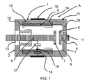
- a vacuum interrupter A comprising, in a manner known per se, an envelope 1 of substantially cylindrical shape closed by two bottoms 2,3.
- the envelope encloses an electrode 4 fixed with respect to said envelope, and an electrode 5 movable relative to said envelope, the two electrodes 4,5 each supporting at their free end respectively a fixed contact 6 and a movable contact 7, said electrode mobile 5 being movable between a contact position of the two contacts 6.7 and a position separated from the two contacts.
- the casing 1 comprises a cylindrical portion 8 made of ceramic closed by two end covers 9,10 crossed respectively by the aforementioned two electrodes 4,5, said electrodes being supported respectively by two extensions 11,12.
- the bulb 1 also comprises two electrically conductive screens 13, 13 for the one 13, the mobile electrode 5 and the other 14 for the fixed electrode 4, these screens being located at the junction between the end caps 9,10 and the insulating ceramic part 8 of the casing.
- the assembly consisting of the ceramic portion 8, the end caps 9,10 and the interfaces 2,3 at least in part, is overmolded by an epoxy material 26 to achieve a reinforced insulation of said casing.
- the outer portion of the overmolded epoxy portion is metallized and this metallization is grounded so as to form a shield.
- the left and right interfaces 2, 3 are non-metallized surfaces and serve as an interface with other equipment items not shown here.
- a first band 16 of cylindrical shape is isolated from the rest of the metallized surface 15.
- This first band 16 forms a capacitor composed of two capacitors in series 17, 18. Firstly, a first void capacity 17, placed between the movable electrode 5 and the inner face 19 of the ceramic part 8, and a capacity 18 called solids, placed between the inner face 19 of the part ceramic 8 and the so-called first insulated metallization strip 16.
- a bulb according to a second embodiment of the invention as shown in the figure 2 solves this problem.
- the bulb A comprises the same elements as those already described in the previous embodiment, but a second strip 20 of a layer of the metallization 15 is isolated from the rest of the metallized surface.
- This second band 20 is located around that 13 of the above-mentioned conductive screens 13, 14 which is located on the opposite side to the fixed electrode 4, and which is therefore electrically connected to the moving electrode 5.
- This second band 20 creates a capacitance Said third between said strip 20 and said screen 13 electrically connected to the movable electrode 5.
- This capacity 25 is dimensioned such that its value is equal to the value of the capacity constituted by the two capacities 17, 18 in series.
- Each of these two strips 16,20 is electrically connected to earth T (to be indicated in the figures) by an impedance 29,30 here represented by a capacitor.
- an impedance circuit 21 comprising a differential switch 22 is connected.
- a differential voltage is created between the two strips 16,20 across these impedances 29,30. This voltage is zero or close to zero in the case of a good vacuum state inside the bulb because the currents flowing in the two strips 16,20 are almost identical.
- the electronic circuit 21 contains a trickle charging circuit which is slow enough not to react to transient overvoltages in the primary power grid, but which is fast enough to act in the hours or the day following the loss of vacuum.
- This period is less than the duration of the ignition inside the bulb that depends on the size of the leak, as shown on the figure 3 illustrating the evolution of the pressure 32 as a function of time, the duration of which is of the order of 2 to 20 days.
- a thyristor discharges the energy in a differential switch in order to cause a change of state that will keep in memory the loss of vacuum bulb even if it is no longer fed by the primary network.
- this differential measurement makes it possible to separate the information related to the mains voltage from those related to the state of the vacuum in the bulb in order to exclusively measure a signal related to the loss of vacuum in the bulb.
- the first signal 23 represents the differential voltage across the impedances 29,30 due to the temporary passage of the bulb in the area of low dielectric strength in which are produced internal priming for 2 to 20 days.
- the second signal 24 represents the change of state of the differential switch where the state 0 represents the closed position and the state 1 represents the open position, which change of state will be visible at any time after.
- This detection device makes it possible to give a visibility of the state of the bulb during the intervention with the equipment even in the absence of voltage of both the primary network of the bulb and the secondary network in the station .
- first strip 16 should be placed facing the ceramic part 8 and facing the moving electrode 5 or the fixed electrode 4.
- the second strip 20, for its part, should be located opposite the one of the conductive screens 13, 14 and therefore of either the moving electrode 5 or the fixed electrode 4.
- the second band 20 must be in front of the screen connected to the moving electrode.
- the second band 20 exerts a compensation of the signal in the absence of a leak in the closed position of the contacts, that is to say that in this case, the currents flowing in the two strips are substantially identical, as illustrated in FIG. figure 5 in position 2.
- a differential voltage is observed, which means that it is difficult to distinguish between these two cases and the presence of a leak when the contacts are closed (position 1).
- the second band 20 overcompensates the capacitive current in the first band 16, while for case 4 corresponding to an open position of the movable contact without contact power supply mobile, the second band no longer receives current because of the lack of capacitive coupling with the fixed contact.
- the width of the first band so that it does not exceed 20mm, to obtain a signal with a current value of 10 ⁇ A approximately for a Signal / Noise ratio of 10dB. This makes it possible to improve the selectivity to the detriment of the signal. Below 20 mm, the nuisance will be less than -10 dB for a signal close to 10 ⁇ A as illustrated on the figure 6 .
- the curve a represents the signal in ⁇ A as a function of the width of the first band in mm
- the curves b and c respectively represent the ratios Noise / Signal in case of open mobile contact with a power supply only. mobile contact or fixed contact, and this depending on the width of the first band.
- the bulb comprises a first measurement band 16 situated substantially in the center, facing the ceramic part 8 and the moving electrode 5, a second strip 20 separated from conductive material, surrounding the first screen 13 electrically connected to the mobile electrode, and a third strip 27 of conductive material, disposed on the side of the fixed contact 4, surrounding the second screen 14 electrically connected to the fixed electrode 4.
- this third band 27 it is formed between said third band 27 and the second screen 14, a fourth capacitor 28.
- This band makes it possible to compensate for the spurious signals caused by the small capacitor 33, between the first band 16 and the screen 14.
- the so-called third 25 and fourth 28 capacitors are dimensioned in such a way that the total capacity value they form, being connected in parallel, is equal to the capacity value formed by the set constituted by the two capacitors 17, 18 connected in series, these two capacities 17,18 being connected in parallel with the capacitor 33.
- the aforementioned second and third strips are electrically connected at one and the same point, where the so-called second and third currents flowing respectively in these two bands add up to give a so-called fourth current.
- the device then comprises means for measuring the differential voltage between the current flowing in the first band, says first, and the current says fourth aforesaid. This differential voltage can then feed an electronic circuit as described in the previous embodiment, which circuit will actuate signaling means.
- the advantage of this third band is to improve the measurement sensitivity in the case where the contacts 6 and 7 are open and a primary voltage is applied on the fixed contact side 6.
- the width of the strips will preferably be chosen so that the value of the signal current is greater than 16 ⁇ A for a Signal / Noise ratio of 20 dB.
- a signal compensation will be obtained even in cases where the movable contact is open or the fixed contact is open in the bulb.
- the detection of a differential voltage of a certain value will be representative of a leak inside the bulb.
- This device is applicable to any type of bulb comprising an envelope comprising a ceramic part or any material having similar dielectric characteristics.
- this device is applicable to bulbs such as floating-screen type bulbs, the first band to be placed facing the ceramic and facing the mobile or fixed electrode.
- differential switch may be replaced by other devices that make it possible to display a change of state such as a fuse or a detonator, a means of demagnetizing a magnet such as a Mi-top, and a means of discoloration of a conductive strip of organic material, ...
Landscapes
- Measuring Fluid Pressure (AREA)
Abstract
Description
La présente invention concerne un dispositif de détection de la perte de vide dans un appareil de coupure à vide, ledit appareil étant situé dans un réseau primaire électrique alimenté et comportant une enveloppe comportant une première partie de forme sensiblement cylindrique réalisée au moins en partie en un matériau isolant tel la céramique, ladite première partie étant fermée à ses deux extrémités opposées par deux fonds, ladite enveloppe logeant une électrode fixe solidaire de l'un des fonds précités et supportant un contact fixe, et une électrode mobile supportant un contact mobile, ladite électrode mobile étant montée coulissante à travers l'autre des deux fonds, entre une position fermée de l'appareil dans laquelle le contact mobile est en contact avec le contact fixe et une position ouverte de l'appareil dans laquelle le contact mobile est séparé du contact fixe, ainsi qu'un appareil de coupure à vide comportant un tel dispositif.The present invention relates to a device for detecting the loss of vacuum in a vacuum cut-off apparatus, said apparatus being located in a powered electrical primary network and having an envelope comprising a first portion of substantially cylindrical shape made at least partly of a insulating material such as ceramic, said first part being closed at its two opposite ends by two bottoms, said envelope housing a fixed electrode integral with one of the aforesaid funds and supporting a fixed contact, and a movable electrode supporting a movable contact, said movable electrode being slidably mounted through the other of the two bottoms, between a closed position of the apparatus in which the movable contact is in contact with the fixed contact and an open position of the apparatus in which the movable contact is separated from the fixed contact, as well as a vacuum breaking device comprising such a device.
On connaît le document
Si l'état du vide est correct, la tenue diélectrique dans l'ampoule est telle que la quasi-totalité de la tension se trouve entre l'électrode et l'écran.If the state of the vacuum is correct, the dielectric strength in the bulb is such that almost all of the voltage is between the electrode and the screen.
Si la qualité du vide est mauvaise, le gaz qui est entré dans l'ampoule réduit la tenue diélectrique à l'intérieur de l'ampoule et des amorçages se produisent entre les électrodes et l'écran. On mesure alors le courant qui circule dans le circuit électrique reliant les électrodes en série à l'écran flottant, le courant mesuré étant une image de l'état du vide à l'intérieur de l'ampoule.If the vacuum quality is poor, the gas that has entered the bulb reduces the dielectric strength inside the bulb and ignitions occur between the electrodes and the screen. The current flowing in the electrical circuit connecting the electrodes in series to the floating screen is then measured, the measured current being an image of the state of the vacuum inside the bulb.
L'application de ce dispositif se limite aux ampoules ayant un écran flottant à l'intérieur. Pour les autres ampoules, telles les ampoules dites asymétriques dépourvues d'un écran flottant, ce type de détecteur n'est pas utilisable.The application of this device is limited to bulbs having a floating screen inside. For other bulbs, such as asymmetrical bulbs without a floating screen, this type of detector is not usable.
La présente invention résout cet inconvénient et propose un dispositif de détection de la perte de vide dans un appareil de coupure à vide tel une ampoule, de conception simple, et pouvant être appliqué aussi bien dans des ampoules à écran flottant que dans les ampoules asymétriques par exemple.The present invention solves this drawback and proposes a device for detecting the loss of vacuum in a vacuum interrupter such as a bulb, of simple design, and which can be applied both in floating screen bulbs and in asymmetric bulbs by example.
A cet effet, la présente invention a pour objet un dispositif de détection de la perte de vide du genre précédemment mentionné, ce dispositif étant caractérisé en ce que ladite enveloppe comporte une seconde partie réalisée en un matériau isolant et placée au moins en partie autour de la première partie précitée, cette seconde partie comportant sur au moins une partie de sa surface extérieure, une couche d'un matériau conducteur reliée électriquement à la terre formant un blindage, en ce qu'une bande dite première de cette couche de matériau conducteur est isolée du reste de ladite couche, cette bande dite première étant située en regard d'une part, de la première partie isolante et d'autre part, soit de l'électrode fixe, soit de l'électrode mobile, cette bande dite première formant une capacité composée de deux capacités en série, respectivement une capacité dite du vide, située entre l'électrode mobile ou fixe et la face intérieure de la première partie isolante, et une capacité dite des solides, interposée entre la face intérieure de la première partie isolante précitée et la bande dite première, et des moyens de mesure du courant circulant dans la bande dite première reliés à des moyens de signalisation, une certaine valeur de changement de la valeur du courant traduisant un changement de valeur de la capacité du vide, lequel changement traduisant une perte de vide à l'intérieur de l'appareil de coupure à vide.For this purpose, the subject of the present invention is a device for detecting the loss of vacuum of the kind mentioned above, this device being characterized in that said envelope comprises a second part made of an insulating material and placed at least partly around said first portion, said second portion having on at least a portion of its outer surface a layer of a conductive material electrically connected to the ground forming a shield, in that a so-called first band of said layer of conductive material is isolated from the remainder of said layer, this so-called first band being situated opposite, on the one hand, of the first insulating part and, on the other hand, of the fixed electrode or of the mobile electrode, this so-called first forming band a capacity consisting of two capacitors in series, respectively a so-called vacuum capacity, situated between the mobile or fixed electrode and the inner face of the first e insulating part, and a capacitance called solids, interposed between the inner face of the aforementioned first insulating part and the so-called first band, and means for measuring the current flowing in the so-called first band connected to signaling means, some value of change of the value of the current translating a change of value of the vacuum capacity, which change translating a loss of vacuum inside the vacuum cutoff apparatus.
Selon une autre caractéristique, ledit appareil de coupure à vide comportant un écran relié électriquement à l'électrode mobile ou fixe et entourant partiellement l'électrode mobile ou fixe, cet appareil est caractérisée en ce qu'à l'intérieur de la couche de matériau conducteur précité, une seconde bande de matériau conducteur est isolée du reste de la couche conductrice précitée et également de la première bande précitée, cette seconde bande étant située en regard dudit écran et formant entre la bande dite seconde et ledit écran, une capacité dite troisième, ladite capacité dite troisième étant dimensionnée de telle manière que sa valeur soit égale à la valeur des deux capacités dites première et seconde précitées reliées en série, et des moyens pour mesurer la tension entre les deux bandes, le changement de la valeur de la capacité du vide entraînée par une perte de vide à l'intérieur de l'appareil entraînant un changement de la valeur du courant circulant dans la première bande, cette différence entre les deux valeurs de courant entraînant une tension différentielle entre les deux bandes, et des moyens de signalisation d'une certaine valeur de tension différentielle.According to another characteristic, said vacuum breaking apparatus comprising a screen electrically connected to the mobile or fixed electrode and partially surrounding the mobile or fixed electrode, this apparatus is characterized in that inside the layer of material aforementioned conductor, a second band of conductive material is isolated from the rest of the aforementioned conductive layer and also from the first aforementioned band, this second band being located opposite said screen and forming between the so-called second band and said screen, a so-called third capacitance said third said capacitance being dimensioned in such a way that its value is equal to the value of said two said first and second capacitances connected in series, and means for measuring the voltage between the two bands, the changing the value of the vacuum capacity caused by a vacuum loss inside the apparatus causing a change in the value of the current flowing in the first band, this difference between the two current values causing a differential voltage between the two bands, and signaling means of a certain differential voltage value.
Selon une caractéristique particulière de cette réalisation, la largeur de la bande dite première est au plus de 20 mm, de manière que la valeur du courant mesurée aux bornes de la première bande en cas de fuite soit d'environ 10µA pour un ratio signal/bruit de 10 dB.According to a particular characteristic of this embodiment, the width of the so-called first band is at most 20 mm, so that the value of the current measured across the first band in case of leakage is about 10 μA for a signal / signal ratio. noise of 10 dB.
Selon une autre réalisation, ledit appareil comportant un premier écran relié électriquement à l'électrode mobile ou fixe et un second écran relié électriquement à l'électrode fixe ou mobile, lesdits écrans entourant au moins partiellement l'électrode mobile ou respectivement fixe, ledit appareil est caractérisée en ce qu'à l'intérieur de la couche de matériau conducteur précité, une seconde bande et une troisième bande de matériau conducteur sont isolées du reste de la couche conductrice précitée et également de la première bande précitée, ces seconde et troisième bandes étant situées respectivement en regard desdits premier et second écrans et formant d'une part, entre la bande dite seconde et ledit premier écran et d'autre part, entre la bande dite troisième et ledit second écran respectivement une capacité dite troisième et une capacité dite quatrième, lesdites capacités dite troisième et quatrième étant dimensionnées de telle manière que leur valeur soit égale à la valeur des deux capacités dites première et seconde précitées reliées en série, en ce que les bandes dites seconde et troisième sont reliées électriquement en un même point où les courants dits second et troisième circulant dans ces deux bandes s'additionnent, pour donner un courant dit quatrième, et des moyens pour mesurer la tension différentielle engendrée par la différence entre deux valeurs de courant respectivement le courant dit quatrième précité et le courant dit premier circulant dans la première bande.According to another embodiment, said apparatus comprising a first screen electrically connected to the mobile or fixed electrode and a second screen electrically connected to the fixed or mobile electrode, said screens surrounding at least partially the mobile or respectively fixed electrode, said apparatus is characterized in that within said conductive material layer, a second strip and a third strip of conductive material are isolated from the remainder of said conductive layer and also said first strip, said second and third strips being respectively located opposite said first and second screens and forming, on the one hand, between the so-called second band and said first screen and, on the other hand, between said third band and said second screen respectively a so-called third capacity and said capacity. fourth, said so-called third and fourth capabilities being dimensioned in such a way that ue their value is equal to the value of the two aforesaid said first and second capacitances connected in series, in that the so-called second and third bands are electrically connected at the same point where the so-called second and third currents flowing in these two bands add, to give a so-called fourth current, and means for measuring the differential voltage generated by the difference between two current values respectively said fourth said current and said first current flowing in the first band.
Selon une caractéristique particulière, la largeur de la bande dite première est réglée de manière que la valeur du courant mesuré aux bornes de la première bande soit supérieure à 16 µA pour un ratio Signal/Bruit de 20dB.According to a particular characteristic, the width of the so-called first band is set so that the value of the current measured across the first band is greater than 16 μA for a signal / noise ratio of 20 dB.
Selon une autre caractéristique, cet appareil comporte un circuit électronique commandé par la tension différentielle précitée et commandant des moyens de signalisation d'une certaine valeur de tension différentielle, ladite valeur de tension différentielle étant représentative d'une perte de vide à l'intérieur de l'appareil de coupure à vide.According to another characteristic, this apparatus comprises an electronic circuit controlled by the aforementioned differential voltage and controlling signaling means of a certain differential voltage value, said differential voltage value being representative of a loss of vacuum inside the the vacuum interrupter.
Selon une autre caractéristique, chacune de ces deux bandes est reliée électriquement à la Terre par une impédance, aux bornes desquelles impédances, un circuit à impédance comportant un interrupteur différentiel est relié.According to another characteristic, each of these two bands is electrically connected to the Earth by an impedance, across which impedances, an impedance circuit comprising a differential switch is connected.
Selon une caractéristique particulière, les moyens de signalisation précités comportent un interrupteur différentiel et/ou un fusible et/ou un détonateur et/ou un moyen de démagnétisation d'un aimant et/ou un moyen de décoloration d'une bande conductrice de matière organique.According to one particular characteristic, the aforementioned signaling means comprise a differential switch and / or a fuse and / or a detonator and / or a means for demagnetizing a magnet and / or a means for discoloring a conductive strip of organic material. .
Selon un autre caractéristique, le circuit électronique comporte un circuit de charge par accumulation qui est suffisamment lent pour ne pas réagir aux surtensions transitoires dans le réseau électrique primaire, mais qui est assez rapide pour agir dans les heures ou dans la journée qui suivent la perte de vide.According to another characteristic, the electronic circuit comprises an accumulation charging circuit which is slow enough not to react to transient overvoltages in the primary electrical network, but which is fast enough to act in the hours or the day following the loss. empty.
La présente invention a encore pour objet un interrupteur à vide comportant un dispositif de détection de la perte de vide comportant les caractéristiques précédemment mentionnées prises seules ou en combinaison.Another subject of the present invention is a vacuum interrupter comprising a device for detecting the loss of vacuum comprising the previously mentioned characteristics taken alone or in combination.
Selon une caractéristique particulière cet interrupteur à vide est une ampoule à vide.According to a particular characteristic, this vacuum interrupter is a vacuum interrupter.
Selon une caractéristique particulière, cette ampoule est logée dans une enveloppe surmoulée par un matériau isolant, la surface extérieure de la partie surmoulée de l'enveloppe étant métallisée, ladite couche de métallisation étant mise à la terre et constituant un blindage.According to a particular characteristic, this bulb is housed in a casing overmolded by an insulating material, the outer surface of the overmoulded portion of the casing being metallized, said metallization layer being grounded and constituting a shielding.
La présente invention a encore pour objet une ampoule à vide comportant en outre un écran flottant monté autour des électrodes et des contacts, ladite ampoule comportant un dispositif de détection de la perte de vide comportant les caractéristiques précédemment mentionnées prises seules ou en combinaison, du type ne comportant qu'une seule bande.The present invention also relates to a vacuum interrupter further comprising a floating screen mounted around the electrodes and contacts, said bulb comprising a vacuum loss detection device comprising the aforementioned features taken alone or in combination, of the type comprising only one band.
Mais d'autres avantages et caractéristiques de l'invention apparaîtront mieux dans la description détaillée qui suit et se réfère aux dessins annexés donnés uniquement à titre d'exemple et dans lesquels :
- La
figure 1 est une vue en coupe axiale, illustrant une ampoule à vide selon une réalisation particulière de l'invention, - La
figure 2 est une vue en coupe axiale illustrant une ampoule à vide selon une seconde réalisation de l'invention, - La
figure 3 est une représentation graphique, illustrant deux signaux représentatifs respectivement des courants circulant dans les deux bandes, - La
figure 4 illustre une ampoule à vide, selon une troisième réalisation de l'invention, - La
figure 5 est un diagramme représentatif de la tension différentielle entre les courants de deux bandes, pour ce qui concerne la seconde réalisation de l'invention, pour quatre positions différentes de l'ampoule, et - La
figure 6 est un diagramme représentant le signal aux bornes de la première bande en fonction de la largeur de la première bande.
- The
figure 1 is an axial sectional view, illustrating a vacuum interrupter according to a particular embodiment of the invention, - The
figure 2 is an axial sectional view illustrating a vacuum interrupter according to a second embodiment of the invention, - The
figure 3 is a graphical representation, illustrating two signals respectively representative of the currents flowing in the two bands, - The
figure 4 illustrates a vacuum interrupter, according to a third embodiment of the invention, - The
figure 5 is a diagram representative of the differential voltage between the currents of two bands, with regard to the second embodiment of the invention, for four different positions of the bulb, and - The
figure 6 is a diagram representing the signal at the terminals of the first band as a function of the width of the first band.
Sur la
L'enveloppe 1 comporte une partie cylindrique 8 réalisée en céramique fermée par deux capots d'extrémité 9,10 traversés respectivement par les deux électrodes précitées 4,5, lesdites électrodes étant supportées respectivement par deux extensions 11,12. L'ampoule 1 comporte également deux écrans conducteurs 13,14 reliés électriquement pour l'un 13, à l'électrode mobile 5 et pour l'autre 14 à l'électrode fixe 4, ces écrans étant situés au niveau de la jonction entre les capots d'extrémité 9,10 et la partie isolante en céramique 8 de l'enveloppe.The
L'ensemble constitué par la partie en céramique 8, les capots d'extrémité 9,10 ainsi que les interfaces 2,3 au moins en partie, est surmoulé par un matériau époxy 26 pour réaliser une isolation renforcée de ladite enveloppe. La partie extérieure de la partie surmoulée en époxy est métallisée et cette métallisation est mise à la terre de manière à constituer un blindage. Les interfaces à droite et à gauche 2,3 sont des surfaces non-métallisées et servent d'interface avec d'autres éléments d'appareillage ici non visualisés. Dans la couche de métallisation 15 de l'époxy, une première bande 16 de forme cylindrique est isolée du reste de la surface métallisée 15. Cette première bande 16 forme une capacité composée de deux capacités en séries 17,18. Tout d'abord, une première capacité dite du vide 17, placée entre l'électrode mobile 5 et la face intérieure 19 de la partie en céramique 8, et une capacité 18 dite des solides, placée entre la face intérieure 19 de la partie en céramique 8 et la bande de métallisation isolée dite première 16.The assembly consisting of the
Lorsqu'une perte de vide se produit à l'intérieur de l'ampoule, la tenue diélectrique entre l'électrode mobile 5 et la partie en céramique 8 se réduit et des amorçages court-circuitent la capacité du vide 17. Lorsque l'ampoule se trouve dans un réseau primaire électrique alimenté, ce changement dans la valeur de la capacité du vide, se traduit par un changement dans la valeur du courant circulant dans la bande isolée dite première 16.When a loss of vacuum occurs inside the bulb, the dielectric strength between the moving
Il est donc possible de surveiller l'état du vide de l'ampoule en mesurant la valeur de ce courant.It is therefore possible to monitor the state of the vacuum of the bulb by measuring the value of this current.
Or, dans ce dispositif, la valeur du courant varie faiblement avec la pression. Ainsi, cette mesure ne permet pas de faire une différence entre une perte de vide et un défaut à la terre dans le réseau primaire électrique.However, in this device, the value of the current varies slightly with the pressure. Thus, this measurement does not make it possible to make a difference between a loss of vacuum and a ground fault in the primary electrical network.
Une ampoule selon une seconde réalisation de l'invention telle que représentée sur la
Dans cette seconde réalisation, l'ampoule A comporte les mêmes éléments que ceux déjà décrits dans la réalisation précédente, mais une seconde bande 20 d'une couche de la métallisation 15 est isolée du reste de la surface métallisée. Cette seconde bande 20 est située autour de celui 13 des écrans conducteurs précités 13,14 qui est situé du côté opposé à l'électrode fixe 4, et qui est donc relié électriquement à l'électrode mobile 5. Cette seconde bande 20 crée une capacité 25 dite troisième entre ladite bande 20 et ledit écran 13 relié électriquement à l'électrode mobile 5.In this second embodiment, the bulb A comprises the same elements as those already described in the previous embodiment, but a
Cette capacité 25 est dimensionnée de telle manière que sa valeur soit égale à la valeur de la capacité constituée par les deux capacités 17,18 en série. Chacune de ces deux bandes 16,20 est reliée électriquement à la terre T (à indiquer sur les figures) par une impédance 29,30 ici représenté par un condensateur. Aux bornes de ces deux impédances 29,30, un circuit à impédance 21 comportant un interrupteur différentiel 22 est relié. Ainsi, en présence d'une fuite à l'intérieur de l'ampoule, une tension différentielle est crée entre les deux bandes 16,20 aux bornes de ces impédances 29,30. Cette tension est nulle ou proche de zéro dans le cas d'un bon état du vide à l'intérieur de l'ampoule car les courants qui circulent dans les deux bandes 16,20 sont quasi identiques. Par contre, en présence d'une perte de vide à l'intérieur de l'ampoule A, la tenue diélectrique entre l'électrode mobile 5 et la partie en céramique 8 diminue et des amorçages se produisent qui court-circuitent la capacité du vide 17. Ce changement dans la valeur de la capacité du vide 17 se traduit par un changement dans la valeur du courant circulant dans la première bande 16. Cette différence entre les courants circulant respectivement dans les deux bandes 16,20 produit une tension entre les deux bandes, cette tension différentielle permettant d'alimenter un circuit électronique 21 commandant l'ouverture de l'interrupteur différentiel précité 22.This
Le circuit électronique 21 contient un circuit de charge par accumulation qui est suffisamment lent pour ne pas réagir aux surtensions transitoires dans le réseau électrique primaire, mais qui est assez rapide pour agir dans les heures ou dans la journée qui suivent la perte de vide.The
Cette période est inférieure à la durée des amorçages à l'intérieur de l'ampoule qui dépendent de la taille de la fuite, tel qu'illustré sur la
Un thyristor décharge l'énergie dans un interrupteur différentiel dans le but de provoquer un changement d'état qui gardera en mémoire la perte de vide de l'ampoule même si celle-ci n'est plus alimentée par le réseau primaire.A thyristor discharges the energy in a differential switch in order to cause a change of state that will keep in memory the loss of vacuum bulb even if it is no longer fed by the primary network.
Ainsi, cette mesure différentielle permet de séparer les informations liées à la tension du réseau de celles liées à l'état du vide dans l'ampoule dans le but de mesurer exclusivement un signal lié à la perte de vide dans l'ampoule.Thus, this differential measurement makes it possible to separate the information related to the mains voltage from those related to the state of the vacuum in the bulb in order to exclusively measure a signal related to the loss of vacuum in the bulb.
On s'affranchit ainsi du niveau de la tension aux électrodes par une mesure différentielle. Sur la
Le second signai 24 représente le changement d'état de l'interrupteur différentiel où l'état 0 représente la position fermée et l'état 1 représente la position ouverte, lequel changement d'état sera visible à tout moment après.The
Ce dispositif de détection permet de donner une visibilité de l'état de l'ampoule lors de l'intervention auprès de l'appareillage même en l'absence de tension aussi bien du réseau primaire de l'ampoule que du réseau secondaire dans le poste.This detection device makes it possible to give a visibility of the state of the bulb during the intervention with the equipment even in the absence of voltage of both the primary network of the bulb and the secondary network in the station .
On notera que la première bande 16 devra être placée en regard de la partie en céramique 8 et en regard de l'électrode mobile 5 ou de l'électrode fixe 4. La seconde bande 20 pour sa part, devra être située en regard de l'un des écrans conducteurs 13,14 et donc, de soit l'électrode mobile 5, soit l'électrode fixe 4.It will be noted that the
De préférence, lorsqu'il y a deux bandes, la seconde bande 20 doit se situer en face de l'écran relié à l'électrode mobile.Preferably, when there are two bands, the
La seconde bande 20 exerce une compensation du signal en absence d'une fuite en position fermée des contacts, c'est-à-dire que dans ce cas, les courants circulant dans les deux bandes sont sensiblement identiques, telque ceci est illustré sur la
En effet, dans le cas 3 de la
Pour pallier ce problème, on règlera la largeur de la première bande de façon que celle-ci ne dépasse pas 20mm, afin d'obtenir un signal d'une valeur de courant de 10µA environ pour un ratio Signal/Bruit de 10dB. Ceci permet d'améliorer la sélectivité au détriment du signal. En dessous de 20 mm, la nuisance sera inférieure à -10dB pour un signal proche de 10µA tel qu'illustré sur la
Sur cette figure en effet, la courbe a représente le signal en µA en fonction de la largeur de la première bande en mm, et les courbes b et c représentent respectivement les ratios Bruit/Signal en cas de contact mobile ouvert avec une alimentation électrique uniquement du contact mobile ou du contact fixe, et ceci en fonction de la largeur de la première bande. Selon la réalisation illustrée sur la
Grâce à cette troisième bande 27, il est formé entre ladite troisième bande 27 et le second écran 14, une quatrième capacité 28. Cette bande permet de compenser les signaux parasites provoqués par la petite capacité 33, entre la première bande 16 et l'écran 14. Les capacités dite troisième 25 et quatrième 28 sont dimensionnées de telle manière que la valeur de capacité totale qu'elles forment, étant reliées en parallèle, soit égale à la valeur de capacité formée par l'ensemble constitué par les deux capacités 17,18 reliées en série, ces deux capacités 17,18 étant reliées en parallèle avec la capacité 33.With this
Dans cette réalisation, les seconde et troisième bandes précitées sont reliées électriquement en un même point, où les courants dits second et troisième circulant respectivement dans ces deux bandes s'additionnent pour donner un courant dit quatrième. Le dispositif comporte alors des moyens de mesure de la tension différentielle entre le courant circulant dans la première bande, dit premier, et le courant dit quatrième précité. Cette tension différentielle pourra alors alimenter un circuit électronique tel que décrit dans la réalisation précédente, lequel circuit actionnera des moyens de signalisation.In this embodiment, the aforementioned second and third strips are electrically connected at one and the same point, where the so-called second and third currents flowing respectively in these two bands add up to give a so-called fourth current. The device then comprises means for measuring the differential voltage between the current flowing in the first band, says first, and the current says fourth aforesaid. This differential voltage can then feed an electronic circuit as described in the previous embodiment, which circuit will actuate signaling means.
L'avantage de cette troisième bande est d'améliorer la sensibilité de mesure dans le cas où les contacts 6 et 7 sont ouverts et une tension primaire est appliquée du côté du contact fixe 6.The advantage of this third band is to improve the measurement sensitivity in the case where the
Selon cette dernière réalisation, la largeur des bandes sera choisie de préférence de manière que la valeur du courant du signal soit supérieure à 16µA pour un ratio Signal/Bruit de 20dB. Ainsi, une compensation du signal sera obtenue même dans les cas ou le contact mobile est ouvert ou le contact fixe est ouvert dans l'ampoule.According to this last embodiment, the width of the strips will preferably be chosen so that the value of the signal current is greater than 16 μA for a Signal / Noise ratio of 20 dB. Thus, a signal compensation will be obtained even in cases where the movable contact is open or the fixed contact is open in the bulb.
Ainsi, selon cette réalisation, la détection d'une tension différentielle d'une certaine valeur sera représentative d'une fuite à l'intérieur de l'ampoule.Thus, according to this embodiment, the detection of a differential voltage of a certain value will be representative of a leak inside the bulb.
Ce dispositif est applicable à tout type d'ampoule comportant une enveloppe comportant une partie en céramique ou tout matériau présentant des caractéristiques diélectriques similaires.This device is applicable to any type of bulb comprising an envelope comprising a ceramic part or any material having similar dielectric characteristics.
Par exemple ce dispositif est applicable à des ampoules telles des ampoules du type à écran flottant, la première bande devant être placée face à la céramique et face à l'électrode mobile ou fixe.For example, this device is applicable to bulbs such as floating-screen type bulbs, the first band to be placed facing the ceramic and facing the mobile or fixed electrode.
On notera également que l'interrupteur différentiel pourra être remplacé par d'autres dispositifs qui permettent de visualiser un changement d'état tel qu'un fusible ou un détonateur, un moyen de démagnétisation d'un aimant tel un Mi-top, et un moyen de décoloration d'une bande conductrice de matière organique, ...It will also be noted that the differential switch may be replaced by other devices that make it possible to display a change of state such as a fuse or a detonator, a means of demagnetizing a magnet such as a Mi-top, and a means of discoloration of a conductive strip of organic material, ...
Bien entendu, l'invention n'est pas limitée aux modes de réalisation décrits et illustrés qui n'ont été donnés qu'à titre d'exemple.Of course, the invention is not limited to the embodiments described and illustrated which have been given by way of example.
Au contraire, l'invention comprend tous les équivalents techniques des moyens décrits ainsi que leurs combinaisons si celles-ci sont réalisées suivant son esprit.On the contrary, the invention comprises all the technical equivalents of the means described and their combinations if they are carried out according to its spirit.
Claims (13)
caractérisé en ce que ladite enveloppe (1) comporte une seconde partie réalisée en un matériau isolant (26) et placée au moins en partie autour de la première partie précitée (8), cette seconde partie (26) comportant sur au moins une partie de sa surface extérieure, une couche d'un matériau conducteur (15) reliée électriquement à la terre formant un blindage, en ce qu'une bande dite première (16) de cette couche de matériau conducteur est isolée du reste de ladite couche, cette bande dite première étant située en regard d'une part, de la première partie isolante (8) et d'autre part, soit de l'électrode fixe (4), soit de l'électrode mobile (5), cette bande dite première (16) formant une capacité composée de deux capacités en série, respectivement une capacité dite du vide (17), située entre l'électrode mobile (5) ou fixe (4) et la face intérieure (19) de la première partie isolante (8), et une capacité dite des solides (18), interposée entre la face intérieure (19) de la première partie isolante précitée (8) et la bande dite première (16), et des moyens de mesure du courant circulant dans la bande dite première reliés à des moyens de signalisation, une certaine valeur de changement de la valeur du courant traduisant un changement de valeur de la capacité du vide (17), lequel changement traduisant une perte de vide à l'intérieur de l'appareil de coupure à vide A.Device for detecting the loss of vacuum in a vacuum cut-off apparatus, said cut-off apparatus being situated in a powered primary electrical network and comprising an envelope comprising a first portion of substantially cylindrical shape made at least partly of an insulating material such as the ceramic, said first part being closed at its two opposite ends by two bottoms, said envelope accommodating a fixed electrode integral with one of said bottoms and supporting a fixed contact, and a moving electrode supporting a moving contact, said moving electrode being slidably mounted through the other of the two bottoms, between a closed position of the apparatus in which the movable contact is in contact with the fixed contact and an open position of the apparatus in which the moving contact is separated from the fixed contact,
characterized in that said envelope (1) comprises a second portion made of an insulating material (26) and placed at least partly around said first portion (8), said second portion (26) having on at least a portion of its outer surface, a layer of a conductive material (15) electrically connected to the ground forming a shield, in that a so-called first band (16) of this layer of conductive material is isolated from the rest of said layer, this strip said first being located opposite one hand, the first insulating part (8) and secondly, either the fixed electrode (4) or the mobile electrode (5), said first said band ( 16) forming a capacity consisting of two capacitors in series, respectively a so-called vacuum capacity (17), located between the movable electrode (5) or fixed (4) and the inner face (19) of the first insulating part (8). ), and a capacitance called solids (18) interposed between the face i ntérieure (19) of the aforementioned first insulating part (8) and the so-called first band (16), and means for measuring the current flowing in the so-called first band connected to signaling means, a certain value of change of the value current translating a change in value of the vacuum capacity (17), which change translates a loss of vacuum inside the vacuum cutoff apparatus A.
Applications Claiming Priority (1)
| Application Number | Priority Date | Filing Date | Title |
|---|---|---|---|
| FR1004796A FR2968827B1 (en) | 2010-12-09 | 2010-12-09 | DEVICE FOR DETECTING VACUUM LOSS IN A VACUUM CUTTING APPARATUS AND VACUUM CUTTING APPARATUS COMPRISING SUCH A DEVICE |
Publications (2)
| Publication Number | Publication Date |
|---|---|
| EP2463883A1 true EP2463883A1 (en) | 2012-06-13 |
| EP2463883B1 EP2463883B1 (en) | 2015-03-04 |
Family
ID=44201900
Family Applications (1)
| Application Number | Title | Priority Date | Filing Date |
|---|---|---|---|
| EP11354049.6A Active EP2463883B1 (en) | 2010-12-09 | 2011-09-23 | Device for detecting a loss of vacuum in a vacuum cutting device and vacuum cutting device comprising such a device |
Country Status (4)
| Country | Link |
|---|---|
| US (1) | US8658932B2 (en) |
| EP (1) | EP2463883B1 (en) |
| CN (1) | CN102543564B (en) |
| FR (1) | FR2968827B1 (en) |
Cited By (4)
| Publication number | Priority date | Publication date | Assignee | Title |
|---|---|---|---|---|
| CN103022928A (en) * | 2012-12-28 | 2013-04-03 | 中国西电电气股份有限公司 | Contact double-shielding structure |
| CN103336474A (en) * | 2013-06-28 | 2013-10-02 | 沈阳工业大学 | Control device and method for vacuum circuit breaker permanent magnetic mechanism based on double signal tracking |
| EP3098830A1 (en) | 2015-05-28 | 2016-11-30 | Schneider Electric Industries SAS | Device for monitoring partial discharges in an electrical network |
| FR3117263A1 (en) | 2020-12-08 | 2022-06-10 | Commissariat A L'energie Atomique Et Aux Energies Alternatives | Degradation monitoring of a vacuum interrupter |
Families Citing this family (14)
| Publication number | Priority date | Publication date | Assignee | Title |
|---|---|---|---|---|
| JP5917852B2 (en) * | 2011-08-11 | 2016-05-18 | 富士通コンポーネント株式会社 | Switches and connectors |
| US9570263B2 (en) * | 2013-06-11 | 2017-02-14 | Supergrid Institute Sas | Vacuum switching assembly |
| EP2830078A1 (en) * | 2013-07-26 | 2015-01-28 | ABB Technology AG | Method to determine the pressure inside of a vacuum interrupter, and vacuum interrupter itself |
| CN103606483B (en) * | 2013-11-23 | 2015-07-15 | 浙江紫光电器有限公司 | Vacuum degree monitoring device for high voltage vacuum circuit breaker arc extinguish chamber |
| MX2016014722A (en) | 2014-05-12 | 2018-02-19 | Cooper Technologies Co | Vacuum loss detection. |
| FR3023650B1 (en) | 2014-07-10 | 2016-08-19 | Alstom Technology Ltd | VACUUM INSULATED SWITCH AUTHORIZING VACUUM TEST, SWITCH ASSEMBLY, AND TESTING METHOD |
| FR3026554B1 (en) * | 2014-09-25 | 2018-04-06 | Schneider Electric Industries Sas | DEVICE MONITORING THE QUALITY OF THE VACUUM OF A VACUUM CIRCUIT BREAKER |
| CN106611680B (en) * | 2015-10-23 | 2019-08-23 | 北京瑞恒新源投资有限公司 | Multifunctional capacitor molded cannula with vacuum interrupter |
| CN105679596B (en) * | 2016-03-31 | 2018-10-19 | 成都西沃克真空科技有限公司 | A kind of extra-high voltage vacuum insulation arrangement |
| DE102018212853A1 (en) * | 2018-08-01 | 2020-02-06 | Siemens Aktiengesellschaft | Vacuum switching tube and high-voltage switching arrangement |
| CA3060552C (en) * | 2018-11-19 | 2021-01-05 | S & C Electric Company | Series vacuum interrupters with grading capacitors integrated in a molded switch housing |
| EP4026155B1 (en) * | 2019-12-05 | 2023-08-09 | S&C Electric Company | Switch assembly with energy harvesting |
| EP3872822A1 (en) * | 2020-02-28 | 2021-09-01 | Comet AG | Vacuum capacitor with corona ring |
| WO2023239861A2 (en) * | 2022-06-09 | 2023-12-14 | Hubbell Incorporated | Capacitor harvester |
Citations (3)
| Publication number | Priority date | Publication date | Assignee | Title |
|---|---|---|---|---|
| US4103291A (en) | 1976-09-30 | 1978-07-25 | Howe Francis M | Leak sensor and indicating system for vacuum circuit interrupters |
| DE3702009A1 (en) * | 1987-01-22 | 1988-08-04 | Siemens Ag | Device for monitoring the vacuum in a vacuum switching tube |
| JPH1092277A (en) * | 1989-10-04 | 1998-04-10 | Fuji Electric Co Ltd | Vacuum-down detecting device for vacuum valve type opening/closing device |
Family Cites Families (11)
| Publication number | Priority date | Publication date | Assignee | Title |
|---|---|---|---|---|
| JPS56167221A (en) * | 1980-05-27 | 1981-12-22 | Meidensha Electric Mfg Co Ltd | Vacuum degree monitor for vacuum switch |
| DE3270153D1 (en) * | 1981-10-30 | 1986-04-30 | Meidensha Electric Mfg Co Ltd | Vacuum monitor for vacuum interrupter and use of the vacuum monitor |
| US4553139A (en) * | 1982-07-05 | 1985-11-12 | Kabushiki Kaisha Meidensha | Vacuum monitor for vacuum interrupter |
| US4491704A (en) * | 1983-04-25 | 1985-01-01 | Westinghouse Electric Corp. | Vacuum circuit interrupter having vacuum monitoring apparatus |
| TW405135B (en) * | 1998-03-19 | 2000-09-11 | Hitachi Ltd | Vacuum insulated switch apparatus |
| JP2002184275A (en) * | 2000-12-12 | 2002-06-28 | Meidensha Corp | Degree of vacuum monitoring method and device for vacuum circuit-breaker |
| US7802480B2 (en) * | 2004-05-18 | 2010-09-28 | Thomas And Betts International, Inc. | Method and apparatus for the detection of high pressure conditions in a vacuum-type electrical device |
| US7383733B2 (en) * | 2005-09-30 | 2008-06-10 | Jennings Technology | Method and apparatus for the sonic detection of high pressure conditions in a vacuum switching device |
| CN1975953A (en) * | 2006-12-13 | 2007-06-06 | 陈欢 | High-voltage vacuum switch with vacuum monitor |
| DE102007004430B4 (en) * | 2007-01-24 | 2009-02-05 | Siemens Ag | vacuum switch |
| DE102007014940B3 (en) * | 2007-03-23 | 2008-10-16 | Siemens Ag | Device for monitoring the vacuum |
-
2010
- 2010-12-09 FR FR1004796A patent/FR2968827B1/en not_active Expired - Fee Related
-
2011
- 2011-09-23 EP EP11354049.6A patent/EP2463883B1/en active Active
- 2011-11-14 US US13/373,392 patent/US8658932B2/en active Active
- 2011-12-09 CN CN201110409218.9A patent/CN102543564B/en active Active
Patent Citations (3)
| Publication number | Priority date | Publication date | Assignee | Title |
|---|---|---|---|---|
| US4103291A (en) | 1976-09-30 | 1978-07-25 | Howe Francis M | Leak sensor and indicating system for vacuum circuit interrupters |
| DE3702009A1 (en) * | 1987-01-22 | 1988-08-04 | Siemens Ag | Device for monitoring the vacuum in a vacuum switching tube |
| JPH1092277A (en) * | 1989-10-04 | 1998-04-10 | Fuji Electric Co Ltd | Vacuum-down detecting device for vacuum valve type opening/closing device |
Cited By (6)
| Publication number | Priority date | Publication date | Assignee | Title |
|---|---|---|---|---|
| CN103022928A (en) * | 2012-12-28 | 2013-04-03 | 中国西电电气股份有限公司 | Contact double-shielding structure |
| CN103022928B (en) * | 2012-12-28 | 2015-07-29 | 中国西电电气股份有限公司 | A kind of contact double shield structure |
| CN103336474A (en) * | 2013-06-28 | 2013-10-02 | 沈阳工业大学 | Control device and method for vacuum circuit breaker permanent magnetic mechanism based on double signal tracking |
| EP3098830A1 (en) | 2015-05-28 | 2016-11-30 | Schneider Electric Industries SAS | Device for monitoring partial discharges in an electrical network |
| FR3117263A1 (en) | 2020-12-08 | 2022-06-10 | Commissariat A L'energie Atomique Et Aux Energies Alternatives | Degradation monitoring of a vacuum interrupter |
| EP4012740A1 (en) | 2020-12-08 | 2022-06-15 | Commissariat à l'énergie atomique et aux énergies alternatives | Monitoring the deterioration of a vacuum tube |
Also Published As
| Publication number | Publication date |
|---|---|
| FR2968827A1 (en) | 2012-06-15 |
| FR2968827B1 (en) | 2012-12-21 |
| US20120145674A1 (en) | 2012-06-14 |
| CN102543564A (en) | 2012-07-04 |
| EP2463883B1 (en) | 2015-03-04 |
| CN102543564B (en) | 2016-06-29 |
| US8658932B2 (en) | 2014-02-25 |
Similar Documents
| Publication | Publication Date | Title |
|---|---|---|
| EP2463883B1 (en) | Device for detecting a loss of vacuum in a vacuum cutting device and vacuum cutting device comprising such a device | |
| EP2085995B1 (en) | Vacuum bulb for an electric cut-off device at least providing the function of a disconnecting switch | |
| EP2920597B1 (en) | Very high voltage dc line voltage sensor | |
| EP0444568B1 (en) | Circuit breaker assisted by varistor | |
| EP2199809A1 (en) | Capacitive divider, voltage sensor, breaker and protective apparatus comprising such a divider | |
| EP0482555B1 (en) | SF6 circuit breaker with built-in condensor | |
| WO2016005509A1 (en) | Vacuum-insulated switch enabling testing of the vacuum, switch assembly, and testing method | |
| EP0162766A1 (en) | High-energy and high-voltage storage device, and its use as a pulse generator | |
| FR2476381A1 (en) | ISOLATED GAS DISCONNECT | |
| EP1887667B1 (en) | Ignition device with two electrodes for a spark gap and corresponding methods | |
| FR2811749A1 (en) | SECURE HIGH-ENERGY ELECTRO-PYROTECHNIC INITIATOR | |
| EP2224252B1 (en) | Capacitive measuring devise for a high voltage element | |
| EP3098830B1 (en) | Device for monitoring partial discharges in an electrical network | |
| EP3327744B1 (en) | Device for detecting loss of vacuum in a vacuum bulb and vacuum-based cutoff apparatus comprising such a device | |
| EP4012740B1 (en) | Monitoring the deterioration of a vacuum tube | |
| EP0032085B1 (en) | Multipolar protecting device against overvoltages | |
| EP3198623B1 (en) | Device for monitoring the vacuum quality of a vacuum circuit breaker | |
| EP2990811A1 (en) | Device for contactless measurement of an electrical voltage in a cable of a medium- or high-voltage electric network | |
| EP1726019B1 (en) | Overvoltage protection device in common/differential mode of reduced size | |
| FR2984031A1 (en) | INTEGRATED TRIPOLAR PARAFOUDRE IN A RESIDENTIAL GATEWAY WITH LIGHTNING IMPACT DETECTOR | |
| CH390575A (en) | Method for measuring pressure in explosion phenomena and device for implementing this method | |
| FR2649245A1 (en) | High-voltage circuit breaker with built-in voltage-detection devices | |
| FR2647222A1 (en) | Test device for a gas-insulated metal-encased apparatus | |
| FR3139956A1 (en) | Non-electric device for replacing a current sensor in a switching chamber of a switch-disconnector, as well as switch-disconnector comprising such a non-electric device | |
| FR3099286A1 (en) | THERMAL SWITCH FOR AN ELECTRICAL CIRCUIT OF AN AIRCRAFT OR AIRCRAFT ENGINE |
Legal Events
| Date | Code | Title | Description |
|---|---|---|---|
| PUAI | Public reference made under article 153(3) epc to a published international application that has entered the european phase |
Free format text: ORIGINAL CODE: 0009012 |
|
| AK | Designated contracting states |
Kind code of ref document: A1 Designated state(s): AL AT BE BG CH CY CZ DE DK EE ES FI FR GB GR HR HU IE IS IT LI LT LU LV MC MK MT NL NO PL PT RO RS SE SI SK SM TR |
|
| AX | Request for extension of the european patent |
Extension state: BA ME |
|
| 17P | Request for examination filed |
Effective date: 20121206 |
|
| RIC1 | Information provided on ipc code assigned before grant |
Ipc: H01H 33/66 20060101AFI20140918BHEP |
|
| GRAP | Despatch of communication of intention to grant a patent |
Free format text: ORIGINAL CODE: EPIDOSNIGR1 |
|
| INTG | Intention to grant announced |
Effective date: 20141023 |
|
| RIN1 | Information on inventor provided before grant (corrected) |
Inventor name: GAUTHIER, JEAN-PIERRE Inventor name: OLIVE, SERGE Inventor name: SCHELLEKENS, HANS |
|
| GRAS | Grant fee paid |
Free format text: ORIGINAL CODE: EPIDOSNIGR3 |
|
| GRAA | (expected) grant |
Free format text: ORIGINAL CODE: 0009210 |
|
| AK | Designated contracting states |
Kind code of ref document: B1 Designated state(s): AL AT BE BG CH CY CZ DE DK EE ES FI FR GB GR HR HU IE IS IT LI LT LU LV MC MK MT NL NO PL PT RO RS SE SI SK SM TR |
|
| REG | Reference to a national code |
Ref country code: GB Ref legal event code: FG4D Free format text: NOT ENGLISH |
|
| REG | Reference to a national code |
Ref country code: CH Ref legal event code: EP |
|
| REG | Reference to a national code |
Ref country code: IE Ref legal event code: FG4D Free format text: LANGUAGE OF EP DOCUMENT: FRENCH |
|
| REG | Reference to a national code |
Ref country code: AT Ref legal event code: REF Ref document number: 714492 Country of ref document: AT Kind code of ref document: T Effective date: 20150415 |
|
| REG | Reference to a national code |
Ref country code: DE Ref legal event code: R096 Ref document number: 602011014298 Country of ref document: DE Effective date: 20150416 |
|
| REG | Reference to a national code |
Ref country code: FR Ref legal event code: PLFP Year of fee payment: 5 |
|
| REG | Reference to a national code |
Ref country code: AT Ref legal event code: MK05 Ref document number: 714492 Country of ref document: AT Kind code of ref document: T Effective date: 20150304 Ref country code: NL Ref legal event code: VDEP Effective date: 20150304 |
|
| PG25 | Lapsed in a contracting state [announced via postgrant information from national office to epo] |
Ref country code: FI Free format text: LAPSE BECAUSE OF FAILURE TO SUBMIT A TRANSLATION OF THE DESCRIPTION OR TO PAY THE FEE WITHIN THE PRESCRIBED TIME-LIMIT Effective date: 20150304 Ref country code: LT Free format text: LAPSE BECAUSE OF FAILURE TO SUBMIT A TRANSLATION OF THE DESCRIPTION OR TO PAY THE FEE WITHIN THE PRESCRIBED TIME-LIMIT Effective date: 20150304 Ref country code: HR Free format text: LAPSE BECAUSE OF FAILURE TO SUBMIT A TRANSLATION OF THE DESCRIPTION OR TO PAY THE FEE WITHIN THE PRESCRIBED TIME-LIMIT Effective date: 20150304 Ref country code: ES Free format text: LAPSE BECAUSE OF FAILURE TO SUBMIT A TRANSLATION OF THE DESCRIPTION OR TO PAY THE FEE WITHIN THE PRESCRIBED TIME-LIMIT Effective date: 20150304 Ref country code: SE Free format text: LAPSE BECAUSE OF FAILURE TO SUBMIT A TRANSLATION OF THE DESCRIPTION OR TO PAY THE FEE WITHIN THE PRESCRIBED TIME-LIMIT Effective date: 20150304 Ref country code: NO Free format text: LAPSE BECAUSE OF FAILURE TO SUBMIT A TRANSLATION OF THE DESCRIPTION OR TO PAY THE FEE WITHIN THE PRESCRIBED TIME-LIMIT Effective date: 20150604 |
|
| REG | Reference to a national code |
Ref country code: LT Ref legal event code: MG4D |
|
| PG25 | Lapsed in a contracting state [announced via postgrant information from national office to epo] |
Ref country code: AT Free format text: LAPSE BECAUSE OF FAILURE TO SUBMIT A TRANSLATION OF THE DESCRIPTION OR TO PAY THE FEE WITHIN THE PRESCRIBED TIME-LIMIT Effective date: 20150304 Ref country code: LV Free format text: LAPSE BECAUSE OF FAILURE TO SUBMIT A TRANSLATION OF THE DESCRIPTION OR TO PAY THE FEE WITHIN THE PRESCRIBED TIME-LIMIT Effective date: 20150304 Ref country code: RS Free format text: LAPSE BECAUSE OF FAILURE TO SUBMIT A TRANSLATION OF THE DESCRIPTION OR TO PAY THE FEE WITHIN THE PRESCRIBED TIME-LIMIT Effective date: 20150304 Ref country code: GR Free format text: LAPSE BECAUSE OF FAILURE TO SUBMIT A TRANSLATION OF THE DESCRIPTION OR TO PAY THE FEE WITHIN THE PRESCRIBED TIME-LIMIT Effective date: 20150605 |
|
| PG25 | Lapsed in a contracting state [announced via postgrant information from national office to epo] |
Ref country code: NL Free format text: LAPSE BECAUSE OF FAILURE TO SUBMIT A TRANSLATION OF THE DESCRIPTION OR TO PAY THE FEE WITHIN THE PRESCRIBED TIME-LIMIT Effective date: 20150304 |
|
| PG25 | Lapsed in a contracting state [announced via postgrant information from national office to epo] |
Ref country code: RO Free format text: LAPSE BECAUSE OF FAILURE TO SUBMIT A TRANSLATION OF THE DESCRIPTION OR TO PAY THE FEE WITHIN THE PRESCRIBED TIME-LIMIT Effective date: 20150304 Ref country code: SK Free format text: LAPSE BECAUSE OF FAILURE TO SUBMIT A TRANSLATION OF THE DESCRIPTION OR TO PAY THE FEE WITHIN THE PRESCRIBED TIME-LIMIT Effective date: 20150304 Ref country code: PT Free format text: LAPSE BECAUSE OF FAILURE TO SUBMIT A TRANSLATION OF THE DESCRIPTION OR TO PAY THE FEE WITHIN THE PRESCRIBED TIME-LIMIT Effective date: 20150706 Ref country code: EE Free format text: LAPSE BECAUSE OF FAILURE TO SUBMIT A TRANSLATION OF THE DESCRIPTION OR TO PAY THE FEE WITHIN THE PRESCRIBED TIME-LIMIT Effective date: 20150304 Ref country code: CZ Free format text: LAPSE BECAUSE OF FAILURE TO SUBMIT A TRANSLATION OF THE DESCRIPTION OR TO PAY THE FEE WITHIN THE PRESCRIBED TIME-LIMIT Effective date: 20150304 |
|
| PG25 | Lapsed in a contracting state [announced via postgrant information from national office to epo] |
Ref country code: PL Free format text: LAPSE BECAUSE OF FAILURE TO SUBMIT A TRANSLATION OF THE DESCRIPTION OR TO PAY THE FEE WITHIN THE PRESCRIBED TIME-LIMIT Effective date: 20150304 Ref country code: IS Free format text: LAPSE BECAUSE OF FAILURE TO SUBMIT A TRANSLATION OF THE DESCRIPTION OR TO PAY THE FEE WITHIN THE PRESCRIBED TIME-LIMIT Effective date: 20150704 |
|
| REG | Reference to a national code |
Ref country code: DE Ref legal event code: R097 Ref document number: 602011014298 Country of ref document: DE |
|
| PG25 | Lapsed in a contracting state [announced via postgrant information from national office to epo] |
Ref country code: IT Free format text: LAPSE BECAUSE OF FAILURE TO SUBMIT A TRANSLATION OF THE DESCRIPTION OR TO PAY THE FEE WITHIN THE PRESCRIBED TIME-LIMIT Effective date: 20150304 |
|
| PLBE | No opposition filed within time limit |
Free format text: ORIGINAL CODE: 0009261 |
|
| STAA | Information on the status of an ep patent application or granted ep patent |
Free format text: STATUS: NO OPPOSITION FILED WITHIN TIME LIMIT |
|
| PG25 | Lapsed in a contracting state [announced via postgrant information from national office to epo] |
Ref country code: DK Free format text: LAPSE BECAUSE OF FAILURE TO SUBMIT A TRANSLATION OF THE DESCRIPTION OR TO PAY THE FEE WITHIN THE PRESCRIBED TIME-LIMIT Effective date: 20150304 |
|
| 26N | No opposition filed |
Effective date: 20151207 |
|
| PG25 | Lapsed in a contracting state [announced via postgrant information from national office to epo] |
Ref country code: SI Free format text: LAPSE BECAUSE OF FAILURE TO SUBMIT A TRANSLATION OF THE DESCRIPTION OR TO PAY THE FEE WITHIN THE PRESCRIBED TIME-LIMIT Effective date: 20150304 |
|
| PG25 | Lapsed in a contracting state [announced via postgrant information from national office to epo] |
Ref country code: LU Free format text: LAPSE BECAUSE OF FAILURE TO SUBMIT A TRANSLATION OF THE DESCRIPTION OR TO PAY THE FEE WITHIN THE PRESCRIBED TIME-LIMIT Effective date: 20150923 Ref country code: MC Free format text: LAPSE BECAUSE OF FAILURE TO SUBMIT A TRANSLATION OF THE DESCRIPTION OR TO PAY THE FEE WITHIN THE PRESCRIBED TIME-LIMIT Effective date: 20150304 |
|
| REG | Reference to a national code |
Ref country code: CH Ref legal event code: PL |
|
| REG | Reference to a national code |
Ref country code: IE Ref legal event code: MM4A |
|
| REG | Reference to a national code |
Ref country code: FR Ref legal event code: PLFP Year of fee payment: 6 |
|
| PG25 | Lapsed in a contracting state [announced via postgrant information from national office to epo] |
Ref country code: IE Free format text: LAPSE BECAUSE OF NON-PAYMENT OF DUE FEES Effective date: 20150923 Ref country code: LI Free format text: LAPSE BECAUSE OF NON-PAYMENT OF DUE FEES Effective date: 20150930 Ref country code: CH Free format text: LAPSE BECAUSE OF NON-PAYMENT OF DUE FEES Effective date: 20150930 |
|
| PG25 | Lapsed in a contracting state [announced via postgrant information from national office to epo] |
Ref country code: MT Free format text: LAPSE BECAUSE OF FAILURE TO SUBMIT A TRANSLATION OF THE DESCRIPTION OR TO PAY THE FEE WITHIN THE PRESCRIBED TIME-LIMIT Effective date: 20150304 |
|
| PG25 | Lapsed in a contracting state [announced via postgrant information from national office to epo] |
Ref country code: BG Free format text: LAPSE BECAUSE OF FAILURE TO SUBMIT A TRANSLATION OF THE DESCRIPTION OR TO PAY THE FEE WITHIN THE PRESCRIBED TIME-LIMIT Effective date: 20150304 Ref country code: HU Free format text: LAPSE BECAUSE OF FAILURE TO SUBMIT A TRANSLATION OF THE DESCRIPTION OR TO PAY THE FEE WITHIN THE PRESCRIBED TIME-LIMIT; INVALID AB INITIO Effective date: 20110923 Ref country code: SM Free format text: LAPSE BECAUSE OF FAILURE TO SUBMIT A TRANSLATION OF THE DESCRIPTION OR TO PAY THE FEE WITHIN THE PRESCRIBED TIME-LIMIT Effective date: 20150304 |
|
| PG25 | Lapsed in a contracting state [announced via postgrant information from national office to epo] |
Ref country code: CY Free format text: LAPSE BECAUSE OF FAILURE TO SUBMIT A TRANSLATION OF THE DESCRIPTION OR TO PAY THE FEE WITHIN THE PRESCRIBED TIME-LIMIT Effective date: 20150304 |
|
| PG25 | Lapsed in a contracting state [announced via postgrant information from national office to epo] |
Ref country code: BE Free format text: LAPSE BECAUSE OF NON-PAYMENT OF DUE FEES Effective date: 20150930 |
|
| PG25 | Lapsed in a contracting state [announced via postgrant information from national office to epo] |
Ref country code: TR Free format text: LAPSE BECAUSE OF FAILURE TO SUBMIT A TRANSLATION OF THE DESCRIPTION OR TO PAY THE FEE WITHIN THE PRESCRIBED TIME-LIMIT Effective date: 20150304 |
|
| REG | Reference to a national code |
Ref country code: FR Ref legal event code: PLFP Year of fee payment: 7 |
|
| PG25 | Lapsed in a contracting state [announced via postgrant information from national office to epo] |
Ref country code: MK Free format text: LAPSE BECAUSE OF FAILURE TO SUBMIT A TRANSLATION OF THE DESCRIPTION OR TO PAY THE FEE WITHIN THE PRESCRIBED TIME-LIMIT Effective date: 20150304 |
|
| REG | Reference to a national code |
Ref country code: FR Ref legal event code: PLFP Year of fee payment: 8 |
|
| PG25 | Lapsed in a contracting state [announced via postgrant information from national office to epo] |
Ref country code: AL Free format text: LAPSE BECAUSE OF FAILURE TO SUBMIT A TRANSLATION OF THE DESCRIPTION OR TO PAY THE FEE WITHIN THE PRESCRIBED TIME-LIMIT Effective date: 20150304 |
|
| PGFP | Annual fee paid to national office [announced via postgrant information from national office to epo] |
Ref country code: GB Payment date: 20200925 Year of fee payment: 10 |
|
| PGFP | Annual fee paid to national office [announced via postgrant information from national office to epo] |
Ref country code: DE Payment date: 20201127 Year of fee payment: 10 |
|
| REG | Reference to a national code |
Ref country code: DE Ref legal event code: R119 Ref document number: 602011014298 Country of ref document: DE |
|
| GBPC | Gb: european patent ceased through non-payment of renewal fee |
Effective date: 20210923 |
|
| PG25 | Lapsed in a contracting state [announced via postgrant information from national office to epo] |
Ref country code: GB Free format text: LAPSE BECAUSE OF NON-PAYMENT OF DUE FEES Effective date: 20210923 Ref country code: DE Free format text: LAPSE BECAUSE OF NON-PAYMENT OF DUE FEES Effective date: 20220401 |
|
| PGFP | Annual fee paid to national office [announced via postgrant information from national office to epo] |
Ref country code: FR Payment date: 20230926 Year of fee payment: 13 |