EP2463573A1 - Dispositif et procédé d'assemblage d'une bande de diodes électroluminescentes - Google Patents
Dispositif et procédé d'assemblage d'une bande de diodes électroluminescentes Download PDFInfo
- Publication number
- EP2463573A1 EP2463573A1 EP20100194540 EP10194540A EP2463573A1 EP 2463573 A1 EP2463573 A1 EP 2463573A1 EP 20100194540 EP20100194540 EP 20100194540 EP 10194540 A EP10194540 A EP 10194540A EP 2463573 A1 EP2463573 A1 EP 2463573A1
- Authority
- EP
- European Patent Office
- Prior art keywords
- strip
- projection
- light emitting
- emitting diodes
- space
- Prior art date
- Legal status (The legal status is an assumption and is not a legal conclusion. Google has not performed a legal analysis and makes no representation as to the accuracy of the status listed.)
- Withdrawn
Links
Images


Classifications
-
- F—MECHANICAL ENGINEERING; LIGHTING; HEATING; WEAPONS; BLASTING
- F21—LIGHTING
- F21V—FUNCTIONAL FEATURES OR DETAILS OF LIGHTING DEVICES OR SYSTEMS THEREOF; STRUCTURAL COMBINATIONS OF LIGHTING DEVICES WITH OTHER ARTICLES, NOT OTHERWISE PROVIDED FOR
- F21V21/00—Supporting, suspending, or attaching arrangements for lighting devices; Hand grips
- F21V21/08—Devices for easy attachment to any desired place, e.g. clip, clamp, magnet
- F21V21/088—Clips; Clamps
-
- F—MECHANICAL ENGINEERING; LIGHTING; HEATING; WEAPONS; BLASTING
- F21—LIGHTING
- F21S—NON-PORTABLE LIGHTING DEVICES; SYSTEMS THEREOF; VEHICLE LIGHTING DEVICES SPECIALLY ADAPTED FOR VEHICLE EXTERIORS
- F21S4/00—Lighting devices or systems using a string or strip of light sources
-
- F—MECHANICAL ENGINEERING; LIGHTING; HEATING; WEAPONS; BLASTING
- F21—LIGHTING
- F21S—NON-PORTABLE LIGHTING DEVICES; SYSTEMS THEREOF; VEHICLE LIGHTING DEVICES SPECIALLY ADAPTED FOR VEHICLE EXTERIORS
- F21S4/00—Lighting devices or systems using a string or strip of light sources
- F21S4/20—Lighting devices or systems using a string or strip of light sources with light sources held by or within elongate supports
- F21S4/22—Lighting devices or systems using a string or strip of light sources with light sources held by or within elongate supports flexible or deformable, e.g. into a curved shape
-
- F—MECHANICAL ENGINEERING; LIGHTING; HEATING; WEAPONS; BLASTING
- F21—LIGHTING
- F21S—NON-PORTABLE LIGHTING DEVICES; SYSTEMS THEREOF; VEHICLE LIGHTING DEVICES SPECIALLY ADAPTED FOR VEHICLE EXTERIORS
- F21S4/00—Lighting devices or systems using a string or strip of light sources
- F21S4/20—Lighting devices or systems using a string or strip of light sources with light sources held by or within elongate supports
- F21S4/28—Lighting devices or systems using a string or strip of light sources with light sources held by or within elongate supports rigid, e.g. LED bars
-
- F—MECHANICAL ENGINEERING; LIGHTING; HEATING; WEAPONS; BLASTING
- F21—LIGHTING
- F21V—FUNCTIONAL FEATURES OR DETAILS OF LIGHTING DEVICES OR SYSTEMS THEREOF; STRUCTURAL COMBINATIONS OF LIGHTING DEVICES WITH OTHER ARTICLES, NOT OTHERWISE PROVIDED FOR
- F21V21/00—Supporting, suspending, or attaching arrangements for lighting devices; Hand grips
- F21V21/02—Wall, ceiling, or floor bases; Fixing pendants or arms to the bases
- F21V21/025—Elongated bases having a U-shaped cross section
-
- F—MECHANICAL ENGINEERING; LIGHTING; HEATING; WEAPONS; BLASTING
- F21—LIGHTING
- F21V—FUNCTIONAL FEATURES OR DETAILS OF LIGHTING DEVICES OR SYSTEMS THEREOF; STRUCTURAL COMBINATIONS OF LIGHTING DEVICES WITH OTHER ARTICLES, NOT OTHERWISE PROVIDED FOR
- F21V21/00—Supporting, suspending, or attaching arrangements for lighting devices; Hand grips
- F21V21/08—Devices for easy attachment to any desired place, e.g. clip, clamp, magnet
- F21V21/0808—Adhesive means
-
- F—MECHANICAL ENGINEERING; LIGHTING; HEATING; WEAPONS; BLASTING
- F21—LIGHTING
- F21V—FUNCTIONAL FEATURES OR DETAILS OF LIGHTING DEVICES OR SYSTEMS THEREOF; STRUCTURAL COMBINATIONS OF LIGHTING DEVICES WITH OTHER ARTICLES, NOT OTHERWISE PROVIDED FOR
- F21V21/00—Supporting, suspending, or attaching arrangements for lighting devices; Hand grips
- F21V21/08—Devices for easy attachment to any desired place, e.g. clip, clamp, magnet
- F21V21/0832—Hook and loop-type fasteners
-
- F—MECHANICAL ENGINEERING; LIGHTING; HEATING; WEAPONS; BLASTING
- F21—LIGHTING
- F21S—NON-PORTABLE LIGHTING DEVICES; SYSTEMS THEREOF; VEHICLE LIGHTING DEVICES SPECIALLY ADAPTED FOR VEHICLE EXTERIORS
- F21S8/00—Lighting devices intended for fixed installation
- F21S8/03—Lighting devices intended for fixed installation of surface-mounted type
- F21S8/033—Lighting devices intended for fixed installation of surface-mounted type the surface being a wall or like vertical structure, e.g. building facade
- F21S8/037—Lighting devices intended for fixed installation of surface-mounted type the surface being a wall or like vertical structure, e.g. building facade for mounting in a corner, i.e. between adjacent walls or wall and ceiling
-
- F—MECHANICAL ENGINEERING; LIGHTING; HEATING; WEAPONS; BLASTING
- F21—LIGHTING
- F21W—INDEXING SCHEME ASSOCIATED WITH SUBCLASSES F21K, F21L, F21S and F21V, RELATING TO USES OR APPLICATIONS OF LIGHTING DEVICES OR SYSTEMS
- F21W2131/00—Use or application of lighting devices or systems not provided for in codes F21W2102/00-F21W2121/00
- F21W2131/30—Lighting for domestic or personal use
- F21W2131/301—Lighting for domestic or personal use for furniture
-
- F—MECHANICAL ENGINEERING; LIGHTING; HEATING; WEAPONS; BLASTING
- F21—LIGHTING
- F21Y—INDEXING SCHEME ASSOCIATED WITH SUBCLASSES F21K, F21L, F21S and F21V, RELATING TO THE FORM OR THE KIND OF THE LIGHT SOURCES OR OF THE COLOUR OF THE LIGHT EMITTED
- F21Y2103/00—Elongate light sources, e.g. fluorescent tubes
- F21Y2103/10—Elongate light sources, e.g. fluorescent tubes comprising a linear array of point-like light-generating elements
-
- F—MECHANICAL ENGINEERING; LIGHTING; HEATING; WEAPONS; BLASTING
- F21—LIGHTING
- F21Y—INDEXING SCHEME ASSOCIATED WITH SUBCLASSES F21K, F21L, F21S and F21V, RELATING TO THE FORM OR THE KIND OF THE LIGHT SOURCES OR OF THE COLOUR OF THE LIGHT EMITTED
- F21Y2115/00—Light-generating elements of semiconductor light sources
- F21Y2115/10—Light-emitting diodes [LED]
Definitions
- the invention relates to a device and a method for mounting a strip of light emitting diodes.
- a strip of light emitting diodes also known as an LED strip, can be used as lighting in a plurality of applications.
- LED strips can be used as lighting in domestic areas as well as in industrial or commercial areas.
- LED strips can be mounted in ceilings, shelves, cupboards, etc., to provide lighting.
- LED strips can comprise a cover of silicone or similar material.
- the device for mounting a strip of light emitting diodes can comprise a first portion and a second portion arranged substantially perpendicular to the first portion, the first portion having a first side and an opposite second side, wherein the second side of the first portion is provided with a flexible first projection, and the second portion having a first side and an opposite second side, wherein the second side of the second portion is provided with a second projection, the first and second portions and the first and second projections forming a space for receiving the strip, wherein the first and second projections are arranged for engaging the strip to retain the strip in the space.
- the device can be attached to a surface, for example by means of an adhesive, adhesive tape or by conventional mechanical fasteners to enable easy and reliable mounting of the strip of light emitting diodes to the surface.
- the strip of light emitting diodes can be arranged in the space of the device before or after fastening of the device to the surface.
- the first projection can be provided with a protrusion for engaging a light emitting side of the strip.
- the protrusion extends towards the second projection or at least the second portion, wherein the light emitting side of the strip is supported by the protrusion and the second projection.
- the protrusion and the second projection can prevent the strip from leaving the device unintentionally.
- the first projection can be resiliently flexible, so that the first projection can be displaced to facilitate insertion of the strip into the space and then returned to retain the strip inside the space.
- the first portion and the second portion can form an uninterrupted elongated mounting strip having substantially L-shaped cross section provided with the projections.
- the projections can extend continuously along the first and second portions, respectively, wherein the projections support the strip continuously.
- the protrusion can extend continuously along the first projection, wherein the protrusion supports the strip continuously to prevent the strip from hanging down.
- the second projection can be arranged a distance from a free end of the second portion, so that the second portion extends beyond the second projection to form a screen for screening off the strip of light emitting diodes.
- the second portion can extend a distance from the second projection to reduce the direct visibility of the strip.
- the first projection can be arranged a distance from a free end of the first portion, for example, to facilitate fastening of the device to a surface.
- the second portion can be provided with a notch between the second projection and a free end of the second portion, wherein the second portion is breakable along said notch. Then, if the extended part of the second portion not is required or desirable it can be removed.
- Another object of the present invention is to provide a method for mounting a strip of light emitting diodes.
- the method can comprise the steps of arranging a portion of the strip of light emitting diodes in a space of a strip holding device according to the invention, arranging the strip of light emitting diodes in contact with the second projection inside said space, displacing the flexible first projection away from the second portion, arranging the strip of light emitting diodes in the space, and bringing the first projection in contact with the strip of light emitting diodes.
- the method can also comprise the step of bringing a protrusion of the first projection to engage a light emitting side of the strip of light emitting diodes.
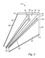
- a device 10 for mounting a strip 11 of light emitting diodes which also is known as an LED strip, according to one embodiment example is illustrated.
- the device 10 is illustrated without the strip 11 in Figs. 1 , 3 and 4 and with the strip 11 in Fig. 2 .
- the device 10 is arranged as a mounting strip for holding the LED strip 11.
- the device 10 can be elongated and can be arranged in any suitable length. For example, the device 10 can be cut into the desired length.
- the device 10 comprises a first portion 12 and a second portion 13 connected to the first portion 12.
- the first and second portions 12, 13 are elongated and are, for example, formed as strips.
- the second portion 13 is arranged substantially perpendicular to the first portion 12.
- the first portion 12 has a first end 14 and a second end 15, wherein the second portion 13 has a first end 16 and a second end 17.
- the first end 14 of the first portion 12 is connected to the first end 16 of the second portion 13 forming a substantially L-shaped cross section.
- the second end 15 of the first portion 12 and the second end 17 of the second portion 13 are free ends.
- the first and second portions 12, 13 are, for example, made of a rigid or flexible material, such as a suitable polymer material, rubber, metal or wood.
- the first and second portions 12, 13 are made of polycarbonate or a material having similar properties.
- the first portion 12 has a first side 18 and an opposite second side 19. Also the second portion has a first side 20 and an opposite second side 21.
- the first side 18 of the first portion 12 is arranged for engaging a surface, which is described more in detail below.
- the second side 19 of the first portion 12 is provided with a first projection 22, wherein the second side 21 of the second portion 13 is provided with a second projection 23.
- the first projection 22 projects substantially perpendicular from the first portion 12 and substantially in parallel with the second portion 13, wherein the second projection 23 projects substantially perpendicular from the second portion 13 and substantially in parallel with the first portion 12.
- the second projection 23 extends towards the first projection 22.
- the first projection 22 is arranged a distance from the first end 14 of the first portion 12, wherein the second projection 23 is arranged a distance from the first end 16 of the second portion 13, the first and second portions 12, 13 and the first and second projections 22, 23 forming a space 24 for receiving the strip 11.
- the first and second projections 22, 23 are arranged for engaging the strip 11 to retain the strip 11 in the space 24.
- the space 24 is arranged with a substantially rectangular cross section.
- the space 24 is arranged with another cross section shape, such as a polygonal or rounded shape.
- the first projection 22 is flexible, so that it can be displaced, for example rotated or bent away, in a direction away from the second portion 13 and the second projection 23 to facilitate insertion of the strip 11 into the space 24, which will be described in more detail below.
- the first projection 22 is resiliently flexible so as to return to its original position when a displacing force upon it ceases.
- the second projection 23 can be rigid or flexible, such as resiliently flexible.
- the first projection 22 is longer than the second projection 23.
- the first projection 22 comprises a resilient material or a resilient device.
- the first projection 22 is, for example, made of a resilient material or is connected to the first portion 12 by means of a resilient material or device.
- a resilient device is a conventional spring.
- first and second projections 22, 23 are continuous, i.e. uninterrupted, and extend along the length of the first and second portions 12, 13, respectively.
- first and second projections 22, 23 may engage the strip 11 along substantially the entire length of the strip 11 supported by the device 10.
- the first and second projections 22, 23 are interrupted, so that a plurality of projections 22, 23 is distributed along the first and second portions 12, 13, respectively, at suitable intervals.
- the first projection 22 is provided with a protrusion 25, so that the strip 11 is partially enclosed when arranged in the space 24.
- the protrusion 25 extends in a direction towards the second portion 13 and the second projection 23, so that the protrusion 25 and the second projection 23 engage the same side of the strip 11 when the strip 11 is arranged in the space 24.
- the protrusion 25 and the second projection 23 engage a visible or light emitting side of the strip 11 when the strip 11 is arranged in the space 24.
- the remaining sides of the strip 11 is hidden or at least partially hidden, by the first projection 22, the first portion 12 and the second portion 13.
- the protrusion 25 is formed by a portion of the first projection 22 angled towards the second portion 13.
- the protrusion 25 is formed by a U-turn or V-shaped portion of the first projection 22.
- the first projection 22 is terminated with the protrusion 25.
- the first projection 22 is made of or provided with a material having high friction against the strip 11, so as to retain the strip 11 in the space 24 instead of the protrusion 25 illustrated in the drawings.
- the protrusion 25 extends continuously, i.e. uninterrupted, along substantially the entire length of the first projection 12, wherein the strip 11 arranged in the space 24 is supported by the protrusion 25 substantially along its entire length. Support of the strip 11 along substantially its entire length can result in that the strip 11 is held more firmly in position in the space 24, which may prevent the strip from hanging down.
- the protrusion 25 is interrupted, so that a plurality of protrusions 25 is distributed along the first projection at a suitable interval.
- the first portion 12 optionally extends beyond the first projection 22, forming a first extended part 26 between the first projection 22 and the second end 15 of the first portion 12.
- the second portion 13 optionally extends beyond the second projection 23, forming a second extended part 27 between the second projection 23 and the second end 17 of the second portion 13.
- the first extended part 26 is arranged with a length or width substantially corresponding to the length or width of the second extended part 27.
- the device 10 holding the strip 11 is mounted in various positions to illustrate a few possible examples of mounting positions and applications.
- the strip 11 is arranged in the space 24 of the device 10, wherein the device 10 has been arranged on a surface 28 formed by a ceiling.
- the device 10 is arranged close to a wall 29 or similar, i.e. with a relatively small distance to the wall 29.
- the first side 18 of the first portion 12 is attached to the surface 28.
- the first portion 12 is arranged in parallel to the surface 28, wherein the second portion 13 projects substantially perpendicular from the surface 28.
- the first side 18 of the first portion 12 is provided with a fastener for attachment to the surface 28.
- the fastener is an adhesive, adhesive tape or similar for fastening the device 10 to the surface 28.
- the device 10 is fastened to the surface 28 by means of conventional mechanical fasteners, such as screws, nails, fittings, hooks, strings, hook and loop fasteners or any other suitable conventional fastener.
- the first extended part 26 of the first portion 12 can form an enlarged contact surface between the device 10 and the surface 28 on which the device 10 is to be mounted.
- the extended part 26 can form an area suitable for mechanical fasteners.
- the second extended part 27 of the second portion 13 can form a screen for screening off the strip 11, so that the strip 11 is less visible.
- the second extended part 27 is arranged so that the light emitting side of the strip 11 not easily is directly visible.
- the second side 21 of the second portion 13 can comprise a light reflecting surface.
- the device 10 is mounted on a surface 28 under a shelf or similar.
- the device 10 is holding a strip 11 of light emitting diodes.
- the device 10 can be mounted in a similar manner on a surface 28 under a wall cupboard or any other suitable surface 28.
- the device 10 is arranged in an area close to a free end of the surface 28 and a distance from the wall 27, wherein the first portion 12 is arranged in contact with the surface 28 and the second extended part 27 of the second portion 13 extends from the surface 28 to form a screen screening off the strip 11, so that the strip 11 is less visible or not easily directly visible.
- the first portion 12 is provided with a fastener for connecting the device 10 to the surface 28.
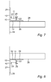
- a strip 11 arranged in a device 10 is illustrated, wherein the device 10 is mounted on a surface 28 on the top of a shelf or similar.
- the first portion 12 is arranged in contact with the surface 28, wherein the second portion 13 is engaging the wall 29 or similar.
- the second extended part 27 of the second portion 13 is not used as a screen.
- the second part 13 is fastened to the wall 29.
- the second part 13 can optionally be provided with fasteners, adhesive, adhesive tape or similar in a corresponding manner as the first portion 12.
- the first portion 12 and/or the second portion 13 can be provided with the fastener for connecting the device 10 to the surface 28.
- the device 10 carrying the strip 11 is arranged on a surface 28 under a shelf or similar.
- the first portion 12 is arranged in contact with the surface 28, wherein the second portion 13 is arranged in contact with the wall 29.
- the first portion 12 and/or the second portion 13 is provided with the fastener for connecting the device 10 to the surface 28.
- the second portion 13 is provided with a notch 30, so that the second portion 13 is breakable along the notch 30.
- the notch 30 is arranged between the second projection 23 and the free second end 17 of the second portion 13.
- the notch 30 is provided to facilitate removal of substantially the second extended part 27 of the second portion 13 if desired.
- the notch 30 can be provided close to or adjacent the second projection 23.
- the protrusion 25 on the first projection 22 is arranged as a rounded part extending from the first projection 22.
- the protrusion 25 in the form of the rounded part extends towards the second portion 13 and the second projection 23.
- the rounded part extends perpendicular or substantially perpendicular from the first projection 22.
- the protrusion 25 is arranged at the free end of the first projection 22, wherein the first projection 22 is terminated with the protrusion 25.
- the protrusion 25 is provided with edges or is bevelled.
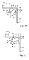
- Figs. 11 and 12 one example of the mounting of the strip 11 in the device 10 is illustrated.
- the device 10 is in a default or resting position, wherein no force is applied to the first projection 12 or the protrusion 22.
- a portion of the strip 11 is inserted between the first and second projections 22, 23 and into the space 24, wherein the strip 11 is inclined in relation to the space 24.
- a light emitting side 31, i.e. a main light emitting side, front side or visible side, of the strip 11 is brought into contact with the second projection 23. Then, the strip 11 is pushed towards the flexible first projection 22 or the protrusion 25 in a direction illustrated by means of arrow A in Fig.
- the first projection 22 is displaced in a direction illustrated by means of arrow B.
- the first projection 22 is displaced away from the second projection 23 so as to enlarge the distance between the protrusion 25 and the second projection 23 to facilitate insertion of the strip 11 into the space 24.
- the free end of the first projection 22 is displaced towards the second end 15 of the first portion 12.
- the first projection 22 is bent or rotated away from the second projection 23.
- the strip 11 engages at least the protrusion 25 and the second projection 23.
- the light emitting side 31 of the strip 11 engages the protrusion 25 and the second projection 23.
- the opposite side 32 of the strip 11, i.e. the side opposite the light emitting side 31, is facing the first portion 12.
- the first projection 22 can be displaced by the fingers of a person, while the strip 11 is fitted into the space. It is also to be understood that the strip 11 can be arranged in the space in other ways. For example, in an embodiment example in which the second projection 23 is flexible, the second projection 23 can be displaced in addition to or instead of the first projection 22. It is also to be understood that the strip 11 initially can be brought into contact with the first projection 22 and then into contact with the second projection 23.
Priority Applications (2)
| Application Number | Priority Date | Filing Date | Title |
|---|---|---|---|
| EP20100194540 EP2463573A1 (fr) | 2010-12-10 | 2010-12-10 | Dispositif et procédé d'assemblage d'une bande de diodes électroluminescentes |
| US13/312,035 US20120147610A1 (en) | 2010-12-10 | 2011-12-06 | Device for mounting a strip of light emitting diodes |
Applications Claiming Priority (1)
| Application Number | Priority Date | Filing Date | Title |
|---|---|---|---|
| EP20100194540 EP2463573A1 (fr) | 2010-12-10 | 2010-12-10 | Dispositif et procédé d'assemblage d'une bande de diodes électroluminescentes |
Publications (1)
| Publication Number | Publication Date |
|---|---|
| EP2463573A1 true EP2463573A1 (fr) | 2012-06-13 |
Family
ID=43941470
Family Applications (1)
| Application Number | Title | Priority Date | Filing Date |
|---|---|---|---|
| EP20100194540 Withdrawn EP2463573A1 (fr) | 2010-12-10 | 2010-12-10 | Dispositif et procédé d'assemblage d'une bande de diodes électroluminescentes |
Country Status (2)
| Country | Link |
|---|---|
| US (1) | US20120147610A1 (fr) |
| EP (1) | EP2463573A1 (fr) |
Cited By (1)
| Publication number | Priority date | Publication date | Assignee | Title |
|---|---|---|---|---|
| EP3577392A4 (fr) * | 2017-01-31 | 2020-11-18 | Scott David Moore | Dispositif de montage et système de conditionnement de produit d'éclairage |
Families Citing this family (3)
| Publication number | Priority date | Publication date | Assignee | Title |
|---|---|---|---|---|
| US11058961B2 (en) * | 2017-03-09 | 2021-07-13 | Kaleb Matson | Immersive device |
| US10625170B2 (en) * | 2017-03-09 | 2020-04-21 | Lumena Inc. | Immersive device |
| EP3862620A1 (fr) * | 2020-02-04 | 2021-08-11 | Lumileds LLC | Intégration mécanique de bandes de del flexibles |
Citations (3)
| Publication number | Priority date | Publication date | Assignee | Title |
|---|---|---|---|---|
| US5222799A (en) * | 1990-08-21 | 1993-06-29 | Diamond Stairlight Industries | Stair lights |
| DE202004001198U1 (de) * | 2004-01-28 | 2005-06-09 | Halemeier Gmbh & Co. Kg | Nischenleuchte |
| EP2012054A2 (fr) * | 2007-06-21 | 2009-01-07 | Alliance Optotek Co.,Ltd. | Ensemble de fixation et connexion de lampe barre |
Family Cites Families (3)
| Publication number | Priority date | Publication date | Assignee | Title |
|---|---|---|---|---|
| US7632004B2 (en) * | 2004-07-06 | 2009-12-15 | Tseng-Lu Chien | LED night light with more than 1 optics means |
| GB2442013A (en) * | 2006-09-21 | 2008-03-26 | Hogarth Fine Art Ltd | A lamp with repositionable LEDs |
| EP2153120B1 (fr) * | 2007-05-02 | 2022-03-23 | Luminator Holding, L.P. | Procédé et système d'éclairage |
-
2010
- 2010-12-10 EP EP20100194540 patent/EP2463573A1/fr not_active Withdrawn
-
2011
- 2011-12-06 US US13/312,035 patent/US20120147610A1/en not_active Abandoned
Patent Citations (3)
| Publication number | Priority date | Publication date | Assignee | Title |
|---|---|---|---|---|
| US5222799A (en) * | 1990-08-21 | 1993-06-29 | Diamond Stairlight Industries | Stair lights |
| DE202004001198U1 (de) * | 2004-01-28 | 2005-06-09 | Halemeier Gmbh & Co. Kg | Nischenleuchte |
| EP2012054A2 (fr) * | 2007-06-21 | 2009-01-07 | Alliance Optotek Co.,Ltd. | Ensemble de fixation et connexion de lampe barre |
Cited By (1)
| Publication number | Priority date | Publication date | Assignee | Title |
|---|---|---|---|---|
| EP3577392A4 (fr) * | 2017-01-31 | 2020-11-18 | Scott David Moore | Dispositif de montage et système de conditionnement de produit d'éclairage |
Also Published As
| Publication number | Publication date |
|---|---|
| US20120147610A1 (en) | 2012-06-14 |
Similar Documents
| Publication | Publication Date | Title |
|---|---|---|
| RU2504625C2 (ru) | Потолок со скрытой подвесной системой со снимаемыми вниз панелями | |
| US6651945B2 (en) | Device for hanging articles | |
| EP2463573A1 (fr) | Dispositif et procédé d'assemblage d'une bande de diodes électroluminescentes | |
| US20100230551A1 (en) | Device and method for suspending and retaining telecommunication and power cables within a building | |
| US20180031212A1 (en) | Hidden mounting system for luminaire | |
| KR101508883B1 (ko) | 천정등 결착장치 | |
| AU2014212746B2 (en) | Clip for perimeter trim | |
| US10975593B2 (en) | Railing system | |
| US20110110106A1 (en) | Light fixture for mounting to a ceiling | |
| US20150109804A1 (en) | Apparatuses and methods for installing light modules | |
| US20230095202A1 (en) | Enclosed gutter clip and expandable bulb-holding clip | |
| MX2008007443A (es) | Soporte de etiqueta para ganchos de exhibicion de mercancia y metodo para hacer el mismo. | |
| US9603468B2 (en) | Holding device for a bracket in a storage system | |
| EP2650989B1 (fr) | Suspente assistée d'un organe de fixation | |
| RU2500321C2 (ru) | Устройство и система крепления принадлежностей для полок | |
| JP6877351B2 (ja) | キャンバス取付デバイス | |
| RU136929U1 (ru) | Поддерживающий крюк для кабеля | |
| JP6585160B2 (ja) | 固定デバイス | |
| JP2012235738A (ja) | 害虫捕獲トラップ | |
| KR102044170B1 (ko) | 조명 장치 | |
| CA2820345C (fr) | Presentoir de type tablette | |
| US9157616B2 (en) | Candle holder mount | |
| US20130277525A1 (en) | Rail, adhesive mounted, to display utensils and other objects. | |
| US20220225811A1 (en) | Panel hook | |
| WO2016090456A1 (fr) | Porte-accessoire pour système de garde-corps |
Legal Events
| Date | Code | Title | Description |
|---|---|---|---|
| PUAI | Public reference made under article 153(3) epc to a published international application that has entered the european phase |
Free format text: ORIGINAL CODE: 0009012 |
|
| AK | Designated contracting states |
Kind code of ref document: A1 Designated state(s): AL AT BE BG CH CY CZ DE DK EE ES FI FR GB GR HR HU IE IS IT LI LT LU LV MC MK MT NL NO PL PT RO RS SE SI SK SM TR |
|
| AX | Request for extension of the european patent |
Extension state: BA ME |
|
| STAA | Information on the status of an ep patent application or granted ep patent |
Free format text: STATUS: THE APPLICATION IS DEEMED TO BE WITHDRAWN |
|
| 18D | Application deemed to be withdrawn |
Effective date: 20121214 |