EP2463498A1 - Crankshaft of internal combustion engine provided with multi link-type piston-crank mechanism and multi link-type piston-crank mechanism of internal combustion engine - Google Patents
Crankshaft of internal combustion engine provided with multi link-type piston-crank mechanism and multi link-type piston-crank mechanism of internal combustion engine Download PDFInfo
- Publication number
- EP2463498A1 EP2463498A1 EP10799684A EP10799684A EP2463498A1 EP 2463498 A1 EP2463498 A1 EP 2463498A1 EP 10799684 A EP10799684 A EP 10799684A EP 10799684 A EP10799684 A EP 10799684A EP 2463498 A1 EP2463498 A1 EP 2463498A1
- Authority
- EP
- European Patent Office
- Prior art keywords
- crankpin
- pin
- link
- crankshaft
- piston
- Prior art date
- Legal status (The legal status is an assumption and is not a legal conclusion. Google has not performed a legal analysis and makes no representation as to the accuracy of the status listed.)
- Granted
Links
Images




Classifications
-
- F—MECHANICAL ENGINEERING; LIGHTING; HEATING; WEAPONS; BLASTING
- F16—ENGINEERING ELEMENTS AND UNITS; GENERAL MEASURES FOR PRODUCING AND MAINTAINING EFFECTIVE FUNCTIONING OF MACHINES OR INSTALLATIONS; THERMAL INSULATION IN GENERAL
- F16C—SHAFTS; FLEXIBLE SHAFTS; ELEMENTS OR CRANKSHAFT MECHANISMS; ROTARY BODIES OTHER THAN GEARING ELEMENTS; BEARINGS
- F16C3/00—Shafts; Axles; Cranks; Eccentrics
- F16C3/04—Crankshafts, eccentric-shafts; Cranks, eccentrics
- F16C3/06—Crankshafts
- F16C3/14—Features relating to lubrication
-
- F—MECHANICAL ENGINEERING; LIGHTING; HEATING; WEAPONS; BLASTING
- F02—COMBUSTION ENGINES; HOT-GAS OR COMBUSTION-PRODUCT ENGINE PLANTS
- F02B—INTERNAL-COMBUSTION PISTON ENGINES; COMBUSTION ENGINES IN GENERAL
- F02B75/00—Other engines
- F02B75/04—Engines with variable distances between pistons at top dead-centre positions and cylinder heads
- F02B75/045—Engines with variable distances between pistons at top dead-centre positions and cylinder heads by means of a variable connecting rod length
-
- F—MECHANICAL ENGINEERING; LIGHTING; HEATING; WEAPONS; BLASTING
- F02—COMBUSTION ENGINES; HOT-GAS OR COMBUSTION-PRODUCT ENGINE PLANTS
- F02B—INTERNAL-COMBUSTION PISTON ENGINES; COMBUSTION ENGINES IN GENERAL
- F02B75/00—Other engines
- F02B75/04—Engines with variable distances between pistons at top dead-centre positions and cylinder heads
- F02B75/048—Engines with variable distances between pistons at top dead-centre positions and cylinder heads by means of a variable crank stroke length
-
- F—MECHANICAL ENGINEERING; LIGHTING; HEATING; WEAPONS; BLASTING
- F02—COMBUSTION ENGINES; HOT-GAS OR COMBUSTION-PRODUCT ENGINE PLANTS
- F02F—CYLINDERS, PISTONS OR CASINGS, FOR COMBUSTION ENGINES; ARRANGEMENTS OF SEALINGS IN COMBUSTION ENGINES
- F02F7/00—Casings, e.g. crankcases
- F02F7/0002—Cylinder arrangements
- F02F7/0019—Cylinders and crankshaft not in one plane (deaxation)
-
- F—MECHANICAL ENGINEERING; LIGHTING; HEATING; WEAPONS; BLASTING
- F16—ENGINEERING ELEMENTS AND UNITS; GENERAL MEASURES FOR PRODUCING AND MAINTAINING EFFECTIVE FUNCTIONING OF MACHINES OR INSTALLATIONS; THERMAL INSULATION IN GENERAL
- F16C—SHAFTS; FLEXIBLE SHAFTS; ELEMENTS OR CRANKSHAFT MECHANISMS; ROTARY BODIES OTHER THAN GEARING ELEMENTS; BEARINGS
- F16C33/00—Parts of bearings; Special methods for making bearings or parts thereof
- F16C33/02—Parts of sliding-contact bearings
- F16C33/04—Brasses; Bushes; Linings
- F16C33/06—Sliding surface mainly made of metal
- F16C33/10—Construction relative to lubrication
- F16C33/1025—Construction relative to lubrication with liquid, e.g. oil, as lubricant
- F16C33/1045—Details of supply of the liquid to the bearing
- F16C33/1055—Details of supply of the liquid to the bearing from radial inside, e.g. via a passage through the shaft and/or inner sleeve
-
- F—MECHANICAL ENGINEERING; LIGHTING; HEATING; WEAPONS; BLASTING
- F16—ENGINEERING ELEMENTS AND UNITS; GENERAL MEASURES FOR PRODUCING AND MAINTAINING EFFECTIVE FUNCTIONING OF MACHINES OR INSTALLATIONS; THERMAL INSULATION IN GENERAL
- F16C—SHAFTS; FLEXIBLE SHAFTS; ELEMENTS OR CRANKSHAFT MECHANISMS; ROTARY BODIES OTHER THAN GEARING ELEMENTS; BEARINGS
- F16C9/00—Bearings for crankshafts or connecting-rods; Attachment of connecting-rods
- F16C9/04—Connecting-rod bearings; Attachments thereof
-
- Y—GENERAL TAGGING OF NEW TECHNOLOGICAL DEVELOPMENTS; GENERAL TAGGING OF CROSS-SECTIONAL TECHNOLOGIES SPANNING OVER SEVERAL SECTIONS OF THE IPC; TECHNICAL SUBJECTS COVERED BY FORMER USPC CROSS-REFERENCE ART COLLECTIONS [XRACs] AND DIGESTS
- Y10—TECHNICAL SUBJECTS COVERED BY FORMER USPC
- Y10T—TECHNICAL SUBJECTS COVERED BY FORMER US CLASSIFICATION
- Y10T74/00—Machine element or mechanism
- Y10T74/21—Elements
- Y10T74/2173—Cranks and wrist pins
- Y10T74/2181—Variable
-
- Y—GENERAL TAGGING OF NEW TECHNOLOGICAL DEVELOPMENTS; GENERAL TAGGING OF CROSS-SECTIONAL TECHNOLOGIES SPANNING OVER SEVERAL SECTIONS OF THE IPC; TECHNICAL SUBJECTS COVERED BY FORMER USPC CROSS-REFERENCE ART COLLECTIONS [XRACs] AND DIGESTS
- Y10—TECHNICAL SUBJECTS COVERED BY FORMER USPC
- Y10T—TECHNICAL SUBJECTS COVERED BY FORMER US CLASSIFICATION
- Y10T74/00—Machine element or mechanism
- Y10T74/21—Elements
- Y10T74/2173—Cranks and wrist pins
- Y10T74/2185—Lubricated
Definitions
- the present invention relates to a crankshaft of an internal combustion engine provided with a multi-link piston-crank mechanism.
- multi-link mechanism a multi-link piston-crank mechanism
- a piston pin of a piston and a crankpin of a crankshaft are linked to each other via a plurality of links, as a primary kinetic system in which the piston and the crankshaft of an internal combustion engine are linked to each other.
- a crankthrow corresponding to a distance from the axis of a crankshaft main journal to the axis (a rotation center) of a crankpin, is one-half (1/2) of the piston stroke, except a specific case that the axis of the main journal is offset from the cylinder centerline.
- the main journal and the crankpin can be laid out so as to approach each other in a decentering direction of the crankpin, and hence, as viewed in the axial direction of the crankshaft, the overlapping area, in which the main journal and the crankpin are overlapped with each other, tends to become greater, thus ensuring the enhanced rigidity and strength of the crankshaft.
- the crankshaft is formed with oil passages for lubricating bearing portions of crankpins.
- lubricating oil is supplied from the cylinder-block side to the oil passage.
- One end of the oil passage, that is, the oil-passage pin-side opening is configured to be open at the outer peripheral surface of the crankpin. Note that a large magnitude of combustion load acts on the crankshaft in a decentering direction of the crankpin whose axis is displaced from the axis of the main journal.
- the oil-passage pin-side opening is generally formed at an angular position of 90° or -90° with respect to a reference line extending in the crankpin decentering direction, that is, on either side of diametrically-opposing positions of both sides of the crankpin in the crankpin transverse direction perpendicular to the crankpin decentering direction.
- a crankthrow is set shorter than one-half of a (maximum) piston stroke
- a torsional moment (hereinafter referred to as "torsional torque T"), acting about the crank axis, is caused by resonance.
- a load P in the crankpin transverse direction perpendicular to both the crank axial direction Z and the crankpin decentering direction X.
- a bending moment acting about the crank axis is produced.
- the oil-passage pin-side opening configured to be open at the outer peripheral surface of the crankpin, is formed at a position of 90° or -90° (i.e., 270° crankangle in the crank rotation direction) with respect to a reference line extending in the crankpin decentering direction.
- a stress concentration occurs in the vicinity of the oil-passage pin-side opening.
- the present invention has been realized, while paying its attention to a demerit newly caused by a crankthrow shortened by using a multi-link mechanism. That is, the present invention relates to a crankshaft of an internal combustion engine employing a multi-link piston-crank mechanism having an upper link whose one end is linked to a piston via a piston pin, a lower link linked to the other end of the upper link via an upper pin and also linked to a crankpin of a crankshaft, and an auxiliary link, one end of the auxiliary link being pivotally supported on a main-body side of the engine, and the other end of the auxiliary link being linked to the lower link via an auxiliary pin.
- a multi-link piston-crank mechanism having an upper link whose one end is linked to a piston via a piston pin, a lower link linked to the other end of the upper link via an upper pin and also linked to a crankpin of a crankshaft, and an auxiliary link, one end of the auxiliary link being pivotally supported on a main-
- a crankthrow from the axis of a main journal of the crankshaft to the axis of the crankpin is set shorter than one-half of a stroke of the piston. Additionally, as viewed in the crank axial direction, the crankpin and the main journal are overlapped with each other.
- the pin-side opening is formed in ranges other than angular ranges of 90° or -90° with respect to the reference line extending from the axis of the main journal toward the axis of the crankpin in the crankpin decentering direction, that is, formed in ranges other than both sides of the crankpin in its transverse direction.
- a pin-side opening of an oil passage configured to be open at an outer peripheral surface of a crankpin, is formed in ranges other than both sides of the crankpin in the crankpin transverse direction, thereby suppressing or alleviating a stress concentration occurring in the vicinity of the pin-side opening owing to torsional torque, and consequently achieving the compactified crankpin whose diameter is properly reduced, while ensuring a required strength and rigidity.
- FIGs. 13-14 are assembled/disassembled views schematically illustrating a multi-link piston-crank mechanism (simply, a multi-link mechanism) of an internal combustion engine to which a crankshaft of the invention is applied.
- a cylinder block 14 has a plurality of cylinders formed therein.
- a piston 8 is slidably fitted in each of the cylinders.
- a main journal 2 of a crankshaft 1 is rotatably supported on the cylinder block.
- the multi-link mechanism is comprised of an upper link 6 whose one end is linked to the piston 8 via a piston pin 7, a lower link 4 linked to the other end of the upper link 5 via an upper pin 6 and also linked to a crankpin 3 of the crankshaft 1, and an auxiliary link 10, one end (the lower end) of the auxiliary link being pivotally supported on the side of cylinder block 14, corresponding to a main-body side of the internal combustion engine, and the other end (the upper end) of the auxiliary link being linked to the lower link 4 via an auxiliary pin 11.
- crankshaft 1 main journal 2 and crankpin 3 are connected via a crank web 14.
- L1 denotes a crankthrow from the axis of main journal 2 to the axis of crankpin 3
- L2 denotes a distance from the geometric center of the crankpin bearing portion of lower link 4 to the geometric center of the upper-pin bearing portion of lower link 4
- L3 denotes a distance from the geometric center of the auxiliary-pin bearing portion of auxiliary link 10 to the geometric center of an eccentric shaft portion 12B
- L4 denotes a distance from the geometric center of the crankpin bearing portion of lower link 4 to the geometric center of the auxiliary-pin bearing portion of lower link 4
- L6 denotes a distance from the geometric center of the piston-pin bearing portion of upper link 5 to the geometric center of the upper-pin bearing portion of upper link 5
- x4 denotes an offset amount of the center of piston pin 7 (reciprocating along a cylinder centerline) from the crankshaft main journal centerline.
- crankthrow L1 is set shorter than one-half of the (maximum) piston stroke.
- a crankthrow is one-half of a piston stroke
- the shortened crankthrow L1 it is possible to attain the enhanced rigidity and strength and downsizing.
- high-compression-ratio engine for the same length of crankthrow L1, it is possible to attain high-compression-ratio engine.
- the crankshaft has such an overlapping area (denoted by ⁇ OL in Fig. 1B ), in which the crankpin and the main journal are overlapped with each other in the decentering direction of the crankpin.
- auxiliary shaft 12 which extends continuously over the plurality of cylinders, is rotatably supported on the cylinder block 14 via support members (not shown).
- Auxiliary shaft 12 has the previously-discussed auxiliary shaft portion 12B provided for each engine cylinder.
- the other end of auxiliary link 10 is pivotably linked to the associated eccentric shaft portion 12B.
- auxiliary shaft 12 by changing the rotational position of auxiliary shaft 12 by means of an actuator (not shown) depending on engine operating conditions, the position of eccentric shaft portion 12B, serving as a fulcrum of oscillating motion of auxiliary link 10, can be changed, and therefore an engine compression ratio can be changed owing to a change in a motion-restriction condition that motion of lower link 4 is restricted by means of auxiliary link 10 (variable compression ratio means).
- auxiliary link 10 variable compression ratio means
- crankshaft 1 has an oil passage 20 formed therein, for supplying lubricating oil from the cylinder-block side to the crankpin bearing portion.
- One end of oil passage 20, that is, a pin-side opening 21 is configured to be open at the outer peripheral surface of crankpin 3.
- the oil-passage pin-side opening configured to be open at the outer peripheral surface of the crankpin, is located and formed in either one of angular ranges P1-P4, substantially corresponding to 45 degrees, 135 degrees, 225 degrees, and 315 degrees in a crank rotation direction ⁇ (i.e., in a revolving direction of crankpin 3 about the main journal 2) with respect to a reference line X1 extending from the main journal toward the axis of the crankpin in the crankpin decentering direction X.
- the center position of pin-side opening 21 is formed in either one of angular positions of 45 degrees, 135 degrees, 225 degrees, and 315 degrees, or formed in either one of angular ranges of 45° ⁇ 10°, 135° ⁇ 10°, 225° ⁇ 10°, and 315° ⁇ 10°.
- pin-side opening 21 is formed in ranges other than angular ranges Q1 and Q3 in which combustion load and/or inertial load acts in the crankpin decentering direction X, that is, angular ranges Q1 and Q3, substantially corresponding to 0° and 180° in the crank rotation direction ⁇ with respect to the reference line X1, or formed in ranges other than angular ranges Q2 and Q4 in which a load caused by torsional torque acts in the crankpin transverse direction Y, that is, angular ranges Q2 and Q4, substantially corresponding to 90° and 270° (-90°) in the crank rotation direction ⁇ with respect to the reference line X1.
- the pin-side opening is formed in angular ranges Q2 and Q4 in the crankpin transverse direction Y, that is, in angular ranges Q2 and Q4, corresponding to diametrically-opposing portions of both sides of the crankpin in the crankpin transverse direction.
- a stress concentration tends to occur in the vicinity of the pin-side opening owing to a load caused by torsional torque and acting in the crankpin transverse direction Y. Also, this leads to the difficulty of ensuring an oil film in the vicinity of the pin-side opening.
- pin-side opening 21 in ranges other than angular ranges Q2 and Q4, corresponding to diametrically-opposing portions of both sides of the crankpin in the crankpin transverse direction, such a stress concentration can be suppressed and alleviated, thereby reducing the diameter of the crankpin, while ensuring a required strength and rigidity, and consequently achieving compactification. Additionally, it is possible to suppress a lack of oil film in the vicinity of the pin-side opening 21, thus enabling a good fluid-lubricating action.
- Fig. 17 shows a change in stress (a combined stress of a bending stress and a shearing stress) produced in the oil passage owing to torsion of the crankshaft in accordance with a change in the position of formation of the oil-passage pin-side opening in the internal combustion engine to which the multi-link piston-crank mechanism (the multi-link mechanism) shown in Fig. 13 is applied.
- the internal combustion engine is an in-line four-cylinder internal combustion engine of 1.6-L displacement, provided with a multi-link piston-crank mechanism and a crankshaft 1, which includes crankpins 3, each having a diameter of 35 millimeters and made of chromium molybdenum steel material, such as SCM440H.
- a distance (a leverage) from the center of the connecting pin of control link 10 and lower link 4 to the center of the connecting pin of upper link 5 and lower link 4 is set to 1.9.
- crankpin 3 is overlapped with the main journal 2 of crankshaft 1 by 22.8 millimeters in the crankpin decentering direction.
- the stress (the combined stress of bending stress and shearing stress), produced in the oil passage owing to torsion (torsional oscillation), tends to exceed a fatigue limit (a critical stress), set based on a stress amplitude and a mean stress.
- the angular ranges Q2 and Q4 in the crankpin transverse direction Y, in which the oil-passage pin-side opening 21 should not be formed substantially correspond to an angular range from 60 degrees to 120 degrees and an angular range from 240 degrees to 300 degrees.
- angle basically means an angle measured in the crank rotation direction ⁇ with respect to the reference line X1 extending from the crankpin center taken as an origin.
- oil passage 20 is formed to straightly penetrate the inside of crankpin 3, crank web 14, and main journal 2 over the entire length from the pin-side opening 21, which is open at the outer peripheral surface of crankpin 3 to a journal-side opening 22, which is open at the outer peripheral surface of main journal 2.
- the previously-noted oil passage 20 is formed in the overlapping range ⁇ OL in which crankpin 3 and main journal 2 are overlapped with each other in the crankpin decentering direction X.
- the pin-side opening 21 is located and formed in either one of angular ranges, substantially corresponding to 135 degrees and 225 degrees in the crank rotation direction with respect to the reference line X1
- the journal-side opening 22 is located and formed in either one of angular ranges, substantially corresponding to 315 degrees and 45 degrees in the crank rotation direction with respect to the reference line X1. That is, oil passage 20 is arranged within the overlapping range ⁇ OL and formed in ranges other than angular ranges Q1-Q4 (see Fig. 15 ), in which a large magnitude of load acts, in a manner so as to obliquely penetrate straight, as viewed in the crank axial direction.
- each of the openings are exaggeratedly shown such that the inside diameter of each of openings 21-22 is greater than that of oil passage 20, but actually, oil passage 20 is formed as a through hole having the same cross-section as each of the openings 21-22.
- the overlapping area ⁇ OL increases and thus the strength and rigidity thereof also increase.
- the oil passage 20 by way of which the outer peripheries of main journal 2 and crankpin 3 are connected each other straightly and directly.
- machining the straight oil passage 20 eliminates the need for forming additional radial oil passages in the crankpin and/or the main journal. This contributes to the reduced machining time and costs, and also ensures a required strength and rigidity.
- a radial oil passage 24 is further formed to penetrate crankpin 3 in the diametral direction of the crankpin.
- Radial oil passage 24 has two opposite openings, which are open at the outer peripheral surface of crankpin 3, namely, the first pin-side opening 24A located and formed in an angular range substantially corresponding to 135 degrees, and the second pin-side opening 24B located and formed in an angular range substantially corresponding to 315 degrees.
- Lubricating oil is supplied from the cylinder-block side via another oil passage (not shown) formed in the crankshaft to the radial oil passage 24, and then further delivered through the pin-side openings 24A-24B to the crankpin bearing portion.
- radial oil passage 24 is formed to straightly penetrate crankpin 3 in the diametral direction of the crankpin, thus facilitating machining. Additionally, oil can be supplied to the crankpin bearing portion through the two opposite pin-side openings 24A-24B of both ends of radial oil passage 24, thus resulting in an increase in the lubricating-oil amount.
- a radial oil passage 25 is further formed to penetrate crankpin 3 in the diametral direction of the crankpin.
- Lubricating oil is supplied from the cylinder-block side via another oil passage (not shown) formed in the crankshaft to the radial oil passage 25, and then further delivered through pin-side openings 25A-25B to the crankpin bearing portion.
- the third embodiment differs from the second embodiment, in that the first pin-side opening 25A of radial oil passage 25, which is open at the outer peripheral surface of crankpin 3, is located and formed in an angular range substantially corresponding to 45 degrees around the crankpin, and the second pin-side opening 25B, which is open at the outer peripheral surface of crankpin 3, is located and formed in an angular range substantially corresponding to 225 degrees around the crankpin.
- crankangle corresponding to the piston TDC position
- crankangle at which the crankpin decentering direction X is identical to the crankshaft main journal centerline
- combustion load acting from the crankpin side toward the main journal side tends to act in an angular range substantially corresponding to an angle displaced from the reference position of revolution of the crankshaft in the direction (i.e., in the clockwise direction) opposite to the crank rotation direction, that is, in an angular range substantially corresponding to 315 degrees (-45 degrees).
- the third embodiment is superior for the reasons discussed below. That is, in the third embodiment, radial oil passage 25 is formed to be obliquely inclined by 45 degrees in the crank rotation direction with respect to the crankpin decentering direction X, such that the pin-side openings 25A-25B are formed in the respective angular ranges, substantially corresponding to 45 degrees and 225 degrees. Thus, it is possible to suppress or alleviate the openings from being affected by combustion load acting in the angular range substantially corresponding to 315 degrees (-45 degrees).
- the crankpin has two radial oil passages 24-25, each formed to penetrate crankpin 3 in the diametral direction of the crankpin.
- the two opposite pin-side openings 24A-24B of the first radial oil passage 24, which are open at the outer peripheral surface of crankpin 3 are located and formed in respective angular ranges substantially corresponding to 135 degrees and 315 degrees.
- the two opposite pin-side openings 25A-25B of the second radial oil passage 25, which are open at the outer peripheral surface of crankpin 3, are located and formed in respective angular ranges substantially corresponding to 45 degrees and 225 degrees.
- four pin-side openings 24A, 24B, 25A, and 25B are formed in the outer peripheral surface of crankpin 3, thereby enabling a further increase in the amount of lubricating oil supplied to the crankpin bearing portion.
- crankshaft-side oil-passage structure of the lower-link side of the fifth embodiment, utilizing the crankshaft-side oil-passage structure well.
- four pin-side openings 24A, 24B, 25A, and 25B are formed in the outer peripheral surface of crankpin 3 in a manner so as to be circumferentially equidistant-spaced from each other, that is, in a manner so as to be open every predetermined angular intervals, such as 90 degrees.
- lower link 4 has a peripheral oil groove 27 and a splash hole 28 formed therein.
- Peripheral oil groove 27 is formed as a radially-outward recessed groove in the crankpin bearing surface of lower link 4 in a manner so as to extend in the peripheral direction over an angular range of 90 degrees.
- Splash hole 28 is provided to inject and supply lubricating oil toward a designated bearing portion, that is, the bearing portion of upper pin 6 in the fifth embodiment.
- One opening end of splash hole 28 is configured to open into the bottom face of peripheral oil groove 27, whereas the other opening end of splash hole 28 is configured to open into the bottom face of the forked pin-boss portion that supports the upper pin 6.
- lubricating oil, supplied from peripheral oil groove 27 to splash hole 28 can be injected and fed toward the upper-pin side (upper pin 6).
- pin-side openings 24A, 24B, 25A, and 25B are formed in the outer peripheral surface of crankpin 3 in a manner so as to be circumferentially equidistant-spaced from each other every predetermined angular intervals, such as 90 degrees.
- Peripheral oil groove 27 is circumferentially recessed in the lower-link side (lower link 4) over the same angular range (i.e., 90 degrees) as the angular interval between the two adjacent openings of these pin-side openings 24A, 24B, 25A, and 25B.
- either one of pin-side openings 24A, 24B, 25A, and 25B approaches the peripheral oil groove 27 in a manner so as to be brought into fluid-communication with the peripheral oil groove 27.
- the pin-side opening 24B is brought into fluid-communication with the peripheral oil groove 27.
- the pin-side opening 25B is brought into fluid-communication with the peripheral oil groove 27.
- lubricating oil can be supplied from either one of pin-side openings 24A, 24B, 25A, and 25B via peripheral oil groove 27 and then injected and delivered through splash hole 28 into the upper-pin side.
- a radially-penetrating upper-link side oil passage 29 may be formed in the pin-bearing portion of upper link 5 for upper pin 6, in a manner so as to be oriented substantially in the oil-splay direction of splash hole 28, and hence part of lubricating oil splayed from splash hole 28 can be more certainly supplied through the upper-link side oil passage 29 to the upper-pin bearing portion (upper pin 6).
- FIG. 8 there is shown the load diagram for the crankpin bearing portion.
- load acting on the crankpin bearing portion of lower link 4
- load tends to become high locally at predetermined angular ranges R1, R2, and R3. Therefore, in the sixth embodiment of Fig. 9 , peripheral oil groove 27 is formed in ranges of the crankpin bearing portion other than the above-mentioned angular ranges R1, R2, and R3, in which a large magnitude of load acts.
- peripheral oil groove 27 is formed in a 90° angular range whose center is an angular position intersecting with the direction X directed from the axis of the crankpin bearing portion of the lower link toward the axis of the upper-pin bearing portion (upper pin 6) of the lower link.
- three great loads namely, combustion load, inertial load at the piston TDC position, and inertial load at the piston BDC position from acting directly on the peripheral oil groove 27.
- an oil-sump portion 30 is formed in the crankpin bearing surface of lower link 4 as a recessed portion extending in the axial direction of the crankpin.
- Oil-sump portion 30 is connected to the upstream-side end of peripheral oil groove 27 in the direction of sliding motion of the bearing portion (i.e., in the rotation direction of the crankpin bearing portion of lower link 4). Additionally, the oil-sump portion is formed to extend to the vicinity of each axial end of the crankpin bearing portion of lower link 4. However, oil-sump portion 30 is closed at both ends without extending to each axial end of the crankpin bearing portion of lower link 4.
- lubricating oil supplied from the crankpin-side (crankpin 3) oil passage to peripheral oil groove 27 of lower link 4, can be delivered into the oil-sump portion 30 by virtue of rotation of crankpin 3. Additionally, due to a shearing stress arising from viscosity, part of lubricating oil is flown out in such a manner as to be dragged in the direction of sliding motion of the crankpin (i.e., in the rotation direction of crankpin 3 relative to the crankpin bearing portion of lower link 4), that is, in the direction opposite to the direction of sliding motion of the crankpin bearing portion, thus ensuring stable supply of lubricating oil to the crankpin bearing portion.
- oil-sump portion 30 is formed in ranges of the crankpin bearing surface other than the above-mentioned angular ranges R1, R2, and R3, in which a large magnitude of load acts, for example, in either one of angular ranges, substantially corresponding to 0°, 90°, 180° and 315°. Hence, it is possible to avoid a large magnitude of load from acting directly on the oil-sump portion 30.
- lower link 4 has two splash holes 28A and 28B formed therein in a manner so as to be arranged adjacent to each other and both communicating a single peripheral oil groove 27.
- the first splash hole 28A is provided to inject and supply lubricating oil mainly toward the bearing surface of the upper-pin bearing portion of upper link 5, whereas the second splash hole 28B is provided to inject and supply lubricating oil mainly toward the upper-link side oil passage 29 (see Fig. 6 ) formed in the pin-bearing portion of upper link 5 for upper pin 6.
- lower link 4 has two splash holes 28A and 28C formed therein in a manner so as to be circumferentially spaced from each other and both communicating a single peripheral oil groove 27.
- the first splash hole 28A is provided to inject and supply lubricating oil mainly toward the bearing surface of the upper-pin bearing portion of upper link 5, whereas the second splash hole 28C is provided to inject and supply lubricating oil mainly toward the piston 8 for the purpose of cooling the piston 8 and also lubricating the piston-pin bearing portion.
Landscapes
- Engineering & Computer Science (AREA)
- General Engineering & Computer Science (AREA)
- Mechanical Engineering (AREA)
- Chemical & Material Sciences (AREA)
- Combustion & Propulsion (AREA)
- Oil, Petroleum & Natural Gas (AREA)
- Ocean & Marine Engineering (AREA)
- Shafts, Cranks, Connecting Bars, And Related Bearings (AREA)
- Lubrication Of Internal Combustion Engines (AREA)
Abstract

Description
- The present invention relates to a crankshaft of an internal combustion engine provided with a multi-link piston-crank mechanism.
- The applicants of the present invention are studying to realize optimized piston stroke characteristic and variable compression-ratio control by the use of a multi-link piston-crank mechanism (hereinafter referred to as "multi-link mechanism"), by which a piston pin of a piston and a crankpin of a crankshaft are linked to each other via a plurality of links, as a primary kinetic system in which the piston and the crankshaft of an internal combustion engine are linked to each other.
- As described in
Patent Literature 1, in the case of a single-link piston-crank mechanism (hereinafter referred to as "single-link mechanism", by which a piston pin and a crankpin are linked to each other via a single link (a connecting rod), a crankthrow, corresponding to a distance from the axis of a crankshaft main journal to the axis (a rotation center) of a crankpin, is one-half (1/2) of the piston stroke, except a specific case that the axis of the main journal is offset from the cylinder centerline. In contrast, in the case of a multi-link mechanism, by the action of a leverage of the multi-link mechanism, comprised of an upper link, a lower link, and the like, it is possible to set a crankthrow shorter than one-half of the (maximum) piston stroke. Therefore, by virtue of the shortened crankthrow, it is possible to attain downsizing, enhanced engine mountability, and high-compression-ratio engine. Also, due to the shortened crankthrow, the main journal and the crankpin can be laid out so as to approach each other in a decentering direction of the crankpin, and hence, as viewed in the axial direction of the crankshaft, the overlapping area, in which the main journal and the crankpin are overlapped with each other, tends to become greater, thus ensuring the enhanced rigidity and strength of the crankshaft. - By the way, the crankshaft is formed with oil passages for lubricating bearing portions of crankpins. Regarding each of the oil passages, lubricating oil is supplied from the cylinder-block side to the oil passage. One end of the oil passage, that is, the oil-passage pin-side opening is configured to be open at the outer peripheral surface of the crankpin. Note that a large magnitude of combustion load acts on the crankshaft in a decentering direction of the crankpin whose axis is displaced from the axis of the main journal. In order to avoid a stress concentration arising from the combustion load, as described in
Patent Literature 2, the oil-passage pin-side opening is generally formed at an angular position of 90° or -90° with respect to a reference line extending in the crankpin decentering direction, that is, on either side of diametrically-opposing positions of both sides of the crankpin in the crankpin transverse direction perpendicular to the crankpin decentering direction. -
-
PATENT LITERATURE 1:
JP2008-224015 -
PATENT LITERATURE 2:
JP58-178012 - However, in the case that a crankthrow is set shorter than one-half of a (maximum) piston stroke, the inventors have discovered that the following problems arise. These problems are hereunder described in reference to
Fig. 16 . That is, regarding a crankshaft of a multi-cylinder internal combustion engine, a torsional moment (hereinafter referred to as "torsional torque T"), acting about the crank axis, is caused by resonance. Owing to the torsional torque T, a load P (inertial force) acts on the crankpin in the crankpin transverse direction perpendicular to both the crank axial direction Z and the crankpin decentering direction X. At the same time, a bending moment acting about the crank axis is produced. Assuming that a crankthrow is denoted by "r", the relation between torsional torque T and load P is represented by the expression T=rP. Thus, for the same magnitude of torque T, the shorter the crankthrow r, the greater the load P. Therefore, for the same piston stroke, in the case of a multi-link mechanism of a short crankthrow, the load P acting on the crankpin tends to become greater, rather than a single-link mechanism of a long crankthrow. - Hence, in the case of a crankshaft of an internal combustion engine to which is a multi-link mechanism is applied, the influence of a load P caused by the previously-discussed torsional torque T and acting in the crankpin transverse direction as well as a load caused by an explosive power and acting in the crankpin decentering direction X must be fully taken into account. Assume that, as described in
Patent Literature 2, in order to avoid a stress concentration arising from the explosive load (combustion load), the oil-passage pin-side opening, configured to be open at the outer peripheral surface of the crankpin, is formed at a position of 90° or -90° (i.e., 270° crankangle in the crank rotation direction) with respect to a reference line extending in the crankpin decentering direction. In such a case, owing to torsional torque T, a stress concentration occurs in the vicinity of the oil-passage pin-side opening. Additionally, owing to the shortened crank arm (the shortened crankthrow) of the multi-link mechanism, there are several drawbacks, namely, an increase in load caused by torsional torque T and acting in the crankpin transverse direction Y, and a locally high mechanical strength of either side of diametrically-opposing portions of the crankpin in its transverse direction, arising from the increased overlapping area of the crankpin and the main journal as viewed in the crank axial direction. From this point of view, assuming that the pin-side opening is formed on either side of the crankpin in the crankpin transverse direction, a stress concentration tends to be easily induced in the vicinity of the pin-side opening. As a countermeasure against such a stress concentration, to ensure the appropriate rigidity and mechanical strength, there is a necessity of increasing the diameter of the crankpin. This leads to the difficulty of providing a compact internal combustion engine including a multi-link mechanism. - The present invention has been realized, while paying its attention to a demerit newly caused by a crankthrow shortened by using a multi-link mechanism. That is, the present invention relates to a crankshaft of an internal combustion engine employing a multi-link piston-crank mechanism having an upper link whose one end is linked to a piston via a piston pin, a lower link linked to the other end of the upper link via an upper pin and also linked to a crankpin of a crankshaft, and an auxiliary link, one end of the auxiliary link being pivotally supported on a main-body side of the engine, and the other end of the auxiliary link being linked to the lower link via an auxiliary pin.
- A crankthrow from the axis of a main journal of the crankshaft to the axis of the crankpin is set shorter than one-half of a stroke of the piston. Additionally, as viewed in the crank axial direction, the crankpin and the main journal are overlapped with each other.
- Owing to the shortened crankthrow, a load caused by torsional torque and acting in a transverse direction of the crankpin tends to become great, and the overlapping area of the crankpin and the main journal in the crankpin transverse direction also tends to increase. Therefore, regarding oil passages for supplying lubricating oil to bearing portions of crankpins, assuming that the oil-passage pin-side opening, configured to be open at the outer peripheral surface of the crankpin, is formed on either side of diametrically-opposing portions of the crankpin in the crankpin transverse direction, that is, at a position of 90° or -90° with respect to a reference line directed from the axis of the main journal toward the axis of the crankpin and extending in the crankpin decentering direction, a stress tends to concentrate in the vicinity of the pin-side opening.
- Thus, in a crankshaft of the invention, the pin-side opening is formed in ranges other than angular ranges of 90° or -90° with respect to the reference line extending from the axis of the main journal toward the axis of the crankpin in the crankpin decentering direction, that is, formed in ranges other than both sides of the crankpin in its transverse direction.
- According to the invention, regarding a crankshaft of an internal combustion engine having a crankthrow shortened by using a multi-link mechanism, a pin-side opening of an oil passage, configured to be open at an outer peripheral surface of a crankpin, is formed in ranges other than both sides of the crankpin in the crankpin transverse direction, thereby suppressing or alleviating a stress concentration occurring in the vicinity of the pin-side opening owing to torsional torque, and consequently achieving the compactified crankpin whose diameter is properly reduced, while ensuring a required strength and rigidity.
-
- [
FIG. 1] Fig. 1A is a side view illustrating a crankshaft concerned with a first embodiment, made according to the invention, andFig. 1B is a cross-sectional view illustrating the crankshaft of the first embodiment. - [
FIG. 2] Fig. 2 is a cross-sectional view illustrating a crankshaft concerned with a second embodiment, made according to the invention. - [
FIG. 3] Fig. 3 is a cross-sectional view illustrating a crankshaft concerned with a third embodiment, made according to the invention. - [
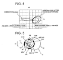
FIG. 4] Fig. 4 is a load diagram of a crankshaft concerned with a fourth embodiment, made according to the invention. - [
FIG. 5] Fig. 5 is a cross-sectional view illustrating the crankshaft of the fourth embodiment. - [
FIG. 6] Fig. 6 is a front elevation schematically illustrating a lower link and an upper link included in a multi-link mechanism concerned with a fifth embodiment, made according to the invention. - [
FIG. 7] Figs. 7A-7B are explanatory views illustrating a peripheral oil groove and a splash hole, formed in the lower link concerned with the fifth embodiment, at two different crankangles. - [
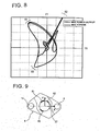
FIG. 8] Fig. 8 is a load diagram of a lower link concerned with a sixth embodiment, at a crankpin bearing portion. - [
FIG. 9] Fig. 9 is a front elevation illustrating the lower link concerned with the sixth embodiment. - [
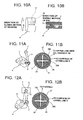
FIG. 10] Fig. 10A is a perspective view schematically illustrating a crankpin bearing portion concerned with a seventh embodiment, made according to the invention, andFig. 10B is a cross-section of the same. - [
FIG. 11] Fig. 11A is a front elevation illustrating a lower link and an upper link concerned with an eighth embodiment, made according to the invention, andFig. 11B is a cross-section of the lower link and the upper link, at a crankpin bearing portion. - [
FIG. 12] Fig. 12A is a front elevation illustrating a lower link and an upper link concerned with a sixth embodiment, made according to the invention, andFig. 12B is a cross-section of the lower link and the upper link, at a crankpin bearing portion. - [
FIG. 13] Fig. 13 is an assembled view schematically illustrating a multi-link piston-crank mechanism, made according to the invention. - [
FIG. 14] Fig. 14 is a disassembled view of the multi-link piston-crank mechanism ofFig. 13 . - [
FIG. 15] Fig. 15 is an explanatory view illustrating a position of formation of an oil-passage pin-side opening, common to all of the embodiments. - [
FIG. 16] Fig. 16 is an explanatory view illustrating a relation between a load caused by torsional torque and acting on a crankpin and a crankthrow. - [
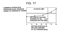
FIG. 17] Fig. 17 is an explanatory view illustrating a change in stress produced in an oil passage, in accordance with a change in the position of formation of a pin-side opening of the oil passage in a crank rotation direction. - The preferred embodiments of the invention are hereinafter described in reference to the drawings.
Figs. 13-14 are assembled/disassembled views schematically illustrating a multi-link piston-crank mechanism (simply, a multi-link mechanism) of an internal combustion engine to which a crankshaft of the invention is applied. Acylinder block 14 has a plurality of cylinders formed therein. Apiston 8 is slidably fitted in each of the cylinders. Amain journal 2 of acrankshaft 1 is rotatably supported on the cylinder block. - As described in the previously-noted
JP2008-224015 upper link 6 whose one end is linked to thepiston 8 via apiston pin 7, alower link 4 linked to the other end of theupper link 5 via anupper pin 6 and also linked to acrankpin 3 of thecrankshaft 1, and anauxiliary link 10, one end (the lower end) of the auxiliary link being pivotally supported on the side ofcylinder block 14, corresponding to a main-body side of the internal combustion engine, and the other end (the upper end) of the auxiliary link being linked to thelower link 4 via anauxiliary pin 11. Regardingcrankshaft 1,main journal 2 andcrankpin 3 are connected via acrank web 14. - Hereupon, L1 denotes a crankthrow from the axis of
main journal 2 to the axis ofcrankpin 3, L2 denotes a distance from the geometric center of the crankpin bearing portion oflower link 4 to the geometric center of the upper-pin bearing portion oflower link 4, L3 denotes a distance from the geometric center of the auxiliary-pin bearing portion ofauxiliary link 10 to the geometric center of aneccentric shaft portion 12B, L4 denotes a distance from the geometric center of the crankpin bearing portion oflower link 4 to the geometric center of the auxiliary-pin bearing portion oflower link 4, L6 denotes a distance from the geometric center of the piston-pin bearing portion ofupper link 5 to the geometric center of the upper-pin bearing portion ofupper link 5, and x4 denotes an offset amount of the center of piston pin 7 (reciprocating along a cylinder centerline) from the crankshaft main journal centerline. - As compared to a single-link mechanism in which a piston pin and a crankpin are connected by one connecting link, such a multi-link mechanism, in which
piston pin 7 andcrankpin 3 are connected via a plurality of links, has a higher degree of freedom of piston stroke characteristic settings. By optimizing the piston stroke characteristic, for instance, by tuning the piston stroke characteristic to a characteristic close to a simple harmonic oscillation, it is possible to remarkably attenuate noise and vibrations. - The previously-noted crankthrow L1 is set shorter than one-half of the (maximum) piston stroke. Hence, in comparison with a popular single-link mechanism in which a crankthrow is one-half of a piston stroke, in the case of the multi-link mechanism, for the same engine compression ratio, by virtue of the shortened crankthrow L1, it is possible to attain the enhanced rigidity and strength and downsizing. Also, for the same length of crankthrow L1, it is possible to attain high-compression-ratio engine. As a result of the shortened crankthrow, as viewed in the crank axial direction, the crankpin and the main journal are overlapped with each other. Thus, the crankshaft has such an overlapping area (denoted by ΔOL in
Fig. 1B ), in which the crankpin and the main journal are overlapped with each other in the decentering direction of the crankpin. - Furthermore, a
journal portion 12A ofauxiliary shaft 12, which extends continuously over the plurality of cylinders, is rotatably supported on thecylinder block 14 via support members (not shown).Auxiliary shaft 12 has the previously-discussedauxiliary shaft portion 12B provided for each engine cylinder. The other end ofauxiliary link 10 is pivotably linked to the associatedeccentric shaft portion 12B. Hence, by changing the rotational position ofauxiliary shaft 12 by means of an actuator (not shown) depending on engine operating conditions, the position ofeccentric shaft portion 12B, serving as a fulcrum of oscillating motion ofauxiliary link 10, can be changed, and therefore an engine compression ratio can be changed owing to a change in a motion-restriction condition that motion oflower link 4 is restricted by means of auxiliary link 10 (variable compression ratio means). As discussed above, it is possible to easily realize variable engine-compression-ratio control by the use of a multi-link piston-crank mechanism. - The specific construction, operation and effects of the embodiments are hereunder described in detail. As clearly shown in
Fig. 1 ,crankshaft 1 has anoil passage 20 formed therein, for supplying lubricating oil from the cylinder-block side to the crankpin bearing portion. One end ofoil passage 20, that is, a pin-side opening 21 is configured to be open at the outer peripheral surface ofcrankpin 3. - First of all, regarding the specific construction, common to all of the embodiments, as shown in
Fig. 15 , the oil-passage pin-side opening, configured to be open at the outer peripheral surface of the crankpin, is located and formed in either one of angular ranges P1-P4, substantially corresponding to 45 degrees, 135 degrees, 225 degrees, and 315 degrees in a crank rotation direction α (i.e., in a revolving direction ofcrankpin 3 about the main journal 2) with respect to a reference line X1 extending from the main journal toward the axis of the crankpin in the crankpin decentering direction X. That is, the center position of pin-side opening 21 is formed in either one of angular positions of 45 degrees, 135 degrees, 225 degrees, and 315 degrees, or formed in either one of angular ranges of 45°±10°, 135°±10°, 225°±10°, and 315°±10°. In other words, pin-side opening 21 is formed in ranges other than angular ranges Q1 and Q3 in which combustion load and/or inertial load acts in the crankpin decentering direction X, that is, angular ranges Q1 and Q3, substantially corresponding to 0° and 180° in the crank rotation direction α with respect to the reference line X1, or formed in ranges other than angular ranges Q2 and Q4 in which a load caused by torsional torque acts in the crankpin transverse direction Y, that is, angular ranges Q2 and Q4, substantially corresponding to 90° and 270° (-90°) in the crank rotation direction α with respect to the reference line X1. - As discussed above, in the crankshaft that crankthrow L1 is shortened by the use of the multi-link mechanism, assume that the pin-side opening is formed in angular ranges Q2 and Q4 in the crankpin transverse direction Y, that is, in angular ranges Q2 and Q4, corresponding to diametrically-opposing portions of both sides of the crankpin in the crankpin transverse direction. A stress concentration tends to occur in the vicinity of the pin-side opening owing to a load caused by torsional torque and acting in the crankpin transverse direction Y. Also, this leads to the difficulty of ensuring an oil film in the vicinity of the pin-side opening. Due to such an inadequate oil film (a lack of oil film), there is a tendency for the fluid-lubrication performance to be lowered. In the case of the multi-link mechanism, on the one hand, by virtue of the shortened crankthrow, the overlapping area ΔOL increases and thus the strength and rigidity thereof also increase. On the other hand, owing to the shortened crankthrow, the rigidity of the overlapping area of
crank web 14 for the load, caused by torsional moment and acting in the crankpin transverse direction perpendicular to both the crank axial direction and the crankpin decentering direction, tends to become locally high, and thus a stress concentration tends to be induced in the section other than the locally-high-rigidity section. Especially, a stress tends to concentrate in an oil passage formed to penetrate in the crankpin transverse direction. Therefore, by forming pin-side opening 21 in ranges other than angular ranges Q2 and Q4, corresponding to diametrically-opposing portions of both sides of the crankpin in the crankpin transverse direction, such a stress concentration can be suppressed and alleviated, thereby reducing the diameter of the crankpin, while ensuring a required strength and rigidity, and consequently achieving compactification. Additionally, it is possible to suppress a lack of oil film in the vicinity of the pin-side opening 21, thus enabling a good fluid-lubricating action. That is, the oil-passage opening on the side ofcrankpin 3 is formed in angular ranges in the crank rotation direction, in which a stress concentration cannot be produced in the oil passage without an inadequate oil film in the vicinity of pin-side opening 21 of oil passage (oil hole) 20.Fig. 17 shows a change in stress (a combined stress of a bending stress and a shearing stress) produced in the oil passage owing to torsion of the crankshaft in accordance with a change in the position of formation of the oil-passage pin-side opening in the internal combustion engine to which the multi-link piston-crank mechanism (the multi-link mechanism) shown inFig. 13 is applied. In the shown embodiment, the internal combustion engine is an in-line four-cylinder internal combustion engine of 1.6-L displacement, provided with a multi-link piston-crank mechanism and acrankshaft 1, which includescrankpins 3, each having a diameter of 35 millimeters and made of chromium molybdenum steel material, such as SCM440H. A distance (a leverage) from the center of the connecting pin ofcontrol link 10 andlower link 4 to the center of the connecting pin ofupper link 5 andlower link 4 is set to 1.9. As viewed in the axial direction ofcrankshaft 1,crankpin 3 is overlapped with themain journal 2 ofcrankshaft 1 by 22.8 millimeters in the crankpin decentering direction. When the setting position (the position of formation) of the oil-passage pin-side opening with respect to the reference line X1 exceeds 60 degrees, the stress (the combined stress of bending stress and shearing stress), produced in the oil passage owing to torsion (torsional oscillation), tends to exceed a fatigue limit (a critical stress), set based on a stress amplitude and a mean stress. For the reasons discussed above, the angular ranges Q2 and Q4 in the crankpin transverse direction Y, in which the oil-passage pin-side opening 21 should not be formed, substantially correspond to an angular range from 60 degrees to 120 degrees and an angular range from 240 degrees to 300 degrees. - Also, in angular ranges Q1 and Q3 in the crankpin decentering direction X, great combustion load and/or inertial load acts near the top dead center (TDC) and the bottom dead center (BDC). Thus, assuming that the pin-side opening is formed in angular ranges Q1 and Q3 in the crankpin decentering direction X, owing to the leverage of the multi-link mechanism, a further increased magnitude of combustion load/inertial load tends to repeatedly act on the pin-side opening near the piston TDC position and the piston BDC position of each engine cylinder. That is, as discussed previously, there is a risk of the occurrence of stress concentration and lowered fluid-lubrication performance arising from an inadequate oil film. In contrast to the above, when the pin-
side opening 21 is located and formed in ranges other than angular ranges Q1 and Q3 in which great combustion load and/or inertial load acts, the combustion load and/or inertial load never acts directly in the vicinity of the pin-side opening 21. Thus, it is possible to suppress a lack of oil film in the vicinity of the pin-side opening 21, while alleviating and reducing a stress concentration in the vicinity of the pin-side opening 21, thus enabling a good fluid-lubricating action. - The technical term "angle" described later, basically means an angle measured in the crank rotation direction α with respect to the reference line X1 extending from the crankpin center taken as an origin.
- In the first embodiment shown in
Figs. 1A-1B ,oil passage 20 is formed to straightly penetrate the inside ofcrankpin 3, crankweb 14, andmain journal 2 over the entire length from the pin-side opening 21, which is open at the outer peripheral surface ofcrankpin 3 to a journal-side opening 22, which is open at the outer peripheral surface ofmain journal 2. The previously-notedoil passage 20 is formed in the overlapping range ΔOL in whichcrankpin 3 andmain journal 2 are overlapped with each other in the crankpin decentering direction X. Concretely, the pin-side opening 21 is located and formed in either one of angular ranges, substantially corresponding to 135 degrees and 225 degrees in the crank rotation direction with respect to the reference line X1, whereas the journal-side opening 22 is located and formed in either one of angular ranges, substantially corresponding to 315 degrees and 45 degrees in the crank rotation direction with respect to the reference line X1. That is,oil passage 20 is arranged within the overlapping range ΔOL and formed in ranges other than angular ranges Q1-Q4 (seeFig. 15 ), in which a large magnitude of load acts, in a manner so as to obliquely penetrate straight, as viewed in the crank axial direction. This contributes to a comparatively short entire oil-passage length as well as easy machining. InFigs. 1A-1B , for the purpose of clarification, each of the openings are exaggeratedly shown such that the inside diameter of each of openings 21-22 is greater than that ofoil passage 20, but actually,oil passage 20 is formed as a through hole having the same cross-section as each of the openings 21-22. - As discussed previously, in comparison with a single-link mechanism, in the case of the multi-link mechanism, by virtue of the shortened crank-arm (shortened crankthrow L1), the overlapping area ΔOL increases and thus the strength and rigidity thereof also increase. Hence, it is possible to easily form the previously-noted
oil passage 20 by way of which the outer peripheries ofmain journal 2 andcrankpin 3 are connected each other straightly and directly. Additionally, by forming theoil passage 20 within the overlapping range ΔOL, there is a less risk of reducing the strength and rigidity owing to formation ofoil passage 20. Furthermore, machining thestraight oil passage 20 eliminates the need for forming additional radial oil passages in the crankpin and/or the main journal. This contributes to the reduced machining time and costs, and also ensures a required strength and rigidity. - In the second embodiment shown in
Fig. 2 , as a part ofoil passage 20, aradial oil passage 24 is further formed to penetratecrankpin 3 in the diametral direction of the crankpin.Radial oil passage 24 has two opposite openings, which are open at the outer peripheral surface ofcrankpin 3, namely, the first pin-side opening 24A located and formed in an angular range substantially corresponding to 135 degrees, and the second pin-side opening 24B located and formed in an angular range substantially corresponding to 315 degrees. Lubricating oil is supplied from the cylinder-block side via another oil passage (not shown) formed in the crankshaft to theradial oil passage 24, and then further delivered through the pin-side openings 24A-24B to the crankpin bearing portion. - According to the second embodiment,
radial oil passage 24 is formed to straightly penetratecrankpin 3 in the diametral direction of the crankpin, thus facilitating machining. Additionally, oil can be supplied to the crankpin bearing portion through the two opposite pin-side openings 24A-24B of both ends ofradial oil passage 24, thus resulting in an increase in the lubricating-oil amount. - In ta similar manner to the second embodiment, in the third embodiment shown in
Fig. 3 , as a part ofoil passage 20, aradial oil passage 25 is further formed to penetratecrankpin 3 in the diametral direction of the crankpin. Lubricating oil is supplied from the cylinder-block side via another oil passage (not shown) formed in the crankshaft to theradial oil passage 25, and then further delivered through pin-side openings 25A-25B to the crankpin bearing portion. The third embodiment differs from the second embodiment, in that the first pin-side opening 25A ofradial oil passage 25, which is open at the outer peripheral surface ofcrankpin 3, is located and formed in an angular range substantially corresponding to 45 degrees around the crankpin, and the second pin-side opening 25B, which is open at the outer peripheral surface ofcrankpin 3, is located and formed in an angular range substantially corresponding to 225 degrees around the crankpin. - By the way, in the internal combustion engine having the multi-link mechanism, the crankangle, corresponding to the piston TDC position, tends to phase-retard with respect to the reference position of revolution of the crankshaft (exactly, the crankangle at which the crankpin decentering direction X is identical to the crankshaft main journal centerline). As seen from the load diagram of
Fig. 4 , combustion load acting from the crankpin side toward the main journal side, tends to act in an angular range substantially corresponding to an angle displaced from the reference position of revolution of the crankshaft in the direction (i.e., in the clockwise direction) opposite to the crank rotation direction, that is, in an angular range substantially corresponding to 315 degrees (-45 degrees). - As compared to the second embodiment, the third embodiment is superior for the reasons discussed below. That is, in the third embodiment,
radial oil passage 25 is formed to be obliquely inclined by 45 degrees in the crank rotation direction with respect to the crankpin decentering direction X, such that the pin-side openings 25A-25B are formed in the respective angular ranges, substantially corresponding to 45 degrees and 225 degrees. Thus, it is possible to suppress or alleviate the openings from being affected by combustion load acting in the angular range substantially corresponding to 315 degrees (-45 degrees). - In the fourth embodiment shown in
Fig. 5 , the crankpin has two radial oil passages 24-25, each formed to penetratecrankpin 3 in the diametral direction of the crankpin. In a similar manner to the second embodiment, the two opposite pin-side openings 24A-24B of the firstradial oil passage 24, which are open at the outer peripheral surface ofcrankpin 3, are located and formed in respective angular ranges substantially corresponding to 135 degrees and 315 degrees. In a similar manner to the third embodiment, the two opposite pin-side openings 25A-25B of the secondradial oil passage 25, which are open at the outer peripheral surface ofcrankpin 3, are located and formed in respective angular ranges substantially corresponding to 45 degrees and 225 degrees. In the fourth embodiment, four pin-side openings crankpin 3, thereby enabling a further increase in the amount of lubricating oil supplied to the crankpin bearing portion. - Referring to
Figs. 6, and Figs. 7A-7B , there are shown the oil-passage structure of the lower-link side of the fifth embodiment, utilizing the crankshaft-side oil-passage structure well. By the provision of the two radial oil passages 24-25 formed incrankpin 3, four pin-side openings crankpin 3 in a manner so as to be circumferentially equidistant-spaced from each other, that is, in a manner so as to be open every predetermined angular intervals, such as 90 degrees. - Also,
lower link 4 has aperipheral oil groove 27 and asplash hole 28 formed therein.Peripheral oil groove 27 is formed as a radially-outward recessed groove in the crankpin bearing surface oflower link 4 in a manner so as to extend in the peripheral direction over an angular range of 90 degrees.Splash hole 28 is provided to inject and supply lubricating oil toward a designated bearing portion, that is, the bearing portion ofupper pin 6 in the fifth embodiment. One opening end ofsplash hole 28 is configured to open into the bottom face ofperipheral oil groove 27, whereas the other opening end ofsplash hole 28 is configured to open into the bottom face of the forked pin-boss portion that supports theupper pin 6. Thus, lubricating oil, supplied fromperipheral oil groove 27 to splashhole 28, can be injected and fed toward the upper-pin side (upper pin 6). - In this manner, four pin-
side openings crankpin 3 in a manner so as to be circumferentially equidistant-spaced from each other every predetermined angular intervals, such as 90 degrees.Peripheral oil groove 27 is circumferentially recessed in the lower-link side (lower link 4) over the same angular range (i.e., 90 degrees) as the angular interval between the two adjacent openings of these pin-side openings side openings peripheral oil groove 27 in a manner so as to be brought into fluid-communication with theperipheral oil groove 27. For instance, at given degrees of crankangle shown inFig. 7A , the pin-side opening 24B is brought into fluid-communication with theperipheral oil groove 27. Thereafter, when the crankshaft further rotates given degrees of crankangle, as shown inFig. 7A , the pin-side opening 25B is brought into fluid-communication with theperipheral oil groove 27. In this manner, regardless of the crankangle, lubricating oil can be supplied from either one of pin-side openings peripheral oil groove 27 and then injected and delivered throughsplash hole 28 into the upper-pin side. Thus, it is possible to increase the feed rate of lubricating oil toward the upper-pin side, thereby enhancing the fluid-lubrication performance and the cooling performance by virtue of oil spray/splash. - More preferably, a radially-penetrating upper-link
side oil passage 29 may be formed in the pin-bearing portion ofupper link 5 forupper pin 6, in a manner so as to be oriented substantially in the oil-splay direction ofsplash hole 28, and hence part of lubricating oil splayed fromsplash hole 28 can be more certainly supplied through the upper-linkside oil passage 29 to the upper-pin bearing portion (upper pin 6). - Referring to
Fig. 8 , there is shown the load diagram for the crankpin bearing portion. As seen from this load diagram, load, acting on the crankpin bearing portion oflower link 4, tends to become high locally at predetermined angular ranges R1, R2, and R3. Therefore, in the sixth embodiment ofFig. 9 ,peripheral oil groove 27 is formed in ranges of the crankpin bearing portion other than the above-mentioned angular ranges R1, R2, and R3, in which a large magnitude of load acts. Concretely,peripheral oil groove 27 is formed in a 90° angular range whose center is an angular position intersecting with the direction X directed from the axis of the crankpin bearing portion of the lower link toward the axis of the upper-pin bearing portion (upper pin 6) of the lower link. Hence, it is possible to avoid three great loads, namely, combustion load, inertial load at the piston TDC position, and inertial load at the piston BDC position from acting directly on theperipheral oil groove 27. - In the seventh embodiment shown in
Figs. 10A-10B , an oil-sump portion 30 is formed in the crankpin bearing surface oflower link 4 as a recessed portion extending in the axial direction of the crankpin. Oil-sump portion 30 is connected to the upstream-side end ofperipheral oil groove 27 in the direction of sliding motion of the bearing portion (i.e., in the rotation direction of the crankpin bearing portion of lower link 4). Additionally, the oil-sump portion is formed to extend to the vicinity of each axial end of the crankpin bearing portion oflower link 4. However, oil-sump portion 30 is closed at both ends without extending to each axial end of the crankpin bearing portion oflower link 4. - With the previously-discussed oil-passage structure, lubricating oil, supplied from the crankpin-side (crankpin 3) oil passage to
peripheral oil groove 27 oflower link 4, can be delivered into the oil-sump portion 30 by virtue of rotation ofcrankpin 3. Additionally, due to a shearing stress arising from viscosity, part of lubricating oil is flown out in such a manner as to be dragged in the direction of sliding motion of the crankpin (i.e., in the rotation direction ofcrankpin 3 relative to the crankpin bearing portion of lower link 4), that is, in the direction opposite to the direction of sliding motion of the crankpin bearing portion, thus ensuring stable supply of lubricating oil to the crankpin bearing portion. - By the way, oil-
sump portion 30 is formed in ranges of the crankpin bearing surface other than the above-mentioned angular ranges R1, R2, and R3, in which a large magnitude of load acts, for example, in either one of angular ranges, substantially corresponding to 0°, 90°, 180° and 315°. Hence, it is possible to avoid a large magnitude of load from acting directly on the oil-sump portion 30. - In the eighth embodiment shown in
Figs. 11A-11B ,lower link 4 has twosplash holes peripheral oil groove 27. Thefirst splash hole 28A is provided to inject and supply lubricating oil mainly toward the bearing surface of the upper-pin bearing portion ofupper link 5, whereas thesecond splash hole 28B is provided to inject and supply lubricating oil mainly toward the upper-link side oil passage 29 (seeFig. 6 ) formed in the pin-bearing portion ofupper link 5 forupper pin 6. - In the ninth embodiment shown inn
Figs. 12A-12B ,lower link 4 has twosplash holes peripheral oil groove 27. Thefirst splash hole 28A is provided to inject and supply lubricating oil mainly toward the bearing surface of the upper-pin bearing portion ofupper link 5, whereas thesecond splash hole 28C is provided to inject and supply lubricating oil mainly toward thepiston 8 for the purpose of cooling thepiston 8 and also lubricating the piston-pin bearing portion. - As appreciated from the eighth and ninth embodiments, by virtue of a plurality of splash holes 28 formed in
lower link 4, it is possible to effectively inject and supply lubricating oil toward a plurality of moving parts to be lubricated and cooled. -
- 1
- ··· CRANKSHAFT
- 2
- ··· MAIN JOURNAL
- 3
- ··· CRANKPIN
- 4
- ··· LOWER LINK
- 5
- ··· UPPER LINK
- 6
- ··· UPPER PIN
- 7
- ··· PISTON PIN
- 8
- ··· PISTON
- 10
- ··· AUXILIARY LINK
- 11
- ··· AUXILIARY PIN
- 20
- ··· OIL PASSAGE
- 21
- ··· PIN-SIDE OPENING
- 22
- ··· JOURNAL-SIDE OPENING
- 24, 25
- ··· RADIAL OIL PASSAGES
- 24A, 24B, 25A, 25B
- ··· PIN-SIDE OPENINGS
- 27
- ··· PERIPHERAL OIL GROOVE
- 28
- ··· SPLASH HOLE
- X
- ··· CRANKPIN DECENTERING DIRECTION
- Y
- ··· CRANKPIN TRANSVERSE DIRECTION
Claims (7)
- A crankshaft of an internal combustion engine provided with a multi-link piston-crank mechanism having an upper link whose one end is linked to a piston via a piston pin, a lower link linked to the other end of the upper link via an upper pin and linked to a crankpin of the crankshaft, and an auxiliary link, one end of the auxiliary link being pivotally supported on a main-body side of the engine, and the other end of the auxiliary link being linked to the lower link via an auxiliary pin, comprising:an oil passage formed in the crankshaft for supplying lubricating oil to a bearing portion of the crankpin,wherein a crankthrow from an axis of a main journal of the crankshaft to an axis of the crankpin is set shorter than one-half of a stroke of the piston, and, as viewed in an axial direction of the crankshaft, the crankpin and the main journal are overlapped with each other, andwherein a pin-side opening of the oil passage, which is open at an outer peripheral surface of the crankpin, is formed in angular ranges other than angular ranges of 90° and -90° with respect to a reference line extending from the axis of the main journal toward the axis of the crankpin in a decentering direction of the crankpin.
- A crankshaft of an internal combustion engine provided with a multi-link piston-crank mechanism, as claimed in claim 1, wherein:the pin-side opening is formed in the angular ranges other than angular ranges located in the crankpin decentering direction.
- A crankshaft of an internal combustion engine provided with a multi-link piston-crank mechanism, as claimed in claims 1 or 2, wherein:the oil passage is formed to straightly penetrate over an entire length from the pin-side opening to a journal-side opening, which is open at an outer peripheral surface of the main journal.
- A crankshaft of an internal combustion engine provided with a multi-link piston-crank mechanism, as claimed in claim 3, wherein:the oil passage is formed in an overlapping range in which the crankpin and the main journal are overlapped with each other in the crankpin decentering direction.
- A crankshaft of an internal combustion engine provided with a multi-link piston-crank mechanism, as claimed in claims 1 or 2, wherein:the oil passage further includes a radial oil passage formed to straightly penetrate the crankpin in a diametral direction of the crankpin.
- A crankshaft of an internal combustion engine provided with a multi-link piston-crank mechanism, as claimed in claim 5, wherein:the pin-side openings are formed in respective angular ranges of 45° and 225° in a crank rotation direction with respect to the reference line.
- A crankshaft of an internal combustion engine provided with a multi-link piston-crank mechanism, as claimed in any one of preceding claims 1 to 5, wherein:a plurality of pin-side openings are formed in the outer peripheral surface of the crankpin in a manner so as to be circumferentially equidistant-spaced from each other;a peripheral groove is formed in a crankpin bearing surface of the lower link in a manner so as to extend circumferentially;a splash hole is formed in the lower link to inject and supply lubricating oil toward a designated bearing portion, one opening end of the splash hole being configured to open into the peripheral oil groove and the other opening end being directed toward the designated bearing portion; andthe peripheral oil groove is formed to circumferentially extend over the same angular range as an angular interval between the two adjacent pin-side openings.
Applications Claiming Priority (2)
| Application Number | Priority Date | Filing Date | Title |
|---|---|---|---|
| JP2009168674 | 2009-07-17 | ||
| PCT/JP2010/059247 WO2011007622A1 (en) | 2009-07-17 | 2010-06-01 | Crankshaft of internal combustion engine provided with multi link-type piston-crank mechanism and multi link-type piston-crank mechanism of internal combustion engine |
Publications (3)
| Publication Number | Publication Date |
|---|---|
| EP2463498A1 true EP2463498A1 (en) | 2012-06-13 |
| EP2463498A4 EP2463498A4 (en) | 2013-05-29 |
| EP2463498B1 EP2463498B1 (en) | 2016-07-20 |
Family
ID=43449231
Family Applications (1)
| Application Number | Title | Priority Date | Filing Date |
|---|---|---|---|
| EP10799684.5A Active EP2463498B1 (en) | 2009-07-17 | 2010-06-01 | Multi-link piston-crank mechanism |
Country Status (5)
| Country | Link |
|---|---|
| US (1) | US20120111143A1 (en) |
| EP (1) | EP2463498B1 (en) |
| JP (1) | JP5252083B2 (en) |
| CN (1) | CN102482995B (en) |
| WO (1) | WO2011007622A1 (en) |
Cited By (2)
| Publication number | Priority date | Publication date | Assignee | Title |
|---|---|---|---|---|
| RU2624081C1 (en) * | 2013-06-20 | 2017-06-30 | Ниссан Мотор Ко., Лтд. | Load-carrying structure for multi-link crank mechanism in internal combustion engines |
| EP4215724A4 (en) * | 2020-09-15 | 2023-11-01 | Nissan Motor Co., Ltd. | SUBSTITUTE OF AN INTERNAL COMBUSTION ENGINE |
Families Citing this family (19)
| Publication number | Priority date | Publication date | Assignee | Title |
|---|---|---|---|---|
| JP5251576B2 (en) * | 2009-02-12 | 2013-07-31 | 日産自動車株式会社 | Double link piston crank mechanism for internal combustion engine |
| DE102012005118B4 (en) * | 2012-03-14 | 2014-12-11 | Audi Ag | Multi-joint crank drive of an internal combustion engine |
| DE102012020027A1 (en) | 2012-10-12 | 2013-05-02 | Daimler Ag | Reciprocating piston internal combustion engine for passenger car, has lever element pivoted at bearing position at crank pin, where one bearing position is designed for supplying lubricant to other bearing position from lubrication mist |
| MX348563B (en) * | 2013-02-20 | 2017-06-20 | Nissan Motor | Variable compression ratio internal combustion engine. |
| WO2015025683A1 (en) * | 2013-08-22 | 2015-02-26 | 日産自動車株式会社 | Double-link piston crank mechanism for internal combustion engine |
| JP5983887B2 (en) * | 2013-08-27 | 2016-09-07 | 日産自動車株式会社 | Double link piston crank mechanism for internal combustion engine |
| WO2016042605A1 (en) * | 2014-09-17 | 2016-03-24 | 日産自動車株式会社 | Internal combustion engine |
| RU2665828C1 (en) * | 2014-12-22 | 2018-09-04 | Тойота Дзидося Кабусики Кайся | Variable-length connecting rod and variable-compression internal combustion engine |
| CA2973535C (en) * | 2015-01-15 | 2018-01-23 | Nissan Motor Co., Ltd. | Double-link piston crank mechanism for internal combustion engine |
| JP6277997B2 (en) * | 2015-05-15 | 2018-02-14 | トヨタ自動車株式会社 | Internal combustion engine |
| WO2017037935A1 (en) * | 2015-09-04 | 2017-03-09 | 日産自動車株式会社 | Lubrication structure and lubrication method for upper pin in piston crank mechanism of internal combustion engine |
| JP6132057B2 (en) * | 2016-06-27 | 2017-05-24 | 日産自動車株式会社 | Lubrication structure of a multi-link piston-crank mechanism of an internal combustion engine |
| DE102016212466A1 (en) * | 2016-07-08 | 2018-01-11 | Schaeffler Technologies AG & Co. KG | Arrangement for transmitting a pressure medium |
| JP7168404B2 (en) * | 2018-10-01 | 2022-11-09 | 株式会社ジャパンエンジンコーポレーション | Crosshead and crosshead internal combustion engines |
| US11143066B2 (en) * | 2019-01-02 | 2021-10-12 | GM Global Technology Operations LLC | Crankshaft assembly with oiling scheme |
| US11313409B1 (en) * | 2019-12-19 | 2022-04-26 | Brunswick Corporation | Crankshaft and cranktrain for internal combustion engine |
| US11549549B2 (en) * | 2021-06-15 | 2023-01-10 | GM Global Technology Operations LLC | Engine crankshaft assemblies with internal stiffening structures |
| CN118640085B (en) * | 2024-07-02 | 2025-09-19 | 一汽解放汽车有限公司 | Piston cooling nozzle structure and engine |
| CN119308757A (en) * | 2024-09-29 | 2025-01-14 | 吉林大学 | A two-stroke heavy oil aviation piston engine |
Family Cites Families (17)
| Publication number | Priority date | Publication date | Assignee | Title |
|---|---|---|---|---|
| US2419408A (en) * | 1943-11-15 | 1947-04-22 | Maudslay Motor Company Ltd | Crankshaft |
| CH501849A (en) * | 1968-12-24 | 1971-01-15 | Sulzer Ag | Crankshaft of a four-stroke piston internal combustion engine |
| GB1355820A (en) * | 1971-12-30 | 1974-06-05 | Ricardo & Co Engineers | Piston cooling and or small-end bearing lubrication arrangement for ic engines |
| US3785459A (en) * | 1972-05-11 | 1974-01-15 | Allis Chalmers | Lubrication and cooling system for connecting rod and piston |
| DE2647441A1 (en) * | 1976-10-21 | 1978-04-27 | Kloeckner Humboldt Deutz Ag | ARRANGEMENT FOR LUBRICATING A CRANK PIN BEARING |
| JP2730276B2 (en) * | 1990-07-13 | 1998-03-25 | トヨタ自動車株式会社 | Piston cooling structure for internal combustion engine |
| US5152373A (en) * | 1991-07-19 | 1992-10-06 | Callies Performance Products | Crankshaft lubricating system |
| US5163341A (en) * | 1991-10-08 | 1992-11-17 | General Motors Corporation | Crankshaft with lubrication passages |
| JPH1130223A (en) * | 1997-07-14 | 1999-02-02 | Nissan Motor Co Ltd | Oiling structure of crankshaft of internal combustion engine |
| JP2000081022A (en) * | 1998-09-04 | 2000-03-21 | Nissan Motor Co Ltd | Internal combustion engine lubrication system |
| DE10105542A1 (en) * | 2001-02-07 | 2002-08-29 | Porsche Ag | Lube oil supply for the connecting rod bearings of a crankshaft of a multi-cylinder internal combustion engine |
| JP3882643B2 (en) * | 2001-04-05 | 2007-02-21 | 日産自動車株式会社 | Variable compression ratio mechanism of internal combustion engine |
| JP4092495B2 (en) * | 2003-08-28 | 2008-05-28 | 日産自動車株式会社 | Double link type piston-crank mechanism for internal combustion engine |
| EP1602840B1 (en) * | 2004-06-04 | 2011-08-24 | Honda Motor Co., Ltd. | Assembled crankshaft |
| JP4395051B2 (en) * | 2004-11-08 | 2010-01-06 | 本田技研工業株式会社 | Lubricating oil supply structure |
| CN200955418Y (en) * | 2006-06-27 | 2007-10-03 | 奇瑞汽车有限公司 | Automobile engine lubrication system |
| JP4646879B2 (en) * | 2006-09-08 | 2011-03-09 | 本田技研工業株式会社 | Variable stroke characteristics engine |
-
2010
- 2010-06-01 WO PCT/JP2010/059247 patent/WO2011007622A1/en not_active Ceased
- 2010-06-01 US US13/383,744 patent/US20120111143A1/en not_active Abandoned
- 2010-06-01 EP EP10799684.5A patent/EP2463498B1/en active Active
- 2010-06-01 JP JP2011522759A patent/JP5252083B2/en active Active
- 2010-06-01 CN CN201080031471.9A patent/CN102482995B/en active Active
Cited By (2)
| Publication number | Priority date | Publication date | Assignee | Title |
|---|---|---|---|---|
| RU2624081C1 (en) * | 2013-06-20 | 2017-06-30 | Ниссан Мотор Ко., Лтд. | Load-carrying structure for multi-link crank mechanism in internal combustion engines |
| EP4215724A4 (en) * | 2020-09-15 | 2023-11-01 | Nissan Motor Co., Ltd. | SUBSTITUTE OF AN INTERNAL COMBUSTION ENGINE |
Also Published As
| Publication number | Publication date |
|---|---|
| CN102482995A (en) | 2012-05-30 |
| US20120111143A1 (en) | 2012-05-10 |
| JPWO2011007622A1 (en) | 2012-12-27 |
| CN102482995B (en) | 2014-05-28 |
| WO2011007622A1 (en) | 2011-01-20 |
| JP5252083B2 (en) | 2013-07-31 |
| EP2463498B1 (en) | 2016-07-20 |
| EP2463498A4 (en) | 2013-05-29 |
Similar Documents
| Publication | Publication Date | Title |
|---|---|---|
| EP2463498B1 (en) | Multi-link piston-crank mechanism | |
| US6546900B2 (en) | Variable compression ratio mechanism for reciprocating internal combustion engine | |
| EP1247960B1 (en) | Variable compression ratio mechanism for reciprocating internal combustion engine | |
| JP5298911B2 (en) | Double link piston crank mechanism for internal combustion engine | |
| EP1950390A1 (en) | Engine with variable stroke characteristics | |
| EP1835146B1 (en) | Piston crank mechanism | |
| JP5304187B2 (en) | Double link piston crank mechanism for internal combustion engine | |
| JP5218305B2 (en) | Crankshaft of an internal combustion engine having a multi-link type piston-crank mechanism | |
| EP1674692B1 (en) | Internal combustion engine | |
| US9856907B2 (en) | Double-link piston crank mechanism for internal combustion engine | |
| US8826882B2 (en) | Lubricating structure of multi-link piston-crank mechanism for internal combustion engine | |
| JP2016196888A (en) | Lubrication structure of a multi-link piston-crank mechanism of an internal combustion engine | |
| US10184395B2 (en) | Multi-joint crank drive of an internal combustion engine, and corresponding internal combustion engine | |
| US20160053715A1 (en) | Internal combustion engine | |
| EP2025894A2 (en) | Internal combustion engine | |
| JP2010216633A (en) | Radial sliding bearing | |
| CN105745418A (en) | Multi-joint crank drive of an internal combustion engine and corresponding internal combustion engine | |
| WO2015025684A1 (en) | Internal combustion engine | |
| EP4215724B1 (en) | Lower link of internal combustion engine | |
| JP4581675B2 (en) | Internal combustion engine | |
| JP5321148B2 (en) | Double link variable compression ratio internal combustion engine | |
| JP2021006711A (en) | Expansion/compression stroke ratio, compression ratio continuously variable device | |
| JP2019167945A (en) | Three-divided connecting rod type stroke volume and compression ratio continuous variable device | |
| JP2013032853A (en) | Bearing structure of link mechanism | |
| JP2006177470A (en) | Crankshaft of internal combustion engine |
Legal Events
| Date | Code | Title | Description |
|---|---|---|---|
| PUAI | Public reference made under article 153(3) epc to a published international application that has entered the european phase |
Free format text: ORIGINAL CODE: 0009012 |
|
| 17P | Request for examination filed |
Effective date: 20120117 |
|
| AK | Designated contracting states |
Kind code of ref document: A1 Designated state(s): AL AT BE BG CH CY CZ DE DK EE ES FI FR GB GR HR HU IE IS IT LI LT LU LV MC MK MT NL NO PL PT RO SE SI SK SM TR |
|
| DAX | Request for extension of the european patent (deleted) | ||
| A4 | Supplementary search report drawn up and despatched |
Effective date: 20130502 |
|
| RIC1 | Information provided on ipc code assigned before grant |
Ipc: F01M 1/06 20060101ALI20130424BHEP Ipc: F01M 1/08 20060101ALI20130424BHEP Ipc: F02B 75/04 20060101ALI20130424BHEP Ipc: F02B 75/32 20060101AFI20130424BHEP |
|
| 17Q | First examination report despatched |
Effective date: 20150625 |
|
| REG | Reference to a national code |
Ref country code: DE Ref legal event code: R079 Ref document number: 602010034916 Country of ref document: DE Free format text: PREVIOUS MAIN CLASS: F02B0075320000 Ipc: F16C0003140000 |
|
| GRAP | Despatch of communication of intention to grant a patent |
Free format text: ORIGINAL CODE: EPIDOSNIGR1 |
|
| RIC1 | Information provided on ipc code assigned before grant |
Ipc: F02F 7/00 20060101ALI20160120BHEP Ipc: F02B 75/04 20060101ALI20160120BHEP Ipc: F16C 3/14 20060101AFI20160120BHEP |
|
| INTG | Intention to grant announced |
Effective date: 20160215 |
|
| GRAS | Grant fee paid |
Free format text: ORIGINAL CODE: EPIDOSNIGR3 |
|
| GRAA | (expected) grant |
Free format text: ORIGINAL CODE: 0009210 |
|
| AK | Designated contracting states |
Kind code of ref document: B1 Designated state(s): AL AT BE BG CH CY CZ DE DK EE ES FI FR GB GR HR HU IE IS IT LI LT LU LV MC MK MT NL NO PL PT RO SE SI SK SM TR |
|
| REG | Reference to a national code |
Ref country code: GB Ref legal event code: FG4D |
|
| REG | Reference to a national code |
Ref country code: CH Ref legal event code: EP |
|
| REG | Reference to a national code |
Ref country code: IE Ref legal event code: FG4D |
|
| REG | Reference to a national code |
Ref country code: AT Ref legal event code: REF Ref document number: 814355 Country of ref document: AT Kind code of ref document: T Effective date: 20160815 |
|
| REG | Reference to a national code |
Ref country code: DE Ref legal event code: R096 Ref document number: 602010034916 Country of ref document: DE |
|
| REG | Reference to a national code |
Ref country code: LT Ref legal event code: MG4D |
|
| REG | Reference to a national code |
Ref country code: NL Ref legal event code: MP Effective date: 20160720 |
|
| REG | Reference to a national code |
Ref country code: AT Ref legal event code: MK05 Ref document number: 814355 Country of ref document: AT Kind code of ref document: T Effective date: 20160720 |
|
| PG25 | Lapsed in a contracting state [announced via postgrant information from national office to epo] |
Ref country code: IT Free format text: LAPSE BECAUSE OF FAILURE TO SUBMIT A TRANSLATION OF THE DESCRIPTION OR TO PAY THE FEE WITHIN THE PRESCRIBED TIME-LIMIT Effective date: 20160720 Ref country code: LT Free format text: LAPSE BECAUSE OF FAILURE TO SUBMIT A TRANSLATION OF THE DESCRIPTION OR TO PAY THE FEE WITHIN THE PRESCRIBED TIME-LIMIT Effective date: 20160720 Ref country code: IS Free format text: LAPSE BECAUSE OF FAILURE TO SUBMIT A TRANSLATION OF THE DESCRIPTION OR TO PAY THE FEE WITHIN THE PRESCRIBED TIME-LIMIT Effective date: 20161120 Ref country code: NO Free format text: LAPSE BECAUSE OF FAILURE TO SUBMIT A TRANSLATION OF THE DESCRIPTION OR TO PAY THE FEE WITHIN THE PRESCRIBED TIME-LIMIT Effective date: 20161020 Ref country code: NL Free format text: LAPSE BECAUSE OF FAILURE TO SUBMIT A TRANSLATION OF THE DESCRIPTION OR TO PAY THE FEE WITHIN THE PRESCRIBED TIME-LIMIT Effective date: 20160720 Ref country code: FI Free format text: LAPSE BECAUSE OF FAILURE TO SUBMIT A TRANSLATION OF THE DESCRIPTION OR TO PAY THE FEE WITHIN THE PRESCRIBED TIME-LIMIT Effective date: 20160720 Ref country code: HR Free format text: LAPSE BECAUSE OF FAILURE TO SUBMIT A TRANSLATION OF THE DESCRIPTION OR TO PAY THE FEE WITHIN THE PRESCRIBED TIME-LIMIT Effective date: 20160720 |
|
| PG25 | Lapsed in a contracting state [announced via postgrant information from national office to epo] |
Ref country code: PT Free format text: LAPSE BECAUSE OF FAILURE TO SUBMIT A TRANSLATION OF THE DESCRIPTION OR TO PAY THE FEE WITHIN THE PRESCRIBED TIME-LIMIT Effective date: 20161121 Ref country code: ES Free format text: LAPSE BECAUSE OF FAILURE TO SUBMIT A TRANSLATION OF THE DESCRIPTION OR TO PAY THE FEE WITHIN THE PRESCRIBED TIME-LIMIT Effective date: 20160720 Ref country code: BE Free format text: LAPSE BECAUSE OF FAILURE TO SUBMIT A TRANSLATION OF THE DESCRIPTION OR TO PAY THE FEE WITHIN THE PRESCRIBED TIME-LIMIT Effective date: 20160720 Ref country code: GR Free format text: LAPSE BECAUSE OF FAILURE TO SUBMIT A TRANSLATION OF THE DESCRIPTION OR TO PAY THE FEE WITHIN THE PRESCRIBED TIME-LIMIT Effective date: 20161021 Ref country code: AT Free format text: LAPSE BECAUSE OF FAILURE TO SUBMIT A TRANSLATION OF THE DESCRIPTION OR TO PAY THE FEE WITHIN THE PRESCRIBED TIME-LIMIT Effective date: 20160720 Ref country code: LV Free format text: LAPSE BECAUSE OF FAILURE TO SUBMIT A TRANSLATION OF THE DESCRIPTION OR TO PAY THE FEE WITHIN THE PRESCRIBED TIME-LIMIT Effective date: 20160720 Ref country code: SE Free format text: LAPSE BECAUSE OF FAILURE TO SUBMIT A TRANSLATION OF THE DESCRIPTION OR TO PAY THE FEE WITHIN THE PRESCRIBED TIME-LIMIT Effective date: 20160720 Ref country code: PL Free format text: LAPSE BECAUSE OF FAILURE TO SUBMIT A TRANSLATION OF THE DESCRIPTION OR TO PAY THE FEE WITHIN THE PRESCRIBED TIME-LIMIT Effective date: 20160720 |
|
| REG | Reference to a national code |
Ref country code: DE Ref legal event code: R097 Ref document number: 602010034916 Country of ref document: DE |
|
| PG25 | Lapsed in a contracting state [announced via postgrant information from national office to epo] |
Ref country code: RO Free format text: LAPSE BECAUSE OF FAILURE TO SUBMIT A TRANSLATION OF THE DESCRIPTION OR TO PAY THE FEE WITHIN THE PRESCRIBED TIME-LIMIT Effective date: 20160720 Ref country code: EE Free format text: LAPSE BECAUSE OF FAILURE TO SUBMIT A TRANSLATION OF THE DESCRIPTION OR TO PAY THE FEE WITHIN THE PRESCRIBED TIME-LIMIT Effective date: 20160720 |
|
| REG | Reference to a national code |
Ref country code: FR Ref legal event code: PLFP Year of fee payment: 8 |
|
| PLBE | No opposition filed within time limit |
Free format text: ORIGINAL CODE: 0009261 |
|
| STAA | Information on the status of an ep patent application or granted ep patent |
Free format text: STATUS: NO OPPOSITION FILED WITHIN TIME LIMIT |
|
| PG25 | Lapsed in a contracting state [announced via postgrant information from national office to epo] |
Ref country code: DK Free format text: LAPSE BECAUSE OF FAILURE TO SUBMIT A TRANSLATION OF THE DESCRIPTION OR TO PAY THE FEE WITHIN THE PRESCRIBED TIME-LIMIT Effective date: 20160720 Ref country code: BG Free format text: LAPSE BECAUSE OF FAILURE TO SUBMIT A TRANSLATION OF THE DESCRIPTION OR TO PAY THE FEE WITHIN THE PRESCRIBED TIME-LIMIT Effective date: 20161020 Ref country code: SK Free format text: LAPSE BECAUSE OF FAILURE TO SUBMIT A TRANSLATION OF THE DESCRIPTION OR TO PAY THE FEE WITHIN THE PRESCRIBED TIME-LIMIT Effective date: 20160720 Ref country code: CZ Free format text: LAPSE BECAUSE OF FAILURE TO SUBMIT A TRANSLATION OF THE DESCRIPTION OR TO PAY THE FEE WITHIN THE PRESCRIBED TIME-LIMIT Effective date: 20160720 Ref country code: SM Free format text: LAPSE BECAUSE OF FAILURE TO SUBMIT A TRANSLATION OF THE DESCRIPTION OR TO PAY THE FEE WITHIN THE PRESCRIBED TIME-LIMIT Effective date: 20160720 |
|
| 26N | No opposition filed |
Effective date: 20170421 |
|
| PG25 | Lapsed in a contracting state [announced via postgrant information from national office to epo] |
Ref country code: SI Free format text: LAPSE BECAUSE OF FAILURE TO SUBMIT A TRANSLATION OF THE DESCRIPTION OR TO PAY THE FEE WITHIN THE PRESCRIBED TIME-LIMIT Effective date: 20160720 |
|
| PG25 | Lapsed in a contracting state [announced via postgrant information from national office to epo] |
Ref country code: MC Free format text: LAPSE BECAUSE OF FAILURE TO SUBMIT A TRANSLATION OF THE DESCRIPTION OR TO PAY THE FEE WITHIN THE PRESCRIBED TIME-LIMIT Effective date: 20160720 |
|
| REG | Reference to a national code |
Ref country code: CH Ref legal event code: PL |
|
| REG | Reference to a national code |
Ref country code: IE Ref legal event code: MM4A |
|
| REG | Reference to a national code |
Ref country code: FR Ref legal event code: PLFP Year of fee payment: 9 |
|
| PG25 | Lapsed in a contracting state [announced via postgrant information from national office to epo] |
Ref country code: LU Free format text: LAPSE BECAUSE OF NON-PAYMENT OF DUE FEES Effective date: 20170601 Ref country code: CH Free format text: LAPSE BECAUSE OF NON-PAYMENT OF DUE FEES Effective date: 20170630 Ref country code: IE Free format text: LAPSE BECAUSE OF NON-PAYMENT OF DUE FEES Effective date: 20170601 Ref country code: LI Free format text: LAPSE BECAUSE OF NON-PAYMENT OF DUE FEES Effective date: 20170630 |
|
| PG25 | Lapsed in a contracting state [announced via postgrant information from national office to epo] |
Ref country code: MT Free format text: LAPSE BECAUSE OF NON-PAYMENT OF DUE FEES Effective date: 20170601 |
|
| PG25 | Lapsed in a contracting state [announced via postgrant information from national office to epo] |
Ref country code: AL Free format text: LAPSE BECAUSE OF FAILURE TO SUBMIT A TRANSLATION OF THE DESCRIPTION OR TO PAY THE FEE WITHIN THE PRESCRIBED TIME-LIMIT Effective date: 20160720 |
|
| PG25 | Lapsed in a contracting state [announced via postgrant information from national office to epo] |
Ref country code: HU Free format text: LAPSE BECAUSE OF FAILURE TO SUBMIT A TRANSLATION OF THE DESCRIPTION OR TO PAY THE FEE WITHIN THE PRESCRIBED TIME-LIMIT; INVALID AB INITIO Effective date: 20100601 |
|
| PG25 | Lapsed in a contracting state [announced via postgrant information from national office to epo] |
Ref country code: CY Free format text: LAPSE BECAUSE OF NON-PAYMENT OF DUE FEES Effective date: 20160720 |
|
| PG25 | Lapsed in a contracting state [announced via postgrant information from national office to epo] |
Ref country code: MK Free format text: LAPSE BECAUSE OF FAILURE TO SUBMIT A TRANSLATION OF THE DESCRIPTION OR TO PAY THE FEE WITHIN THE PRESCRIBED TIME-LIMIT Effective date: 20160720 |
|
| PG25 | Lapsed in a contracting state [announced via postgrant information from national office to epo] |
Ref country code: TR Free format text: LAPSE BECAUSE OF FAILURE TO SUBMIT A TRANSLATION OF THE DESCRIPTION OR TO PAY THE FEE WITHIN THE PRESCRIBED TIME-LIMIT Effective date: 20160720 |
|
| PGFP | Annual fee paid to national office [announced via postgrant information from national office to epo] |
Ref country code: DE Payment date: 20250520 Year of fee payment: 16 |
|
| PGFP | Annual fee paid to national office [announced via postgrant information from national office to epo] |
Ref country code: GB Payment date: 20250520 Year of fee payment: 16 |
|
| PGFP | Annual fee paid to national office [announced via postgrant information from national office to epo] |
Ref country code: FR Payment date: 20250520 Year of fee payment: 16 |