EP2463434A1 - Retaining device for a door of a washing machine - Google Patents
Retaining device for a door of a washing machine Download PDFInfo
- Publication number
- EP2463434A1 EP2463434A1 EP10193986A EP10193986A EP2463434A1 EP 2463434 A1 EP2463434 A1 EP 2463434A1 EP 10193986 A EP10193986 A EP 10193986A EP 10193986 A EP10193986 A EP 10193986A EP 2463434 A1 EP2463434 A1 EP 2463434A1
- Authority
- EP
- European Patent Office
- Prior art keywords
- hook member
- door
- spring element
- retaining device
- handle
- Prior art date
- Legal status (The legal status is an assumption and is not a legal conclusion. Google has not performed a legal analysis and makes no representation as to the accuracy of the status listed.)
- Granted
Links
- 238000005406 washing Methods 0.000 title claims description 7
- 230000007935 neutral effect Effects 0.000 description 6
- 239000011521 glass Substances 0.000 description 4
- 239000000463 material Substances 0.000 description 2
- 230000008878 coupling Effects 0.000 description 1
- 238000010168 coupling process Methods 0.000 description 1
- 238000005859 coupling reaction Methods 0.000 description 1
- 230000003247 decreasing effect Effects 0.000 description 1
- 239000002184 metal Substances 0.000 description 1
Images

Classifications
-
- D—TEXTILES; PAPER
- D06—TREATMENT OF TEXTILES OR THE LIKE; LAUNDERING; FLEXIBLE MATERIALS NOT OTHERWISE PROVIDED FOR
- D06F—LAUNDERING, DRYING, IRONING, PRESSING OR FOLDING TEXTILE ARTICLES
- D06F39/00—Details of washing machines not specific to a single type of machines covered by groups D06F9/00 - D06F27/00
- D06F39/12—Casings; Tubs
- D06F39/14—Doors or covers; Securing means therefor
-
- A—HUMAN NECESSITIES
- A47—FURNITURE; DOMESTIC ARTICLES OR APPLIANCES; COFFEE MILLS; SPICE MILLS; SUCTION CLEANERS IN GENERAL
- A47L—DOMESTIC WASHING OR CLEANING; SUCTION CLEANERS IN GENERAL
- A47L15/00—Washing or rinsing machines for crockery or tableware
- A47L15/42—Details
- A47L15/4251—Details of the casing
- A47L15/4257—Details of the loading door
- A47L15/4259—Arrangements of locking or security/safety devices for doors, e.g. door latches, switch to stop operation when door is open
-
- D—TEXTILES; PAPER
- D06—TREATMENT OF TEXTILES OR THE LIKE; LAUNDERING; FLEXIBLE MATERIALS NOT OTHERWISE PROVIDED FOR
- D06F—LAUNDERING, DRYING, IRONING, PRESSING OR FOLDING TEXTILE ARTICLES
- D06F37/00—Details specific to washing machines covered by groups D06F21/00 - D06F25/00
- D06F37/42—Safety arrangements, e.g. for stopping rotation of the receptacle upon opening of the casing door
Definitions
- the present invention relates to a retaining device for a door of a domestic appliance, particularly for a washing machine, comprising a support structure adapted to be secured to the door, a hook member projecting at least partially outside this structure and mounted rotatably around an axis between a locking position and an unlocking position and adapted to cooperate with a door locking device provided in the appliance, a spring element adapted to urge the hook member towards its locking position and a handle mounted rotatably on the support structure and adapted to move the hook member towards its unlocking position.
- the support structure is usually fixed to the edge of a glass door and it is usually formed by two round frames of polymeric material assembled and clamped around the door edge.
- An object of the present invention is to provide a retaining device of the above-described type which is simpler and cheaper than the known devices. Another object is to provide a retaining system which has a low cost and is particularly easy to assemble.
- the technical solution according to the invention essentially combines the function of the known two prongs into a single piece, decreasing the overall cost of the retaining device, making the assembly thereof easier.
- a retaining device 10 for the glass door G of a washing machine comprises a support structure 12 made by two circular frames 12a and 12b of polymeric material mounted on the rim G1 of the glass door G and kept together for instance by screws (not shown) cooperating with fastening holes 14 ( figure 1 ).
- the front frame 12a which faces the user in the closed configuration of the door G, there are provided seats 16 for an axle 18 of a rotating hook member 20.
- the front frame 12a presents other seats 22 (cooperating with corresponding seats, not shown, in the back frame 12b) for two axles 24 on which two ends 26a of a U-shaped handle 26 are rotatably mounted.
- the hook member 20 presents a portion 20a which is inserted in an aperture 27 provided in a side portion 26b of the handle 26.
- a single symmetrical spring element 28 made of shaped elastic metal wire which has a central U-shaped portion 28a placed around the hook member 20, second coil portions 28b wound around the axle 18, third U-shaped portions 28c adapted to abut against the back frame 12b as it will be clear in the following description, fourth coil portions 28d and fifth rectilinear end portions 28e abutting the handle 26. Thanks to the shape and assembly of the spring element 28, such spring has at least two features which function independently of one another when fixed in the assembled position. The first central portion 28a pushes on the door hook member 20.
- the arrows F1 in figures 1 and 5 indicate where the back frame 12b would compress the spring element 28, creating a predetermined pre-tension.
- the back frame 12b also prevents the spring element 28 from moving when the handle 26 or the hook member 20 is rotated.
- the coil portions 28b and 28d of the spring element 28 reduce the increase of force as the hook member 20 or the handle 26 is moved from its neutral position.
- FIG 5 there are shown also the potential force F2 exerted by the spring element 28 against the hook member 20 and the potential force F3 exerted against the handle 26.
- the retaining device described above substantially operates as follows.
- the hook member 20 When the door G is closed, it is brought towards the front wall of the domestic appliance (not shown); in this movement the hook member 20 cooperates with a door locking device (not shown) and consequently oscillates about the axle 18 in a counter-clockwise direction when looking at figure 1 , 2a and 2b , against the action of the spring element 28.
- the user pull the handle 26 so that, thanks to the coupling between the angled portion 20a of the hook member 20 and the aperture 27 provided in a portion 26b of the handle, the hook member is rotated so as to free it from the locking device.
- the rotational movement of the handle 26 around its axle 24 is carried out against the force F3 exerted by the spring element 28, and when the user leaves the handle 26, this latter return to its neutral position shown in figures 2a and 2b .
- the hook member 20 may be rotated due to its relative position to the door lock (this varies due to tolerances of the door). Without the spring acting on the handle, the handle would be free to rotate to some extent, but with the spring acting independently on the handle, the handle stays in the neutral position.
- the solution of the invention as described above enables the use of a single spring element for driving both the hook member and the handle towards a neutral position and to elastically react against the rotational movement of such components.
- the device of the invention is particularly suited to use in washing machines, of both the top-loading and front-loading types.
Landscapes
- Engineering & Computer Science (AREA)
- Textile Engineering (AREA)
- Main Body Construction Of Washing Machines And Laundry Dryers (AREA)
Abstract
Description
- The present invention relates to a retaining device for a door of a domestic appliance, particularly for a washing machine, comprising a support structure adapted to be secured to the door, a hook member projecting at least partially outside this structure and mounted rotatably around an axis between a locking position and an unlocking position and adapted to cooperate with a door locking device provided in the appliance, a spring element adapted to urge the hook member towards its locking position and a handle mounted rotatably on the support structure and adapted to move the hook member towards its unlocking position.
- In such retaining device the support structure is usually fixed to the edge of a glass door and it is usually formed by two round frames of polymeric material assembled and clamped around the door edge. With these known devices it is possible to open the door by actuating the handle when the door locking device is in a rest position. In known door designs for washing machines with a handle and a rotating hook member, both the handle and the hook member need a feature which pulls them to a neutral position. Known designs use two separate spring elements for keeping the handle and the hook member in their neutral position.
- An object of the present invention is to provide a retaining device of the above-described type which is simpler and cheaper than the known devices. Another object is to provide a retaining system which has a low cost and is particularly easy to assemble.
- These and other objects are achieved by the invention thanks to the features listed in the appended claims. The technical solution according to the invention essentially combines the function of the known two prongs into a single piece, decreasing the overall cost of the retaining device, making the assembly thereof easier.
- Further characteristic features and advantages of the invention are set out in the following detailed description, given purely by way of non-limiting example, and made with reference to the accompanying drawings, in which:
-
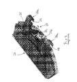
figure 1 is a prospective view of a retaining device according to the invention, where a portion of the support structure has been removed; -
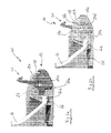
figures 2a and 2b are cross sectional view of the retaining device offigure 1 in an installed configuration on the rim of a glass door of a washing machine; -
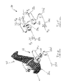
figure 3 is a prospective view of the retaining device offigure 1 , in which the entire support structure has been removed; -
figure 4 is a perspective view of the hook member of the retaining device according tofigures 1 to 3 , with the spring element associated thereto; and -
figure 5 is a perspective view of the spring element offigure 4 . - With reference to the drawings, a retaining
device 10 for the glass door G of a washing machine comprises asupport structure 12 made by twocircular frames 12a and 12b of polymeric material mounted on the rim G1 of the glass door G and kept together for instance by screws (not shown) cooperating with fastening holes 14 (figure 1 ). On one of the circular frames, in the example shown thefront frame 12a which faces the user in the closed configuration of the door G, there are providedseats 16 for anaxle 18 of arotating hook member 20. Similarly, thefront frame 12a presents other seats 22 (cooperating with corresponding seats, not shown, in the back frame 12b) for twoaxles 24 on which two ends 26a of aU-shaped handle 26 are rotatably mounted. Thehook member 20 presents a portion 20a which is inserted in anaperture 27 provided in a side portion 26b of thehandle 26. - Around the
axle 18 of thehook member 20 it is installed a singlesymmetrical spring element 28 made of shaped elastic metal wire which has a central U-shaped portion 28a placed around thehook member 20, second coil portions 28b wound around theaxle 18, thirdU-shaped portions 28c adapted to abut against the back frame 12b as it will be clear in the following description,fourth coil portions 28d and fifthrectilinear end portions 28e abutting thehandle 26. Thanks to the shape and assembly of thespring element 28, such spring has at least two features which function independently of one another when fixed in the assembled position. The first central portion 28a pushes on thedoor hook member 20. The arrows F1 infigures 1 and5 indicate where the back frame 12b would compress thespring element 28, creating a predetermined pre-tension. The back frame 12b also prevents thespring element 28 from moving when thehandle 26 or thehook member 20 is rotated. Thecoil portions 28b and 28d of thespring element 28 reduce the increase of force as thehook member 20 or thehandle 26 is moved from its neutral position. Infigure 5 there are shown also the potential force F2 exerted by thespring element 28 against thehook member 20 and the potential force F3 exerted against thehandle 26. - The retaining device described above substantially operates as follows.
- When the door G is closed, it is brought towards the front wall of the domestic appliance (not shown); in this movement the
hook member 20 cooperates with a door locking device (not shown) and consequently oscillates about theaxle 18 in a counter-clockwise direction when looking atfigure 1 ,2a and 2b , against the action of thespring element 28. In order to open the door G (when the hook member is not blocked by the door locking device), the user pull thehandle 26 so that, thanks to the coupling between the angled portion 20a of thehook member 20 and theaperture 27 provided in a portion 26b of the handle, the hook member is rotated so as to free it from the locking device. The rotational movement of thehandle 26 around itsaxle 24 is carried out against the force F3 exerted by thespring element 28, and when the user leaves thehandle 26, this latter return to its neutral position shown infigures 2a and 2b . - In the closed position, the
hook member 20 may be rotated due to its relative position to the door lock (this varies due to tolerances of the door). Without the spring acting on the handle, the handle would be free to rotate to some extent, but with the spring acting independently on the handle, the handle stays in the neutral position. - The solution of the invention as described above enables the use of a single spring element for driving both the hook member and the handle towards a neutral position and to elastically react against the rotational movement of such components. The device of the invention is particularly suited to use in washing machines, of both the top-loading and front-loading types.
Claims (8)
- A retaining device for a door (G) of a domestic appliance, particularly for a washing machine, comprising a support structure (12) adapted to be secured to the door, a hook member (20) projecting at least partially outside this structure (12) and mounted rotatably around an axis (18) between a locking position and an unlocking position and adapted to cooperate with a door locking device provided in the appliance, a spring element (28) adapted to urge the hook member (20) towards its locking position and a handle (26) mounted rotatably on the support structure (12) and adapted to move the hook member (20) towards its unlocking position, characterized in that the spring element (28) presents at least a first elastic portion (28a, 28b) interposed between the support structure (12) and the hook member (20) and at least a second elastic portion (28d, 28e) interposed between the support structure (12) and the handle (26).
- A retaining device according to claim 1, wherein the spring element comprises a shaped elastic wire (28), the first elastic portion of the spring element (28) having two first symmetrical coil parts (28b) adjacent the hook member (20) and joined together by a U-shaped central portion (28a) abutting the hook member (20).
- A retaining device according to claim 2, wherein the second elastic portion of the spring element (28) comprises two second symmetrical coil parts (28d).
- A retaining device according to claim 2 or 3, wherein the first symmetrical coil parts (28b) are wound around an axle (18) of the hook member (20).
- A retaining device according to claim 2 and 3, wherein between each first coil part (28b) and each second coil part (28d) the spring element (28) presents a U-shaped portion (28c) acting on the support structure (12).
- A retaining device according to any of claim 2-5, wherein the spring element (28) presents substantially rectilinear ends (28e) contacting the handle (26)
- A retaining device according to any of the preceding claims, wherein the spring element (28) is shaped so that the first and second elastic portions are pre-tensioned against the hook member (20) and the handle (26) respectively.
- Domestic appliance, particularly front loading washer, having a door (G) provided with a door retaining device according to any of the preceding claims.
Priority Applications (3)
| Application Number | Priority Date | Filing Date | Title |
|---|---|---|---|
| EP10193986.6A EP2463434B1 (en) | 2010-12-07 | 2010-12-07 | Retaining device for a door of a washing machine |
| PL10193986T PL2463434T3 (en) | 2010-12-07 | 2010-12-07 | Retaining device for a door of a washing machine |
| ES10193986T ES2417005T3 (en) | 2010-12-07 | 2010-12-07 | Retention device for a door of a washing machine |
Applications Claiming Priority (1)
| Application Number | Priority Date | Filing Date | Title |
|---|---|---|---|
| EP10193986.6A EP2463434B1 (en) | 2010-12-07 | 2010-12-07 | Retaining device for a door of a washing machine |
Publications (2)
| Publication Number | Publication Date |
|---|---|
| EP2463434A1 true EP2463434A1 (en) | 2012-06-13 |
| EP2463434B1 EP2463434B1 (en) | 2013-05-29 |
Family
ID=43982371
Family Applications (1)
| Application Number | Title | Priority Date | Filing Date |
|---|---|---|---|
| EP10193986.6A Not-in-force EP2463434B1 (en) | 2010-12-07 | 2010-12-07 | Retaining device for a door of a washing machine |
Country Status (3)
| Country | Link |
|---|---|
| EP (1) | EP2463434B1 (en) |
| ES (1) | ES2417005T3 (en) |
| PL (1) | PL2463434T3 (en) |
Cited By (2)
| Publication number | Priority date | Publication date | Assignee | Title |
|---|---|---|---|---|
| EP2740835A1 (en) * | 2012-12-07 | 2014-06-11 | Dongbu Daewoo Electronics Corporation | Door apparatus for drum type washing machine |
| WO2015185091A1 (en) * | 2014-06-02 | 2015-12-10 | Arcelik Anonim Sirketi | Laundry treatment appliance having an improved front door opening mechanism |
Citations (3)
| Publication number | Priority date | Publication date | Assignee | Title |
|---|---|---|---|---|
| DE3809998C2 (en) * | 1988-03-24 | 1994-04-14 | Bosch Siemens Hausgeraete | Assembly with door handle and catch for a washing machine or the like |
| DE19504796A1 (en) * | 1995-02-14 | 1996-08-22 | Ymos Ag Ind Produkte | Lock on door of washing machine |
| US20040177656A1 (en) * | 2002-11-28 | 2004-09-16 | Kwon Ik Kun | Hook assembly for door in washing machine |
-
2010
- 2010-12-07 EP EP10193986.6A patent/EP2463434B1/en not_active Not-in-force
- 2010-12-07 PL PL10193986T patent/PL2463434T3/en unknown
- 2010-12-07 ES ES10193986T patent/ES2417005T3/en active Active
Patent Citations (3)
| Publication number | Priority date | Publication date | Assignee | Title |
|---|---|---|---|---|
| DE3809998C2 (en) * | 1988-03-24 | 1994-04-14 | Bosch Siemens Hausgeraete | Assembly with door handle and catch for a washing machine or the like |
| DE19504796A1 (en) * | 1995-02-14 | 1996-08-22 | Ymos Ag Ind Produkte | Lock on door of washing machine |
| US20040177656A1 (en) * | 2002-11-28 | 2004-09-16 | Kwon Ik Kun | Hook assembly for door in washing machine |
Cited By (3)
| Publication number | Priority date | Publication date | Assignee | Title |
|---|---|---|---|---|
| EP2740835A1 (en) * | 2012-12-07 | 2014-06-11 | Dongbu Daewoo Electronics Corporation | Door apparatus for drum type washing machine |
| CN103866534A (en) * | 2012-12-07 | 2014-06-18 | 东部大宇电子株式会社 | Door apparatus for drum type washing machine |
| WO2015185091A1 (en) * | 2014-06-02 | 2015-12-10 | Arcelik Anonim Sirketi | Laundry treatment appliance having an improved front door opening mechanism |
Also Published As
| Publication number | Publication date |
|---|---|
| EP2463434B1 (en) | 2013-05-29 |
| PL2463434T3 (en) | 2013-08-30 |
| ES2417005T3 (en) | 2013-08-05 |
Similar Documents
| Publication | Publication Date | Title |
|---|---|---|
| KR101264953B1 (en) | Vehicle grab handle | |
| WO2012084483A1 (en) | A washer/dryer comprising a lock | |
| EP2909405B1 (en) | Door-lock device | |
| EP2463434B1 (en) | Retaining device for a door of a washing machine | |
| US20080178634A1 (en) | Laundry machine | |
| KR20110013137A (en) | Washing machine | |
| EP3265634A1 (en) | Domestic appliance and hinge of a domestic appliance | |
| EP1418266A2 (en) | A device for locking the closure door of a washing machine | |
| EP3066279B1 (en) | Appliance latch striker | |
| DE102012101536B3 (en) | Domestic appliance e.g. dishwasher, has holding device that is out-hinged supported from outer surface of diaphragm or housing wall for holding or fixing mobile device to diaphragm or housing in effective range of data transfer | |
| EP2204486A2 (en) | Electrical home appliance with top cover | |
| US9523220B2 (en) | Door outside handle for vehicle | |
| EP2981644B1 (en) | A washer/dryer comprising a lock | |
| WO2007110441A1 (en) | A household appliance | |
| EP2981202B1 (en) | A household appliance comprising a lock | |
| WO2007110442A1 (en) | A locking mechanism for a household appliance | |
| EP1990459A1 (en) | Elastic opposition device for a door of a front-loading dishwashing machine, and dishwashing machine including such a device | |
| CN111194367B (en) | Laundry care appliance with a holding device | |
| CN114941478B (en) | Door locks for household appliances and household appliances including such door locks. | |
| KR102257624B1 (en) | Laundry treating apparatus | |
| US9290972B2 (en) | Latch assembly | |
| EP2458057A1 (en) | Appliance handle assembly and method for mounting such assembly to an appliance | |
| US1207486A (en) | Clothes-pin. | |
| DE102016214825A1 (en) | Domestic appliance with automatic door opening device and method for its operation | |
| CN108291351A (en) | It include the household appliance for handling clothing that fixed imbalance compensation device is pressed from both sides by radial elastic |
Legal Events
| Date | Code | Title | Description |
|---|---|---|---|
| PUAI | Public reference made under article 153(3) epc to a published international application that has entered the european phase |
Free format text: ORIGINAL CODE: 0009012 |
|
| AK | Designated contracting states |
Kind code of ref document: A1 Designated state(s): AL AT BE BG CH CY CZ DE DK EE ES FI FR GB GR HR HU IE IS IT LI LT LU LV MC MK MT NL NO PL PT RO RS SE SI SK SM TR |
|
| AX | Request for extension of the european patent |
Extension state: BA ME |
|
| 17P | Request for examination filed |
Effective date: 20121130 |
|
| GRAP | Despatch of communication of intention to grant a patent |
Free format text: ORIGINAL CODE: EPIDOSNIGR1 |
|
| RIC1 | Information provided on ipc code assigned before grant |
Ipc: A47L 15/42 20060101ALI20130131BHEP Ipc: D06F 39/14 20060101ALI20130131BHEP Ipc: D06F 37/28 20060101AFI20130131BHEP |
|
| GRAS | Grant fee paid |
Free format text: ORIGINAL CODE: EPIDOSNIGR3 |
|
| GRAA | (expected) grant |
Free format text: ORIGINAL CODE: 0009210 |
|
| AK | Designated contracting states |
Kind code of ref document: B1 Designated state(s): AL AT BE BG CH CY CZ DE DK EE ES FI FR GB GR HR HU IE IS IT LI LT LU LV MC MK MT NL NO PL PT RO RS SE SI SK SM TR |
|
| REG | Reference to a national code |
Ref country code: GB Ref legal event code: FG4D |
|
| REG | Reference to a national code |
Ref country code: CH Ref legal event code: EP |
|
| REG | Reference to a national code |
Ref country code: AT Ref legal event code: REF Ref document number: 614479 Country of ref document: AT Kind code of ref document: T Effective date: 20130615 |
|
| REG | Reference to a national code |
Ref country code: IE Ref legal event code: FG4D |
|
| REG | Reference to a national code |
Ref country code: DE Ref legal event code: R096 Ref document number: 602010007280 Country of ref document: DE Effective date: 20130725 |
|
| REG | Reference to a national code |
Ref country code: ES Ref legal event code: FG2A Ref document number: 2417005 Country of ref document: ES Kind code of ref document: T3 Effective date: 20130805 |
|
| REG | Reference to a national code |
Ref country code: PL Ref legal event code: T3 |
|
| REG | Reference to a national code |
Ref country code: AT Ref legal event code: MK05 Ref document number: 614479 Country of ref document: AT Kind code of ref document: T Effective date: 20130529 |
|
| REG | Reference to a national code |
Ref country code: LT Ref legal event code: MG4D |
|
| PG25 | Lapsed in a contracting state [announced via postgrant information from national office to epo] |
Ref country code: IS Free format text: LAPSE BECAUSE OF FAILURE TO SUBMIT A TRANSLATION OF THE DESCRIPTION OR TO PAY THE FEE WITHIN THE PRESCRIBED TIME-LIMIT Effective date: 20130929 Ref country code: FI Free format text: LAPSE BECAUSE OF FAILURE TO SUBMIT A TRANSLATION OF THE DESCRIPTION OR TO PAY THE FEE WITHIN THE PRESCRIBED TIME-LIMIT Effective date: 20130529 Ref country code: PT Free format text: LAPSE BECAUSE OF FAILURE TO SUBMIT A TRANSLATION OF THE DESCRIPTION OR TO PAY THE FEE WITHIN THE PRESCRIBED TIME-LIMIT Effective date: 20130930 Ref country code: SI Free format text: LAPSE BECAUSE OF FAILURE TO SUBMIT A TRANSLATION OF THE DESCRIPTION OR TO PAY THE FEE WITHIN THE PRESCRIBED TIME-LIMIT Effective date: 20130529 Ref country code: AT Free format text: LAPSE BECAUSE OF FAILURE TO SUBMIT A TRANSLATION OF THE DESCRIPTION OR TO PAY THE FEE WITHIN THE PRESCRIBED TIME-LIMIT Effective date: 20130529 Ref country code: NO Free format text: LAPSE BECAUSE OF FAILURE TO SUBMIT A TRANSLATION OF THE DESCRIPTION OR TO PAY THE FEE WITHIN THE PRESCRIBED TIME-LIMIT Effective date: 20130829 Ref country code: GR Free format text: LAPSE BECAUSE OF FAILURE TO SUBMIT A TRANSLATION OF THE DESCRIPTION OR TO PAY THE FEE WITHIN THE PRESCRIBED TIME-LIMIT Effective date: 20130830 Ref country code: SE Free format text: LAPSE BECAUSE OF FAILURE TO SUBMIT A TRANSLATION OF THE DESCRIPTION OR TO PAY THE FEE WITHIN THE PRESCRIBED TIME-LIMIT Effective date: 20130529 Ref country code: LT Free format text: LAPSE BECAUSE OF FAILURE TO SUBMIT A TRANSLATION OF THE DESCRIPTION OR TO PAY THE FEE WITHIN THE PRESCRIBED TIME-LIMIT Effective date: 20130529 |
|
| REG | Reference to a national code |
Ref country code: NL Ref legal event code: VDEP Effective date: 20130529 |
|
| PG25 | Lapsed in a contracting state [announced via postgrant information from national office to epo] |
Ref country code: BG Free format text: LAPSE BECAUSE OF FAILURE TO SUBMIT A TRANSLATION OF THE DESCRIPTION OR TO PAY THE FEE WITHIN THE PRESCRIBED TIME-LIMIT Effective date: 20130829 Ref country code: HR Free format text: LAPSE BECAUSE OF FAILURE TO SUBMIT A TRANSLATION OF THE DESCRIPTION OR TO PAY THE FEE WITHIN THE PRESCRIBED TIME-LIMIT Effective date: 20130529 Ref country code: RS Free format text: LAPSE BECAUSE OF FAILURE TO SUBMIT A TRANSLATION OF THE DESCRIPTION OR TO PAY THE FEE WITHIN THE PRESCRIBED TIME-LIMIT Effective date: 20130529 |
|
| PG25 | Lapsed in a contracting state [announced via postgrant information from national office to epo] |
Ref country code: LV Free format text: LAPSE BECAUSE OF FAILURE TO SUBMIT A TRANSLATION OF THE DESCRIPTION OR TO PAY THE FEE WITHIN THE PRESCRIBED TIME-LIMIT Effective date: 20130529 |
|
| PG25 | Lapsed in a contracting state [announced via postgrant information from national office to epo] |
Ref country code: DK Free format text: LAPSE BECAUSE OF FAILURE TO SUBMIT A TRANSLATION OF THE DESCRIPTION OR TO PAY THE FEE WITHIN THE PRESCRIBED TIME-LIMIT Effective date: 20130529 Ref country code: CZ Free format text: LAPSE BECAUSE OF FAILURE TO SUBMIT A TRANSLATION OF THE DESCRIPTION OR TO PAY THE FEE WITHIN THE PRESCRIBED TIME-LIMIT Effective date: 20130529 Ref country code: EE Free format text: LAPSE BECAUSE OF FAILURE TO SUBMIT A TRANSLATION OF THE DESCRIPTION OR TO PAY THE FEE WITHIN THE PRESCRIBED TIME-LIMIT Effective date: 20130529 Ref country code: BE Free format text: LAPSE BECAUSE OF FAILURE TO SUBMIT A TRANSLATION OF THE DESCRIPTION OR TO PAY THE FEE WITHIN THE PRESCRIBED TIME-LIMIT Effective date: 20130529 Ref country code: SK Free format text: LAPSE BECAUSE OF FAILURE TO SUBMIT A TRANSLATION OF THE DESCRIPTION OR TO PAY THE FEE WITHIN THE PRESCRIBED TIME-LIMIT Effective date: 20130529 |
|
| PG25 | Lapsed in a contracting state [announced via postgrant information from national office to epo] |
Ref country code: NL Free format text: LAPSE BECAUSE OF FAILURE TO SUBMIT A TRANSLATION OF THE DESCRIPTION OR TO PAY THE FEE WITHIN THE PRESCRIBED TIME-LIMIT Effective date: 20130529 Ref country code: RO Free format text: LAPSE BECAUSE OF FAILURE TO SUBMIT A TRANSLATION OF THE DESCRIPTION OR TO PAY THE FEE WITHIN THE PRESCRIBED TIME-LIMIT Effective date: 20130529 |
|
| PLBE | No opposition filed within time limit |
Free format text: ORIGINAL CODE: 0009261 |
|
| STAA | Information on the status of an ep patent application or granted ep patent |
Free format text: STATUS: NO OPPOSITION FILED WITHIN TIME LIMIT |
|
| 26N | No opposition filed |
Effective date: 20140303 |
|
| REG | Reference to a national code |
Ref country code: DE Ref legal event code: R097 Ref document number: 602010007280 Country of ref document: DE Effective date: 20140303 |
|
| PG25 | Lapsed in a contracting state [announced via postgrant information from national office to epo] |
Ref country code: MC Free format text: LAPSE BECAUSE OF FAILURE TO SUBMIT A TRANSLATION OF THE DESCRIPTION OR TO PAY THE FEE WITHIN THE PRESCRIBED TIME-LIMIT Effective date: 20130529 |
|
| PG25 | Lapsed in a contracting state [announced via postgrant information from national office to epo] |
Ref country code: LU Free format text: LAPSE BECAUSE OF FAILURE TO SUBMIT A TRANSLATION OF THE DESCRIPTION OR TO PAY THE FEE WITHIN THE PRESCRIBED TIME-LIMIT Effective date: 20131207 |
|
| REG | Reference to a national code |
Ref country code: IE Ref legal event code: MM4A |
|
| PG25 | Lapsed in a contracting state [announced via postgrant information from national office to epo] |
Ref country code: IE Free format text: LAPSE BECAUSE OF NON-PAYMENT OF DUE FEES Effective date: 20131207 |
|
| PG25 | Lapsed in a contracting state [announced via postgrant information from national office to epo] |
Ref country code: SM Free format text: LAPSE BECAUSE OF FAILURE TO SUBMIT A TRANSLATION OF THE DESCRIPTION OR TO PAY THE FEE WITHIN THE PRESCRIBED TIME-LIMIT Effective date: 20130529 |
|
| PG25 | Lapsed in a contracting state [announced via postgrant information from national office to epo] |
Ref country code: CY Free format text: LAPSE BECAUSE OF FAILURE TO SUBMIT A TRANSLATION OF THE DESCRIPTION OR TO PAY THE FEE WITHIN THE PRESCRIBED TIME-LIMIT Effective date: 20130529 Ref country code: TR Free format text: LAPSE BECAUSE OF FAILURE TO SUBMIT A TRANSLATION OF THE DESCRIPTION OR TO PAY THE FEE WITHIN THE PRESCRIBED TIME-LIMIT Effective date: 20130529 |
|
| PG25 | Lapsed in a contracting state [announced via postgrant information from national office to epo] |
Ref country code: MK Free format text: LAPSE BECAUSE OF FAILURE TO SUBMIT A TRANSLATION OF THE DESCRIPTION OR TO PAY THE FEE WITHIN THE PRESCRIBED TIME-LIMIT Effective date: 20130529 Ref country code: HU Free format text: LAPSE BECAUSE OF FAILURE TO SUBMIT A TRANSLATION OF THE DESCRIPTION OR TO PAY THE FEE WITHIN THE PRESCRIBED TIME-LIMIT; INVALID AB INITIO Effective date: 20101207 |
|
| REG | Reference to a national code |
Ref country code: CH Ref legal event code: PL |
|
| PG25 | Lapsed in a contracting state [announced via postgrant information from national office to epo] |
Ref country code: MT Free format text: LAPSE BECAUSE OF FAILURE TO SUBMIT A TRANSLATION OF THE DESCRIPTION OR TO PAY THE FEE WITHIN THE PRESCRIBED TIME-LIMIT Effective date: 20130529 |
|
| PG25 | Lapsed in a contracting state [announced via postgrant information from national office to epo] |
Ref country code: CH Free format text: LAPSE BECAUSE OF NON-PAYMENT OF DUE FEES Effective date: 20141231 Ref country code: LI Free format text: LAPSE BECAUSE OF NON-PAYMENT OF DUE FEES Effective date: 20141231 |
|
| REG | Reference to a national code |
Ref country code: FR Ref legal event code: PLFP Year of fee payment: 6 |
|
| REG | Reference to a national code |
Ref country code: FR Ref legal event code: PLFP Year of fee payment: 7 |
|
| PGFP | Annual fee paid to national office [announced via postgrant information from national office to epo] |
Ref country code: ES Payment date: 20161111 Year of fee payment: 7 |
|
| REG | Reference to a national code |
Ref country code: FR Ref legal event code: PLFP Year of fee payment: 8 |
|
| PGFP | Annual fee paid to national office [announced via postgrant information from national office to epo] |
Ref country code: PL Payment date: 20170915 Year of fee payment: 8 |
|
| PGFP | Annual fee paid to national office [announced via postgrant information from national office to epo] |
Ref country code: FR Payment date: 20171113 Year of fee payment: 8 Ref country code: DE Payment date: 20171129 Year of fee payment: 8 |
|
| PGFP | Annual fee paid to national office [announced via postgrant information from national office to epo] |
Ref country code: GB Payment date: 20171206 Year of fee payment: 8 |
|
| PGFP | Annual fee paid to national office [announced via postgrant information from national office to epo] |
Ref country code: IT Payment date: 20171221 Year of fee payment: 8 |
|
| PG25 | Lapsed in a contracting state [announced via postgrant information from national office to epo] |
Ref country code: AL Free format text: LAPSE BECAUSE OF FAILURE TO SUBMIT A TRANSLATION OF THE DESCRIPTION OR TO PAY THE FEE WITHIN THE PRESCRIBED TIME-LIMIT Effective date: 20130529 |
|
| REG | Reference to a national code |
Ref country code: ES Ref legal event code: FD2A Effective date: 20190702 Ref country code: DE Ref legal event code: R119 Ref document number: 602010007280 Country of ref document: DE |
|
| PG25 | Lapsed in a contracting state [announced via postgrant information from national office to epo] |
Ref country code: ES Free format text: LAPSE BECAUSE OF NON-PAYMENT OF DUE FEES Effective date: 20171208 |
|
| GBPC | Gb: european patent ceased through non-payment of renewal fee |
Effective date: 20181207 |
|
| PG25 | Lapsed in a contracting state [announced via postgrant information from national office to epo] |
Ref country code: DE Free format text: LAPSE BECAUSE OF NON-PAYMENT OF DUE FEES Effective date: 20190702 Ref country code: IT Free format text: LAPSE BECAUSE OF NON-PAYMENT OF DUE FEES Effective date: 20181207 Ref country code: FR Free format text: LAPSE BECAUSE OF NON-PAYMENT OF DUE FEES Effective date: 20181231 |
|
| PG25 | Lapsed in a contracting state [announced via postgrant information from national office to epo] |
Ref country code: GB Free format text: LAPSE BECAUSE OF NON-PAYMENT OF DUE FEES Effective date: 20181207 |
|
| PG25 | Lapsed in a contracting state [announced via postgrant information from national office to epo] |
Ref country code: PL Free format text: LAPSE BECAUSE OF NON-PAYMENT OF DUE FEES Effective date: 20181207 |