EP2463176A1 - Shaft-and-yoke coupling structure and vehicle steering system - Google Patents
Shaft-and-yoke coupling structure and vehicle steering system Download PDFInfo
- Publication number
- EP2463176A1 EP2463176A1 EP11192095A EP11192095A EP2463176A1 EP 2463176 A1 EP2463176 A1 EP 2463176A1 EP 11192095 A EP11192095 A EP 11192095A EP 11192095 A EP11192095 A EP 11192095A EP 2463176 A1 EP2463176 A1 EP 2463176A1
- Authority
- EP
- European Patent Office
- Prior art keywords
- shaft
- steering
- yoke
- coupling structure
- transmission shaft
- Prior art date
- Legal status (The legal status is an assumption and is not a legal conclusion. Google has not performed a legal analysis and makes no representation as to the accuracy of the status listed.)
- Granted
Links
Images


Classifications
-
- B—PERFORMING OPERATIONS; TRANSPORTING
- B62—LAND VEHICLES FOR TRAVELLING OTHERWISE THAN ON RAILS
- B62D—MOTOR VEHICLES; TRAILERS
- B62D1/00—Steering controls, i.e. means for initiating a change of direction of the vehicle
- B62D1/02—Steering controls, i.e. means for initiating a change of direction of the vehicle vehicle-mounted
- B62D1/16—Steering columns
-
- B—PERFORMING OPERATIONS; TRANSPORTING
- B62—LAND VEHICLES FOR TRAVELLING OTHERWISE THAN ON RAILS
- B62D—MOTOR VEHICLES; TRAILERS
- B62D1/00—Steering controls, i.e. means for initiating a change of direction of the vehicle
- B62D1/02—Steering controls, i.e. means for initiating a change of direction of the vehicle vehicle-mounted
- B62D1/16—Steering columns
- B62D1/20—Connecting steering column to steering gear
-
- F—MECHANICAL ENGINEERING; LIGHTING; HEATING; WEAPONS; BLASTING
- F16—ENGINEERING ELEMENTS AND UNITS; GENERAL MEASURES FOR PRODUCING AND MAINTAINING EFFECTIVE FUNCTIONING OF MACHINES OR INSTALLATIONS; THERMAL INSULATION IN GENERAL
- F16D—COUPLINGS FOR TRANSMITTING ROTATION; CLUTCHES; BRAKES
- F16D1/00—Couplings for rigidly connecting two coaxial shafts or other movable machine elements
- F16D1/06—Couplings for rigidly connecting two coaxial shafts or other movable machine elements for attachment of a member on a shaft or on a shaft-end
- F16D1/064—Couplings for rigidly connecting two coaxial shafts or other movable machine elements for attachment of a member on a shaft or on a shaft-end non-disconnectable
- F16D1/068—Couplings for rigidly connecting two coaxial shafts or other movable machine elements for attachment of a member on a shaft or on a shaft-end non-disconnectable involving gluing, welding or the like
-
- F—MECHANICAL ENGINEERING; LIGHTING; HEATING; WEAPONS; BLASTING
- F16—ENGINEERING ELEMENTS AND UNITS; GENERAL MEASURES FOR PRODUCING AND MAINTAINING EFFECTIVE FUNCTIONING OF MACHINES OR INSTALLATIONS; THERMAL INSULATION IN GENERAL
- F16D—COUPLINGS FOR TRANSMITTING ROTATION; CLUTCHES; BRAKES
- F16D3/00—Yielding couplings, i.e. with means permitting movement between the connected parts during the drive
- F16D3/16—Universal joints in which flexibility is produced by means of pivots or sliding or rolling connecting parts
- F16D3/26—Hooke's joints or other joints with an equivalent intermediate member to which each coupling part is pivotally or slidably connected
- F16D3/38—Hooke's joints or other joints with an equivalent intermediate member to which each coupling part is pivotally or slidably connected with a single intermediate member with trunnions or bearings arranged on two axes perpendicular to one another
- F16D3/382—Hooke's joints or other joints with an equivalent intermediate member to which each coupling part is pivotally or slidably connected with a single intermediate member with trunnions or bearings arranged on two axes perpendicular to one another constructional details of other than the intermediate member
- F16D3/387—Fork construction; Mounting of fork on shaft; Adapting shaft for mounting of fork
-
- Y—GENERAL TAGGING OF NEW TECHNOLOGICAL DEVELOPMENTS; GENERAL TAGGING OF CROSS-SECTIONAL TECHNOLOGIES SPANNING OVER SEVERAL SECTIONS OF THE IPC; TECHNICAL SUBJECTS COVERED BY FORMER USPC CROSS-REFERENCE ART COLLECTIONS [XRACs] AND DIGESTS
- Y10—TECHNICAL SUBJECTS COVERED BY FORMER USPC
- Y10T—TECHNICAL SUBJECTS COVERED BY FORMER US CLASSIFICATION
- Y10T403/00—Joints and connections
- Y10T403/70—Interfitted members
- Y10T403/7026—Longitudinally splined or fluted rod
Definitions
- the present invention relates to a shaft-and-yoke coupling structure and a vehicle steering system including the same.
- a steering shaft joined to a steering wheel (steering member) and a steering gear shaft provided as, for example, a pinion shaft are joined to each other via a so-called intermediate shaft being a steering transmission shaft.
- Such an intermediate shaft commonly adopts a telescopic shaft in which an inner shaft and a cylindrical outer shaft are joined to each other in an axially and relatively slidable manner. End portions of the inner and outer shafts of the intermediate shaft are joined, respectively, to the corresponding steering shaft and pinion shaft via a universal joint.
- Yokes of such universal joints have conventionally been fixed integrally by welding, respectively, to inner and outer shafts of an intermediate shaft (refer to, for example, paragraph [0011] in Japanese Published Unexamined Utility Model Application No. Hei 5-46649 ).
- the yokes and the corresponding shafts are fitted in a serrated manner so as to be steerable even in the case of breakage of the welded portions.
- the shafts are swaged to the corresponding yokes in some cases.
- an aspect of the present invention provides a shaft-and-yoke coupling structure including: a steering transmission shaft having an end portion, and a yoke of an universal joint joined to the end portion of the steering transmission shaft, in which the end portion of the steering transmission shaft has a stepped portion and an insertion convex portion protruding from the stepped portion in the axial direction of the steering transmission shaft, the yoke has an annular receiving portion facing and fixed to the stepped portion via a welded portion and an insertion recess portion surrounded by the receiving portion in which the insertion convex portion is inserted, and in which the insertion convex portion and the insertion recess portion are arranged to be engaged with each other with a predetermined amount of play in the direction of rotation when the welded portion is broken.
- the insertion convex portion and the insertion recess portion are engaged with each other with a predetermined amount of play in the direction of rotation.
- the driver can therefore steer the vehicle with a rattling feeling on the steering and can drive to, for example, a repair garage.
- the rattling feeling on the steering can be provided to the driver, allowing the occurrence of an abnormality to be reliably recognized by the driver.
- Fig. 1 shows a general configuration of a vehicle steering system 1 to which a shaft-and-yoke coupling structure P according to an embodiment of the present invention is applied.
- the vehicle steering system 1 includes a steering shaft 3 joined to a steering member 2 such as a steering wheel, a steering intermediate shaft (hereinafter referred to simply as intermediate shaft) 5 being the steering transmission shaft joined to the steering shaft 3 via a first universal joint 4, a pinion shaft 7 joined to the intermediate shaft 5 via a second universal joint 6, and a rack shaft 8 being a steered shaft having a rack 8a to be meshed with a pinion 7a provided in the vicinity of an end portion of the pinion shaft 7.
- a steering intermediate shaft hereinafter referred to simply as intermediate shaft 5
- a pinion shaft 7 joined to the intermediate shaft 5 via a second universal joint 6
- rack shaft 8 being a steered shaft having a rack 8a to be meshed with a pinion 7a provided in the vicinity of an end portion of the pinion shaft 7.
- a rack-and-pinion mechanism including the pinion shaft 7 and the rack shaft 8 constitutes a steered mechanism A1.
- the rack shaft 8 is supported by a housing 10 fixed to a vehicle body-side member 9 in an axially movable manner along a right-left direction of the vehicle (i.e. in the direction perpendicular to the plane of the paper).
- the end portions of the rack shaft 8, although not shown, are joined, respectively, to steered wheels via a tie rod and a knuckle arm.
- the second steering shaft 12 has an input shaft 15 joined to the lower shaft 14 in an associated-rotatable manner, an output shaft 16 joined, via the first universal joint 4, to a first end portion 5a of the intermediate shaft 5 in a torque transmittable manner, and a torsion bar 17 joining the input shaft 15 and the output shaft 16 in a relatively rotatable manner.
- a second end portion 5b of the intermediate shaft 5 is joined, via the second universal joint 6, to the pinion shaft 7 in a torque transmittable manner.
- the steering shaft 3 is supported rotatably, via a bearing not shown, by a steering column 20 fixed to vehicle body-side members 18 and 19.
- the steering column 20 includes a cylindrical upper jacket 21 and a cylindrical lower jacket 22 fitted to each other in an axially and relatively movable manner, and a housing 23 joined to an axial lower end of the lower jacket 22.
- a reduction gear mechanism 25 for reducing and transmitting the power of a steering assist electric motor 24 to the output shaft 16.
- the reduction gear mechanism 25 has a drive gear 26 joined to the rotary shaft (not shown) of the electric motor 24 in an associated-rotatable manner and a driven gear 27 meshed with the drive gear 26 to rotate in a manner associated with the output shaft 16.
- the drive gear 26 is constituted by, for example, a worm shaft
- the driven gear 27 is constituted by, for example, a worm wheel.
- the steering column 20 is fixed to the vehicle body-side members 18 and 19, respectively, via an upper bracket 28 on the rear side of the vehicle and a lower bracket 29 on the front side of the vehicle.
- the upper bracket 28 is also fixable to the upper jacket 21 of the steering column 20 via a column bracket to be described later.
- the upper bracket 28 is fixed to the vehicle body-side member 18 using a fixing bolt (stud bolt) 30 protruding downward from the vehicle body-side member 18, a nut 31 into which the fixing bolt 30 is screwed, and a capsule 32 detachably held on the upper bracket 28.
- the lower bracket 29 is fixed to the housing 23 of the steering column 20.
- the lower bracket 29 is also fixed to the vehicle body-side member 19 using a fixing bolt (stud bolt) 33 protruding from the vehicle body-side member 19 and a nut 34 into which the fixing bolt 33 is screwed.
- the intermediate shaft 5 includes a lower shaft 35 constituted by, for example, an inner shaft and a cylindrical upper shaft 36 constituted by, for example, an outer shaft and fitted on the lower shaft 35 in an axially and relatively slidable manner as well as in an associated-rotatable manner.
- the present embodiment will be described based on an example in which the coupling structure P between a steering transmission shaft and a yoke of a universal joint is applied to a coupling structure between the first end portion 5a of the intermediate shaft 5 anda first yoke 41 of the first universal joint 4, but not limited thereto.
- the coupling structure P may be applied to a coupling structure between the second end portion 5b of the intermediate shaft 5 and a yoke of the second universal joint 6.
- the first universal joint 4 includes the first yoke 41 to which an end portion of the upper shaft 36 being the first end portion 5a of the intermediate shaft 5 is joined, a second yoke 42 to which an end portion 16a of the output shaft 16 of the second steering shaft 12 is joined, and a joint cross 43 joining the first yoke 41 and the second yoke 42 to each other.
- Female serrations 38 formed on an inner periphery of the cylindrical upper shaft 36 are fitted on male serrations 37 formed on an outer periphery of the lower shaft 35 of the intermediate shaft 5.
- the first end portion 5a of the intermediate shaft 5 has a stepped portion 51 and an insertion convex portion 52 protruding from the stepped portion 51 in the axial direction X1.
- the first yoke 41 of the first universal joint 4 has an annular receiving portion 53 facing and fixed to the stepped portion 51 via a welded portion 55 and an insertion recess portion 54 surrounded by the receiving portion 53 in which the insertion convex portion 52 is inserted.
- the welded portion 55 between the stepped portion 51 and the receiving portion 53 may be arranged on an entire periphery of the stepped portion 51 or at multiple portions in the circumferential direction C1.
- the present embodiment is characterized in that the insertion convex portion 52 and the insertion recess portion 54 are engageable with each other with a predetermined amount of play in the direction of rotation in the case of breakage of the welded portion 55. This can lead to a fail-safe function for steerability and, at the same time, provide a rattling feeling on the steering allowing the occurrence of an abnormality to be reliably recognized by the driver.
- an outer periphery 52a of the insertion convex portion 52 has a plurality of joint convex portions 56 protruding outward in the radial direction R1.
- the plurality of joint convex portions 56 are arranged at regular intervals in the circumferential direction C1.
- an inner periphery 54a of the insertion recess portion 54 has a plurality of joint recess portions 57 recessed outward in the radial direction R1. At least the leading end portions of the joint convex portions 56 are housed, respectively, in the corresponding joint recess portions 57 with a predetermined amount of clearance S1 and S2 in the direction of rotation (corresponding to the circumferential direction C1).
- the joint convex portions 56 are engageable, respectively, with the corresponding joint recess portions 57 with a play Q1 (corresponding to a predetermined angle set within a range from 10 to 30 degrees, for example) in the direction of rotation (circumferential direction C1).
- the insertion convex portion 52 of the intermediate shaft 5 and the insertion recess portion 54 of the first yoke 41 are engaged with each other with a predetermined amount of play Q1 in the direction of rotation (circumferential direction C1).
- the driver can therefore steer the vehicle with a rattling feeling on the steering and can drive to, for example, a repair garage.
- the rattling feeling on the steering can be provided to the driver, allowing the occurrence of an abnormality to be reliably recognized by the driver.
- the joint convex portions 56 on the outer periphery 52a of the insertion convex portion 52 are engaged with the inner periphery 54a of the insertion recess portion 54 with a predetermined amount of play Q1 in the direction of rotation to be steerable and, at the same time, provide a rattling feeling on the steering to the driver to thereby warn of the occurrence of an abnormality and encourage the driver to repair the vehicle.
- the steering transmission shaft being the intermediate shaft 5 as in the present embodiment has the advantage that the first end portion 5a of the intermediate shaft 5 is joined to the output shaft 16 of the second steering shaft 12 via the Cardin-type first universal joint 4, while the second end portion 5b of the intermediate shaft 5 is joined to the pinion shaft 7 being a steering gear shaft via the Cardin-type second universal joint 6.
- joint convex portions 56 are arranged at regular intervals in the embodiment shown in Figs. 4A and 4B , two joint convex portions may be arranged at 180-degree intervals or three joint convex portions may be arranged at 120-degree intervals or the number of joint recess portions provided may be the same as that of the joint convex portions. Five or more joint convex portions and the same number of the joint recess portions may be provided.
- the joint convex portions and the joint recess portions may be formed in any shape without limiting to such a chevron shape as shown in Figs. 4A and 4B .
Landscapes
- Engineering & Computer Science (AREA)
- General Engineering & Computer Science (AREA)
- Mechanical Engineering (AREA)
- Chemical & Material Sciences (AREA)
- Combustion & Propulsion (AREA)
- Transportation (AREA)
- Steering Controls (AREA)
- Power Steering Mechanism (AREA)
Abstract
Description
- The present invention relates to a shaft-and-yoke coupling structure and a vehicle steering system including the same.
- Generally, in motor vehicles, a steering shaft joined to a steering wheel (steering member) and a steering gear shaft provided as, for example, a pinion shaft are joined to each other via a so-called intermediate shaft being a steering transmission shaft.
- Such an intermediate shaft commonly adopts a telescopic shaft in which an inner shaft and a cylindrical outer shaft are joined to each other in an axially and relatively slidable manner. End portions of the inner and outer shafts of the intermediate shaft are joined, respectively, to the corresponding steering shaft and pinion shaft via a universal joint.
- Yokes of such universal joints have conventionally been fixed integrally by welding, respectively, to inner and outer shafts of an intermediate shaft (refer to, for example, paragraph [0011] in Japanese Published Unexamined Utility Model Application No.
Hei 5-46649 - Thus adding a serrated fitting and/or swaging allows a torque to be transmitted between the yokes of the universal joints and the intermediate shaft, even in the case of breakage of the welded portions, and thereby a fail-safe function to be achieved.
- However, since the torque transmission between the yokes of the universal joints and the intermediate shaft is maintained sufficiently even in the case of breakage of the welded portions, the driver cannot recognize the occurrence of an abnormality. This may cause the driver to continue driving for a long period of time with no repair.
- It is therefore an object of the present invention to provide a shaft-and-yoke coupling structure and a vehicle steering system including the same that can perform a fail-safe function in the case of breakage of a welded portion as well as allowing the occurrence of an abnormality to be recognized by the driver.
- In order to achieve the foregoing object, an aspect of the present invention provides a shaft-and-yoke coupling structure including: a steering transmission shaft having an end portion, and a yoke of an universal joint joined to the end portion of the steering transmission shaft, in which the end portion of the steering transmission shaft has a stepped portion and an insertion convex portion protruding from the stepped portion in the axial direction of the steering transmission shaft, the yoke has an annular receiving portion facing and fixed to the stepped portion via a welded portion and an insertion recess portion surrounded by the receiving portion in which the insertion convex portion is inserted, and in which the insertion convex portion and the insertion recess portion are arranged to be engaged with each other with a predetermined amount of play in the direction of rotation when the welded portion is broken.
- According to the aspect of the present invention, even in the case of breakage of the welded portion, the insertion convex portion and the insertion recess portion are engaged with each other with a predetermined amount of play in the direction of rotation. The driver can therefore steer the vehicle with a rattling feeling on the steering and can drive to, for example, a repair garage. The rattling feeling on the steering can be provided to the driver, allowing the occurrence of an abnormality to be reliably recognized by the driver.
-
-
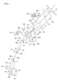
Fig. 1 is a schematic view showing a general configuration of a vehicle steering system to which a shaft-and-yoke coupling structure according to an embodiment of the present invention is applied. A steering transmission shaft and a yoke are coupled through the coupling structure. -
Fig. 2 is a schematic side view of the coupling structure between a steering intermediate shaft being the steering transmission shaft and the yoke of the universal joint. -
Fig. 3 is an enlarged view of an essential portion of the coupling structure shown inFig. 2 . -
Fig. 4A is a sectional view taken along the line IVa-IVa inFig. 3 , showing the coupling structure in a normal state, whileFig. 4B shows the coupling structure on occurrence of an abnormality. - Preferred embodiments of the present invention will be described with reference to the accompanying drawings.
-
Fig. 1 shows a general configuration of a vehicle steering system 1 to which a shaft-and-yoke coupling structure P according to an embodiment of the present invention is applied. Referring toFig. 1 , the vehicle steering system 1 includes asteering shaft 3 joined to asteering member 2 such as a steering wheel, a steering intermediate shaft (hereinafter referred to simply as intermediate shaft) 5 being the steering transmission shaft joined to thesteering shaft 3 via a firstuniversal joint 4, apinion shaft 7 joined to theintermediate shaft 5 via a seconduniversal joint 6, and a rack shaft 8 being a steered shaft having arack 8a to be meshed with apinion 7a provided in the vicinity of an end portion of thepinion shaft 7. - A rack-and-pinion mechanism including the
pinion shaft 7 and the rack shaft 8 constitutes a steered mechanism A1. The rack shaft 8 is supported by ahousing 10 fixed to a vehicle body-side member 9 in an axially movable manner along a right-left direction of the vehicle (i.e. in the direction perpendicular to the plane of the paper). The end portions of the rack shaft 8, although not shown, are joined, respectively, to steered wheels via a tie rod and a knuckle arm. - The
steering shaft 3 includes afirst steering shaft 11 and asecond steering shaft 12 joined coaxially to each other. Thefirst steering shaft 11 has anupper shaft 13 and alower shaft 14 fitted, using spline coupling, to each other in an associated-rotatable manner as well as in an axially and relatively slidable manner. One of theupper shaft 13 and thelower shaft 14 constitutes an inner shaft, while the other constitutes a cylindrical outer shaft (hollow shaft). - The
second steering shaft 12 has aninput shaft 15 joined to thelower shaft 14 in an associated-rotatable manner, anoutput shaft 16 joined, via the firstuniversal joint 4, to afirst end portion 5a of theintermediate shaft 5 in a torque transmittable manner, and atorsion bar 17 joining theinput shaft 15 and theoutput shaft 16 in a relatively rotatable manner. On the other hand, asecond end portion 5b of theintermediate shaft 5 is joined, via the seconduniversal joint 6, to thepinion shaft 7 in a torque transmittable manner. - The
steering shaft 3 is supported rotatably, via a bearing not shown, by asteering column 20 fixed to vehicle body-side members - The
steering column 20 includes a cylindricalupper jacket 21 and a cylindricallower jacket 22 fitted to each other in an axially and relatively movable manner, and ahousing 23 joined to an axial lower end of thelower jacket 22. In thehousing 23 is housed areduction gear mechanism 25 for reducing and transmitting the power of a steering assistelectric motor 24 to theoutput shaft 16. - The
reduction gear mechanism 25 has adrive gear 26 joined to the rotary shaft (not shown) of theelectric motor 24 in an associated-rotatable manner and a drivengear 27 meshed with thedrive gear 26 to rotate in a manner associated with theoutput shaft 16. Thedrive gear 26 is constituted by, for example, a worm shaft, and the drivengear 27 is constituted by, for example, a worm wheel. - The
steering column 20 is fixed to the vehicle body-side members upper bracket 28 on the rear side of the vehicle and alower bracket 29 on the front side of the vehicle. Theupper bracket 28 is also fixable to theupper jacket 21 of thesteering column 20 via a column bracket to be described later. Theupper bracket 28 is fixed to the vehicle body-side member 18 using a fixing bolt (stud bolt) 30 protruding downward from the vehicle body-side member 18, anut 31 into which thefixing bolt 30 is screwed, and acapsule 32 detachably held on theupper bracket 28. - The
lower bracket 29 is fixed to thehousing 23 of thesteering column 20. Thelower bracket 29 is also fixed to the vehicle body-side member 19 using a fixing bolt (stud bolt) 33 protruding from the vehicle body-side member 19 and anut 34 into which thefixing bolt 33 is screwed. - The
intermediate shaft 5 includes alower shaft 35 constituted by, for example, an inner shaft and a cylindricalupper shaft 36 constituted by, for example, an outer shaft and fitted on thelower shaft 35 in an axially and relatively slidable manner as well as in an associated-rotatable manner. - The present embodiment will be described based on an example in which the coupling structure P between a steering transmission shaft and a yoke of a universal joint is applied to a coupling structure between the
first end portion 5a of theintermediate shaft 5 anda firstyoke 41 of the firstuniversal joint 4, but not limited thereto. The coupling structure P may be applied to a coupling structure between thesecond end portion 5b of theintermediate shaft 5 and a yoke of the seconduniversal joint 6. - As shown in
Fig. 2 , the firstuniversal joint 4 includes thefirst yoke 41 to which an end portion of theupper shaft 36 being thefirst end portion 5a of theintermediate shaft 5 is joined, asecond yoke 42 to which anend portion 16a of theoutput shaft 16 of thesecond steering shaft 12 is joined, and ajoint cross 43 joining thefirst yoke 41 and thesecond yoke 42 to each other. -
Female serrations 38 formed on an inner periphery of the cylindricalupper shaft 36 are fitted onmale serrations 37 formed on an outer periphery of thelower shaft 35 of theintermediate shaft 5. - The
first end portion 5a of theintermediate shaft 5 has astepped portion 51 and an insertion convexportion 52 protruding from thestepped portion 51 in the axial direction X1. On the other hand, thefirst yoke 41 of the firstuniversal joint 4 has anannular receiving portion 53 facing and fixed to thestepped portion 51 via awelded portion 55 and aninsertion recess portion 54 surrounded by thereceiving portion 53 in which the insertion convexportion 52 is inserted. - The
welded portion 55 between thestepped portion 51 and thereceiving portion 53 may be arranged on an entire periphery of thestepped portion 51 or at multiple portions in the circumferential direction C1. The present embodiment is characterized in that the insertion convexportion 52 and theinsertion recess portion 54 are engageable with each other with a predetermined amount of play in the direction of rotation in the case of breakage of thewelded portion 55. This can lead to a fail-safe function for steerability and, at the same time, provide a rattling feeling on the steering allowing the occurrence of an abnormality to be reliably recognized by the driver. - Specifically, as shown in
Fig. 3 , an enlarged view ofFig. 2 , and inFig. 4A , a sectional view taken along the line IVa-IVa inFig. 3 , anouter periphery 52a of theinsertion convex portion 52 has a plurality of jointconvex portions 56 protruding outward in the radial direction R1. The plurality of joint convexportions 56 are arranged at regular intervals in the circumferential direction C1. On the other hand, aninner periphery 54a of theinsertion recess portion 54 has a plurality ofjoint recess portions 57 recessed outward in the radial direction R1. At least the leading end portions of thejoint convex portions 56 are housed, respectively, in the correspondingjoint recess portions 57 with a predetermined amount of clearance S1 and S2 in the direction of rotation (corresponding to the circumferential direction C1). - That is, as shown in
Fig. 4B , the jointconvex portions 56 are engageable, respectively, with the correspondingjoint recess portions 57 with a play Q1 (corresponding to a predetermined angle set within a range from 10 to 30 degrees, for example) in the direction of rotation (circumferential direction C1). - According to the present embodiment, even if the welded
portion 55 between the steppedportion 51 in thefirst end portion 5a of theintermediate shaft 5 and the receivingportion 53 in thefirst yoke 41 of the firstuniversal joint 4 may be broken, the insertionconvex portion 52 of theintermediate shaft 5 and theinsertion recess portion 54 of thefirst yoke 41 are engaged with each other with a predetermined amount of play Q1 in the direction of rotation (circumferential direction C1). The driver can therefore steer the vehicle with a rattling feeling on the steering and can drive to, for example, a repair garage. The rattling feeling on the steering can be provided to the driver, allowing the occurrence of an abnormality to be reliably recognized by the driver. - Specifically, the joint
convex portions 56 on theouter periphery 52a of the insertionconvex portion 52 are engaged with theinner periphery 54a of theinsertion recess portion 54 with a predetermined amount of play Q1 in the direction of rotation to be steerable and, at the same time, provide a rattling feeling on the steering to the driver to thereby warn of the occurrence of an abnormality and encourage the driver to repair the vehicle. - Further, the steering transmission shaft being the
intermediate shaft 5 as in the present embodiment has the advantage that thefirst end portion 5a of theintermediate shaft 5 is joined to theoutput shaft 16 of thesecond steering shaft 12 via the Cardin-type firstuniversal joint 4, while thesecond end portion 5b of theintermediate shaft 5 is joined to thepinion shaft 7 being a steering gear shaft via the Cardin-type seconduniversal joint 6. - A phase shifting is provided between the
universal joints intermediate shaft 5 may be phase-rotated in the direction of rotation with respect to thefirst yoke 41 of the firstuniversal joint 4 for phase adjustment immediately before the final step of welding thefirst yoke 41 and thefirst end portion 5a of the intermediate shaft 5 (end portion of the cylindrical upper shaft 36). In this case, between the insertionconvex portion 52 of theintermediate shaft 5 and theinsertion recess portion 54 of thefirst yoke 41, a predetermined amount of play Q1 (e.g. 10 to 30 degrees) in the direction of rotation (circumferential direction C1) is allowed by the jointconvex portions 56 and thejoint recess portions 57, providing a high degree of freedom during the phase adjustment. - In addition, since the
upper shaft 36 of theintermediate shaft 5 joined to thefirst yoke 41 is constituted by a cylindrical hollow shaft, the jointconvex portions 56 can be formed and manufactured easily through drawing or the like. - The present invention is not limited to the above-described embodiment. For example, in the above-described embodiment, the coupling structure P according to the present invention is applied to coupling between the
upper shaft 36 of the intermediate shaft 5 (steering intermediate shaft) and the corresponding yoke of theuniversal joint 4. Without limiting to this, the coupling structure according to the present invention may be applied to coupling between an end portion of thelower shaft 35 of the intermediate shaft 5 (steering intermediate shaft) being the steering transmission shaft and the corresponding yoke of theuniversal joint 6. - Alternatively, joint recess portions may be provided on the
outer periphery 52a of the insertionconvex portion 52, while joint convex portions may be provided on theinner periphery 54a of theinsertion recess portion 54, although not shown. - Moreover, in the above-described embodiment, the insertion
convex portion 52 that is provided in the end portion of the hollow shaft included in the steering transmission shaft (whichmaybe theupper shaft 36 or lower shaft of theintermediate shaft 5 in the above-described embodiment) is inserted in theinsertion recess portion 54 of thecorresponding yoke 41. Instead of this, an insertion convex portion that is provided in an end portion of a solid shaft included in the steering transmission shaft (which may be any one of the upper shaft or lower shaft of the intermediate shaft 5) may be inserted in the insertion recess portion of the corresponding yoke (not shown). - Although the four joint
convex portions 56 are arranged at regular intervals in the embodiment shown inFigs. 4A and 4B , two joint convex portions may be arranged at 180-degree intervals or three joint convex portions may be arranged at 120-degree intervals or the number of joint recess portions provided may be the same as that of the joint convex portions. Five or more joint convex portions and the same number of the joint recess portions may be provided. The joint convex portions and the joint recess portions may be formed in any shape without limiting to such a chevron shape as shown inFigs. 4A and 4B . - The present invention has been described above in detail based on some specific aspects. Various variations, modifications, and equivalents are readily conceivable to those skilled in the art who understand the above description. Therefore, the scope of the present invention should be defined by the claims appended hereto and their equivalents.
- The present application corresponds to Japanese Patent Application No.
2010-272783 filed on December 7, 2010 -
- 1: Vehicle steering system, 2: Steering member, 3: Steering shaft, 4: First universal joint, 5: Intermediate shaft (steering intermediate shaft or steering transmission shaft), 5a: First end portion, 5b: Second end portion, 6: Second universal joint, 7: Pinion shaft, 11: First steering shaft, 12: Second steering shaft, 16: Output shaft, 35: Lower shaft, 36: Upper shaft, 51: Stepped portion, 52: Insertion convex portion, 52a: Outer periphery, 53: Receiving portion, 54: Insertion recess portion, 54a: Inner periphery, 55: Welded portion, 56: Joint convex portion, 57: Joint recess portion, 41: First yoke, X1: Axial direction, R1: Radial direction, C1: Circumferential direction
Claims (5)
- A shaft-and-yoke coupling structure (P) comprising:a steering transmission shaft (5) having an end portion (5a), anda yoke (41) of an universal joint (4) joined to the end portion (5a) of the steering transmission shaft (5), whereinthe end portion (5a) of the steering transmission shaft (5) has a stepped portion (51) and an insertion convex portion (52) protruding from the stepped portion (51) in the axial direction (X1) of the steering transmission shaft (5),the yoke (41) has an annular receiving portion (53) facing and fixed to the stepped portion (51) via a welded portion (55) and an insertion recess portion (54) surrounded by the receiving portion (53) in which the insertion convex portion (52) is inserted, and whereinthe insertion convex portion (52) and the insertion recess portion (54) are arranged to be engaged with each other with a predetermined amount of play (Q1) in the direction of rotation when the welded portion (55) is broken.
- The shaft-and-yoke coupling structure (P) according to claim 1, wherein
one of an outer periphery (52a) of the insertion convex portion (52) andaninnerperiphery (54a) of the insertion recess portion (54) has a plurality of joint convex portions (56) protruding in the radial direction (R1) of the steering transmission shaft (5) , while the other of the outer periphery (52a) of the insertion convex portion (52) and the inner periphery (54a) of the insertion recess portion (54) has a plurality of joint recess portions (57) recessed in the radial direction (R1), and wherein
the joint convex portions (56) are arranged to be engageable, respectively, with the corresponding joint recess portions (57) with a predetermined amount of play (Q1) in the direction of rotation. - The shaft-and-yoke coupling structure (P) according to claim 2, wherein
the steering transmission shaft (5) includes a steering intermediate shaft. - The shaft-and-yoke coupling structure (P) according to any one of claims 1 to 3, wherein
the steering transmission shaft (5) includes a hollow shaft, and wherein
the stepped portion (51) and the insertion convex portion (52) are provided in an end portion of the hollow shaft. - A vehicle steering system (1), wherein a steering intermediate shaft being the steering transmission shaft (5) is coupled, via the shaft-and-yoke coupling structure (P) according to any one of claims 1 to 4, to the corresponding yoke (41) of the universal joint (4).
Applications Claiming Priority (1)
| Application Number | Priority Date | Filing Date | Title |
|---|---|---|---|
| JP2010272783A JP5508243B2 (en) | 2010-12-07 | 2010-12-07 | Steering transmission shaft and universal joint yoke coupling structure and vehicle steering device |
Publications (2)
| Publication Number | Publication Date |
|---|---|
| EP2463176A1 true EP2463176A1 (en) | 2012-06-13 |
| EP2463176B1 EP2463176B1 (en) | 2014-07-23 |
Family
ID=45093553
Family Applications (1)
| Application Number | Title | Priority Date | Filing Date |
|---|---|---|---|
| EP11192095.5A Active EP2463176B1 (en) | 2010-12-07 | 2011-12-06 | Shaft-and-yoke coupling structure and vehicle steering system |
Country Status (4)
| Country | Link |
|---|---|
| US (1) | US8500564B2 (en) |
| EP (1) | EP2463176B1 (en) |
| JP (1) | JP5508243B2 (en) |
| CN (1) | CN102530052B (en) |
Cited By (1)
| Publication number | Priority date | Publication date | Assignee | Title |
|---|---|---|---|---|
| EP2735752A3 (en) * | 2012-11-27 | 2015-07-15 | Jtekt Corporation | Coupling structure for coupling shaft to universal joint yoke, coupling method for coupling shaft to universal joint yoke, and intermediate shaft |
Families Citing this family (10)
| Publication number | Priority date | Publication date | Assignee | Title |
|---|---|---|---|---|
| JP2014015130A (en) * | 2012-07-09 | 2014-01-30 | Jtekt Corp | Steering device |
| CN103245461B (en) * | 2013-05-20 | 2015-05-27 | 镇江远大传动机械有限公司 | Universal coupler dynamic balance detecting method |
| CN103245462A (en) * | 2013-05-20 | 2013-08-14 | 镇江远大传动机械有限公司 | Tool for detecting dynamic balance of cross shaft type universal coupling |
| JP6213952B2 (en) * | 2013-07-01 | 2017-10-18 | 株式会社ジェイテクト | Transmission shaft |
| DE102016114959A1 (en) * | 2016-08-11 | 2018-02-15 | B. Braun Avitum Ag | Peristaltic pump with rotary game |
| US20180118259A1 (en) * | 2016-10-31 | 2018-05-03 | Steering Solutions Ip Holding Corporation | Torsion bar for a steering system assembly |
| IT201900000145A1 (en) | 2019-01-08 | 2020-07-08 | Comer Ind Spa | SHAFT-HUB CONNECTION SYSTEM WITH ANGULAR CLEARANCE FOR BIDIRECTIONAL TRANSMISSION OF THE DRIVE TORQUE. |
| JP7544585B2 (en) | 2020-12-09 | 2024-09-03 | 日本精工株式会社 | Yoke integrated shaft |
| JP7587974B2 (en) | 2020-12-09 | 2024-11-21 | 日本精工株式会社 | Yoke integrated shaft |
| JP7561594B2 (en) * | 2020-12-09 | 2024-10-04 | 日本精工株式会社 | Yoke integrated shaft |
Citations (5)
| Publication number | Priority date | Publication date | Assignee | Title |
|---|---|---|---|---|
| JPH0546649A (en) | 1991-08-15 | 1993-02-26 | Oki Electric Ind Co Ltd | Keyboard with card reader |
| US20030224863A1 (en) * | 2002-04-04 | 2003-12-04 | Simboli Andrew R. | Vehicular driveshaft assembly |
| JP2006077963A (en) * | 2004-09-13 | 2006-03-23 | Ntn Corp | Power transmission structure |
| WO2010015007A1 (en) * | 2008-08-07 | 2010-02-11 | Thyssenkrupp Presta Aktiengesellschaft | Universal joint, particularly for a steering column for a motor vehicle |
| JP2010272783A (en) | 2009-05-25 | 2010-12-02 | Seiko Epson Corp | Surface mount device |
Family Cites Families (10)
| Publication number | Priority date | Publication date | Assignee | Title |
|---|---|---|---|---|
| US1433860A (en) * | 1921-03-28 | 1922-10-31 | Raphael M Spencer | Joint |
| GB1088147A (en) * | 1965-07-08 | 1967-10-25 | Vauxhall Motors Ltd | Universal joints |
| JPH0188007U (en) * | 1987-12-01 | 1989-06-09 | ||
| JPH0546649U (en) | 1991-11-29 | 1993-06-22 | 富士機工株式会社 | Intermediate shaft |
| US5407386A (en) * | 1993-02-04 | 1995-04-18 | United Technologies Corporation | Fail safe drive shaft system |
| JP2949549B2 (en) * | 1993-05-28 | 1999-09-13 | 光洋精工株式会社 | Yoke manufacturing method |
| JP3917707B2 (en) * | 1997-03-27 | 2007-05-23 | 株式会社松井製作所 | Drive shaft manufacturing method |
| JP4962037B2 (en) * | 2007-02-15 | 2012-06-27 | 日本精工株式会社 | Universal joint, steering device using the same, and electric power steering device |
| KR101148506B1 (en) * | 2007-04-12 | 2012-05-29 | 주식회사 만도 | Universal Joint |
| CN101592194B (en) * | 2009-06-26 | 2011-07-20 | 中国人民解放军国防科学技术大学 | Universal ball joint |
-
2010
- 2010-12-07 JP JP2010272783A patent/JP5508243B2/en active Active
-
2011
- 2011-12-05 US US13/311,056 patent/US8500564B2/en active Active
- 2011-12-06 EP EP11192095.5A patent/EP2463176B1/en active Active
- 2011-12-07 CN CN201110404651.3A patent/CN102530052B/en active Active
Patent Citations (5)
| Publication number | Priority date | Publication date | Assignee | Title |
|---|---|---|---|---|
| JPH0546649A (en) | 1991-08-15 | 1993-02-26 | Oki Electric Ind Co Ltd | Keyboard with card reader |
| US20030224863A1 (en) * | 2002-04-04 | 2003-12-04 | Simboli Andrew R. | Vehicular driveshaft assembly |
| JP2006077963A (en) * | 2004-09-13 | 2006-03-23 | Ntn Corp | Power transmission structure |
| WO2010015007A1 (en) * | 2008-08-07 | 2010-02-11 | Thyssenkrupp Presta Aktiengesellschaft | Universal joint, particularly for a steering column for a motor vehicle |
| JP2010272783A (en) | 2009-05-25 | 2010-12-02 | Seiko Epson Corp | Surface mount device |
Cited By (1)
| Publication number | Priority date | Publication date | Assignee | Title |
|---|---|---|---|---|
| EP2735752A3 (en) * | 2012-11-27 | 2015-07-15 | Jtekt Corporation | Coupling structure for coupling shaft to universal joint yoke, coupling method for coupling shaft to universal joint yoke, and intermediate shaft |
Also Published As
| Publication number | Publication date |
|---|---|
| US20120142439A1 (en) | 2012-06-07 |
| CN102530052B (en) | 2016-06-15 |
| CN102530052A (en) | 2012-07-04 |
| JP2012122526A (en) | 2012-06-28 |
| US8500564B2 (en) | 2013-08-06 |
| EP2463176B1 (en) | 2014-07-23 |
| JP5508243B2 (en) | 2014-05-28 |
Similar Documents
| Publication | Publication Date | Title |
|---|---|---|
| EP2463176B1 (en) | Shaft-and-yoke coupling structure and vehicle steering system | |
| US9469332B2 (en) | Coupling structure for coupling shaft to universal joint yoke, coupling method for coupling shaft to universal joint yoke, and intermediate shaft | |
| US8277142B2 (en) | Shaft connection structure | |
| US10160476B2 (en) | Steering spline telescoping shaft, and steering device | |
| EP2409894A1 (en) | Vehicle steering system | |
| KR20170027170A (en) | Steering Column for Vehicle | |
| JP2012096681A (en) | Connecting structure of shaft and yoke of universal joint and electric power steering device | |
| EP3081458B1 (en) | Electric power steering device and method for assembling same | |
| JP6011858B2 (en) | Telescopic shaft and steering device | |
| JP5365833B2 (en) | Vehicle steering system | |
| JP5332723B2 (en) | Intermediate shaft | |
| JP2016060294A (en) | Power steering device | |
| JP5293695B2 (en) | Coupling structure of universal joint and shaft for steering device | |
| JP2012076724A (en) | Intermediate shaft and electric power steering device | |
| JP6729116B2 (en) | Steer-by-wire steering system | |
| JP2006001475A (en) | Vehicle steering apparatus and method for assembling the same | |
| JP5429232B2 (en) | Torque transmission device for steering device | |
| JP5141160B2 (en) | Joint structure of yoke and rotating shaft in steering device | |
| JP2010069987A (en) | Electric power steering device | |
| JP2009190670A (en) | Electric power steering device | |
| JP2016215734A (en) | Electric power steering device | |
| JP2015131551A (en) | Shaft manufacturing method and shaft | |
| JP2023177531A (en) | Intermediate shaft for steering device | |
| JP2013104489A (en) | Worm wheel | |
| JP5434148B2 (en) | Electric power steering device |
Legal Events
| Date | Code | Title | Description |
|---|---|---|---|
| PUAI | Public reference made under article 153(3) epc to a published international application that has entered the european phase |
Free format text: ORIGINAL CODE: 0009012 |
|
| AK | Designated contracting states |
Kind code of ref document: A1 Designated state(s): AL AT BE BG CH CY CZ DE DK EE ES FI FR GB GR HR HU IE IS IT LI LT LU LV MC MK MT NL NO PL PT RO RS SE SI SK SM TR |
|
| AX | Request for extension of the european patent |
Extension state: BA ME |
|
| 17P | Request for examination filed |
Effective date: 20120925 |
|
| GRAP | Despatch of communication of intention to grant a patent |
Free format text: ORIGINAL CODE: EPIDOSNIGR1 |
|
| RIC1 | Information provided on ipc code assigned before grant |
Ipc: F16D 3/38 20060101ALI20140114BHEP Ipc: B62D 1/16 20060101AFI20140114BHEP Ipc: B62D 1/20 20060101ALI20140114BHEP Ipc: F16D 1/068 20060101ALI20140114BHEP |
|
| INTG | Intention to grant announced |
Effective date: 20140128 |
|
| GRAS | Grant fee paid |
Free format text: ORIGINAL CODE: EPIDOSNIGR3 |
|
| GRAA | (expected) grant |
Free format text: ORIGINAL CODE: 0009210 |
|
| AK | Designated contracting states |
Kind code of ref document: B1 Designated state(s): AL AT BE BG CH CY CZ DE DK EE ES FI FR GB GR HR HU IE IS IT LI LT LU LV MC MK MT NL NO PL PT RO RS SE SI SK SM TR |
|
| REG | Reference to a national code |
Ref country code: GB Ref legal event code: FG4D |
|
| REG | Reference to a national code |
Ref country code: CH Ref legal event code: EP |
|
| REG | Reference to a national code |
Ref country code: IE Ref legal event code: FG4D |
|
| REG | Reference to a national code |
Ref country code: AT Ref legal event code: REF Ref document number: 678675 Country of ref document: AT Kind code of ref document: T Effective date: 20140815 |
|
| REG | Reference to a national code |
Ref country code: DE Ref legal event code: R096 Ref document number: 602011008541 Country of ref document: DE Effective date: 20140904 |
|
| REG | Reference to a national code |
Ref country code: AT Ref legal event code: MK05 Ref document number: 678675 Country of ref document: AT Kind code of ref document: T Effective date: 20140723 |
|
| REG | Reference to a national code |
Ref country code: NL Ref legal event code: VDEP Effective date: 20140723 |
|
| REG | Reference to a national code |
Ref country code: LT Ref legal event code: MG4D |
|
| PG25 | Lapsed in a contracting state [announced via postgrant information from national office to epo] |
Ref country code: LT Free format text: LAPSE BECAUSE OF FAILURE TO SUBMIT A TRANSLATION OF THE DESCRIPTION OR TO PAY THE FEE WITHIN THE PRESCRIBED TIME-LIMIT Effective date: 20140723 Ref country code: SE Free format text: LAPSE BECAUSE OF FAILURE TO SUBMIT A TRANSLATION OF THE DESCRIPTION OR TO PAY THE FEE WITHIN THE PRESCRIBED TIME-LIMIT Effective date: 20140723 Ref country code: PT Free format text: LAPSE BECAUSE OF FAILURE TO SUBMIT A TRANSLATION OF THE DESCRIPTION OR TO PAY THE FEE WITHIN THE PRESCRIBED TIME-LIMIT Effective date: 20141124 Ref country code: NO Free format text: LAPSE BECAUSE OF FAILURE TO SUBMIT A TRANSLATION OF THE DESCRIPTION OR TO PAY THE FEE WITHIN THE PRESCRIBED TIME-LIMIT Effective date: 20141023 Ref country code: ES Free format text: LAPSE BECAUSE OF FAILURE TO SUBMIT A TRANSLATION OF THE DESCRIPTION OR TO PAY THE FEE WITHIN THE PRESCRIBED TIME-LIMIT Effective date: 20140723 Ref country code: FI Free format text: LAPSE BECAUSE OF FAILURE TO SUBMIT A TRANSLATION OF THE DESCRIPTION OR TO PAY THE FEE WITHIN THE PRESCRIBED TIME-LIMIT Effective date: 20140723 Ref country code: GR Free format text: LAPSE BECAUSE OF FAILURE TO SUBMIT A TRANSLATION OF THE DESCRIPTION OR TO PAY THE FEE WITHIN THE PRESCRIBED TIME-LIMIT Effective date: 20141024 Ref country code: BG Free format text: LAPSE BECAUSE OF FAILURE TO SUBMIT A TRANSLATION OF THE DESCRIPTION OR TO PAY THE FEE WITHIN THE PRESCRIBED TIME-LIMIT Effective date: 20141023 |
|
| PG25 | Lapsed in a contracting state [announced via postgrant information from national office to epo] |
Ref country code: AT Free format text: LAPSE BECAUSE OF FAILURE TO SUBMIT A TRANSLATION OF THE DESCRIPTION OR TO PAY THE FEE WITHIN THE PRESCRIBED TIME-LIMIT Effective date: 20140723 Ref country code: CY Free format text: LAPSE BECAUSE OF FAILURE TO SUBMIT A TRANSLATION OF THE DESCRIPTION OR TO PAY THE FEE WITHIN THE PRESCRIBED TIME-LIMIT Effective date: 20140723 Ref country code: LV Free format text: LAPSE BECAUSE OF FAILURE TO SUBMIT A TRANSLATION OF THE DESCRIPTION OR TO PAY THE FEE WITHIN THE PRESCRIBED TIME-LIMIT Effective date: 20140723 Ref country code: IS Free format text: LAPSE BECAUSE OF FAILURE TO SUBMIT A TRANSLATION OF THE DESCRIPTION OR TO PAY THE FEE WITHIN THE PRESCRIBED TIME-LIMIT Effective date: 20141123 Ref country code: RS Free format text: LAPSE BECAUSE OF FAILURE TO SUBMIT A TRANSLATION OF THE DESCRIPTION OR TO PAY THE FEE WITHIN THE PRESCRIBED TIME-LIMIT Effective date: 20140723 Ref country code: HR Free format text: LAPSE BECAUSE OF FAILURE TO SUBMIT A TRANSLATION OF THE DESCRIPTION OR TO PAY THE FEE WITHIN THE PRESCRIBED TIME-LIMIT Effective date: 20140723 Ref country code: NL Free format text: LAPSE BECAUSE OF FAILURE TO SUBMIT A TRANSLATION OF THE DESCRIPTION OR TO PAY THE FEE WITHIN THE PRESCRIBED TIME-LIMIT Effective date: 20140723 Ref country code: PL Free format text: LAPSE BECAUSE OF FAILURE TO SUBMIT A TRANSLATION OF THE DESCRIPTION OR TO PAY THE FEE WITHIN THE PRESCRIBED TIME-LIMIT Effective date: 20140723 |
|
| REG | Reference to a national code |
Ref country code: DE Ref legal event code: R097 Ref document number: 602011008541 Country of ref document: DE |
|
| PG25 | Lapsed in a contracting state [announced via postgrant information from national office to epo] |
Ref country code: EE Free format text: LAPSE BECAUSE OF FAILURE TO SUBMIT A TRANSLATION OF THE DESCRIPTION OR TO PAY THE FEE WITHIN THE PRESCRIBED TIME-LIMIT Effective date: 20140723 Ref country code: SK Free format text: LAPSE BECAUSE OF FAILURE TO SUBMIT A TRANSLATION OF THE DESCRIPTION OR TO PAY THE FEE WITHIN THE PRESCRIBED TIME-LIMIT Effective date: 20140723 Ref country code: RO Free format text: LAPSE BECAUSE OF FAILURE TO SUBMIT A TRANSLATION OF THE DESCRIPTION OR TO PAY THE FEE WITHIN THE PRESCRIBED TIME-LIMIT Effective date: 20140723 Ref country code: DK Free format text: LAPSE BECAUSE OF FAILURE TO SUBMIT A TRANSLATION OF THE DESCRIPTION OR TO PAY THE FEE WITHIN THE PRESCRIBED TIME-LIMIT Effective date: 20140723 Ref country code: CZ Free format text: LAPSE BECAUSE OF FAILURE TO SUBMIT A TRANSLATION OF THE DESCRIPTION OR TO PAY THE FEE WITHIN THE PRESCRIBED TIME-LIMIT Effective date: 20140723 Ref country code: IT Free format text: LAPSE BECAUSE OF FAILURE TO SUBMIT A TRANSLATION OF THE DESCRIPTION OR TO PAY THE FEE WITHIN THE PRESCRIBED TIME-LIMIT Effective date: 20140723 |
|
| PLBE | No opposition filed within time limit |
Free format text: ORIGINAL CODE: 0009261 |
|
| STAA | Information on the status of an ep patent application or granted ep patent |
Free format text: STATUS: NO OPPOSITION FILED WITHIN TIME LIMIT |
|
| PG25 | Lapsed in a contracting state [announced via postgrant information from national office to epo] |
Ref country code: BE Free format text: LAPSE BECAUSE OF NON-PAYMENT OF DUE FEES Effective date: 20141231 |
|
| 26N | No opposition filed |
Effective date: 20150424 |
|
| PG25 | Lapsed in a contracting state [announced via postgrant information from national office to epo] |
Ref country code: LU Free format text: LAPSE BECAUSE OF FAILURE TO SUBMIT A TRANSLATION OF THE DESCRIPTION OR TO PAY THE FEE WITHIN THE PRESCRIBED TIME-LIMIT Effective date: 20141206 |
|
| REG | Reference to a national code |
Ref country code: CH Ref legal event code: PL |
|
| REG | Reference to a national code |
Ref country code: IE Ref legal event code: MM4A |
|
| PG25 | Lapsed in a contracting state [announced via postgrant information from national office to epo] |
Ref country code: IE Free format text: LAPSE BECAUSE OF NON-PAYMENT OF DUE FEES Effective date: 20141206 Ref country code: CH Free format text: LAPSE BECAUSE OF NON-PAYMENT OF DUE FEES Effective date: 20141231 Ref country code: LI Free format text: LAPSE BECAUSE OF NON-PAYMENT OF DUE FEES Effective date: 20141231 |
|
| REG | Reference to a national code |
Ref country code: FR Ref legal event code: PLFP Year of fee payment: 5 |
|
| PG25 | Lapsed in a contracting state [announced via postgrant information from national office to epo] |
Ref country code: SI Free format text: LAPSE BECAUSE OF FAILURE TO SUBMIT A TRANSLATION OF THE DESCRIPTION OR TO PAY THE FEE WITHIN THE PRESCRIBED TIME-LIMIT Effective date: 20140723 |
|
| PG25 | Lapsed in a contracting state [announced via postgrant information from national office to epo] |
Ref country code: SM Free format text: LAPSE BECAUSE OF FAILURE TO SUBMIT A TRANSLATION OF THE DESCRIPTION OR TO PAY THE FEE WITHIN THE PRESCRIBED TIME-LIMIT Effective date: 20140723 |
|
| PG25 | Lapsed in a contracting state [announced via postgrant information from national office to epo] |
Ref country code: MC Free format text: LAPSE BECAUSE OF FAILURE TO SUBMIT A TRANSLATION OF THE DESCRIPTION OR TO PAY THE FEE WITHIN THE PRESCRIBED TIME-LIMIT Effective date: 20140723 |
|
| PG25 | Lapsed in a contracting state [announced via postgrant information from national office to epo] |
Ref country code: TR Free format text: LAPSE BECAUSE OF FAILURE TO SUBMIT A TRANSLATION OF THE DESCRIPTION OR TO PAY THE FEE WITHIN THE PRESCRIBED TIME-LIMIT Effective date: 20140723 Ref country code: MT Free format text: LAPSE BECAUSE OF FAILURE TO SUBMIT A TRANSLATION OF THE DESCRIPTION OR TO PAY THE FEE WITHIN THE PRESCRIBED TIME-LIMIT Effective date: 20140723 Ref country code: HU Free format text: LAPSE BECAUSE OF FAILURE TO SUBMIT A TRANSLATION OF THE DESCRIPTION OR TO PAY THE FEE WITHIN THE PRESCRIBED TIME-LIMIT; INVALID AB INITIO Effective date: 20111206 Ref country code: BE Free format text: LAPSE BECAUSE OF FAILURE TO SUBMIT A TRANSLATION OF THE DESCRIPTION OR TO PAY THE FEE WITHIN THE PRESCRIBED TIME-LIMIT Effective date: 20140723 |
|
| GBPC | Gb: european patent ceased through non-payment of renewal fee |
Effective date: 20151206 |
|
| PG25 | Lapsed in a contracting state [announced via postgrant information from national office to epo] |
Ref country code: GB Free format text: LAPSE BECAUSE OF NON-PAYMENT OF DUE FEES Effective date: 20151206 |
|
| REG | Reference to a national code |
Ref country code: FR Ref legal event code: PLFP Year of fee payment: 6 |
|
| REG | Reference to a national code |
Ref country code: FR Ref legal event code: PLFP Year of fee payment: 7 |
|
| PG25 | Lapsed in a contracting state [announced via postgrant information from national office to epo] |
Ref country code: MK Free format text: LAPSE BECAUSE OF FAILURE TO SUBMIT A TRANSLATION OF THE DESCRIPTION OR TO PAY THE FEE WITHIN THE PRESCRIBED TIME-LIMIT Effective date: 20140723 |
|
| PG25 | Lapsed in a contracting state [announced via postgrant information from national office to epo] |
Ref country code: AL Free format text: LAPSE BECAUSE OF FAILURE TO SUBMIT A TRANSLATION OF THE DESCRIPTION OR TO PAY THE FEE WITHIN THE PRESCRIBED TIME-LIMIT Effective date: 20140723 |
|
| REG | Reference to a national code |
Ref country code: DE Ref legal event code: R081 Ref document number: 602011008541 Country of ref document: DE Owner name: JTEKT MACHINE SYSTEMS CORPORATION, YAO-SHI, JP Free format text: FORMER OWNERS: JTEKT CORP., OSAKA, JP; KOYO MACHINE INDUSTRIES CO., LTD., YAO, OSAKA, JP Ref country code: DE Ref legal event code: R081 Ref document number: 602011008541 Country of ref document: DE Owner name: JTEKT CORP., JP Free format text: FORMER OWNERS: JTEKT CORP., OSAKA, JP; KOYO MACHINE INDUSTRIES CO., LTD., YAO, OSAKA, JP |
|
| PGFP | Annual fee paid to national office [announced via postgrant information from national office to epo] |
Ref country code: DE Payment date: 20251028 Year of fee payment: 15 |
|
| PGFP | Annual fee paid to national office [announced via postgrant information from national office to epo] |
Ref country code: FR Payment date: 20251110 Year of fee payment: 15 |