EP2463085B1 - Tire extractor apparatus and method of manufacturing a tire - Google Patents
Tire extractor apparatus and method of manufacturing a tire Download PDFInfo
- Publication number
- EP2463085B1 EP2463085B1 EP11191477.6A EP11191477A EP2463085B1 EP 2463085 B1 EP2463085 B1 EP 2463085B1 EP 11191477 A EP11191477 A EP 11191477A EP 2463085 B1 EP2463085 B1 EP 2463085B1
- Authority
- EP
- European Patent Office
- Prior art keywords
- tire
- support device
- bladder
- support
- building drum
- Prior art date
- Legal status (The legal status is an assumption and is not a legal conclusion. Google has not performed a legal analysis and makes no representation as to the accuracy of the status listed.)
- Not-in-force
Links
Images


Classifications
-
- B—PERFORMING OPERATIONS; TRANSPORTING
- B29—WORKING OF PLASTICS; WORKING OF SUBSTANCES IN A PLASTIC STATE IN GENERAL
- B29D—PRODUCING PARTICULAR ARTICLES FROM PLASTICS OR FROM SUBSTANCES IN A PLASTIC STATE
- B29D30/00—Producing pneumatic or solid tyres or parts thereof
- B29D30/06—Pneumatic tyres or parts thereof (e.g. produced by casting, moulding, compression moulding, injection moulding, centrifugal casting)
- B29D30/08—Building tyres
- B29D30/20—Building tyres by the flat-tyre method, i.e. building on cylindrical drums
- B29D30/24—Drums
- B29D30/26—Accessories or details, e.g. membranes, transfer rings
- B29D30/2607—Devices for transferring annular tyre components during the building-up stage, e.g. from the first stage to the second stage building drum
-
- B—PERFORMING OPERATIONS; TRANSPORTING
- B29—WORKING OF PLASTICS; WORKING OF SUBSTANCES IN A PLASTIC STATE IN GENERAL
- B29D—PRODUCING PARTICULAR ARTICLES FROM PLASTICS OR FROM SUBSTANCES IN A PLASTIC STATE
- B29D30/00—Producing pneumatic or solid tyres or parts thereof
- B29D30/0016—Handling tyres or parts thereof, e.g. supplying, storing, conveying
- B29D2030/0022—Handling green tyres, e.g. transferring or storing between tyre manufacturing steps
Definitions
- the invention relates to the field of manufacturing, and more particularly to tire manufacturing.
- a green tire is made, it is removed from the tire building drum and sent to the tire curing press typically via an automated process such as a conveyor belt.
- an automated process such as a conveyor belt.
- the typical automated process will not suffice due to the size and weight of the tire.
- Very large tires having a diameter over 127 cm need to be moved from the tire building machine to the tire mold and then manipulated into the mold.
- a tire extraction apparatus to remove the green tire from the tire building drum and being capable of storing the green tire for short period of time without damaging the tire.
- GB-A-2030 106 and SU-A- 1162615 each describe a tire support device in accordance with the preamble of claim 1.
- the invention relates to a device in accordance with claim 1 and to a method in accordance with claim 12.
- Axial and “axially” means the lines or directions that are parallel to the axis of rotation of the tire.
- Ring and radially mean directions radially toward or away from the axis of rotation of the tire.
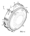
- FIGS 1 and 2 illustrate a tire extraction ring 10 suitable for removing a tire from a tire building drum (not shown).
- the tire extraction ring 10 is particularly suitable for large heavy tires, particularly tires having a size greater than 127 cm in diameter.
- the tire ring extractor 10 is formed of one or more arcuate segments 12 which are assembled together to form an annular ring.
- the segments 12 are preferably formed of steel meeting the standard of a pressure vessel grade weldment.
- One of the segments 12, segment 13 for instance, preferably has a flanged end 14 with a hole 16 for receiving a hook of a crane.
- Two of the segments preferably have diametrically opposed support rods or trunnions 18 which are welded to the segments.
- the support rods have an outer annular surface 20 which has an annular gear.
- the annular gear can be connected to drive means (not shown) for articulating the angle of the extraction ring from a vertical position to a horizontal position or any angle as desired.
- the tire extractor ring further preferably comprises a plurality of retention arms 40 which prevent the tire from falling out when the tire extractor ring is rotated horizontally as shown in Fig. 10.
- the retention arms 40 are pivotally mounted to the exterior of the extractor ring so that they can pivot 180 degrees and out of the way of the tire.
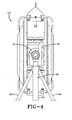
- FIGS 3 and 4 illustrate the tire ring extractor 10 mounted in a first and second tripod support stand 30.
- the tripod support stand 30 has an upper portion having a J shaped hook 32.
- the tripod support stands are positioned with respect to a tire extractor ring so that as the tire extractor ring is lowered via a crane, the opposed trunnions are lowered until they are received within the interior portion 31 of the J shaped hooks.
- the J shaped hooks allow for the rotation of the tire extractor ring.
- the J shaped hooks are supported by three support legs 34.
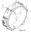
- the tire ring extractor further comprises a bladder 50 located on the internal surface of the tire extractor ring 10.
- the bladder 50 functions as a clamp to retain the tire in place when in the inflated position.
- the bladder 50 is shown unassembled in Fig. 7 .
- the bladder 50 is formed from an annular flexible sleeve preferably made of rubber or elastomer.
- the bladder material may preferably comprise textile reinforcements such as nylon or aramid.
- On the exterior surface 54 of the bladder there is a cord layer 56, preferably formed of high strength reinforcements such as steel. The steel cords are parallel and are oriented at a low angle with respect to the circumferential direction of the annular bladder in its assembled condition.
- the angle of the reinforcements is in the range of 0 degrees to 90 degrees, and more preferably in the range of 30 to 60 degrees as measured relative to the circumferential direction.
- the one or more reinforcement layers preferably have a width 2/3 the width of the bladder.
- the outer ends of the bladder preferably comprise rubber feet 52 which are received within receptacles 55 in an annular support flange 60.
- Figure 5 illustrates the bladder in the inflated condition and in engagement with a portion of a tire, while Figures 6 and 8 illustrates the bladder in the uninflated condition.
- the annular support flange 60 has one or more circumferentially spaced interior passageways 62 for supplying air to the bladder.
- a crane or other lifting device lifts the empty tire extractor ring into close proximity of a tire building drum.
- the extractor ring is lowered until the center of the extractor ring aligns with the center of the tire built on the tire building drum.
- the extractor ring is then slid over the outer circumference of the tire.
- the bladder 50 of the extractor ring is then inflated to fully engage the tire, and the tire building drum is actuated into a smaller diameter position.
- the tire extractor ring then removes the tire from the tire building drum.
Description
- The invention relates to the field of manufacturing, and more particularly to tire manufacturing.
- In tire manufacturing, after a green tire is made, it is removed from the tire building drum and sent to the tire curing press typically via an automated process such as a conveyor belt. For very large tires such as earth mover tires, the typical automated process will not suffice due to the size and weight of the tire. Very large tires having a diameter over 127 cm need to be moved from the tire building machine to the tire mold and then manipulated into the mold. Thus it is desired to have a tire extraction apparatus to remove the green tire from the tire building drum and being capable of storing the green tire for short period of time without damaging the tire.
-
GB-A-2030 106 SU-A- 1162615 - The invention relates to a device in accordance with claim 1 and to a method in accordance with
claim 12. - Dependent claims refer to preferred embodiments of the invention.
- "Aspect Ratio" means the ratio of a tire's section height to its section width.
- "Axial" and "axially" means the lines or directions that are parallel to the axis of rotation of the tire.
- "Radial" and "radially" mean directions radially toward or away from the axis of rotation of the tire.
- The invention will be described by way of example and with reference to the accompanying drawings in which:
-
FIG. 1 is a perspective view of a tire extractor device of the present invention shown with a tire; -
FIG. 2 is a perspective view of a tire extractor device of the present invention shown without a tire; -
FIG. 3 is front view of the tire extractor device shown together in a support frame device; -
FIG. 4 is a is side view of the tire extractor device and the support frame device; -
FIG. 5 is a cross-sectional view of the bladder assembly shown in the inflated position in conjunction with a portion of a tire; -
FIG. 6 is a cross-sectional view of the bladder assembly shown in the uninflated position in conjunction with a tire; -
FIG. 7 is a cross-sectional view of the bladder in the unassembled position; and -
FIG. 8 is a front view of the tire extractor ring with a tire mounted therein and shown in the horizontal position. -
Figures 1 and2 illustrate atire extraction ring 10 suitable for removing a tire from a tire building drum (not shown). Thetire extraction ring 10 is particularly suitable for large heavy tires, particularly tires having a size greater than 127 cm in diameter. Thetire ring extractor 10 is formed of one or morearcuate segments 12 which are assembled together to form an annular ring. Thesegments 12 are preferably formed of steel meeting the standard of a pressure vessel grade weldment. One of thesegments 12,segment 13 for instance, preferably has aflanged end 14 with ahole 16 for receiving a hook of a crane. Two of the segments preferably have diametrically opposed support rods ortrunnions 18 which are welded to the segments. The support rods have an outerannular surface 20 which has an annular gear. The annular gear can be connected to drive means (not shown) for articulating the angle of the extraction ring from a vertical position to a horizontal position or any angle as desired. The tire extractor ring further preferably comprises a plurality ofretention arms 40 which prevent the tire from falling out when the tire extractor ring is rotated horizontally as shown in Fig. 10. Theretention arms 40 are pivotally mounted to the exterior of the extractor ring so that they can pivot 180 degrees and out of the way of the tire. -
Figures 3 and4 illustrate thetire ring extractor 10 mounted in a first and second tripod support stand 30. Thetripod support stand 30 has an upper portion having a J shapedhook 32. The tripod support stands are positioned with respect to a tire extractor ring so that as the tire extractor ring is lowered via a crane, the opposed trunnions are lowered until they are received within theinterior portion 31 of the J shaped hooks. The J shaped hooks allow for the rotation of the tire extractor ring. The J shaped hooks are supported by threesupport legs 34. - As shown in
Figure 2 , the tire ring extractor further comprises abladder 50 located on the internal surface of thetire extractor ring 10. Thebladder 50 functions as a clamp to retain the tire in place when in the inflated position. Thebladder 50 is shown unassembled inFig. 7 . Thebladder 50 is formed from an annular flexible sleeve preferably made of rubber or elastomer. The bladder material may preferably comprise textile reinforcements such as nylon or aramid. On theexterior surface 54 of the bladder there is acord layer 56, preferably formed of high strength reinforcements such as steel. The steel cords are parallel and are oriented at a low angle with respect to the circumferential direction of the annular bladder in its assembled condition. More preferably, the angle of the reinforcements is in the range of 0 degrees to 90 degrees, and more preferably in the range of 30 to 60 degrees as measured relative to the circumferential direction. Preferably, there are two layers of steel cord. The one or more reinforcement layers preferably have a width 2/3 the width of the bladder. The outer ends of the bladder preferably compriserubber feet 52 which are received withinreceptacles 55 in anannular support flange 60.Figure 5 illustrates the bladder in the inflated condition and in engagement with a portion of a tire, whileFigures 6 and8 illustrates the bladder in the uninflated condition. Theannular support flange 60 has one or more circumferentially spacedinterior passageways 62 for supplying air to the bladder. - During operation, a crane or other lifting device lifts the empty tire extractor ring into close proximity of a tire building drum. The extractor ring is lowered until the center of the extractor ring aligns with the center of the tire built on the tire building drum. The extractor ring is then slid over the outer circumference of the tire. The
bladder 50 of the extractor ring is then inflated to fully engage the tire, and the tire building drum is actuated into a smaller diameter position. The tire extractor ring then removes the tire from the tire building drum.
Claims (13)
- A tire support device comprising a support member having an inner surface and an outer surface, a support flange (60) mounted to the support member, the support flange (60) having an inflatable bladder (50) mounted thereto, wherein the inflatable bladder (50) is inflatable to an inflated position for supporting a tire and has an outer surface coming into contact with the tire when the bladder (50) is inflated, wherein the inflatable bladder (50) is uninflatable to an uninflated position for releasing the tire, and wherein the bladder has an axial width extending in parallel to the axial direction of the tire, characterized in that the outer surface of the inflatable bladder (50) coming into contact with the tire when the bladder (50) is inflated has a layer (56) of cord reinforcements, the layer (56) of cord reinforcements having an axial width extending in parallel to the axial direction of the tire, in that the layer (56) of cord reinforcements comes into contact with the tire over its axial full width when the bladder (50) is inflated, and in that the axial width the layer (56) of cord reinforcements is less than the axial width of the bladder (50).
- The tire support device of claim 1 wherein the support member is annular.
- The tire support device of claim 1 or 2 wherein the support flange (60) is annular.
- The tire support device of clam 1, 2 or 3 wherein the inflatable bladder (50) is annular.
- The tire support device of at least one of the previous claims wherein the support member has opposed trunnions (18) mounted on the outer surface.
- The tire support device of at least one of the previous claims wherein the inflatable bladder (50) comprises textile reinforcements.
- The tire support device of claim 6 wherein the textile reinforcements are angled in range of 0 to 90 degrees with respect to circumferential direction.
- The tire support device of claim 1 wherein the cord reinforcements are steel reinforcements.
- The tire support device of claim 1 further comprising a first and second support stand, wherein the tire support device is rotatably mounted within the support stands.
- The tire support device of claim 2 or 3 wherein the annular support flange is mounted to the inner surface of the support member.
- The tire support device of claim 1 wherein the support device is configured to receive tires having a diameter of 127 cm or more.
- A method of manufacturing a tire, the method comprising:building a tire on a tire building drum;lifting an empty tire support device (10) in accordance with at least one of the previous claims into close proximity of the tire building drum;aligning the tire support device (10) with the center of the tire on the tire building drum;sliding the tire support device (10) over the outer circumference of the tire on the tire building drum;inflating the bladder (50) of the tire support device (10) to fully engage the tire on the tire building drum;actuating the tire building drum into a smaller diameter position;extracting the tire from the tire building drum using the tire support device (10).
- The method of claim 12 wherein the tire is a tire having a diameter of 127 cm or more.
Applications Claiming Priority (1)
| Application Number | Priority Date | Filing Date | Title |
|---|---|---|---|
| US12/965,044 US20120145328A1 (en) | 2010-12-10 | 2010-12-10 | Tire extractor apparatus |
Publications (2)
| Publication Number | Publication Date |
|---|---|
| EP2463085A1 EP2463085A1 (en) | 2012-06-13 |
| EP2463085B1 true EP2463085B1 (en) | 2014-01-15 |
Family
ID=45218341
Family Applications (1)
| Application Number | Title | Priority Date | Filing Date |
|---|---|---|---|
| EP11191477.6A Not-in-force EP2463085B1 (en) | 2010-12-10 | 2011-12-01 | Tire extractor apparatus and method of manufacturing a tire |
Country Status (5)
| Country | Link |
|---|---|
| US (1) | US20120145328A1 (en) |
| EP (1) | EP2463085B1 (en) |
| JP (1) | JP2012126135A (en) |
| CN (1) | CN102555251B (en) |
| BR (1) | BRPI1107096A2 (en) |
Families Citing this family (4)
| Publication number | Priority date | Publication date | Assignee | Title |
|---|---|---|---|---|
| JP5991910B2 (en) * | 2012-12-13 | 2016-09-14 | 住友ゴム工業株式会社 | Method of releasing vulcanized tire |
| JP6118570B2 (en) * | 2013-02-01 | 2017-04-19 | 株式会社ブリヂストン | Raw tire support device and method for removing drum from raw tire |
| SK288891B6 (en) * | 2017-11-07 | 2021-08-25 | Mesnac European Research And Technical Centre S.R.O. | Transportable device of the belt-tread pack in production of radial tyre casing |
| NL2028684B1 (en) * | 2021-07-09 | 2023-01-16 | Vmi Holland Bv | Tire unloading unit for unloading a green tire |
Family Cites Families (25)
| Publication number | Priority date | Publication date | Assignee | Title |
|---|---|---|---|---|
| US1458732A (en) * | 1923-06-12 | sloper | ||
| US1785659A (en) * | 1929-02-12 | 1930-12-16 | Goodyear Tire & Rubber | Tire-building machine |
| US2756883A (en) * | 1953-06-17 | 1956-07-31 | Irvin F Schreck | Vat lifting and dumping truck |
| US3059274A (en) * | 1959-08-10 | 1962-10-23 | James C Heintz Company | Mold dolly |
| FR1311177A (en) * | 1961-07-04 | 1962-12-07 | Dunlop Sa | Device for applying tire casing elements |
| US3253851A (en) * | 1963-11-07 | 1966-05-31 | Presray Corp | Rotating sling |
| US3475254A (en) * | 1965-01-05 | 1969-10-28 | Gen Tire & Rubber Co | Tire building machine |
| GB1149385A (en) * | 1965-07-17 | 1969-04-23 | Dunlop Co Ltd | Method of and apparatus for longitudinally compressing the filaments of rubberised textile filamentary fabric e.g. in tyre manufacture |
| US3990930A (en) * | 1971-09-09 | 1976-11-09 | The Goodyear Tire & Rubber Company | Bladder for tire building apparatus and method of making the same |
| US3809592A (en) * | 1972-04-04 | 1974-05-07 | Denbilt Corp | Process and apparatus for retreading tires |
| US3915311A (en) * | 1974-01-21 | 1975-10-28 | Caterpillar Tractor Co | Method and apparatus for handling large, fragile objects |
| US4148681A (en) * | 1977-07-05 | 1979-04-10 | Eaton Corporation | Expandable carrier apparatus for a tire building machine |
| US4204903A (en) * | 1978-09-22 | 1980-05-27 | The General Tire & Rubber Company | Apparatus and method for handling uncured tires |
| SU1162615A1 (en) * | 1983-10-10 | 1985-06-23 | Предприятие П/Я А-3404 | Apparatus for retaining pneumatic tyres |
| US4830693A (en) * | 1985-11-08 | 1989-05-16 | Bridgestone Corporation | Method for forming a tire around a bead |
| US4877469A (en) * | 1987-03-18 | 1989-10-31 | The Armstrong Rubber Company | Reinforced tire curing bladder and method for using same |
| JPH02297427A (en) * | 1989-02-21 | 1990-12-07 | Toyo Tire & Rubber Co Ltd | Air bladder for forming tire |
| US5380383A (en) * | 1994-04-01 | 1995-01-10 | The Goodyear Tire & Rubber Company | Tread application method |
| JP2003071948A (en) * | 2001-09-04 | 2003-03-12 | Yokohama Rubber Co Ltd:The | Member contact bonding apparatus for tire molding machine |
| CN1750923A (en) * | 2003-03-10 | 2006-03-22 | 倍耐力轮胎公司 | Method and apparatus for manufacturing tyres for vehicle wheels |
| JP4359286B2 (en) * | 2003-10-31 | 2009-11-04 | ピレリ・タイヤ・ソチエタ・ペル・アツィオーニ | Inflatable bladder for tire vulcanizer, method for producing the same, and process for producing tires for wheels |
| DE102004058522A1 (en) * | 2004-12-04 | 2006-06-14 | Continental Aktiengesellschaft | Method and device for constructing a radial tire |
| DE102005001377A1 (en) * | 2005-01-12 | 2006-07-20 | Continental Aktiengesellschaft | Process for producing a tire with tire building parts |
| EP1855874A1 (en) * | 2005-02-28 | 2007-11-21 | PIRELLI TYRE S.p.A. | Method and apparatus for manufacturing pneumatic tyres for vehicule wheels |
| JP2007022045A (en) * | 2005-07-21 | 2007-02-01 | Sumitomo Rubber Ind Ltd | Shaping bladder for tire manufacture and tire manufacturing method |
-
2010
- 2010-12-10 US US12/965,044 patent/US20120145328A1/en not_active Abandoned
-
2011
- 2011-11-30 BR BRPI1107096-0A patent/BRPI1107096A2/en not_active IP Right Cessation
- 2011-12-01 EP EP11191477.6A patent/EP2463085B1/en not_active Not-in-force
- 2011-12-07 JP JP2011267625A patent/JP2012126135A/en active Pending
- 2011-12-09 CN CN201110408335.3A patent/CN102555251B/en not_active Expired - Fee Related
Also Published As
| Publication number | Publication date |
|---|---|
| CN102555251B (en) | 2015-08-26 |
| BRPI1107096A2 (en) | 2013-05-28 |
| JP2012126135A (en) | 2012-07-05 |
| CN102555251A (en) | 2012-07-11 |
| US20120145328A1 (en) | 2012-06-14 |
| EP2463085A1 (en) | 2012-06-13 |
Similar Documents
| Publication | Publication Date | Title |
|---|---|---|
| EP2463085B1 (en) | Tire extractor apparatus and method of manufacturing a tire | |
| JP5698287B2 (en) | Raw tire shape correction method and apparatus | |
| CN108638102B (en) | Automobile tire grabbing device | |
| US3945866A (en) | Tire building apparatus for large tires | |
| US10350844B2 (en) | Green tire support device and method of removing drum from green tire | |
| JP6504954B2 (en) | Method and device for preforming diaphragm for air spring, and method for manufacturing diaphragm for air spring | |
| EP1500527B1 (en) | Improved method of changing tread on very large tires | |
| EP1749647A1 (en) | Tire bead stretcher and method for holding a green tire | |
| JP6522453B2 (en) | Device for manufacturing diaphragm for air spring and method for attaching and detaching bead ring in the manufacturing | |
| CN112357821B (en) | PCCP spiral welding and water pressure inspection automatic assembly line and application method thereof | |
| JP4904666B2 (en) | Pneumatic tire reversing device | |
| CN101462367B (en) | Tire building core assembly and disassembly station and method | |
| CN205892583U (en) | A base for christmas tree or production tree hoist device | |
| US4425954A (en) | Method and apparatus for mounting tires on rims | |
| US8936286B2 (en) | Device and method for handling an uncured tire blank | |
| KR101797479B1 (en) | Turn over apparatus with double turning ring for turning over propeller of ship | |
| KR100229261B1 (en) | Tower-type device for conveying concrete | |
| EP2329941A1 (en) | Apparatus for cooling a tire, tire building press with such an apparatus and method of manufacturing a tire | |
| US4378834A (en) | Wheel assembly machine and method | |
| KR101868937B1 (en) | Apparatus for Handling Roll | |
| JP5126966B2 (en) | Storage device and storage method for unvulcanized tires | |
| JP3110753B2 (en) | Method and apparatus for coating a concrete layer on the outer surface of an elongated body | |
| CN103660334A (en) | Method for preforming a green tire | |
| JP2021095937A (en) | Pipe centering jig and centering method | |
| CN206033064U (en) | A hoist device for christmas tree or production tree |
Legal Events
| Date | Code | Title | Description |
|---|---|---|---|
| PUAI | Public reference made under article 153(3) epc to a published international application that has entered the european phase |
Free format text: ORIGINAL CODE: 0009012 |
|
| AK | Designated contracting states |
Kind code of ref document: A1 Designated state(s): AL AT BE BG CH CY CZ DE DK EE ES FI FR GB GR HR HU IE IS IT LI LT LU LV MC MK MT NL NO PL PT RO RS SE SI SK SM TR |
|
| AX | Request for extension of the european patent |
Extension state: BA ME |
|
| 17P | Request for examination filed |
Effective date: 20121213 |
|
| GRAP | Despatch of communication of intention to grant a patent |
Free format text: ORIGINAL CODE: EPIDOSNIGR1 |
|
| RIC1 | Information provided on ipc code assigned before grant |
Ipc: B29D 30/00 20060101ALN20130612BHEP Ipc: B29D 30/26 20060101AFI20130612BHEP |
|
| INTG | Intention to grant announced |
Effective date: 20130704 |
|
| GRAS | Grant fee paid |
Free format text: ORIGINAL CODE: EPIDOSNIGR3 |
|
| GRAA | (expected) grant |
Free format text: ORIGINAL CODE: 0009210 |
|
| AK | Designated contracting states |
Kind code of ref document: B1 Designated state(s): AL AT BE BG CH CY CZ DE DK EE ES FI FR GB GR HR HU IE IS IT LI LT LU LV MC MK MT NL NO PL PT RO RS SE SI SK SM TR |
|
| REG | Reference to a national code |
Ref country code: GB Ref legal event code: FG4D Ref country code: CH Ref legal event code: EP |
|
| REG | Reference to a national code |
Ref country code: AT Ref legal event code: REF Ref document number: 649607 Country of ref document: AT Kind code of ref document: T Effective date: 20140215 |
|
| REG | Reference to a national code |
Ref country code: IE Ref legal event code: FG4D |
|
| REG | Reference to a national code |
Ref country code: DE Ref legal event code: R096 Ref document number: 602011004695 Country of ref document: DE Effective date: 20140227 |
|
| REG | Reference to a national code |
Ref country code: NL Ref legal event code: VDEP Effective date: 20140115 |
|
| REG | Reference to a national code |
Ref country code: AT Ref legal event code: MK05 Ref document number: 649607 Country of ref document: AT Kind code of ref document: T Effective date: 20140115 |
|
| REG | Reference to a national code |
Ref country code: LT Ref legal event code: MG4D |
|
| PG25 | Lapsed in a contracting state [announced via postgrant information from national office to epo] |
Ref country code: LT Free format text: LAPSE BECAUSE OF FAILURE TO SUBMIT A TRANSLATION OF THE DESCRIPTION OR TO PAY THE FEE WITHIN THE PRESCRIBED TIME-LIMIT Effective date: 20140115 Ref country code: NO Free format text: LAPSE BECAUSE OF FAILURE TO SUBMIT A TRANSLATION OF THE DESCRIPTION OR TO PAY THE FEE WITHIN THE PRESCRIBED TIME-LIMIT Effective date: 20140415 Ref country code: IS Free format text: LAPSE BECAUSE OF FAILURE TO SUBMIT A TRANSLATION OF THE DESCRIPTION OR TO PAY THE FEE WITHIN THE PRESCRIBED TIME-LIMIT Effective date: 20140515 |
|
| PG25 | Lapsed in a contracting state [announced via postgrant information from national office to epo] |
Ref country code: NL Free format text: LAPSE BECAUSE OF FAILURE TO SUBMIT A TRANSLATION OF THE DESCRIPTION OR TO PAY THE FEE WITHIN THE PRESCRIBED TIME-LIMIT Effective date: 20140115 Ref country code: AT Free format text: LAPSE BECAUSE OF FAILURE TO SUBMIT A TRANSLATION OF THE DESCRIPTION OR TO PAY THE FEE WITHIN THE PRESCRIBED TIME-LIMIT Effective date: 20140115 Ref country code: SE Free format text: LAPSE BECAUSE OF FAILURE TO SUBMIT A TRANSLATION OF THE DESCRIPTION OR TO PAY THE FEE WITHIN THE PRESCRIBED TIME-LIMIT Effective date: 20140115 Ref country code: CY Free format text: LAPSE BECAUSE OF FAILURE TO SUBMIT A TRANSLATION OF THE DESCRIPTION OR TO PAY THE FEE WITHIN THE PRESCRIBED TIME-LIMIT Effective date: 20140115 Ref country code: ES Free format text: LAPSE BECAUSE OF FAILURE TO SUBMIT A TRANSLATION OF THE DESCRIPTION OR TO PAY THE FEE WITHIN THE PRESCRIBED TIME-LIMIT Effective date: 20140115 Ref country code: PT Free format text: LAPSE BECAUSE OF FAILURE TO SUBMIT A TRANSLATION OF THE DESCRIPTION OR TO PAY THE FEE WITHIN THE PRESCRIBED TIME-LIMIT Effective date: 20140515 Ref country code: FI Free format text: LAPSE BECAUSE OF FAILURE TO SUBMIT A TRANSLATION OF THE DESCRIPTION OR TO PAY THE FEE WITHIN THE PRESCRIBED TIME-LIMIT Effective date: 20140115 |
|
| PG25 | Lapsed in a contracting state [announced via postgrant information from national office to epo] |
Ref country code: LV Free format text: LAPSE BECAUSE OF FAILURE TO SUBMIT A TRANSLATION OF THE DESCRIPTION OR TO PAY THE FEE WITHIN THE PRESCRIBED TIME-LIMIT Effective date: 20140115 Ref country code: BE Free format text: LAPSE BECAUSE OF FAILURE TO SUBMIT A TRANSLATION OF THE DESCRIPTION OR TO PAY THE FEE WITHIN THE PRESCRIBED TIME-LIMIT Effective date: 20140115 Ref country code: RS Free format text: LAPSE BECAUSE OF FAILURE TO SUBMIT A TRANSLATION OF THE DESCRIPTION OR TO PAY THE FEE WITHIN THE PRESCRIBED TIME-LIMIT Effective date: 20140115 Ref country code: HR Free format text: LAPSE BECAUSE OF FAILURE TO SUBMIT A TRANSLATION OF THE DESCRIPTION OR TO PAY THE FEE WITHIN THE PRESCRIBED TIME-LIMIT Effective date: 20140115 |
|
| REG | Reference to a national code |
Ref country code: DE Ref legal event code: R097 Ref document number: 602011004695 Country of ref document: DE |
|
| PG25 | Lapsed in a contracting state [announced via postgrant information from national office to epo] |
Ref country code: EE Free format text: LAPSE BECAUSE OF FAILURE TO SUBMIT A TRANSLATION OF THE DESCRIPTION OR TO PAY THE FEE WITHIN THE PRESCRIBED TIME-LIMIT Effective date: 20140115 Ref country code: RO Free format text: LAPSE BECAUSE OF FAILURE TO SUBMIT A TRANSLATION OF THE DESCRIPTION OR TO PAY THE FEE WITHIN THE PRESCRIBED TIME-LIMIT Effective date: 20140115 Ref country code: CZ Free format text: LAPSE BECAUSE OF FAILURE TO SUBMIT A TRANSLATION OF THE DESCRIPTION OR TO PAY THE FEE WITHIN THE PRESCRIBED TIME-LIMIT Effective date: 20140115 Ref country code: DK Free format text: LAPSE BECAUSE OF FAILURE TO SUBMIT A TRANSLATION OF THE DESCRIPTION OR TO PAY THE FEE WITHIN THE PRESCRIBED TIME-LIMIT Effective date: 20140115 |
|
| PLBE | No opposition filed within time limit |
Free format text: ORIGINAL CODE: 0009261 |
|
| STAA | Information on the status of an ep patent application or granted ep patent |
Free format text: STATUS: NO OPPOSITION FILED WITHIN TIME LIMIT |
|
| PG25 | Lapsed in a contracting state [announced via postgrant information from national office to epo] |
Ref country code: PL Free format text: LAPSE BECAUSE OF FAILURE TO SUBMIT A TRANSLATION OF THE DESCRIPTION OR TO PAY THE FEE WITHIN THE PRESCRIBED TIME-LIMIT Effective date: 20140115 Ref country code: SK Free format text: LAPSE BECAUSE OF FAILURE TO SUBMIT A TRANSLATION OF THE DESCRIPTION OR TO PAY THE FEE WITHIN THE PRESCRIBED TIME-LIMIT Effective date: 20140115 |
|
| 26N | No opposition filed |
Effective date: 20141016 |
|
| REG | Reference to a national code |
Ref country code: DE Ref legal event code: R097 Ref document number: 602011004695 Country of ref document: DE Effective date: 20141016 |
|
| PG25 | Lapsed in a contracting state [announced via postgrant information from national office to epo] |
Ref country code: SI Free format text: LAPSE BECAUSE OF FAILURE TO SUBMIT A TRANSLATION OF THE DESCRIPTION OR TO PAY THE FEE WITHIN THE PRESCRIBED TIME-LIMIT Effective date: 20140115 |
|
| PG25 | Lapsed in a contracting state [announced via postgrant information from national office to epo] |
Ref country code: LU Free format text: LAPSE BECAUSE OF FAILURE TO SUBMIT A TRANSLATION OF THE DESCRIPTION OR TO PAY THE FEE WITHIN THE PRESCRIBED TIME-LIMIT Effective date: 20141201 |
|
| REG | Reference to a national code |
Ref country code: CH Ref legal event code: PL |
|
| REG | Reference to a national code |
Ref country code: IE Ref legal event code: MM4A |
|
| PG25 | Lapsed in a contracting state [announced via postgrant information from national office to epo] |
Ref country code: LI Free format text: LAPSE BECAUSE OF NON-PAYMENT OF DUE FEES Effective date: 20141231 Ref country code: IE Free format text: LAPSE BECAUSE OF NON-PAYMENT OF DUE FEES Effective date: 20141201 Ref country code: CH Free format text: LAPSE BECAUSE OF NON-PAYMENT OF DUE FEES Effective date: 20141231 |
|
| REG | Reference to a national code |
Ref country code: FR Ref legal event code: PLFP Year of fee payment: 5 |
|
| PG25 | Lapsed in a contracting state [announced via postgrant information from national office to epo] |
Ref country code: SM Free format text: LAPSE BECAUSE OF FAILURE TO SUBMIT A TRANSLATION OF THE DESCRIPTION OR TO PAY THE FEE WITHIN THE PRESCRIBED TIME-LIMIT Effective date: 20140115 |
|
| PG25 | Lapsed in a contracting state [announced via postgrant information from national office to epo] |
Ref country code: MC Free format text: LAPSE BECAUSE OF FAILURE TO SUBMIT A TRANSLATION OF THE DESCRIPTION OR TO PAY THE FEE WITHIN THE PRESCRIBED TIME-LIMIT Effective date: 20140115 |
|
| PG25 | Lapsed in a contracting state [announced via postgrant information from national office to epo] |
Ref country code: BG Free format text: LAPSE BECAUSE OF FAILURE TO SUBMIT A TRANSLATION OF THE DESCRIPTION OR TO PAY THE FEE WITHIN THE PRESCRIBED TIME-LIMIT Effective date: 20140115 Ref country code: GR Free format text: LAPSE BECAUSE OF FAILURE TO SUBMIT A TRANSLATION OF THE DESCRIPTION OR TO PAY THE FEE WITHIN THE PRESCRIBED TIME-LIMIT Effective date: 20140416 |
|
| PG25 | Lapsed in a contracting state [announced via postgrant information from national office to epo] |
Ref country code: MT Free format text: LAPSE BECAUSE OF FAILURE TO SUBMIT A TRANSLATION OF THE DESCRIPTION OR TO PAY THE FEE WITHIN THE PRESCRIBED TIME-LIMIT Effective date: 20140115 Ref country code: HU Free format text: LAPSE BECAUSE OF FAILURE TO SUBMIT A TRANSLATION OF THE DESCRIPTION OR TO PAY THE FEE WITHIN THE PRESCRIBED TIME-LIMIT; INVALID AB INITIO Effective date: 20111201 Ref country code: TR Free format text: LAPSE BECAUSE OF FAILURE TO SUBMIT A TRANSLATION OF THE DESCRIPTION OR TO PAY THE FEE WITHIN THE PRESCRIBED TIME-LIMIT Effective date: 20140115 |
|
| GBPC | Gb: european patent ceased through non-payment of renewal fee |
Effective date: 20151201 |
|
| PG25 | Lapsed in a contracting state [announced via postgrant information from national office to epo] |
Ref country code: GB Free format text: LAPSE BECAUSE OF NON-PAYMENT OF DUE FEES Effective date: 20151201 |
|
| REG | Reference to a national code |
Ref country code: FR Ref legal event code: PLFP Year of fee payment: 6 |
|
| REG | Reference to a national code |
Ref country code: FR Ref legal event code: PLFP Year of fee payment: 7 |
|
| PGFP | Annual fee paid to national office [announced via postgrant information from national office to epo] |
Ref country code: DE Payment date: 20171221 Year of fee payment: 7 |
|
| PG25 | Lapsed in a contracting state [announced via postgrant information from national office to epo] |
Ref country code: MK Free format text: LAPSE BECAUSE OF FAILURE TO SUBMIT A TRANSLATION OF THE DESCRIPTION OR TO PAY THE FEE WITHIN THE PRESCRIBED TIME-LIMIT Effective date: 20140115 |
|
| REG | Reference to a national code |
Ref country code: FR Ref legal event code: PLFP Year of fee payment: 8 |
|
| PG25 | Lapsed in a contracting state [announced via postgrant information from national office to epo] |
Ref country code: AL Free format text: LAPSE BECAUSE OF FAILURE TO SUBMIT A TRANSLATION OF THE DESCRIPTION OR TO PAY THE FEE WITHIN THE PRESCRIBED TIME-LIMIT Effective date: 20140115 |
|
| PGFP | Annual fee paid to national office [announced via postgrant information from national office to epo] |
Ref country code: FR Payment date: 20181011 Year of fee payment: 8 |
|
| PGFP | Annual fee paid to national office [announced via postgrant information from national office to epo] |
Ref country code: IT Payment date: 20181220 Year of fee payment: 8 |
|
| REG | Reference to a national code |
Ref country code: DE Ref legal event code: R119 Ref document number: 602011004695 Country of ref document: DE |
|
| PG25 | Lapsed in a contracting state [announced via postgrant information from national office to epo] |
Ref country code: DE Free format text: LAPSE BECAUSE OF NON-PAYMENT OF DUE FEES Effective date: 20190702 |
|
| PG25 | Lapsed in a contracting state [announced via postgrant information from national office to epo] |
Ref country code: IT Free format text: LAPSE BECAUSE OF NON-PAYMENT OF DUE FEES Effective date: 20191201 Ref country code: FR Free format text: LAPSE BECAUSE OF NON-PAYMENT OF DUE FEES Effective date: 20191231 |