EP2463042A1 - Assembly jig for pins for power transmission chain - Google Patents
Assembly jig for pins for power transmission chain Download PDFInfo
- Publication number
- EP2463042A1 EP2463042A1 EP11192515A EP11192515A EP2463042A1 EP 2463042 A1 EP2463042 A1 EP 2463042A1 EP 11192515 A EP11192515 A EP 11192515A EP 11192515 A EP11192515 A EP 11192515A EP 2463042 A1 EP2463042 A1 EP 2463042A1
- Authority
- EP
- European Patent Office
- Prior art keywords
- pins
- pin
- recesses
- pin insertion
- link
- Prior art date
- Legal status (The legal status is an assumption and is not a legal conclusion. Google has not performed a legal analysis and makes no representation as to the accuracy of the status listed.)
- Granted
Links
- 230000005540 biological transmission Effects 0.000 title claims description 37
- 238000003780 insertion Methods 0.000 claims abstract description 87
- 230000037431 insertion Effects 0.000 claims abstract description 87
- 238000009434 installation Methods 0.000 claims abstract description 26
- 238000003825 pressing Methods 0.000 claims abstract description 26
- 238000005096 rolling process Methods 0.000 claims description 12
- 238000004519 manufacturing process Methods 0.000 claims description 8
- 230000006835 compression Effects 0.000 abstract description 8
- 238000007906 compression Methods 0.000 abstract description 8
- 229910000831 Steel Inorganic materials 0.000 description 4
- 229910001315 Tool steel Inorganic materials 0.000 description 4
- 230000014759 maintenance of location Effects 0.000 description 4
- 230000000717 retained effect Effects 0.000 description 4
- 239000010959 steel Substances 0.000 description 4
- OKTJSMMVPCPJKN-UHFFFAOYSA-N Carbon Chemical compound [C] OKTJSMMVPCPJKN-UHFFFAOYSA-N 0.000 description 3
- 229910052799 carbon Inorganic materials 0.000 description 3
- 230000007423 decrease Effects 0.000 description 3
- 229910000639 Spring steel Inorganic materials 0.000 description 2
- 238000007796 conventional method Methods 0.000 description 2
- 239000000463 material Substances 0.000 description 2
- 238000000034 method Methods 0.000 description 2
- 230000002093 peripheral effect Effects 0.000 description 2
- 229910045601 alloy Inorganic materials 0.000 description 1
- 239000000956 alloy Substances 0.000 description 1
Images



Classifications
-
- B—PERFORMING OPERATIONS; TRANSPORTING
- B21—MECHANICAL METAL-WORKING WITHOUT ESSENTIALLY REMOVING MATERIAL; PUNCHING METAL
- B21L—MAKING METAL CHAINS
- B21L9/00—Making chains or chain links, the links being composed of two or more different parts, e.g. drive chains
- B21L9/02—Making chains or chain links, the links being composed of two or more different parts, e.g. drive chains of roller-chain or other plate-link type
- B21L9/06—Sorting, feeding, assembling, riveting, or finishing parts of chains
- B21L9/065—Assembling or disassembling
-
- B—PERFORMING OPERATIONS; TRANSPORTING
- B21—MECHANICAL METAL-WORKING WITHOUT ESSENTIALLY REMOVING MATERIAL; PUNCHING METAL
- B21L—MAKING METAL CHAINS
- B21L19/00—Appurtenances for chain-making not restricted to any particular process
Definitions
- the invention relates generally to an assembly jig for pins for a power transmission chain, and more specifically to an assembly jig for pins for a power transmission chain suitable for a continuously variable transmission (CVT) of a vehicle such as an automobile.
- CVT continuously variable transmission
- a power transmission chain suitable for a continuously variable transmission for an automobile includes a plurality of links, a plurality of first pins, and a plurality of second pins.
- Each link has front and rear insertion portions through which the pins are passed.
- Each first pin and a corresponding one of the second pins are aligned next to each other in the longitudinal direction of the links, and connect the links, aligned in the chain width direction, to each other such that the front insertion portion of one link corresponds to the rear insertion portion of another link.
- the first pins and the second pins move while being in rolling contact with respect to each other, so that the links are flexural with respect to each other in the chain length direction.
- the chain is able to shift from the straight state to the curved state.
- one of a first pin and a second pin is fixed to a front insertion portion of one link through press-fitting and is movably fitted in a rear insertion portion of another link, and the other of the first pin and the second pin is movably fitted in the front insertion portion of the one link and is fixed to the rear insertion portion of the other link through press-fitting.
- Japanese Patent Application Publication No. 2006-95583 describes a method of manufacturing such a power transmission chain. According to the method, a required number of pins are arranged with a predetermined pitch (at predetermined intervals) so as to vertically extend, and held in the same arrangement state as that when the pins are assembled into a chain. Then, links are sequentially press-fitted one by one to these pins from the lower ends.
- Japanese Patent Application Publication No. 2006-95583 describes the following method of manufacturing a power transmission chain. According to the method, as shown in FIG. 7 , while an assembly jig 41 for pins is rotated, each pair of pins 14, 15 is inserted into a corresponding one of pin insertion recesses 42 formed in the assembly jig 41 with a predetermined pitch. In this way, all the pins 14, 15 that are used in a chain 1 are arranged on the assembly jig 41 for pins, and held in the same arrangement state as that when the pins 14, 15 are assembled into the chain 1. Then, as shown in FIG. 8 , links 11 used in the chain 1 are sequentially press-fitted to these pins 14, 15 by pressing jigs 45 such that the links 11 are laminated on top of each other in the chain width direction.
- the aforementioned conventional method of manufacturing a power transmission chain and the aforementioned conventional assembly jig for pins for a power transmission chain may cause the following inconvenience. That is, some pins that are loosely fitted in the assembly jig due to dimensional variations in manufacturing may topple down while the assembly jig for pins rotates. Accordingly, it is preferable to provide a device used to retain the pins. However, it is difficult to provide a retention device in such a manner that the retention device does not hinder press-fitting of the links by the pressing jigs. Therefore, retaining the pins with a compact and simple mechanism is a task that should be accomplished.
- An aspect of the invention relates to an assembly jig for pins, which is used to manufacture a power transmission chain that includes a plurality of links each having front and rear insertion portions through which pins are passed, and a plurality of first pins and a plurality of second pins.
- Each first pin and a corresponding one of the second pins are aligned next to each other in the longitudinal direction of the links, and the first pins and the second pins connect the links, aligned in the chain width direction, to each other such that the front insertion portion of one link corresponds to the rear insertion portion of another link.
- the first pins and the second pins move while being in rolling contact with respect to each other, so that the links are flexural with respect to each other in the chain length direction.
- the assembly jig includes a jig body in which pin insertion recesses, into which respective pairs of pins are inserted, are aligned at predetermined intervals.
- the jig body has urging device installation recesses formed so as to be contiguous with the respective pin insertion recesses. In each urging device installation recess, there is arranged an urging device that urges a lower end portion of the pin fitted in the pin insertion recess in the direction perpendicular to the axial direction of the pins.
- the up-and-down direction in a power transmission chain signifies the up-and-down direction in FIG. 2
- the up-and-down direction in an assembly jig for pins signifies the up-and-down direction in FIG. 5 .
- FIG. 1 shows part of a power transmission chain that is manufactured with the use of an assembly jig for pins for a power transmission chain according to the invention.
- a power transmission chain 1 includes a plurality of links 11, a plurality of pins (first pins) 14, and a plurality of interpieces (second pins) 15.
- Each link 11 has a front insertion portion 12 and a rear insertion portion 13 that are formed at a predetermined interval in the chain length direction.
- the pins (first pins) 14 and the interpieces (second pins) 15 connect the links 11, aligned in the chain width direction, to each other such that the links 11 are flexural with respect to each other in the chain length direction.
- the interpiece 15 is shorter than the pin 14.
- the interpiece 15 and the pin 14 face each other such that the interpiece 15 is arranged in front of the pin 14 in the chain traveling direction.
- the chain 1 is formed by arranging three link rows, each of which is constituted of a plurality of links having the same phase in the chain width direction, in the chain traveling direction (longitudinal direction) to constitute a single link unit, and connecting a plurality of link units, each of which is constituted of the three link rows, to each other in the chain traveling direction.
- one link row having nine links and two link rows each having eight links constitute a single link unit.
- the front insertion portion 12 of each link 11 is formed of a pin movable portion 16 to which one of the pins 14 is movably fitted, and an interpiece fixation portion 17 to which one of the interpieces 15 is fixed.
- the rear insertion portion 13 is formed of a pin fixation portion 18 to which another of the pins 14 is fixed, and an interpiece movable portion 19 to which another of the interpieces 15 is movably fitted.
- Each pin 14 is wider in the link longitudinal direction than each interpiece 15.
- Each interpiece 15 has, at its upper and lower edges, protruding edge portions 15a and 15b, respectively, which extend toward the corresponding pin 14.
- the links 11 are placed on top of each other such that the front insertion portion 12 of one link 11 corresponds to the rear insertion portion 13 of another link 11.
- the pin 14 is fixed to the rear insertion portion 13 of the one link 11 and is movably fitted to the front insertion portion 12 of the other link 11.
- the interpiece 15 is movably fitted to the rear insertion portion 13 of the one link 11 and fixed to the front insertion portion 12 of the other link 11. Then, the pin 14 and the interpiece 15 move while being in rolling contact with respect to each other, so that the links 11 are flexural with respect to each other in the chain length direction (longitudinal direction).
- the chain 1 is able to shift from the straight state to the curved state.
- a rolling contact surface 14a of the pin 14 is an involute curve having a base circle with a center M and a radius Rb in cross-section
- a rolling contact surface 15c of the interpiece 15 is a flat surface (of which the cross-sectional shape is rectilinear).
- the power transmission chain 1 is used in a continuously variable transmission (CVT).
- CVT continuously variable transmission
- end faces of each pin 14 are in contact with a conical sheave face 2c of a fixed sheave 2a of a drive pulley 2 having a pulley shaft 2e and a conical sheave face 2d of a movable sheave 2b of the drive pulley 2, with end faces of each interpiece 15 out of contact with the conical sheave faces 2c and 2d of the drive pulley 2.
- Power is transmitted under frictional force resulting from the contact between the end faces of each pin 14 and the conical sheave faces 2c, 2d.
- the running diameter of the circle of rotation of the drive pulley 2 increases as the movable sheave 2b moves toward the fixed sheave 2a, and decreases as the movable sheave 2b moves away from the fixed sheave 2a, as indicated by chain lines.
- a movable sheave of a driven pulley moves toward a fixed sheave as the movable sheave 2b of the drive pulley 2 moves away from the fixed sheave 2a, and moves away from the fixed shave as the movable sheave 2b moves toward the fixed sheave 2a.
- the running diameter of the circle of rotation of the drive pulley 2 increases, the running diameter of the circle of rotation of the driven pulley decreases.
- the running diameter of the circle of rotation of the driven pulley increases.
- the power transmission chain 1 is manufactured by retaining a required number of pins 14 and a required number of interpieces 15, and then sequentially press-fitting a required number of links 11 to the pins 14 and the interpieces 15.
- the links 11 are press-fitted to the pins 14 and the interpieces 15 such that the upper and lower edges of the pin 14 are fixed to the upper and lower edges of the pin fixation portion 18, respectively, and the upper and lower edges of the interpiece 15 are fixed to the upper and lower edges of the interpiece fixation portion 17, respectively, as shown in FIG. 2 .
- the press-fitting interference is set to 0.005 mm to 0.1 mm.
- a method of manufacturing the power transmission chain is similar to a conventional method, and includes a pin retaining step and a link press-fitting step.
- the pin retaining step all the pins 14 and interpieces 15 used in the chain 1 are grouped into multiple pairs each including one pin 14 and one interpiece 15, and the multiple pairs of pin 14 and interpiece 15 are arranged on an assembly jig 20 (30) for pins with a predetermined pitch (at predetermined intervals) and retained in the same arrangement state as that when the pins 14 and the interpieces 15 are assembled into the chain 1.
- the links 11 used in the chain 1 are sequentially press-fitted to the pins 14 and the interpieces 15 so as to be laminated on top of each other in the chain width direction.
- a conventional assembly jig 41 for pins is designed to retain the pins 14 and the interpieces 15 using only frictional forces generated by fitting the lower ends thereof into pin insertion recesses 42.
- urging devices 24 (34) that generate elastic forces are provided in the assembly jig 20 (30) for pins according to the invention, as will be described below.
- FIGS. 4 and 5 show the assembly jig 20 for pins for a power transmission chain according to a first embodiment of the invention.
- the assembly jig 20 for pins includes a jig body 21 and the urging devices 24.
- the jig body 21 pin insertion recesses 22, into which the respective pairs each including one pin 14 and one interpiece 15 are inserted, are formed at predetermined intervals.
- the urging device 24 urges the lower end portion of the interpiece 15 fitted in the pin insertion recess 22 in the direction perpendicular to the axial direction of the interpiece 15 (in the direction parallel to the upper face of the assembly jig 20 for pins).
- the jig body 21 has a circular shape (circular disc-shape).
- urging device installation recesses 23 are formed so as to be contiguous with the respective pin insertion recesses 22 in the direction in which the pin insertions recesses are aligned (in the circumferential direction of the jig body 21).
- the urging device installation recess 23 is formed next to a portion of the pin insertion recess 22, into which the interpiece 15 is inserted.
- the urging device installation recess 23 has an elongated shape with a narrow width, and extends inward in the radial direction of the jig body 21.
- Each urging device 24 may be a leaf spring, and is provided in the urging device installation recess 23 so as to be able to urge the interpiece 15 in the circumferential direction (the direction in which the pin insertion recesses 22 are aligned) and so as to be deformable in the direction away from the interpiece 15.
- Each pin insertion recess 22 has a bottom, and the depth thereof coincides with the amount (sticlc-out amount) by which the pin 14 and the interpiece 15 each stick out of the outermost one of the links 11 aligned in the chain width direction.
- the bottom face of each pin insertion recess 22 is stepped such that the pin 14 and the interpiece 15 stick out of the outermost link 11 by predetermined amounts.
- the transverse sectional shape of the pin insertion recess 22 is substantially the same as the shape of each of the front and rear insertion portions 12 and 13 of the link 11.
- the pin insertion recess 2 is formed such that the pin 14 and the interpiece 15 are able to be inserted into and removed from the pin insertion recess 22 and the inserted pin 14 and inter-pin 15 are immovable.
- the assembly jig 20 for pins is rotatable about its vertical axis.
- the pins 14 and the interpieces 15 are inserted into the respective pin insertion recesses 22 while the assembly jig 20 for pins is rotated.
- the links 11 are arranged at upper ends of the pins 14 and the interpieces 15 by a link supply device (not shown).
- link pressing jigs are lowered to move the links 11 to predetermined positions.
- rotation of the assembly jig 20 for pins by a predetermined amount, arrangement of the links 11, and lowering of the link pressing jigs are repeated to assemble the power transmission chain 1.
- the transverse sectional shape of the pin insertion recess 22 is designed such that the inserted pin 14 and interpiece 15 are immovable.
- some pins 14 and interpieces 15 that are loosely fitted in the assembly jig 20 due to dimensional variations in manufacturing may topple down while the assembly jig 20 for pins rotates.
- the lower end portion of one of the paired pin 14 and interpiece 15 is pressed by the leaf spring 24 that serves as the urging device in such a direction as to press the other one of the paired pin 14 and the interpiece 15(pin 14, in the first embodiment).
- the lower end portion of the pin 14 is pressed to the peripheral face of the pin insertion recess 22, so that the lower end portions of both the pin 14 and the interpiece 15 are retained within the pin insertion recess 22.
- the pin 14 and the interpiece 15 no longer topple down.
- the leaf spring 24 is provided in the urging device installation recess 23, and therefore does not stick out of the upper face of the jig body 21, that is, does not hinder press-fitting of the links 11, which is performed using pressing jigs in a link press-fitting step.
- the interval between the consecutive pin insertion recesses 22 is determined based on the dimension of the power transmission chain 1. Therefore, it is difficult to ensure a sufficient space for installation of the urging device.
- using the leaf spring as the urging device 24 makes it possible to install the urging device 24 in a small space. In this manner, the pins 14 and the interpieces 15 are retained with a compact and simple mechanism.
- FIG. 6 shows an assembly jig 30 for pins for a power transmission chain according to a second embodiment of the invention.
- the assembly jig 30 for pins according to the second embodiment includes a jig body 31 and urging devices 34.
- pin insertion recesses 32A and 32B, into which the respective pairs each including one pin 14 and one interpiece 15 are inserted, are formed at predetermined intervals.
- Each urging device 34 urges the lower end portions of both the pin 14 fitted in the pin insertion recess 32B and the interpiece 15 fitted in the pin insertion recess 32A, in the direction perpendicular to the axial direction of the pin 14 and the interpiece 15 (the direction parallel to the upper face of the assembly jig 30 for pins).
- the jig body 31 has a circular shape (circular disc-shape).
- urging device installation recesses 33 are formed between the consecutive pin insertion recesses 32A and 32B.
- Each urging device installation recess 33 is contiguous with radially inward portions of the pin insertion recesses 32A and 32B.
- the urging device 34 is provided in the urging device installation recess 33, and has a helical compression spring 35 of which the urging direction is the radially outward direction (the direction perpendicular to the direction in which the urging device installation recesses 33 are aligned), and a pressing member 36 urged by the helical compression spring 35.
- the pressing member 36 has a first pressing face 36a and a second pressing face 36b.
- the first pressing face 36a contacts the pin (the pin which is located in the pin insertion recess 32A, at a position close to the pin insertion recess 32B) 14 at a predetermined angle with respect to the direction in which the urging device installation recesses 33 are aligned.
- the second pressing face 36b contacts the interpiece (the pin which is located in the pin insertion recess 32B, at a position close to the pin insertion recess 32A) 15 at a predetermined angle with respect to the direction in which the urging device installation recesses 33 are aligned.
- the pressing member 36 is not only movable in the radial direction (the direction in which the helical compression spring 35 urges pressing member 26), but also movable in the circumferential direction (the direction perpendicular to the direction in which the helical compression spring 35 urges the pressing member 26) due to a clearance C formed between the pressing member 36 and the peripheral face of the urging device installation recess 33 in the circumferential direction.
- the urging device 34 is provided in the urging device installation recess 33, and therefore does not stick out of the upper face of the jig body 31, that is, does not hinder press-fitting of the links 11 that is performed with the use of the pressing jigs in the link press-fitting step.
- the interval between the consecutive pin insertion recesses 32A and 32B is determined based on the dimension of the power transmission chain 1. Therefore, it is difficult to ensure a sufficient space for installation of the urging device.
- the urging device 34 is located radially inward of the pin insertion recesses 32A and 32B, and the pin 14 and the interpiece 15 are simultaneously pressed by the single helical compression spring 35 via the pressing member 36. Therefore, the urging device 34 is installed in a small space. In this manner, the pins 14 and the interpieces 15 are retained with a compact and simple mechanism.
- the aforementioned assembly jigs 20 and 30 for pins are not limited by the shapes of the links, the pins, or the interpieces, but may be applicable to various power transmission chains.
- Each link may be made of, for example, spring steel or carbon tool steel.
- the material of the link is not limited to spring steel or carbon tool steel, but the link may be made of another steel such as bearing steel.
- the front and rear insertion portions of each link may be through-holes that are separated from each other (each link may have a column portion), or may be a single through-hole (each link may have no column portion).
- Steel such as bearing steel may be used as the material of the pins.
- the assembly jig for pins may be made of, for example, carbon tool steel, or alloy tool steel.
- the jig body has the urging device installation recesses that are contiguous with the respective pin insertion recesses, and the urging device that urges the lower end portion of the pin fitted in the pin insertion recess, in the direction perpendicular to the axial direction of the pin, is provided in the urging device installation recess. Therefore, the urging device does not hinder press-fitting of the links. As a result, it is possible to retain the pins with a compact and simple mechanism.
Landscapes
- Engineering & Computer Science (AREA)
- Mechanical Engineering (AREA)
- Transmissions By Endless Flexible Members (AREA)
- Devices For Conveying Motion By Means Of Endless Flexible Members (AREA)
Abstract
Description
- The invention relates generally to an assembly jig for pins for a power transmission chain, and more specifically to an assembly jig for pins for a power transmission chain suitable for a continuously variable transmission (CVT) of a vehicle such as an automobile.
- A power transmission chain suitable for a continuously variable transmission for an automobile includes a plurality of links, a plurality of first pins, and a plurality of second pins. Each link has front and rear insertion portions through which the pins are passed. Each first pin and a corresponding one of the second pins are aligned next to each other in the longitudinal direction of the links, and connect the links, aligned in the chain width direction, to each other such that the front insertion portion of one link corresponds to the rear insertion portion of another link. The first pins and the second pins move while being in rolling contact with respect to each other, so that the links are flexural with respect to each other in the chain length direction. Thus, the chain is able to shift from the straight state to the curved state. In a known power transmission chain, one of a first pin and a second pin is fixed to a front insertion portion of one link through press-fitting and is movably fitted in a rear insertion portion of another link, and the other of the first pin and the second pin is movably fitted in the front insertion portion of the one link and is fixed to the rear insertion portion of the other link through press-fitting. Japanese Patent Application Publication No.
2006-95583 - Japanese Patent Application Publication No.
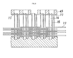
2006-95583 FIG. 7 , while anassembly jig 41 for pins is rotated, each pair ofpins pin insertion recesses 42 formed in theassembly jig 41 with a predetermined pitch. In this way, all thepins chain 1 are arranged on theassembly jig 41 for pins, and held in the same arrangement state as that when thepins chain 1. Then, as shown inFIG. 8 ,links 11 used in thechain 1 are sequentially press-fitted to thesepins jigs 45 such that thelinks 11 are laminated on top of each other in the chain width direction. - Further, a similar assembly jig for pins is described in, for example,
US Patent No. 7140173 . - The aforementioned conventional method of manufacturing a power transmission chain and the aforementioned conventional assembly jig for pins for a power transmission chain may cause the following inconvenience. That is, some pins that are loosely fitted in the assembly jig due to dimensional variations in manufacturing may topple down while the assembly jig for pins rotates. Accordingly, it is preferable to provide a device used to retain the pins. However, it is difficult to provide a retention device in such a manner that the retention device does not hinder press-fitting of the links by the pressing jigs. Therefore, retaining the pins with a compact and simple mechanism is a task that should be accomplished.
- It is an object of the invention to provide an assembly jig for pins for a power transmission chain, which makes it possible to retain pins with a compact and simple mechanism.
- An aspect of the invention relates to an assembly jig for pins, which is used to manufacture a power transmission chain that includes a plurality of links each having front and rear insertion portions through which pins are passed, and a plurality of first pins and a plurality of second pins. Each first pin and a corresponding one of the second pins are aligned next to each other in the longitudinal direction of the links, and the first pins and the second pins connect the links, aligned in the chain width direction, to each other such that the front insertion portion of one link corresponds to the rear insertion portion of another link. The first pins and the second pins move while being in rolling contact with respect to each other, so that the links are flexural with respect to each other in the chain length direction. Thus, the chain is able to shift from the straight state to the curved state. One of the first pin and the second pin is fixed to the front insertion portion of the one link through press-fitting and is movably fitted in the rear insertion portion of the other link, and the other of the first pin and the second pin is movably fitted in the front insertion portion of the one link and is fixed to the rear insertion portion of the other link through press-fitting. The assembly jig includes a jig body in which pin insertion recesses, into which respective pairs of pins are inserted, are aligned at predetermined intervals. The jig body has urging device installation recesses formed so as to be contiguous with the respective pin insertion recesses. In each urging device installation recess, there is arranged an urging device that urges a lower end portion of the pin fitted in the pin insertion recess in the direction perpendicular to the axial direction of the pins.
- The foregoing and further features and advantages of the invention will become apparent from the following description of example embodiments with reference to the accompanying drawings, wherein like numerals are used to represent like elements and wherein:
-
FIG. 1 is a plain view showing part of a power transmission chain that is manufactured with the use of an assembly jig for pins for a power transmission chain according to an embodiment of the invention; -
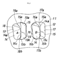
FIG. 2 is an enlarged side view of a link and pins; -
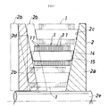
FIG. 3 is a front view showing the state where the power transmission chain is attached to a pulley; -
FIG. 4 is a plain view showing an assembly jig for pins for a power transmission chain according to a first embodiment of the invention; -
FIG. 5 is a vertical sectional view of the assembly jig; -
FIG. 6 is a plain view showing an assembly jig for pins for a power transmission chain according to a second embodiment of the invention; -
FIG. 7 is a perspective view showing a conventional assembly jig for pins; and -
FIG. 8 is a vertical sectional view showing the conventional assembly jig for pins. - Hereafter, embodiments of the invention will be described with reference to the accompanying drawings. In the following description, the up-and-down direction in a power transmission chain signifies the up-and-down direction in
FIG. 2 , and the up-and-down direction in an assembly jig for pins signifies the up-and-down direction inFIG. 5 . -
FIG. 1 shows part of a power transmission chain that is manufactured with the use of an assembly jig for pins for a power transmission chain according to the invention. Apower transmission chain 1 includes a plurality oflinks 11, a plurality of pins (first pins) 14, and a plurality of interpieces (second pins) 15. Eachlink 11 has afront insertion portion 12 and arear insertion portion 13 that are formed at a predetermined interval in the chain length direction.
The pins (first pins) 14 and the interpieces (second pins) 15 connect thelinks 11, aligned in the chain width direction, to each other such that thelinks 11 are flexural with respect to each other in the chain length direction. Thus, thechain 1 is able to shift from the straight state to the curved state. Theinterpiece 15 is shorter than thepin 14. Theinterpiece 15 and thepin 14 face each other such that theinterpiece 15 is arranged in front of thepin 14 in the chain traveling direction. - The
chain 1 is formed by arranging three link rows, each of which is constituted of a plurality of links having the same phase in the chain width direction, in the chain traveling direction (longitudinal direction) to constitute a single link unit, and connecting a plurality of link units, each of which is constituted of the three link rows, to each other in the chain traveling direction. In the present embodiment, one link row having nine links and two link rows each having eight links constitute a single link unit. - As shown in
FIG. 2 , thefront insertion portion 12 of eachlink 11 is formed of a pinmovable portion 16 to which one of thepins 14 is movably fitted, and aninterpiece fixation portion 17 to which one of theinterpieces 15 is fixed. Therear insertion portion 13 is formed of apin fixation portion 18 to which another of thepins 14 is fixed, and an interpiecemovable portion 19 to which another of theinterpieces 15 is movably fitted. - Each
pin 14 is wider in the link longitudinal direction than eachinterpiece 15. Eachinterpiece 15 has, at its upper and lower edges, protrudingedge portions corresponding pin 14. - In connecting the
links 11 aligned in the chain width direction to each other, thelinks 11 are placed on top of each other such that thefront insertion portion 12 of onelink 11 corresponds to therear insertion portion 13 of anotherlink 11. Subsequently, thepin 14 is fixed to therear insertion portion 13 of the onelink 11 and is movably fitted to thefront insertion portion 12 of theother link 11. Subsequently, theinterpiece 15 is movably fitted to therear insertion portion 13 of the onelink 11 and fixed to thefront insertion portion 12 of theother link 11. Then, thepin 14 and theinterpiece 15 move while being in rolling contact with respect to each other, so that thelinks 11 are flexural with respect to each other in the chain length direction (longitudinal direction). Thus, thechain 1 is able to shift from the straight state to the curved state. - At the boundary between the
pin fixation portion 18 and the interpiecemovable portion 19 of eachlink 11, there are formed upper and lower arc-shapedconvex retention portions concave guide portions movable portion 19, respectively, and which retain thepin 14 fixed to thepin fixation portion 18. Similarly, at the boundary between theinterpiece fixation portion 17 and the pinmovable portion 16, there are formed upper and lower arc-shapedconvex retention portions concave guide portions movable portion 16, respectively, and which retain theinterpiece 15 fixed to theinterpiece fixation portion 17. - The locus of a contact position, at which the
pin 14 and theinterpiece 15 contact each other, with respect to thepin 14 is the involute of a circle. In the present embodiment, a rollingcontact surface 14a of thepin 14 is an involute curve having a base circle with a center M and a radius Rb in cross-section, and a rollingcontact surface 15c of theinterpiece 15 is a flat surface (of which the cross-sectional shape is rectilinear). Thus, when each link 11 shifts from a rectilinear region of thechain 1 to a curve region thereof or from the curve region to the rectilinear region, in thefront insertion portion 12, thepin 14 moves within the pinmovable portion 16 with respect to the fixedinterpiece 15 while the rollingcontact surface 14a of thepin 14 is in rolling contact (including slight sliding contact) with the rollingcontact surface 15c of theinterpiece 15. At this time, in therear insertion portion 13, theinterpiece 15 moves within the interpiecemovable portion 19 with respect to the fixedpin 14 while the rollingcontact surface 15c of theinterpiece 15 is in rolling contact (including slight sliding contact) with the rollingcontact surface 14a of thepin 14. - The
power transmission chain 1 is used in a continuously variable transmission (CVT). In this case, as shown inFIG. 3 , end faces of eachpin 14 are in contact with aconical sheave face 2c of a fixedsheave 2a of adrive pulley 2 having apulley shaft 2e and aconical sheave face 2d of amovable sheave 2b of thedrive pulley 2, with end faces of eachinterpiece 15 out of contact with the conical sheave faces 2c and 2d of thedrive pulley 2. Power is transmitted under frictional force resulting from the contact between the end faces of eachpin 14 and the conical sheave faces 2c, 2d. - As shown in
FIG. 3 , if themovable sheave 2b of thedrive pulley 2, which is located at a position indicated by solid lines, is moved toward/away from the fixedsheave 2a, the running diameter of the circle of rotation of thedrive pulley 2 increases as themovable sheave 2b moves toward the fixedsheave 2a, and decreases as themovable sheave 2b moves away from the fixedsheave 2a, as indicated by chain lines. Although not shown in the drawings, a movable sheave of a driven pulley moves toward a fixed sheave as themovable sheave 2b of thedrive pulley 2 moves away from the fixedsheave 2a, and moves away from the fixed shave as themovable sheave 2b moves toward the fixedsheave 2a. As the running diameter of the circle of rotation of thedrive pulley 2 increases, the running diameter of the circle of rotation of the driven pulley decreases. As the running diameter of the circle of rotation of thedrive pulley 2 decreases, the running diameter of the circle of rotation of the driven pulley increases. As a result, the underdrive (U/D) state where the running diameter of the circle of rotation of thedrive pulley 2 is minimized and the running diameter of the circle of rotation of the driven pulley is maximized is obtained, or the overdrive (O/D) state where the running diameter of the circle of rotation of thedrive pulley 2 is maximized and the running diameter of the circle of rotation of the driven pulley is minimized is obtained, using the state where the speed change ratio is 1:1 (initial value) as a reference state. - The
power transmission chain 1 is manufactured by retaining a required number ofpins 14 and a required number ofinterpieces 15, and then sequentially press-fitting a required number oflinks 11 to thepins 14 and theinterpieces 15. Thelinks 11 are press-fitted to thepins 14 and theinterpieces 15 such that the upper and lower edges of thepin 14 are fixed to the upper and lower edges of thepin fixation portion 18, respectively, and the upper and lower edges of theinterpiece 15 are fixed to the upper and lower edges of theinterpiece fixation portion 17, respectively, as shown inFIG. 2 . The press-fitting interference is set to 0.005 mm to 0.1 mm. - A method of manufacturing the power transmission chain is similar to a conventional method, and includes a pin retaining step and a link press-fitting step. In the pin retaining step, all the
pins 14 andinterpieces 15 used in thechain 1 are grouped into multiple pairs each including onepin 14 and oneinterpiece 15, and the multiple pairs ofpin 14 andinterpiece 15 are arranged on an assembly jig 20 (30) for pins with a predetermined pitch (at predetermined intervals) and retained in the same arrangement state as that when thepins 14 and theinterpieces 15 are assembled into thechain 1. In the link press-fitting step, thelinks 11 used in thechain 1 are sequentially press-fitted to thepins 14 and theinterpieces 15 so as to be laminated on top of each other in the chain width direction. - As shown in
FIGS. 7 and8 , aconventional assembly jig 41 for pins is designed to retain thepins 14 and theinterpieces 15 using only frictional forces generated by fitting the lower ends thereof into pin insertion recesses 42. In contrast, urging devices 24 (34) that generate elastic forces are provided in the assembly jig 20 (30) for pins according to the invention, as will be described below. -
FIGS. 4 and5 show theassembly jig 20 for pins for a power transmission chain according to a first embodiment of the invention. As shown inFIGS. 4 and5 , theassembly jig 20 for pins includes ajig body 21 and the urgingdevices 24. In thejig body 21, pin insertion recesses 22, into which the respective pairs each including onepin 14 and oneinterpiece 15 are inserted, are formed at predetermined intervals. The urgingdevice 24 urges the lower end portion of theinterpiece 15 fitted in thepin insertion recess 22 in the direction perpendicular to the axial direction of the interpiece 15 (in the direction parallel to the upper face of theassembly jig 20 for pins). - The
jig body 21 has a circular shape (circular disc-shape). In thejig body 21, urging device installation recesses 23 are formed so as to be contiguous with the respective pin insertion recesses 22 in the direction in which the pin insertions recesses are aligned (in the circumferential direction of the jig body 21). The urgingdevice installation recess 23 is formed next to a portion of thepin insertion recess 22, into which theinterpiece 15 is inserted. The urgingdevice installation recess 23 has an elongated shape with a narrow width, and extends inward in the radial direction of thejig body 21. - Each urging
device 24 may be a leaf spring, and is provided in the urgingdevice installation recess 23 so as to be able to urge theinterpiece 15 in the circumferential direction (the direction in which the pin insertion recesses 22 are aligned) and so as to be deformable in the direction away from theinterpiece 15. - Each
pin insertion recess 22 has a bottom, and the depth thereof coincides with the amount (sticlc-out amount) by which thepin 14 and theinterpiece 15 each stick out of the outermost one of thelinks 11 aligned in the chain width direction. The bottom face of eachpin insertion recess 22 is stepped such that thepin 14 and theinterpiece 15 stick out of theoutermost link 11 by predetermined amounts. The transverse sectional shape of thepin insertion recess 22 is substantially the same as the shape of each of the front andrear insertion portions link 11. Thepin insertion recess 2 is formed such that thepin 14 and theinterpiece 15 are able to be inserted into and removed from thepin insertion recess 22 and the insertedpin 14 andinter-pin 15 are immovable. - The
assembly jig 20 for pins is rotatable about its vertical axis. When thepower transmission chain 1 is manufactured, first of all, thepins 14 and theinterpieces 15 are inserted into the respective pin insertion recesses 22 while theassembly jig 20 for pins is rotated. Subsequently, thelinks 11 are arranged at upper ends of thepins 14 and theinterpieces 15 by a link supply device (not shown). Subsequently, link pressing jigs (seeFIG. 8 ) are lowered to move thelinks 11 to predetermined positions. After that, rotation of theassembly jig 20 for pins by a predetermined amount, arrangement of thelinks 11, and lowering of the link pressing jigs are repeated to assemble thepower transmission chain 1. - As described above, the transverse sectional shape of the
pin insertion recess 22 is designed such that the insertedpin 14 andinterpiece 15 are immovable. However, somepins 14 andinterpieces 15 that are loosely fitted in theassembly jig 20 due to dimensional variations in manufacturing may topple down while theassembly jig 20 for pins rotates. - In the
assembly jig 20 for pins according to the first embodiment, the lower end portion of one of the pairedpin 14 and interpiece 15 (interpiece 15, in the first embodiment) is pressed by theleaf spring 24 that serves as the urging device in such a direction as to press the other one of the pairedpin 14 and the interpiece 15(pin 14, in the first embodiment). The lower end portion of thepin 14 is pressed to the peripheral face of thepin insertion recess 22, so that the lower end portions of both thepin 14 and theinterpiece 15 are retained within thepin insertion recess 22. Thus, thepin 14 and theinterpiece 15 no longer topple down. Theleaf spring 24 is provided in the urgingdevice installation recess 23, and therefore does not stick out of the upper face of thejig body 21, that is, does not hinder press-fitting of thelinks 11, which is performed using pressing jigs in a link press-fitting step. The interval between the consecutive pin insertion recesses 22 is determined based on the dimension of thepower transmission chain 1. Therefore, it is difficult to ensure a sufficient space for installation of the urging device. However, using the leaf spring as the urgingdevice 24 makes it possible to install the urgingdevice 24 in a small space. In this manner, thepins 14 and theinterpieces 15 are retained with a compact and simple mechanism. -
FIG. 6 shows anassembly jig 30 for pins for a power transmission chain according to a second embodiment of the invention. As shown inFIG. 6 , theassembly jig 30 for pins according to the second embodiment includes ajig body 31 and urgingdevices 34. In thejig body 31,pin insertion recesses pin 14 and oneinterpiece 15 are inserted, are formed at predetermined intervals. Each urgingdevice 34 urges the lower end portions of both thepin 14 fitted in thepin insertion recess 32B and theinterpiece 15 fitted in thepin insertion recess 32A, in the direction perpendicular to the axial direction of thepin 14 and the interpiece 15 (the direction parallel to the upper face of theassembly jig 30 for pins). - The
jig body 31 has a circular shape (circular disc-shape). In thejig body 31, urging device installation recesses 33 are formed between the consecutivepin insertion recesses device installation recess 33 is contiguous with radially inward portions of thepin insertion recesses device 34 is provided in the urgingdevice installation recess 33, and has ahelical compression spring 35 of which the urging direction is the radially outward direction (the direction perpendicular to the direction in which the urging device installation recesses 33 are aligned), and a pressingmember 36 urged by thehelical compression spring 35. - The pressing
member 36 has a firstpressing face 36a and a secondpressing face 36b. The firstpressing face 36a contacts the pin (the pin which is located in thepin insertion recess 32A, at a position close to thepin insertion recess 32B) 14 at a predetermined angle with respect to the direction in which the urging device installation recesses 33 are aligned. The secondpressing face 36b contacts the interpiece (the pin which is located in thepin insertion recess 32B, at a position close to thepin insertion recess 32A) 15 at a predetermined angle with respect to the direction in which the urging device installation recesses 33 are aligned. - Within the urging
device installation recess 33, the pressingmember 36 is not only movable in the radial direction (the direction in which thehelical compression spring 35 urges pressing member 26), but also movable in the circumferential direction (the direction perpendicular to the direction in which thehelical compression spring 35 urges the pressing member 26) due to a clearance C formed between the pressingmember 36 and the peripheral face of the urgingdevice installation recess 33 in the circumferential direction. - With this structure, all the
pins 14 andinterpieces 15 are urged by elastic forces of the helical compression springs 35 via thepressing members 36, respectively. Thus, thepins 14 and theinterpieces 15 are reliably prevented from toppling down. - The urging
device 34 is provided in the urgingdevice installation recess 33, and therefore does not stick out of the upper face of thejig body 31, that is, does not hinder press-fitting of thelinks 11 that is performed with the use of the pressing jigs in the link press-fitting step. The interval between the consecutivepin insertion recesses power transmission chain 1. Therefore, it is difficult to ensure a sufficient space for installation of the urging device. However, the urgingdevice 34 is located radially inward of thepin insertion recesses pin 14 and theinterpiece 15 are simultaneously pressed by the singlehelical compression spring 35 via the pressingmember 36. Therefore, the urgingdevice 34 is installed in a small space. In this manner, thepins 14 and theinterpieces 15 are retained with a compact and simple mechanism. - The aforementioned assembly jigs 20 and 30 for pins are not limited by the shapes of the links, the pins, or the interpieces, but may be applicable to various power transmission chains.
- Each link may be made of, for example, spring steel or carbon tool steel. However, the material of the link is not limited to spring steel or carbon tool steel, but the link may be made of another steel such as bearing steel. The front and rear insertion portions of each link may be through-holes that are separated from each other (each link may have a column portion), or may be a single through-hole (each link may have no column portion). Steel such as bearing steel may be used as the material of the pins. The assembly jig for pins may be made of, for example, carbon tool steel, or alloy tool steel.
- In the assembly jig for pins for a power transmission chain according to the invention, the jig body has the urging device installation recesses that are contiguous with the respective pin insertion recesses, and the urging device that urges the lower end portion of the pin fitted in the pin insertion recess, in the direction perpendicular to the axial direction of the pin, is provided in the urging device installation recess. Therefore, the urging device does not hinder press-fitting of the links. As a result, it is possible to retain the pins with a compact and simple mechanism.
Claims (3)
- An assembly jig for pins, which is used to manufacture a power transmission chain that includes a plurality of links each having front and rear insertion portions through which pins are passed, and a plurality of first pins and a plurality of second pins, wherein each first pin and a corresponding one of the second pins are aligned next to each other in a longitudinal direction of the links, and the first pins and the second pins connect the links, aligned in a chain width direction, to each other such that the front insertion portion of one link corresponds to the rear insertion portion of another link, wherein the first pins and the second pins move while being in rolling contact with respect to each other, so that the links are flexural with respect to each other in a chain length direction, and wherein one of the first pin and the second pin is fixed to the front insertion portion of the one link through press-fitting and is movably fitted in the rear insertion portion of the other link, and the other of the first pin and the second pin is movably fitted in the front insertion portion of the one link and is fixed to the rear insertion portion of the other link through press-fitting,
the assembly jig comprising
a jig body in which pin insertion recesses, into which respective pairs of pins are inserted, are aligned at predetermined intervals,
the assembly jig characterized in that:the jig body has urging device installation recesses formed so as to be contiguous with the respective pin insertion recesses; andin each urging device installation recess, there is arranged an urging device that urges a lower end portion of the pin fitted in the pin insertion recess in a direction perpendicular to an axial direction of the pins. - The assembly jig for pins for a power transmission chain according to claim 1:wherein the urging device installation recesses are formed so as to be contiguous with the respective pin insertion recesses in a direction in which the pin insertion recesses are aligned; andwherein each urging device is a leaf spring of which an urging direction coincides with the direction in which the pin insertion recesses are aligned.
- The assembly jig for pins for a power transmission chain according to claim 1:wherein each urging device installation recess is formed between the consecutive pin insertion recesses so as to be contiguous with the consecutive pin insertion recesses;wherein each urging device includes a coil spring of which an urging direction is perpendicular to the direction in which the pin insertion recesses are aligned, and a pressing member that is urged by the coil spring; andwherein the pressing member has a first pressing face that contacts the pin which is located in one of the consecutive pin insertion recesses, on a side close to the other pin insertion recess, at a predetermined angle with respect to the direction in which the pin insertion recesses are aligned, and a second pressing face that contacts the pin which is located in the other pin insertion recess, on a side close to the one of the consecutive pin insertion recesses, at a predetermined angle with respect to the direction in which the pin insertion recesses are aligned.
Applications Claiming Priority (1)
| Application Number | Priority Date | Filing Date | Title |
|---|---|---|---|
| JP2010275226A JP5625851B2 (en) | 2010-12-10 | 2010-12-10 | Power transmission chain pin assembly jig |
Publications (2)
| Publication Number | Publication Date |
|---|---|
| EP2463042A1 true EP2463042A1 (en) | 2012-06-13 |
| EP2463042B1 EP2463042B1 (en) | 2013-08-07 |
Family
ID=45218417
Family Applications (1)
| Application Number | Title | Priority Date | Filing Date |
|---|---|---|---|
| EP11192515.2A Not-in-force EP2463042B1 (en) | 2010-12-10 | 2011-12-08 | Assembly jig for pins for power transmission chain |
Country Status (4)
| Country | Link |
|---|---|
| US (1) | US9199302B2 (en) |
| EP (1) | EP2463042B1 (en) |
| JP (1) | JP5625851B2 (en) |
| CN (1) | CN102527917B (en) |
Cited By (1)
| Publication number | Priority date | Publication date | Assignee | Title |
|---|---|---|---|---|
| CN109731996A (en) * | 2019-01-31 | 2019-05-10 | 深圳市金玲珑珠宝首饰有限公司 | A kind of full-automatic split-mounting type necklace mold |
Families Citing this family (4)
| Publication number | Priority date | Publication date | Assignee | Title |
|---|---|---|---|---|
| JP5625851B2 (en) * | 2010-12-10 | 2014-11-19 | 株式会社ジェイテクト | Power transmission chain pin assembly jig |
| US10451393B2 (en) * | 2015-06-29 | 2019-10-22 | Bohning Company, Ltd | Arrow fletching device with plate clamp |
| CN107478429A (en) * | 2017-09-22 | 2017-12-15 | 苏州顺革智能科技有限公司 | A kind of detection device for chain assembling |
| CN112045588B (en) * | 2020-08-13 | 2024-03-22 | 山西柴油机工业有限责任公司 | Universal tool |
Citations (6)
| Publication number | Priority date | Publication date | Assignee | Title |
|---|---|---|---|---|
| GB1261282A (en) * | 1968-02-28 | 1972-01-26 | Massey Ferguson Gmbh | Apparatus for and method of assembling roller-chain links |
| JP2006095583A (en) | 2004-09-30 | 2006-04-13 | Jtekt Corp | Power transmission chain manufacturing method and pin retainer |
| JP2006095531A (en) * | 2004-09-28 | 2006-04-13 | Jtekt Corp | Power transmission chain manufacturing method and power transmission chain manufacturing apparatus used therefor |
| US7140173B2 (en) | 2004-03-04 | 2006-11-28 | Gear Chain Industrial B.V. | Method and device for assembling an endless chain, in particular a transmission chain |
| EP1952907A1 (en) * | 2007-02-01 | 2008-08-06 | JTEKT Corporation | Method of producing power transmission chain and press-fitting apparatus used in said method |
| JP2009119507A (en) * | 2007-11-16 | 2009-06-04 | Jtekt Corp | Power transmission chain pin assembly jig |
Family Cites Families (12)
| Publication number | Priority date | Publication date | Assignee | Title |
|---|---|---|---|---|
| US4794687A (en) * | 1985-10-16 | 1989-01-03 | The Boeing Company | Fixture system for workpiece machining |
| DE19654385C1 (en) * | 1996-12-24 | 1998-08-06 | Theo Fuchs | Firing trays for the dental laboratory |
| EP1579933B1 (en) * | 2004-03-26 | 2006-07-12 | Gear Chain Industrial B.V. | Method and set-up for assembling an endless chain, in particular a transmission chain |
| WO2006049317A1 (en) * | 2004-11-04 | 2006-05-11 | Showa Denko K.K. | Capacitor manufacturing jig, capacitor manufacturing device, and capacitor manufacturing method |
| ITBO20050376A1 (en) * | 2005-05-31 | 2006-12-01 | Jobs Spa | SUPPORT DEVICE FOR COMMITTING OEZZI IN PRODUCTION |
| US7441396B2 (en) | 2005-09-30 | 2008-10-28 | Jtekt Corporation | Manufacture method of power transmission chain and pin-retainer jig |
| KR101320106B1 (en) * | 2006-12-29 | 2013-10-18 | 엘지디스플레이 주식회사 | Glass surport pin, and carrier surface plate |
| JP2008188597A (en) * | 2007-02-01 | 2008-08-21 | Jtekt Corp | Power transmission chain manufacturing method and press-fitting device used therefor |
| JP2009103156A (en) * | 2007-10-22 | 2009-05-14 | Jtekt Corp | Power transmission chain assembly jig and assembly method |
| JP5446091B2 (en) * | 2007-12-25 | 2014-03-19 | 株式会社ジェイテクト | Press-fitting method and press-fitting device for link and pin of power transmission chain |
| JP2009255121A (en) * | 2008-04-16 | 2009-11-05 | Jtekt Corp | Pre-tensioning method and apparatus for power transmission chain |
| JP5625851B2 (en) * | 2010-12-10 | 2014-11-19 | 株式会社ジェイテクト | Power transmission chain pin assembly jig |
-
2010
- 2010-12-10 JP JP2010275226A patent/JP5625851B2/en not_active Expired - Fee Related
-
2011
- 2011-12-07 US US13/313,280 patent/US9199302B2/en not_active Expired - Fee Related
- 2011-12-08 EP EP11192515.2A patent/EP2463042B1/en not_active Not-in-force
- 2011-12-08 CN CN201110405323.5A patent/CN102527917B/en not_active Expired - Fee Related
Patent Citations (6)
| Publication number | Priority date | Publication date | Assignee | Title |
|---|---|---|---|---|
| GB1261282A (en) * | 1968-02-28 | 1972-01-26 | Massey Ferguson Gmbh | Apparatus for and method of assembling roller-chain links |
| US7140173B2 (en) | 2004-03-04 | 2006-11-28 | Gear Chain Industrial B.V. | Method and device for assembling an endless chain, in particular a transmission chain |
| JP2006095531A (en) * | 2004-09-28 | 2006-04-13 | Jtekt Corp | Power transmission chain manufacturing method and power transmission chain manufacturing apparatus used therefor |
| JP2006095583A (en) | 2004-09-30 | 2006-04-13 | Jtekt Corp | Power transmission chain manufacturing method and pin retainer |
| EP1952907A1 (en) * | 2007-02-01 | 2008-08-06 | JTEKT Corporation | Method of producing power transmission chain and press-fitting apparatus used in said method |
| JP2009119507A (en) * | 2007-11-16 | 2009-06-04 | Jtekt Corp | Power transmission chain pin assembly jig |
Cited By (2)
| Publication number | Priority date | Publication date | Assignee | Title |
|---|---|---|---|---|
| CN109731996A (en) * | 2019-01-31 | 2019-05-10 | 深圳市金玲珑珠宝首饰有限公司 | A kind of full-automatic split-mounting type necklace mold |
| CN109731996B (en) * | 2019-01-31 | 2024-04-16 | 深圳市金玲珑珠宝首饰有限公司 | Full-automatic assembled combined necklace die |
Also Published As
| Publication number | Publication date |
|---|---|
| JP5625851B2 (en) | 2014-11-19 |
| US9199302B2 (en) | 2015-12-01 |
| JP2012121057A (en) | 2012-06-28 |
| CN102527917A (en) | 2012-07-04 |
| EP2463042B1 (en) | 2013-08-07 |
| CN102527917B (en) | 2015-07-01 |
| US20120146278A1 (en) | 2012-06-14 |
Similar Documents
| Publication | Publication Date | Title |
|---|---|---|
| EP2463042B1 (en) | Assembly jig for pins for power transmission chain | |
| EP1952907B1 (en) | Method of producing power transmission chain and press-fitting apparatus used in said method | |
| EP2053270B1 (en) | Power transmission chain and power transmission apparatus | |
| JP2008188597A (en) | Power transmission chain manufacturing method and press-fitting device used therefor | |
| JP4910982B2 (en) | Manufacturing method of power transmission chain | |
| EP1953413B1 (en) | Power transmission chain and power transmission apparatus | |
| JP2009103156A (en) | Power transmission chain assembly jig and assembly method | |
| JP4946462B2 (en) | Power transmission device | |
| EP1801454B1 (en) | Power transmission chain, method for manufacturing the same, and power transmission apparatus | |
| EP1985890A2 (en) | Power transmitting chain and power transmitting apparatus | |
| JP2009154164A (en) | Power transmission chain manufacturing method and manufacturing apparatus | |
| JP2009119507A (en) | Power transmission chain pin assembly jig | |
| JP5532788B2 (en) | Power transmission device | |
| JP2008144825A (en) | Power transmission chain and power transmission device | |
| JP4893562B2 (en) | Power transmission chain and power transmission device | |
| JP2009074671A (en) | Power transmission device and power transmission chain | |
| JP2009222106A (en) | Power transmission chain and power transmission device | |
| JP2008208920A (en) | Power transmission chain and power transmission device | |
| JP2008215448A (en) | Power transmission chain and power transmission device | |
| JP2008180296A (en) | Power transmission chain and power transmission device | |
| JP2009079639A (en) | Power transmission chain and power transmission device | |
| JP2008169879A (en) | Power transmission chain and power transmission device | |
| JP2011200874A (en) | Method for manufacturing power transmission chain | |
| JP2008144826A (en) | Power transmission chain and power transmission device | |
| JP2011069413A (en) | Power transmission chain and power transmission device |
Legal Events
| Date | Code | Title | Description |
|---|---|---|---|
| PUAI | Public reference made under article 153(3) epc to a published international application that has entered the european phase |
Free format text: ORIGINAL CODE: 0009012 |
|
| AK | Designated contracting states |
Kind code of ref document: A1 Designated state(s): AL AT BE BG CH CY CZ DE DK EE ES FI FR GB GR HR HU IE IS IT LI LT LU LV MC MK MT NL NO PL PT RO RS SE SI SK SM TR |
|
| AX | Request for extension of the european patent |
Extension state: BA ME |
|
| 17P | Request for examination filed |
Effective date: 20121206 |
|
| GRAP | Despatch of communication of intention to grant a patent |
Free format text: ORIGINAL CODE: EPIDOSNIGR1 |
|
| GRAS | Grant fee paid |
Free format text: ORIGINAL CODE: EPIDOSNIGR3 |
|
| GRAA | (expected) grant |
Free format text: ORIGINAL CODE: 0009210 |
|
| AK | Designated contracting states |
Kind code of ref document: B1 Designated state(s): AL AT BE BG CH CY CZ DE DK EE ES FI FR GB GR HR HU IE IS IT LI LT LU LV MC MK MT NL NO PL PT RO RS SE SI SK SM TR |
|
| REG | Reference to a national code |
Ref country code: GB Ref legal event code: FG4D |
|
| REG | Reference to a national code |
Ref country code: AT Ref legal event code: REF Ref document number: 625519 Country of ref document: AT Kind code of ref document: T Effective date: 20130815 Ref country code: CH Ref legal event code: EP |
|
| REG | Reference to a national code |
Ref country code: IE Ref legal event code: FG4D |
|
| REG | Reference to a national code |
Ref country code: DE Ref legal event code: R096 Ref document number: 602011002608 Country of ref document: DE Effective date: 20131002 |
|
| REG | Reference to a national code |
Ref country code: AT Ref legal event code: MK05 Ref document number: 625519 Country of ref document: AT Kind code of ref document: T Effective date: 20130807 |
|
| REG | Reference to a national code |
Ref country code: NL Ref legal event code: VDEP Effective date: 20130807 |
|
| REG | Reference to a national code |
Ref country code: LT Ref legal event code: MG4D |
|
| PG25 | Lapsed in a contracting state [announced via postgrant information from national office to epo] |
Ref country code: AT Free format text: LAPSE BECAUSE OF FAILURE TO SUBMIT A TRANSLATION OF THE DESCRIPTION OR TO PAY THE FEE WITHIN THE PRESCRIBED TIME-LIMIT Effective date: 20130807 Ref country code: LT Free format text: LAPSE BECAUSE OF FAILURE TO SUBMIT A TRANSLATION OF THE DESCRIPTION OR TO PAY THE FEE WITHIN THE PRESCRIBED TIME-LIMIT Effective date: 20130807 Ref country code: PT Free format text: LAPSE BECAUSE OF FAILURE TO SUBMIT A TRANSLATION OF THE DESCRIPTION OR TO PAY THE FEE WITHIN THE PRESCRIBED TIME-LIMIT Effective date: 20131209 Ref country code: HR Free format text: LAPSE BECAUSE OF FAILURE TO SUBMIT A TRANSLATION OF THE DESCRIPTION OR TO PAY THE FEE WITHIN THE PRESCRIBED TIME-LIMIT Effective date: 20130807 Ref country code: CY Free format text: LAPSE BECAUSE OF FAILURE TO SUBMIT A TRANSLATION OF THE DESCRIPTION OR TO PAY THE FEE WITHIN THE PRESCRIBED TIME-LIMIT Effective date: 20130828 Ref country code: IS Free format text: LAPSE BECAUSE OF FAILURE TO SUBMIT A TRANSLATION OF THE DESCRIPTION OR TO PAY THE FEE WITHIN THE PRESCRIBED TIME-LIMIT Effective date: 20131207 Ref country code: SE Free format text: LAPSE BECAUSE OF FAILURE TO SUBMIT A TRANSLATION OF THE DESCRIPTION OR TO PAY THE FEE WITHIN THE PRESCRIBED TIME-LIMIT Effective date: 20130807 Ref country code: NO Free format text: LAPSE BECAUSE OF FAILURE TO SUBMIT A TRANSLATION OF THE DESCRIPTION OR TO PAY THE FEE WITHIN THE PRESCRIBED TIME-LIMIT Effective date: 20131107 |
|
| PG25 | Lapsed in a contracting state [announced via postgrant information from national office to epo] |
Ref country code: GR Free format text: LAPSE BECAUSE OF FAILURE TO SUBMIT A TRANSLATION OF THE DESCRIPTION OR TO PAY THE FEE WITHIN THE PRESCRIBED TIME-LIMIT Effective date: 20131108 Ref country code: LV Free format text: LAPSE BECAUSE OF FAILURE TO SUBMIT A TRANSLATION OF THE DESCRIPTION OR TO PAY THE FEE WITHIN THE PRESCRIBED TIME-LIMIT Effective date: 20130807 Ref country code: FI Free format text: LAPSE BECAUSE OF FAILURE TO SUBMIT A TRANSLATION OF THE DESCRIPTION OR TO PAY THE FEE WITHIN THE PRESCRIBED TIME-LIMIT Effective date: 20130807 Ref country code: NL Free format text: LAPSE BECAUSE OF FAILURE TO SUBMIT A TRANSLATION OF THE DESCRIPTION OR TO PAY THE FEE WITHIN THE PRESCRIBED TIME-LIMIT Effective date: 20130807 Ref country code: PL Free format text: LAPSE BECAUSE OF FAILURE TO SUBMIT A TRANSLATION OF THE DESCRIPTION OR TO PAY THE FEE WITHIN THE PRESCRIBED TIME-LIMIT Effective date: 20130807 Ref country code: BE Free format text: LAPSE BECAUSE OF FAILURE TO SUBMIT A TRANSLATION OF THE DESCRIPTION OR TO PAY THE FEE WITHIN THE PRESCRIBED TIME-LIMIT Effective date: 20130807 Ref country code: SI Free format text: LAPSE BECAUSE OF FAILURE TO SUBMIT A TRANSLATION OF THE DESCRIPTION OR TO PAY THE FEE WITHIN THE PRESCRIBED TIME-LIMIT Effective date: 20130807 |
|
| PG25 | Lapsed in a contracting state [announced via postgrant information from national office to epo] |
Ref country code: CY Free format text: LAPSE BECAUSE OF FAILURE TO SUBMIT A TRANSLATION OF THE DESCRIPTION OR TO PAY THE FEE WITHIN THE PRESCRIBED TIME-LIMIT Effective date: 20130807 |
|
| PG25 | Lapsed in a contracting state [announced via postgrant information from national office to epo] |
Ref country code: DK Free format text: LAPSE BECAUSE OF FAILURE TO SUBMIT A TRANSLATION OF THE DESCRIPTION OR TO PAY THE FEE WITHIN THE PRESCRIBED TIME-LIMIT Effective date: 20130807 Ref country code: CZ Free format text: LAPSE BECAUSE OF FAILURE TO SUBMIT A TRANSLATION OF THE DESCRIPTION OR TO PAY THE FEE WITHIN THE PRESCRIBED TIME-LIMIT Effective date: 20130807 Ref country code: RO Free format text: LAPSE BECAUSE OF FAILURE TO SUBMIT A TRANSLATION OF THE DESCRIPTION OR TO PAY THE FEE WITHIN THE PRESCRIBED TIME-LIMIT Effective date: 20130807 Ref country code: EE Free format text: LAPSE BECAUSE OF FAILURE TO SUBMIT A TRANSLATION OF THE DESCRIPTION OR TO PAY THE FEE WITHIN THE PRESCRIBED TIME-LIMIT Effective date: 20130807 Ref country code: SK Free format text: LAPSE BECAUSE OF FAILURE TO SUBMIT A TRANSLATION OF THE DESCRIPTION OR TO PAY THE FEE WITHIN THE PRESCRIBED TIME-LIMIT Effective date: 20130807 |
|
| PG25 | Lapsed in a contracting state [announced via postgrant information from national office to epo] |
Ref country code: IT Free format text: LAPSE BECAUSE OF FAILURE TO SUBMIT A TRANSLATION OF THE DESCRIPTION OR TO PAY THE FEE WITHIN THE PRESCRIBED TIME-LIMIT Effective date: 20130807 Ref country code: ES Free format text: LAPSE BECAUSE OF FAILURE TO SUBMIT A TRANSLATION OF THE DESCRIPTION OR TO PAY THE FEE WITHIN THE PRESCRIBED TIME-LIMIT Effective date: 20130807 |
|
| PLBE | No opposition filed within time limit |
Free format text: ORIGINAL CODE: 0009261 |
|
| STAA | Information on the status of an ep patent application or granted ep patent |
Free format text: STATUS: NO OPPOSITION FILED WITHIN TIME LIMIT |
|
| 26N | No opposition filed |
Effective date: 20140508 |
|
| REG | Reference to a national code |
Ref country code: DE Ref legal event code: R097 Ref document number: 602011002608 Country of ref document: DE Effective date: 20140508 |
|
| PG25 | Lapsed in a contracting state [announced via postgrant information from national office to epo] |
Ref country code: LU Free format text: LAPSE BECAUSE OF FAILURE TO SUBMIT A TRANSLATION OF THE DESCRIPTION OR TO PAY THE FEE WITHIN THE PRESCRIBED TIME-LIMIT Effective date: 20131208 |
|
| REG | Reference to a national code |
Ref country code: IE Ref legal event code: MM4A |
|
| PG25 | Lapsed in a contracting state [announced via postgrant information from national office to epo] |
Ref country code: IE Free format text: LAPSE BECAUSE OF NON-PAYMENT OF DUE FEES Effective date: 20131208 |
|
| PG25 | Lapsed in a contracting state [announced via postgrant information from national office to epo] |
Ref country code: MC Free format text: LAPSE BECAUSE OF FAILURE TO SUBMIT A TRANSLATION OF THE DESCRIPTION OR TO PAY THE FEE WITHIN THE PRESCRIBED TIME-LIMIT Effective date: 20130807 |
|
| PG25 | Lapsed in a contracting state [announced via postgrant information from national office to epo] |
Ref country code: SM Free format text: LAPSE BECAUSE OF FAILURE TO SUBMIT A TRANSLATION OF THE DESCRIPTION OR TO PAY THE FEE WITHIN THE PRESCRIBED TIME-LIMIT Effective date: 20130807 |
|
| PG25 | Lapsed in a contracting state [announced via postgrant information from national office to epo] |
Ref country code: TR Free format text: LAPSE BECAUSE OF FAILURE TO SUBMIT A TRANSLATION OF THE DESCRIPTION OR TO PAY THE FEE WITHIN THE PRESCRIBED TIME-LIMIT Effective date: 20130807 |
|
| PG25 | Lapsed in a contracting state [announced via postgrant information from national office to epo] |
Ref country code: HU Free format text: LAPSE BECAUSE OF FAILURE TO SUBMIT A TRANSLATION OF THE DESCRIPTION OR TO PAY THE FEE WITHIN THE PRESCRIBED TIME-LIMIT; INVALID AB INITIO Effective date: 20111208 Ref country code: MK Free format text: LAPSE BECAUSE OF FAILURE TO SUBMIT A TRANSLATION OF THE DESCRIPTION OR TO PAY THE FEE WITHIN THE PRESCRIBED TIME-LIMIT Effective date: 20130807 Ref country code: BG Free format text: LAPSE BECAUSE OF FAILURE TO SUBMIT A TRANSLATION OF THE DESCRIPTION OR TO PAY THE FEE WITHIN THE PRESCRIBED TIME-LIMIT Effective date: 20130807 Ref country code: RS Free format text: LAPSE BECAUSE OF FAILURE TO SUBMIT A TRANSLATION OF THE DESCRIPTION OR TO PAY THE FEE WITHIN THE PRESCRIBED TIME-LIMIT Effective date: 20131107 |
|
| REG | Reference to a national code |
Ref country code: CH Ref legal event code: PL |
|
| PG25 | Lapsed in a contracting state [announced via postgrant information from national office to epo] |
Ref country code: MT Free format text: LAPSE BECAUSE OF FAILURE TO SUBMIT A TRANSLATION OF THE DESCRIPTION OR TO PAY THE FEE WITHIN THE PRESCRIBED TIME-LIMIT Effective date: 20130807 |
|
| PG25 | Lapsed in a contracting state [announced via postgrant information from national office to epo] |
Ref country code: LI Free format text: LAPSE BECAUSE OF NON-PAYMENT OF DUE FEES Effective date: 20141231 Ref country code: CH Free format text: LAPSE BECAUSE OF NON-PAYMENT OF DUE FEES Effective date: 20141231 |
|
| REG | Reference to a national code |
Ref country code: FR Ref legal event code: PLFP Year of fee payment: 5 |
|
| GBPC | Gb: european patent ceased through non-payment of renewal fee |
Effective date: 20151208 |
|
| PG25 | Lapsed in a contracting state [announced via postgrant information from national office to epo] |
Ref country code: GB Free format text: LAPSE BECAUSE OF NON-PAYMENT OF DUE FEES Effective date: 20151208 |
|
| REG | Reference to a national code |
Ref country code: FR Ref legal event code: PLFP Year of fee payment: 6 |
|
| REG | Reference to a national code |
Ref country code: FR Ref legal event code: PLFP Year of fee payment: 7 |
|
| PG25 | Lapsed in a contracting state [announced via postgrant information from national office to epo] |
Ref country code: AL Free format text: LAPSE BECAUSE OF FAILURE TO SUBMIT A TRANSLATION OF THE DESCRIPTION OR TO PAY THE FEE WITHIN THE PRESCRIBED TIME-LIMIT Effective date: 20130807 |
|
| PGFP | Annual fee paid to national office [announced via postgrant information from national office to epo] |
Ref country code: DE Payment date: 20191126 Year of fee payment: 9 |
|
| PGFP | Annual fee paid to national office [announced via postgrant information from national office to epo] |
Ref country code: FR Payment date: 20191115 Year of fee payment: 9 |
|
| REG | Reference to a national code |
Ref country code: DE Ref legal event code: R119 Ref document number: 602011002608 Country of ref document: DE |
|
| PG25 | Lapsed in a contracting state [announced via postgrant information from national office to epo] |
Ref country code: FR Free format text: LAPSE BECAUSE OF NON-PAYMENT OF DUE FEES Effective date: 20201231 |
|
| PG25 | Lapsed in a contracting state [announced via postgrant information from national office to epo] |
Ref country code: DE Free format text: LAPSE BECAUSE OF NON-PAYMENT OF DUE FEES Effective date: 20210701 |