EP2462970B1 - Unité d'aiguille pour injecteur de type stylo avec canules distale et proximale de calibre différent - Google Patents
Unité d'aiguille pour injecteur de type stylo avec canules distale et proximale de calibre différent Download PDFInfo
- Publication number
- EP2462970B1 EP2462970B1 EP11191748.0A EP11191748A EP2462970B1 EP 2462970 B1 EP2462970 B1 EP 2462970B1 EP 11191748 A EP11191748 A EP 11191748A EP 2462970 B1 EP2462970 B1 EP 2462970B1
- Authority
- EP
- European Patent Office
- Prior art keywords
- needle cannula
- needle
- gauge
- transverse wall
- pen
- Prior art date
- Legal status (The legal status is an assumption and is not a legal conclusion. Google has not performed a legal analysis and makes no representation as to the accuracy of the status listed.)
- Active
Links
- 241001631457 Cannula Species 0.000 title description 9
- 238000004891 communication Methods 0.000 claims description 7
- 238000003780 insertion Methods 0.000 claims description 6
- 230000037431 insertion Effects 0.000 claims description 6
- 238000007789 sealing Methods 0.000 claims description 6
- 239000003814 drug Substances 0.000 description 13
- 238000002347 injection Methods 0.000 description 13
- 239000007924 injection Substances 0.000 description 13
- 229940079593 drug Drugs 0.000 description 12
- 239000000853 adhesive Substances 0.000 description 4
- 230000001070 adhesive effect Effects 0.000 description 4
- 230000000712 assembly Effects 0.000 description 4
- 238000000429 assembly Methods 0.000 description 4
- 238000000034 method Methods 0.000 description 3
- 239000003708 ampul Substances 0.000 description 2
- 230000000694 effects Effects 0.000 description 2
- 239000012812 sealant material Substances 0.000 description 2
- 238000010276 construction Methods 0.000 description 1
- 230000004927 fusion Effects 0.000 description 1
- 239000007788 liquid Substances 0.000 description 1
- 239000000463 material Substances 0.000 description 1
- 238000000465 moulding Methods 0.000 description 1
- 238000004513 sizing Methods 0.000 description 1
- 125000006850 spacer group Chemical group 0.000 description 1
- 229920001169 thermoplastic Polymers 0.000 description 1
- 239000004416 thermosoftening plastic Substances 0.000 description 1
Images

Classifications
-
- A—HUMAN NECESSITIES
- A61—MEDICAL OR VETERINARY SCIENCE; HYGIENE
- A61M—DEVICES FOR INTRODUCING MEDIA INTO, OR ONTO, THE BODY; DEVICES FOR TRANSDUCING BODY MEDIA OR FOR TAKING MEDIA FROM THE BODY; DEVICES FOR PRODUCING OR ENDING SLEEP OR STUPOR
- A61M5/00—Devices for bringing media into the body in a subcutaneous, intra-vascular or intramuscular way; Accessories therefor, e.g. filling or cleaning devices, arm-rests
- A61M5/178—Syringes
- A61M5/31—Details
- A61M5/32—Needles; Details of needles pertaining to their connection with syringe or hub; Accessories for bringing the needle into, or holding the needle on, the body; Devices for protection of needles
- A61M5/329—Needles; Details of needles pertaining to their connection with syringe or hub; Accessories for bringing the needle into, or holding the needle on, the body; Devices for protection of needles characterised by features of the needle shaft
-
- A—HUMAN NECESSITIES
- A61—MEDICAL OR VETERINARY SCIENCE; HYGIENE
- A61M—DEVICES FOR INTRODUCING MEDIA INTO, OR ONTO, THE BODY; DEVICES FOR TRANSDUCING BODY MEDIA OR FOR TAKING MEDIA FROM THE BODY; DEVICES FOR PRODUCING OR ENDING SLEEP OR STUPOR
- A61M5/00—Devices for bringing media into the body in a subcutaneous, intra-vascular or intramuscular way; Accessories therefor, e.g. filling or cleaning devices, arm-rests
- A61M5/178—Syringes
- A61M5/31—Details
- A61M5/32—Needles; Details of needles pertaining to their connection with syringe or hub; Accessories for bringing the needle into, or holding the needle on, the body; Devices for protection of needles
- A61M5/3293—Needles; Details of needles pertaining to their connection with syringe or hub; Accessories for bringing the needle into, or holding the needle on, the body; Devices for protection of needles characterised by features of the needle hub
-
- A—HUMAN NECESSITIES
- A61—MEDICAL OR VETERINARY SCIENCE; HYGIENE
- A61M—DEVICES FOR INTRODUCING MEDIA INTO, OR ONTO, THE BODY; DEVICES FOR TRANSDUCING BODY MEDIA OR FOR TAKING MEDIA FROM THE BODY; DEVICES FOR PRODUCING OR ENDING SLEEP OR STUPOR
- A61M5/00—Devices for bringing media into the body in a subcutaneous, intra-vascular or intramuscular way; Accessories therefor, e.g. filling or cleaning devices, arm-rests
- A61M5/178—Syringes
- A61M5/31—Details
- A61M5/32—Needles; Details of needles pertaining to their connection with syringe or hub; Accessories for bringing the needle into, or holding the needle on, the body; Devices for protection of needles
- A61M2005/3201—Coaxially assembled needle cannulas placed on top of another, e.g. needles having different diameters
-
- A—HUMAN NECESSITIES
- A61—MEDICAL OR VETERINARY SCIENCE; HYGIENE
- A61M—DEVICES FOR INTRODUCING MEDIA INTO, OR ONTO, THE BODY; DEVICES FOR TRANSDUCING BODY MEDIA OR FOR TAKING MEDIA FROM THE BODY; DEVICES FOR PRODUCING OR ENDING SLEEP OR STUPOR
- A61M5/00—Devices for bringing media into the body in a subcutaneous, intra-vascular or intramuscular way; Accessories therefor, e.g. filling or cleaning devices, arm-rests
- A61M5/178—Syringes
- A61M5/31—Details
- A61M5/32—Needles; Details of needles pertaining to their connection with syringe or hub; Accessories for bringing the needle into, or holding the needle on, the body; Devices for protection of needles
- A61M5/34—Constructions for connecting the needle, e.g. to syringe nozzle or needle hub
- A61M5/343—Connection of needle cannula to needle hub, or directly to syringe nozzle without a needle hub
-
- A—HUMAN NECESSITIES
- A61—MEDICAL OR VETERINARY SCIENCE; HYGIENE
- A61M—DEVICES FOR INTRODUCING MEDIA INTO, OR ONTO, THE BODY; DEVICES FOR TRANSDUCING BODY MEDIA OR FOR TAKING MEDIA FROM THE BODY; DEVICES FOR PRODUCING OR ENDING SLEEP OR STUPOR
- A61M5/00—Devices for bringing media into the body in a subcutaneous, intra-vascular or intramuscular way; Accessories therefor, e.g. filling or cleaning devices, arm-rests
- A61M5/178—Syringes
- A61M5/31—Details
- A61M5/32—Needles; Details of needles pertaining to their connection with syringe or hub; Accessories for bringing the needle into, or holding the needle on, the body; Devices for protection of needles
- A61M5/34—Constructions for connecting the needle, e.g. to syringe nozzle or needle hub
- A61M5/349—Constructions for connecting the needle, e.g. to syringe nozzle or needle hub using adhesive bond or glues
Definitions
- This invention relates to pen needle assemblies and, more particularly, to pen needle assemblies having thin gauge needles for injection.
- Pen needle assemblies are known in the prior art. Typical construction of a pen needle assembly includes a hub to which is fixed a single needle cannula of a particular gauge.
- the needle cannula includes one end which extends from the hub and is formed for insertion into a patient for injection. This end constitutes a distal end of the needle cannula.
- the second end of the needle cannula is also exposed and is utilized to come into communication with the contents of a drug cartridge or other reservoir during an injection. This end constitutes a proximal end of the needle cannula.
- a lumen extends between the proximal and distal ends which provides a flow path for medicament through the needle cannula.
- the needle cannula may be of various gauges, resulting in different size external cross-sections.
- pen needle assemblies are provided with needle cannulas being in the range of 25-32 gauge.
- a lower gauge number represents a cross-sectionally larger needle cannula.
- a needle cannula of 25 gauge will have a larger external cross-section than a needle cannula of 30 gauge.
- Different gauge needles provide different characteristics (e.g., more buckle resistance, narrower profile, etc.).
- the entire needle cannula, from proximal end to distal end, is typically formed of a single gauge.
- EP 1 188 456 A1 discloses a drug injection needle comprising a puncturing needle part that has a puncturing part that is capable of puncturing a body, a drug introducing needle part that is capable of communicating with the inside of the drug container and a housing that supports the puncturing needle part and the drug introducing needle part in such a way as to allow the liquid drug to flow between the needle parts.
- WO 2009/153132 A1 discloses a similar ampoule with an ampoule holder.
- a pen needle assembly includes: a hub having a body with a transverse wall; an arrangement, disposed on the hub proximally of the transverse wall, for mounting the hub onto an injector; a first needle cannula extending distally from the transverse wall, the first needle cannula terminating at a distal end, formed for insertion into a patient, with a first lumen extending proximally from the distal end, the first needle cannula being of a first gauge; and, a second needle cannula extending proximally from the transverse wall, the second needle cannula extending from a distal end and terminating at a proximal end with a second lumen extending distally from the proximal end.
- the first and second lumens are in communication.
- the second needle cannula is of a second gauge, the second gauge defining a larger external cross-section than the first gauge.
- two needle cannulas may be arranged in series of different gauges. This permits use of a thinner gauge needle cannula for injection into a patient with a larger gauge, more rigid, needle cannula being provided for accessing a drug cartridge or other reservoir.
- distal refers to a direction towards a patient during use.
- proximal refers to a direction away from a patient during use.
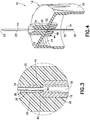
- the pen needle assembly 10 generally includes a hub 12, a first needle cannula 14, and a second needle cannula 16.
- the pen needle assembly 10 is for use with medical injectors, and is particularly well-suited for use with pen injectors.
- the hub 12 includes a body 18 having a transverse wall 20 from which extends proximally a skirt 22.
- the pen needle assembly 10 is formed to be removably mounted to a medical injector.
- features 24 may be disposed on the hub 12, preferably on the skirt 22, for providing mounting onto an injector.
- the features 24 may include cooperating mechanical elements, such as threads, detents, bayonet-type locking elements, and so forth, and/or surface configurations, such as a tapered Luer surface for frictional engagement.
- the hub 12 may be formed of a polymeric material, such as a thermoplastic.
- the first needle cannula 14 extends distally from the transverse wall 20 and terminates at a distal end 26, which is formed for insertion into a patient.
- a first lumen 28 is defined in the first needle cannula 14 which extends proximally from the distal end 26.
- the second needle cannula 16 extends proximally from the transverse wall 20 and terminates at a proximal end 30.
- a second lumen 32 is defined within the second needle cannula 16 which extends distally from the proximal end 30.
- the first and second needle cannulas 14, 16 are fixed relative to the hub 12 with the first and second lumen 28, 30 being in communication. In this manner, a continuous flow channel is defined from the proximal end 30 to the distal end 26.
- the first needle cannula 14 extends from the transverse wall 20 a sufficient distance so as to permit injection of the first needle cannula 14 into a patient to a desired depth.
- the second needle cannula 16 extends a sufficient distance from the transverse wall 20 to ensure that the proximal end 30 may come into communication with the contents of a reservoir or drug cartridge with the pen needle assembly 10 being mounted to an injector.
- the second needle cannula 16 With mounting of the pen needle assembly 10 onto an injector, the second needle cannula 16 will be caused to pierce through a sealing septum or stopper of a drug cartridge or reservoir.
- the second needle cannula 16 should be provided with sufficient length to obtain complete passage through the sealing septum or stopper with the proximal end 30 accessing the contents of the drug cartridge or reservoir.
- the first needle cannula 14 is formed to have a smaller external cross-section than the second needle cannula 16.
- the first needle cannula 14 is formed of a first gauge which is different from a second gauge of the second needle cannula 16.
- the second gauge is selected to provide a larger external cross-section than the first gauge.
- the first needle cannula 14, intended for injection into a patient is provided with a smaller profile than the second needle cannula 16.
- the second needle cannula 16 intended for accessing a drug cartridge or reservoir, provides for a more rigid needle structure which is more resistant to buckling than the first needle cannula 14 when subjected to force applied by a sealing stopper or septum.
- the first needle cannula 14 is a 31 or 32 gauge needle. With the first needle cannula 14 being a 32 gauge needle, it is preferred that the second needle cannula 16 be in the range of 25-31 gauge. Alternatively, with the first needle cannula 14 being a 31 gauge needle, it is preferred that the second needle cannula 16 be in the range of 25-30 gauge. It is noted that regular or reduced wall thickness gauges (e.g., thin wall; extra thin wall; ultra thin wall; micro thin wall) may be utilized. The following is a table setting forth inner and outer diameters of different needle gauges along with nominal wall thicknesses:
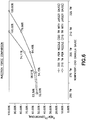
- a chart representing an injection force comparison.
- the chart includes two curves, one representing a 31 gauge thin wall needle and a second curve representing a 32 gauge thin wall needle.
- these needle sizes require substantially less injection force as compared to larger needle gauges.
- a 31 gauge thin wall needle requires 53.39% of the injection force of a 25 gauge thin wall needle
- a 32 gauge thin wall needle requires 52.03% of a 25 gauge thin wall needle.
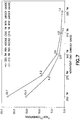
- a chart depicting critical buckling force ratios.
- the chart includes two curves, one representing a 31 gauge thin wall needle and a second curve representing a 32 gauge thin wall needle.
- larger gauge needles provide substantially more buckling resistance than thinner gauge needles.
- a 25 gauge thin wall needle provides 22.7 times more resistance to buckling than a 32 gauge thin wall needle
- a 25 gauge thin wall needle provides 15.3 times more resistance to buckling than a 31 gauge thin wall needle.
- a pen needle assembly 10 may be provided which advantageously provides good characteristics both for a needle section intended for injection and a needle section intended for accessing contents of a drug reservoir or cartridge.
- injection force may be minimized.
- greater buckling resistance may be provided.
- the first and second needle cannulas 14, 16 may be fixed to the hub 12 in any known manner.
- the first and second needle cannulas 14, 16 may be directly fixed to the transverse wall 20.
- a collar 34 may be provided which extends longitudinally from the transverse wall 20 and in which is defined a channel 36.
- the first and second needle cannulas 14, 16 may be fixed in the channel 36 preferably by adhesive 38.
- Other fixation methods may be used, including insert molding.
- the second lumen 32 may be larger than the first lumen 28.
- portions 40 of the second lumen 32 may radially extend outwardly from the first needle cannula 14. These portions 40 may be sealed to prevent leakage therefrom, e.g., by use of the adhesive 38 in the channel 36 or the inclusion of a different sealant material.
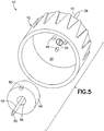
- a portion of the transverse wall 20 is located adjacent to a distal end 42 of the second needle cannula 16, as shown in Figure 3 .
- the transverse wall 20 limits distal movement of the second needle cannula 16 relative to the hub 12.
- the transverse wall 20 in this arrangement overlaps the portions 40 of the second lumen 32 which extend radially beyond the first needle cannula 14. This provides a sealing effect and/or an additional sealing effect beyond that provided by the adhesive 38 or other sealant material.
- the first and second needle cannulas 14, 16 may be fixed to the hub 12 using other techniques.
- the first needle cannula 14 may be fixed to the transverse wall 20 in the same manner as described above, with the second needle cannula 16 being pre-mounted to a mounting collar 44, preferably using adhesive 46.
- the mounting collar 44 is secured to the transverse wall 20 using any known technique, including adhesion and/or fusion.
- cooperating mounting pins 48 on the mounting collar 44 and/or the transverse wall 20 may be utilized which are formed to seat within corresponding mounting apertures 50.
- the first needle cannula 14 may be positioned so as to be partially inserted into the second needle cannula 16 if corresponding sizing permits. If the first needle cannula 14 cannot be telescoped within the second needle cannula 16, e.g., the second lumen 32 is smaller than the external cross-section of the first needle cannula 14, it is preferred that the first and second needle cannulas 14, 16 meet end-to-end in series.
- the distal end 42 of the second needle cannula 16 may be located relative to the hub 12 by interengagement with the transverse wall 20, for example, as shown in Figures 2 and 3 , or by positioning to be generally coplanar with a distal face 52 of the mounting collar 44.
- a proximal end 54 of the first needle cannula 14 may be located to define an interface with the distal end 42 of the second needle cannula 16 by being properly positioned axially within the channel 36.
- the first needle cannula 14 is disposed into the channel 36, prior to assembly with the second needle cannula 16, with a spacer or pin engaging the proximal end 54 to limit the extent of insertion into the channel 36 so that the proximal end 54 is located at a desired position.
- the second needle cannula 16 is fixed to the hub 12 by either insertion into the channel 36 or by mounting of the mounting collar 44. With mounting of the second needle cannula 16 to the hub 12, the distal end 42 of the second needle cannula 16 may be located to define an interface with the proximal end 54 of the first needle cannula 14.
Claims (6)
- Unité d'aiguille pour injecteur de type stylo (10) comprenant :un pavillon (12) ayant un corps (18) avec une paroi transversale (20) ;un moyen, disposé sur ledit pavillon (12) de manière proximale par rapport à ladite paroi transversale (20), pour monter ledit pavillon (12) sur un injecteur ;une première canule d'aiguille (14) s'étendant distalement à partir de ladite paroi transversale (20), ladite première canule d'aiguille (14) se terminant au niveau d'une extrémité distale (26), formée pour être insérée dans un patient, avec une première lumière (28) s'étendant proximalement à partir de ladite extrémité distale (26), ladite première canule d'aiguille (14) comprend une extrémité proximale (54), ladite première canule d'aiguille (14) étant d'un premier calibre ; et,une seconde canule d'aiguille (16), distincte de ladite première canule d'aiguille (14), ladite seconde canule d'aiguille fixée à l'intérieur d'un collier de montage et s'étendant proximalement à partir de ladite paroi transversale (20), ladite seconde canule d'aiguille (16) se terminant au niveau de l'extrémité proximale (54) avec une seconde lumière (32) s'étendant proximalement à partir de ladite extrémité proximale (54), ladite seconde canule d'aiguille (16) comprend une extrémité distale (42), dans laquelle, lesdites première et seconde lumières (32, 33) étant généralement coaxiales le long d'un axe longitudinal avec ladite extrémité proximale (54) de ladite première canule d'aiguille (14) étant généralement coplanaire avec ladite extrémité distale (42) de ladite seconde canule d'aiguille (16) à l'intérieur d'un plan disposé de manière transversale par rapport audit axe longitudinal et avec lesdites première et seconde lumières (32, 33) étant en communication et ladite extrémité distale de ladite seconde canule d'aiguille (16) étant coplanaire avec une face distale dudit collier de montage, etdans laquelle, ladite seconde canule d'aiguille (16) étant d'un second calibre, ledit second calibre définissant une section transversale externe (3) plus grande que ledit premier calibre.
- Unité d'aiguille pour injecteur de type stylo (10) selon la revendication 1, dans laquelle ledit pavillon (12) comprend une jupe (22) s'étendant proximalement à partir de ladite paroi transversale (20).
- Unité d'aiguille pour injecteur de type stylo (10) selon la revendication 2, dans laquelle ledit moyen de montage dudit pavillon (12) sur un injecteur est disposé sur ladite jupe (22).
- Unité d'aiguille pour injecteur de type stylo (10) selon la revendication 1, dans laquelle ladite extrémité distale de ladite seconde canule d'aiguille (16) se trouve en contact d'étanchéité avec ladite paroi transversale (20).
- Unité d'aiguille pour injecteur de type stylo (10) selon la revendication 1, dans laquelle ledit collier de montage est fixé à ladite paroi transversale (20).
- Unité d'aiguille pour injecteur de type stylo (10) selon la revendication 5, dans laquelle ladite extrémité distale (42) de ladite seconde canule d'aiguille (16) se trouve en prise mutuelle avec ladite paroi transversale (20) au niveau d'une partie dudit collier de montage.
Applications Claiming Priority (1)
| Application Number | Priority Date | Filing Date | Title |
|---|---|---|---|
| US12/963,849 US8608710B2 (en) | 2010-12-09 | 2010-12-09 | Pen needle assembly with different gauge needle cannulas |
Publications (2)
| Publication Number | Publication Date |
|---|---|
| EP2462970A1 EP2462970A1 (fr) | 2012-06-13 |
| EP2462970B1 true EP2462970B1 (fr) | 2018-02-07 |
Family
ID=45093530
Family Applications (1)
| Application Number | Title | Priority Date | Filing Date |
|---|---|---|---|
| EP11191748.0A Active EP2462970B1 (fr) | 2010-12-09 | 2011-12-02 | Unité d'aiguille pour injecteur de type stylo avec canules distale et proximale de calibre différent |
Country Status (5)
| Country | Link |
|---|---|
| US (1) | US8608710B2 (fr) |
| EP (1) | EP2462970B1 (fr) |
| JP (1) | JP6140922B2 (fr) |
| CA (1) | CA2759136C (fr) |
| ES (1) | ES2668226T3 (fr) |
Families Citing this family (23)
| Publication number | Priority date | Publication date | Assignee | Title |
|---|---|---|---|---|
| US20070202186A1 (en) | 2006-02-22 | 2007-08-30 | Iscience Interventional Corporation | Apparatus and formulations for suprachoroidal drug delivery |
| FR2934030B1 (fr) * | 2008-07-18 | 2010-09-17 | Commissariat Energie Atomique | Raccord fluidique male polyvalent pour dispositif de raccordement, et un tel dispositif l'incorporant |
| CN106214321B (zh) | 2010-10-15 | 2018-08-28 | 科尼尔赛德生物医学公司 | 用于进入眼睛的装置 |
| WO2012132829A1 (fr) * | 2011-03-25 | 2012-10-04 | テルモ株式会社 | Aiguille à deux extrémités et instrument de mélange |
| US9504603B2 (en) * | 2012-04-02 | 2016-11-29 | Ocuject, Llc | Intraocular delivery devices and methods therefor |
| WO2014074823A1 (fr) | 2012-11-08 | 2014-05-15 | Clearside Biomedical, Inc. | Procédés et dispositifs pour le traitement de maladies oculaires chez des sujets humains |
| CA2895757C (fr) * | 2012-12-26 | 2021-07-06 | Becton, Dickinson And Company | Ensemble aiguille stylo |
| CN105246529B (zh) | 2013-05-03 | 2019-06-14 | 科尼尔赛德生物医学公司 | 用于眼部注射的设备和方法 |
| WO2014197317A1 (fr) | 2013-06-03 | 2014-12-11 | Clearside Biomedical, Inc. | Appareil et procédés pour une administration de médicament à l'aide de multiples réservoirs |
| DE102013014885A1 (de) * | 2013-09-06 | 2015-03-12 | Braunform Gmbh | Verwendung eines Werkzeugs zum Spritzgießen eines Kunststoffkörpers |
| USD770043S1 (en) * | 2013-10-29 | 2016-10-25 | Htl-Strefa Spolka Akcyjna | Needle hub |
| JP2017524419A (ja) | 2014-06-20 | 2017-08-31 | クリアサイド バイオメディカル,インコーポレイテッド | 薬剤送達のための挿入深さを制御するための可変径カニューレ及び方法 |
| WO2016016419A1 (fr) * | 2014-07-31 | 2016-02-04 | Novo Nordisk A/S | Tube d'aiguille et procédé de production d'aiguilles d'injection |
| JP6787934B2 (ja) * | 2015-06-01 | 2020-11-18 | ベクトン・ディキンソン・アンド・カンパニーBecton, Dickinson And Company | 短縮された非患者側端部を含む使い捨てのペン注射針、および再使用可能なペンインタフェース |
| USD878575S1 (en) * | 2015-11-24 | 2020-03-17 | Visionisti Oy | Hand operated medical instrument |
| EP3413851B1 (fr) | 2016-02-10 | 2023-09-27 | Clearside Biomedical, Inc. | Emballage |
| USD787054S1 (en) * | 2016-04-14 | 2017-05-16 | Becton, Dickinson And Company | Pen needle hub |
| WO2017192565A1 (fr) | 2016-05-02 | 2017-11-09 | Clearside Biomedical, Inc. | Systèmes et méthodes pour l'administration de médicaments par voie ophtalmique |
| IL305537A (en) | 2016-08-12 | 2023-10-01 | Clearside Biomedical Inc | Devices and methods for adjusting the insertion depth of a drug administration needle |
| CA3033762A1 (fr) * | 2016-08-19 | 2018-02-22 | Becton, Dickinson And Company | Ensemble d'adaptateur pour fixation a un flacon |
| EP3752224A4 (fr) | 2018-02-12 | 2021-11-03 | Becton, Dickinson and Company | Système d'aiguille de stylo |
| WO2021118899A1 (fr) * | 2019-12-12 | 2021-06-17 | Becton, Dickinson And Company | Appareil stylo injecteur |
| PL435654A1 (pl) * | 2020-10-12 | 2022-04-19 | Rozwadowski Marcin Aureum.Tech | Podzespół pasywnej osłonki końcówki nieiniekcyjnej igły i zespół sterylnej igły jednorazowego użytku z podzespołem pasywnej osłonki końcówki nieiniekcyjnej igły, oraz części składowe zawarte w tym podzespole pasywnej osłonki końcówki nieiniekcyjnej igły i produkty medyczne zawierające ten zespół sterylnej igły jednorazowego użytku z tym podzespołem pasywnej osłonki końcówki nieiniekcyjnej igły |
Citations (1)
| Publication number | Priority date | Publication date | Assignee | Title |
|---|---|---|---|---|
| US20030050602A1 (en) * | 2001-09-12 | 2003-03-13 | Pettis Ronald J. | Microneedle-based pen device for drug delivery and method for using same |
Family Cites Families (7)
| Publication number | Priority date | Publication date | Assignee | Title |
|---|---|---|---|---|
| US3884229A (en) | 1973-11-29 | 1975-05-20 | Burron Medical Prod Inc | Hypodermic syringe and needle assembly |
| US4266543A (en) | 1979-02-22 | 1981-05-12 | Blum Alvin S | Hypodermic needle protection means |
| JPS5731870A (en) | 1980-08-05 | 1982-02-20 | Korupo Kk | Injector |
| US5133362A (en) | 1990-12-28 | 1992-07-28 | Gerald Moss | Needle for use with vacuum test tube blood sampling systems |
| JP4187922B2 (ja) | 2000-09-14 | 2008-11-26 | テルモ株式会社 | 液体注入針および液体注入装置 |
| WO2002076540A1 (fr) * | 2001-03-23 | 2002-10-03 | Novo Nordisk A/S | Canule ; procede de fabrication et methode d'utilisation |
| DE102008025011B4 (de) * | 2008-05-24 | 2022-12-22 | Tecpharma Licensing Ag | Ampulle mit Ampullenhalterung |
-
2010
- 2010-12-09 US US12/963,849 patent/US8608710B2/en active Active
-
2011
- 2011-11-21 CA CA2759136A patent/CA2759136C/fr active Active
- 2011-12-02 EP EP11191748.0A patent/EP2462970B1/fr active Active
- 2011-12-02 ES ES11191748.0T patent/ES2668226T3/es active Active
- 2011-12-08 JP JP2011268871A patent/JP6140922B2/ja active Active
Patent Citations (1)
| Publication number | Priority date | Publication date | Assignee | Title |
|---|---|---|---|---|
| US20030050602A1 (en) * | 2001-09-12 | 2003-03-13 | Pettis Ronald J. | Microneedle-based pen device for drug delivery and method for using same |
Also Published As
| Publication number | Publication date |
|---|---|
| US20120150128A1 (en) | 2012-06-14 |
| EP2462970A1 (fr) | 2012-06-13 |
| JP6140922B2 (ja) | 2017-06-07 |
| JP2012120844A (ja) | 2012-06-28 |
| CA2759136C (fr) | 2017-07-04 |
| ES2668226T3 (es) | 2018-05-17 |
| US8608710B2 (en) | 2013-12-17 |
| CA2759136A1 (fr) | 2012-06-09 |
Similar Documents
| Publication | Publication Date | Title |
|---|---|---|
| EP2462970B1 (fr) | Unité d'aiguille pour injecteur de type stylo avec canules distale et proximale de calibre différent | |
| AU2019271944B2 (en) | Needle assemblies with flashback indicator and related methods | |
| CN112089964B (zh) | 具有自切缝针的柔顺导管接头 | |
| US11246996B2 (en) | Pen needle assembly | |
| US8202461B2 (en) | Flow elements for use with flexible spinal needles, needle assemblies for manufacture and methods therefor | |
| US20030208160A1 (en) | Needle assembly | |
| EP2240223B1 (fr) | Dispositif d'administration de médicament pour suspensions médicamenteuses | |
| US20220273888A1 (en) | Variable length injection syringe | |
| JP7459062B2 (ja) | 注射器アセンブリとアダプタ部材 | |
| US20230166087A1 (en) | Needle assembly and related methods | |
| WO2016016419A1 (fr) | Tube d'aiguille et procédé de production d'aiguilles d'injection |
Legal Events
| Date | Code | Title | Description |
|---|---|---|---|
| PUAI | Public reference made under article 153(3) epc to a published international application that has entered the european phase |
Free format text: ORIGINAL CODE: 0009012 |
|
| AK | Designated contracting states |
Kind code of ref document: A1 Designated state(s): AL AT BE BG CH CY CZ DE DK EE ES FI FR GB GR HR HU IE IS IT LI LT LU LV MC MK MT NL NO PL PT RO RS SE SI SK SM TR |
|
| AX | Request for extension of the european patent |
Extension state: BA ME |
|
| 17P | Request for examination filed |
Effective date: 20121204 |
|
| 17Q | First examination report despatched |
Effective date: 20150713 |
|
| RAP1 | Party data changed (applicant data changed or rights of an application transferred) |
Owner name: BECTON, DICKINSON AND COMPANY |
|
| GRAP | Despatch of communication of intention to grant a patent |
Free format text: ORIGINAL CODE: EPIDOSNIGR1 |
|
| INTG | Intention to grant announced |
Effective date: 20170425 |
|
| RIN1 | Information on inventor provided before grant (corrected) |
Inventor name: ZHAO, YING |
|
| GRAS | Grant fee paid |
Free format text: ORIGINAL CODE: EPIDOSNIGR3 |
|
| GRAJ | Information related to disapproval of communication of intention to grant by the applicant or resumption of examination proceedings by the epo deleted |
Free format text: ORIGINAL CODE: EPIDOSDIGR1 |
|
| GRAL | Information related to payment of fee for publishing/printing deleted |
Free format text: ORIGINAL CODE: EPIDOSDIGR3 |
|
| INTC | Intention to grant announced (deleted) | ||
| GRAP | Despatch of communication of intention to grant a patent |
Free format text: ORIGINAL CODE: EPIDOSNIGR1 |
|
| INTG | Intention to grant announced |
Effective date: 20171020 |
|
| GRAA | (expected) grant |
Free format text: ORIGINAL CODE: 0009210 |
|
| AK | Designated contracting states |
Kind code of ref document: B1 Designated state(s): AL AT BE BG CH CY CZ DE DK EE ES FI FR GB GR HR HU IE IS IT LI LT LU LV MC MK MT NL NO PL PT RO RS SE SI SK SM TR |
|
| REG | Reference to a national code |
Ref country code: GB Ref legal event code: FG4D |
|
| REG | Reference to a national code |
Ref country code: AT Ref legal event code: REF Ref document number: 968537 Country of ref document: AT Kind code of ref document: T Effective date: 20180215 Ref country code: CH Ref legal event code: EP |
|
| REG | Reference to a national code |
Ref country code: IE Ref legal event code: FG4D |
|
| REG | Reference to a national code |
Ref country code: DE Ref legal event code: R096 Ref document number: 602011045511 Country of ref document: DE |
|
| REG | Reference to a national code |
Ref country code: ES Ref legal event code: FG2A Ref document number: 2668226 Country of ref document: ES Kind code of ref document: T3 Effective date: 20180517 |
|
| REG | Reference to a national code |
Ref country code: NL Ref legal event code: MP Effective date: 20180207 |
|
| REG | Reference to a national code |
Ref country code: AT Ref legal event code: MK05 Ref document number: 968537 Country of ref document: AT Kind code of ref document: T Effective date: 20180207 |
|
| PG25 | Lapsed in a contracting state [announced via postgrant information from national office to epo] |
Ref country code: HR Free format text: LAPSE BECAUSE OF FAILURE TO SUBMIT A TRANSLATION OF THE DESCRIPTION OR TO PAY THE FEE WITHIN THE PRESCRIBED TIME-LIMIT Effective date: 20180207 Ref country code: NO Free format text: LAPSE BECAUSE OF FAILURE TO SUBMIT A TRANSLATION OF THE DESCRIPTION OR TO PAY THE FEE WITHIN THE PRESCRIBED TIME-LIMIT Effective date: 20180507 Ref country code: FI Free format text: LAPSE BECAUSE OF FAILURE TO SUBMIT A TRANSLATION OF THE DESCRIPTION OR TO PAY THE FEE WITHIN THE PRESCRIBED TIME-LIMIT Effective date: 20180207 Ref country code: CY Free format text: LAPSE BECAUSE OF FAILURE TO SUBMIT A TRANSLATION OF THE DESCRIPTION OR TO PAY THE FEE WITHIN THE PRESCRIBED TIME-LIMIT Effective date: 20180207 Ref country code: LT Free format text: LAPSE BECAUSE OF FAILURE TO SUBMIT A TRANSLATION OF THE DESCRIPTION OR TO PAY THE FEE WITHIN THE PRESCRIBED TIME-LIMIT Effective date: 20180207 Ref country code: NL Free format text: LAPSE BECAUSE OF FAILURE TO SUBMIT A TRANSLATION OF THE DESCRIPTION OR TO PAY THE FEE WITHIN THE PRESCRIBED TIME-LIMIT Effective date: 20180207 |
|
| PG25 | Lapsed in a contracting state [announced via postgrant information from national office to epo] |
Ref country code: SE Free format text: LAPSE BECAUSE OF FAILURE TO SUBMIT A TRANSLATION OF THE DESCRIPTION OR TO PAY THE FEE WITHIN THE PRESCRIBED TIME-LIMIT Effective date: 20180207 Ref country code: IS Free format text: LAPSE BECAUSE OF FAILURE TO SUBMIT A TRANSLATION OF THE DESCRIPTION OR TO PAY THE FEE WITHIN THE PRESCRIBED TIME-LIMIT Effective date: 20180607 Ref country code: LV Free format text: LAPSE BECAUSE OF FAILURE TO SUBMIT A TRANSLATION OF THE DESCRIPTION OR TO PAY THE FEE WITHIN THE PRESCRIBED TIME-LIMIT Effective date: 20180207 Ref country code: GR Free format text: LAPSE BECAUSE OF FAILURE TO SUBMIT A TRANSLATION OF THE DESCRIPTION OR TO PAY THE FEE WITHIN THE PRESCRIBED TIME-LIMIT Effective date: 20180508 Ref country code: PL Free format text: LAPSE BECAUSE OF FAILURE TO SUBMIT A TRANSLATION OF THE DESCRIPTION OR TO PAY THE FEE WITHIN THE PRESCRIBED TIME-LIMIT Effective date: 20180207 Ref country code: RS Free format text: LAPSE BECAUSE OF FAILURE TO SUBMIT A TRANSLATION OF THE DESCRIPTION OR TO PAY THE FEE WITHIN THE PRESCRIBED TIME-LIMIT Effective date: 20180207 Ref country code: BG Free format text: LAPSE BECAUSE OF FAILURE TO SUBMIT A TRANSLATION OF THE DESCRIPTION OR TO PAY THE FEE WITHIN THE PRESCRIBED TIME-LIMIT Effective date: 20180507 Ref country code: AT Free format text: LAPSE BECAUSE OF FAILURE TO SUBMIT A TRANSLATION OF THE DESCRIPTION OR TO PAY THE FEE WITHIN THE PRESCRIBED TIME-LIMIT Effective date: 20180207 |
|
| PG25 | Lapsed in a contracting state [announced via postgrant information from national office to epo] |
Ref country code: RO Free format text: LAPSE BECAUSE OF FAILURE TO SUBMIT A TRANSLATION OF THE DESCRIPTION OR TO PAY THE FEE WITHIN THE PRESCRIBED TIME-LIMIT Effective date: 20180207 Ref country code: AL Free format text: LAPSE BECAUSE OF FAILURE TO SUBMIT A TRANSLATION OF THE DESCRIPTION OR TO PAY THE FEE WITHIN THE PRESCRIBED TIME-LIMIT Effective date: 20180207 Ref country code: EE Free format text: LAPSE BECAUSE OF FAILURE TO SUBMIT A TRANSLATION OF THE DESCRIPTION OR TO PAY THE FEE WITHIN THE PRESCRIBED TIME-LIMIT Effective date: 20180207 |
|
| REG | Reference to a national code |
Ref country code: DE Ref legal event code: R097 Ref document number: 602011045511 Country of ref document: DE |
|
| PG25 | Lapsed in a contracting state [announced via postgrant information from national office to epo] |
Ref country code: SK Free format text: LAPSE BECAUSE OF FAILURE TO SUBMIT A TRANSLATION OF THE DESCRIPTION OR TO PAY THE FEE WITHIN THE PRESCRIBED TIME-LIMIT Effective date: 20180207 Ref country code: CZ Free format text: LAPSE BECAUSE OF FAILURE TO SUBMIT A TRANSLATION OF THE DESCRIPTION OR TO PAY THE FEE WITHIN THE PRESCRIBED TIME-LIMIT Effective date: 20180207 Ref country code: DK Free format text: LAPSE BECAUSE OF FAILURE TO SUBMIT A TRANSLATION OF THE DESCRIPTION OR TO PAY THE FEE WITHIN THE PRESCRIBED TIME-LIMIT Effective date: 20180207 Ref country code: SM Free format text: LAPSE BECAUSE OF FAILURE TO SUBMIT A TRANSLATION OF THE DESCRIPTION OR TO PAY THE FEE WITHIN THE PRESCRIBED TIME-LIMIT Effective date: 20180207 |
|
| PLBE | No opposition filed within time limit |
Free format text: ORIGINAL CODE: 0009261 |
|
| STAA | Information on the status of an ep patent application or granted ep patent |
Free format text: STATUS: NO OPPOSITION FILED WITHIN TIME LIMIT |
|
| 26N | No opposition filed |
Effective date: 20181108 |
|
| PG25 | Lapsed in a contracting state [announced via postgrant information from national office to epo] |
Ref country code: SI Free format text: LAPSE BECAUSE OF FAILURE TO SUBMIT A TRANSLATION OF THE DESCRIPTION OR TO PAY THE FEE WITHIN THE PRESCRIBED TIME-LIMIT Effective date: 20180207 |
|
| REG | Reference to a national code |
Ref country code: CH Ref legal event code: PL |
|
| PG25 | Lapsed in a contracting state [announced via postgrant information from national office to epo] |
Ref country code: MC Free format text: LAPSE BECAUSE OF FAILURE TO SUBMIT A TRANSLATION OF THE DESCRIPTION OR TO PAY THE FEE WITHIN THE PRESCRIBED TIME-LIMIT Effective date: 20180207 Ref country code: LU Free format text: LAPSE BECAUSE OF NON-PAYMENT OF DUE FEES Effective date: 20181202 |
|
| REG | Reference to a national code |
Ref country code: IE Ref legal event code: MM4A |
|
| REG | Reference to a national code |
Ref country code: BE Ref legal event code: MM Effective date: 20181231 |
|
| PG25 | Lapsed in a contracting state [announced via postgrant information from national office to epo] |
Ref country code: IE Free format text: LAPSE BECAUSE OF NON-PAYMENT OF DUE FEES Effective date: 20181202 |
|
| PG25 | Lapsed in a contracting state [announced via postgrant information from national office to epo] |
Ref country code: BE Free format text: LAPSE BECAUSE OF NON-PAYMENT OF DUE FEES Effective date: 20181231 |
|
| PG25 | Lapsed in a contracting state [announced via postgrant information from national office to epo] |
Ref country code: CH Free format text: LAPSE BECAUSE OF NON-PAYMENT OF DUE FEES Effective date: 20181231 Ref country code: LI Free format text: LAPSE BECAUSE OF NON-PAYMENT OF DUE FEES Effective date: 20181231 |
|
| PG25 | Lapsed in a contracting state [announced via postgrant information from national office to epo] |
Ref country code: MT Free format text: LAPSE BECAUSE OF NON-PAYMENT OF DUE FEES Effective date: 20181202 |
|
| PG25 | Lapsed in a contracting state [announced via postgrant information from national office to epo] |
Ref country code: TR Free format text: LAPSE BECAUSE OF FAILURE TO SUBMIT A TRANSLATION OF THE DESCRIPTION OR TO PAY THE FEE WITHIN THE PRESCRIBED TIME-LIMIT Effective date: 20180207 |
|
| PG25 | Lapsed in a contracting state [announced via postgrant information from national office to epo] |
Ref country code: PT Free format text: LAPSE BECAUSE OF FAILURE TO SUBMIT A TRANSLATION OF THE DESCRIPTION OR TO PAY THE FEE WITHIN THE PRESCRIBED TIME-LIMIT Effective date: 20180207 |
|
| PG25 | Lapsed in a contracting state [announced via postgrant information from national office to epo] |
Ref country code: MK Free format text: LAPSE BECAUSE OF NON-PAYMENT OF DUE FEES Effective date: 20180207 Ref country code: HU Free format text: LAPSE BECAUSE OF FAILURE TO SUBMIT A TRANSLATION OF THE DESCRIPTION OR TO PAY THE FEE WITHIN THE PRESCRIBED TIME-LIMIT; INVALID AB INITIO Effective date: 20111202 |
|
| PGFP | Annual fee paid to national office [announced via postgrant information from national office to epo] |
Ref country code: IT Payment date: 20221122 Year of fee payment: 12 |
|
| PGFP | Annual fee paid to national office [announced via postgrant information from national office to epo] |
Ref country code: ES Payment date: 20230102 Year of fee payment: 12 |
|
| P01 | Opt-out of the competence of the unified patent court (upc) registered |
Effective date: 20230427 |
|
| P02 | Opt-out of the competence of the unified patent court (upc) changed |
Effective date: 20230530 |
|
| PGFP | Annual fee paid to national office [announced via postgrant information from national office to epo] |
Ref country code: GB Payment date: 20231121 Year of fee payment: 13 |
|
| PGFP | Annual fee paid to national office [announced via postgrant information from national office to epo] |
Ref country code: FR Payment date: 20231122 Year of fee payment: 13 Ref country code: DE Payment date: 20231121 Year of fee payment: 13 |
|
| PGFP | Annual fee paid to national office [announced via postgrant information from national office to epo] |
Ref country code: ES Payment date: 20240102 Year of fee payment: 13 |