EP2462012B1 - Anhänger-parkbremsenventilanordnung - Google Patents
Anhänger-parkbremsenventilanordnung Download PDFInfo
- Publication number
- EP2462012B1 EP2462012B1 EP10744710.4A EP10744710A EP2462012B1 EP 2462012 B1 EP2462012 B1 EP 2462012B1 EP 10744710 A EP10744710 A EP 10744710A EP 2462012 B1 EP2462012 B1 EP 2462012B1
- Authority
- EP
- European Patent Office
- Prior art keywords
- valve
- park
- way valve
- trailer
- pressure
- Prior art date
- Legal status (The legal status is an assumption and is not a legal conclusion. Google has not performed a legal analysis and makes no representation as to the accuracy of the status listed.)
- Not-in-force
Links
Images
Classifications
-
- B—PERFORMING OPERATIONS; TRANSPORTING
- B60—VEHICLES IN GENERAL
- B60T—VEHICLE BRAKE CONTROL SYSTEMS OR PARTS THEREOF; BRAKE CONTROL SYSTEMS OR PARTS THEREOF, IN GENERAL; ARRANGEMENT OF BRAKING ELEMENTS ON VEHICLES IN GENERAL; PORTABLE DEVICES FOR PREVENTING UNWANTED MOVEMENT OF VEHICLES; VEHICLE MODIFICATIONS TO FACILITATE COOLING OF BRAKES
- B60T7/00—Brake-action initiating means
- B60T7/12—Brake-action initiating means for automatic initiation; for initiation not subject to will of driver or passenger
- B60T7/20—Brake-action initiating means for automatic initiation; for initiation not subject to will of driver or passenger specially for trailers, e.g. in case of uncoupling of or overrunning by trailer
-
- B—PERFORMING OPERATIONS; TRANSPORTING
- B60—VEHICLES IN GENERAL
- B60T—VEHICLE BRAKE CONTROL SYSTEMS OR PARTS THEREOF; BRAKE CONTROL SYSTEMS OR PARTS THEREOF, IN GENERAL; ARRANGEMENT OF BRAKING ELEMENTS ON VEHICLES IN GENERAL; PORTABLE DEVICES FOR PREVENTING UNWANTED MOVEMENT OF VEHICLES; VEHICLE MODIFICATIONS TO FACILITATE COOLING OF BRAKES
- B60T13/00—Transmitting braking action from initiating means to ultimate brake actuator with power assistance or drive; Brake systems incorporating such transmitting means, e.g. air-pressure brake systems
- B60T13/10—Transmitting braking action from initiating means to ultimate brake actuator with power assistance or drive; Brake systems incorporating such transmitting means, e.g. air-pressure brake systems with fluid assistance, drive, or release
- B60T13/24—Transmitting braking action from initiating means to ultimate brake actuator with power assistance or drive; Brake systems incorporating such transmitting means, e.g. air-pressure brake systems with fluid assistance, drive, or release the fluid being gaseous
- B60T13/26—Compressed-air systems
- B60T13/261—Compressed-air systems systems with both indirect application and application by springs or weights and released by compressed air
- B60T13/263—Compressed-air systems systems with both indirect application and application by springs or weights and released by compressed air specially adapted for coupling with dependent systems, e.g. tractor-trailer systems
-
- B—PERFORMING OPERATIONS; TRANSPORTING
- B60—VEHICLES IN GENERAL
- B60T—VEHICLE BRAKE CONTROL SYSTEMS OR PARTS THEREOF; BRAKE CONTROL SYSTEMS OR PARTS THEREOF, IN GENERAL; ARRANGEMENT OF BRAKING ELEMENTS ON VEHICLES IN GENERAL; PORTABLE DEVICES FOR PREVENTING UNWANTED MOVEMENT OF VEHICLES; VEHICLE MODIFICATIONS TO FACILITATE COOLING OF BRAKES
- B60T13/00—Transmitting braking action from initiating means to ultimate brake actuator with power assistance or drive; Brake systems incorporating such transmitting means, e.g. air-pressure brake systems
- B60T13/10—Transmitting braking action from initiating means to ultimate brake actuator with power assistance or drive; Brake systems incorporating such transmitting means, e.g. air-pressure brake systems with fluid assistance, drive, or release
- B60T13/24—Transmitting braking action from initiating means to ultimate brake actuator with power assistance or drive; Brake systems incorporating such transmitting means, e.g. air-pressure brake systems with fluid assistance, drive, or release the fluid being gaseous
- B60T13/26—Compressed-air systems
- B60T13/261—Compressed-air systems systems with both indirect application and application by springs or weights and released by compressed air
- B60T13/265—Compressed-air systems systems with both indirect application and application by springs or weights and released by compressed air dependent systems, e.g. trailer systems
-
- B—PERFORMING OPERATIONS; TRANSPORTING
- B60—VEHICLES IN GENERAL
- B60T—VEHICLE BRAKE CONTROL SYSTEMS OR PARTS THEREOF; BRAKE CONTROL SYSTEMS OR PARTS THEREOF, IN GENERAL; ARRANGEMENT OF BRAKING ELEMENTS ON VEHICLES IN GENERAL; PORTABLE DEVICES FOR PREVENTING UNWANTED MOVEMENT OF VEHICLES; VEHICLE MODIFICATIONS TO FACILITATE COOLING OF BRAKES
- B60T13/00—Transmitting braking action from initiating means to ultimate brake actuator with power assistance or drive; Brake systems incorporating such transmitting means, e.g. air-pressure brake systems
- B60T13/10—Transmitting braking action from initiating means to ultimate brake actuator with power assistance or drive; Brake systems incorporating such transmitting means, e.g. air-pressure brake systems with fluid assistance, drive, or release
- B60T13/66—Electrical control in fluid-pressure brake systems
- B60T13/68—Electrical control in fluid-pressure brake systems by electrically-controlled valves
- B60T13/683—Electrical control in fluid-pressure brake systems by electrically-controlled valves in pneumatic systems or parts thereof
Definitions
- the invention relates to a park brake valve arrangement for a trailer of a commercial vehicle tractor/trailer.
- Modem braking systems for tractor/trailer units are invariably fluid-operated, the fluid typically being air, for economic and practical reasons.
- a pressurised air supply is generated by an engine-driven compressor on the tractor which supplies air to the trailer through a supply line, so that when the service brake is applied by the driver, the brakes on the tractor and the trailer are applied by the supply of compressed air to the individual wheel brakes.
- a parking brake in which the braking force is supplied by a spring actuator, the brake being normally held off by an air supply.
- the control valve for the parking brake is operable manually to vent the valve to atmosphere and hence apply the parking brake.
- the driver has to decouple the supply line connection between the tractor and trailer and also an electrical connection through which electrical components on the trailer are connected to the tractor electrical supply.
- the correct procedure at this stage is that the driver should manually operate the parking brake valve to ensure that the parking brake is applied.
- the driver can then uncouple the pivotal connection between the tractor and trailer to enable the tractor to be driven away leaving the trailer in the parked condition.
- GB2417764 discloses a trailer park valve in which the parking brake is moved to a locked condition when the pneumatic and the electrical connection are removed. To release the valve from the locked position to the drive position, the driver has to manually reconnect both the electrical and pneumatic connections. Whilst this valve represents a significant safety enhancement over the prior art systems, the valve construction is different to the standard park and shunt valve arrangements in use.
- DE20122779 discloses a further park valve arrangement that is background prior art.
- a park valve arrangement for a trailer for a commercial vehicle having a main air supply line, electrical connection and a reservoir, which trailer is provided with spring applied brakes adapted to be held in an off position by pneumatic pressure, wherein the valve arrangement controls the application of pressure to the spring brakes such that when the main air supply is absent or disconnected the spring brakes are applied, wherein if the electrical connection is present, the spring brakes are applied but park control released, wherein if the electrical connection is disconnected, the spring brakes are applied but park control set such that the valve is operable with the main supply and electrical connection disconnected to enable the spring brakes to be released.
- air pressure is supplied from the reservoir to the inlet of the first two way valve and the inlet of the second two way valve, such that the electrically biased two valve provides a control signal to the park valve enabling this to remain in the Drive position.
- the electrically biased two way valve moves to a second position, opening its outlet and supplying a control signal to the park valve causing it to move to a second position in which the pressure to the spring brakes is exhausted via the exhaust, thereby the spring brakes being applied and the park control being set.
- the truck brake system will detect this condition and the truck brake system will attempt to apply the trailer brakes via the service (or “red”) line.
- the park brake is automatically set. The park brake then remains set and continues to brake until it is manually reset, which can cause problems if the pressure is returned to the service line.
- the present invention advantageously provides that if the control line is cut or open, then the electrical connection ensures that the brakes are applied but if the service line pressure is released then the trailer brakes will still work, thereby ensuring compliance with Regulation ECE13.
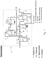
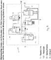
- Figure 1 shows schematically a valve arrangement 10 in which air is supplied from a main supply line 1 to a manually operable shunt valve 12.
- the outlet of the shunt valve 12 is passed to an inlet of a two way valve 13 via a non-return valve 18, which two way valve 13 is pressure biased with a non-return, and to the control port of a pressured biased two valve 14.
- a first outlet of the valve 13 is connected to an inlet of a park valve 15 and a second outlet of the valve 13 is connected to an exhaust 3.
- the two way valve 14 also receives an input from a trailer based reservoir, which input is also in pneumatic connection with an outlet of the shunt valve 12 and the inlet of the valve 13.
- the outlet of the two way valve 14 is connected to an inlet of an electrically biased two way valve 16, the outlet of which provides the pneumatic control signal to the park valve 15.
- a first outlet of the park valve 15 is connected to the spring brakes of the trailer and a second outlet of the park valve 15 is connected to the exhaust 3.
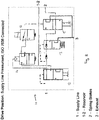
- FIG 2 shows the valve arrangement in the Drive position, in which the main supply line 1 is pressurised and the ISO 7638 electrical connection from the tractor to the trailer EBS is connected.
- the shunt valve 12 is in fluid connection with the inlet of two way valve 13 and supplies a control signal to the control input of the two way valve 14.
- the outlet of the two valve way 13 is in fluid connection with the inlet of the park valve 15, which supplies pressure to the spring brakes 2. As the spring brakes are biased into the on position, this pressure holds the spring brakes off.
- the main supply line is also in fluid communication with the reservoir and accordingly can charge this as necessary.
- the control signal supplied to the valve 14 ensures that the outlet of the valve 14 is closed and accordingly the valve 16 is unpressurised and there is no control signal to the park valve 15.
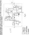
- Figure 3 shows the valve arrangement when the automatic brake is applied.
- the main supply line is exhausted but the electrical connection from the ISO 7638 connector is still present.
- This condition could, for example, indicate an incipient break away.
- the spring brakes are applied but the park control remains released.
- the output of shunt valve 12 is depressurised and hence the control signal to the two way valve 14 is changed, causing this to change position.
- air pressure is supplied from the reservoir to the inlet of the two way valve 13 and the inlet of the two way valve 14.
- the fluid connection between the two way valve 14 and the electrically biased two way valve 16 is pressurised but the outlet of the two way valve 16 is closed so that the control signal to the park valve 15 remains the same as in the Drive position.
- the pressure bias of this valve causes it to move to a second position removing the air supply to the park valve 15, which is accordingly depressurised via two way valve 16 to the exhaust 3. There is accordingly no pressure on the outlet of the park valve 15 and hence no pressure to withhold the spring brakes, which are then applied. In this condition the park valve 15 is not directly connected to the exhaust and so the park control remains released.
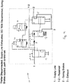
- Figure 4 shows the valve arrangement when the pneumatic connection trailer has been completely disconnected from the tractor. This could occur, for example, when the trailer is parked or if it has broken away from the tractor. In this condition, the main supply line is exhausted and the IS07638 is disconnected so that the trailer has no electrical supply. This results in the spring brakes being applied and the park control being set. In the absence of the main supply line, the output of shunt valve 12 is depressurized and the control signal to the two way valve 14 is changed from the Drive position, causing this valve to change position. The inlet of the two way valve 14 is still pressurized from the reservoir and the outlet supplies a pressure to the valve 16.
- the electrically biased two way valve 16 now no longer receives an electrical control signal, it moves to a second position, opening its outlet and supplying a control signal to the park valve 15 causing it to move to a second position in which the pressure to the spring brakes is exhausted via the exhaust 3 and the connection to the two valve 13 is closed, although the outlet of this valve also remains depressurized.
- the spring brakes remain applied until they are manually reset.
- Figure 5 shows the valve in the condition for manoeuvring as it is sometimes necessary to move a parked disconnected trailer when a tractor is not present, for example in a loading depot.
- the shunt valve 12 is manually actuated to the position shown in Figure 5 , in which it receives a supply pressure from the reservoir and can supply a control pressure to the two way valve 14. Supplying this control pressure causes the valve 14 to close its outlet and remove the pressure in the conduit to the valve 16, which in turn removes the control signal from the park valve 15.
- valve 15 This allows the valve 15 to be moved to the position it has in the Drive position and a pressure is then supplied via the two way valve 13 to the valve 15 and to the spring brakes. This supply of pressure to the spring brakes biases them to the off position so that it becomes possible to move the trailer.
- valve 13 could be moved to another component in the braking system such as the EBS - in this case the other component would be a valve located after port 2.
- valve arrangement of the invention has the advantage over known alternatives in that it can be offered as an add-on to other products and so need not be included in markets where this type of valve is not desired or required.
Landscapes
- Engineering & Computer Science (AREA)
- Transportation (AREA)
- Mechanical Engineering (AREA)
- Valves And Accessory Devices For Braking Systems (AREA)
- Braking Systems And Boosters (AREA)
Claims (9)
- Parkbremsenventilanordnung für einen Anhänger für ein Nutzfahrzeug mit einer Hauptzufuhrleitung (1), einer elektrischen Verbindung und einem Reservoir, wobei der Anhänger mit Federkraftbremsen (2) ausgestattet ist, die so ausgelegt sind, dass sie durch pneumatischen Druck in einer Aus-Position gehalten werden, dadurch gekennzeichnet, dass die Ventilanordnung die Druckbeaufschlagung der Federbremsen (2) so steuert, dass, wenn die Hauptzufuhr (1) nicht vorhanden oder getrennt ist, die Federbremsen (2) betätigt werden, wobei, wenn die elektrischen Verbindung vorhanden ist, die Federbremsen (2) betätigt werden, aber die Parkbremse gelöst werden kann, wobei, wenn die elektrische Verbindung unterbrochen ist, die Federbremsen (2) betätigt werden, die Parkbremsung jedoch so erfolgt, dass die Ventilanordnung bei getrennter Hauptzufuhrleitung (1) und elektrischer Verbindung dahingehend betriebsfähig ist, dass sie ein Lösen der Federbremsen (2) ermöglicht.
- Parkbremsenventilanordnung nach Anspruch 2, wobei die Anordnung ein Shuntventil (12) umfasst, dass darauf ausgelegt ist, Luft von der Hauptzufuhrleitung (1) aufzunehmen, wobei das Shuntventil (12) mit einem Zweiwegeventil (13) verbunden ist und das Zweiwegeventil (13) mit einem Parkventil (15) verbunden ist und das Parkventil (15) so ausgelegt ist, dass es eine Parkbremsung bereitstellt.
- Parkbremsenventilanordnung nach Anspruch 2, wobei das Shuntventil (12) parallel zum ersten Zweiwegeventil (13) weiter mit einem zweiten Zweiwegeventil (14) verbunden ist und das zweite Zweiwegeventil (14) mit einem elektrisch gestellten Zweiwegeventil (16) verbunden ist, dessen Ausgabe mit dem Parkventil (15) verbunden ist.
- Parkbremsenventilanordnung nach Anspruch 3, wobei, wenn die Hauptzufuhr (1) entlüftet und eine elektrische Verbindung vorhanden ist, Luftdruck vom Reservoir zum Einlass des ersten Zweiwegeventils (13) und zum Einlass des zweiten Zweiwegeventil (14) geführt wird, so dass das elektrisch gestellte Zweiwegeventil (16) ein Steuersignal an das Parkventil (15) schickt, das es diesem ermöglicht, in der Fahrposition zu bleiben.
- Parkbremsenventilanordnung nach Anspruch 3 oder Anspruch 4, wobei sich, wenn die elektrische Verbindung getrennt ist, das elektrisch gestellte Zweiwegeventil (16) in eine zweite Position bewegt, wodurch sich sein Auslass öffnet und ein Steuersignal an das Parkventil (15) schickt, das dieses dazu veranlasst, sich in eine zweite Position zu bewegen, in der der Druck auf die Federbremsen durch eine Abluftleitung (3) entlüftet wird, wodurch die Federbremsen (2) betätigt werden und die Parkbremsung erfolgt.
- Parkbremsenventilanordnung nach Anspruch 3, wobei das Shuntventil (12) einen Druck vom Reservoir zum zweiten Zweiwegeventil (14) führt und das zweite Zweiwegeventil (14) das Steuersignal vom Parkventil (15) entfernt, so dass das Parkventil (15) in eine Fahrposition bewegt werden kann.
- Parkbremsenventilanordnung nach einem der Ansprüche 2 bis 5, wobei das Shuntventil (12) mit dem Reservoir verbunden werden kann.
- Parkbremsenventilanordnung nach Anspruch 4, wobei in der Fahrposition den Federbremsen (2) Druck zugeführt wird, um sie in die Aus-Position zu stellen.
- Parkbremsenventilanordnung nach Anspruch 2, wobei das erste Zweiwegeventil (13) durch eine andere Komponente des Bremssystems wie das elektronische Bremssystem (EBS) ersetzt wird.
Applications Claiming Priority (2)
| Application Number | Priority Date | Filing Date | Title |
|---|---|---|---|
| GB0913937.9A GB2472461B (en) | 2009-08-07 | 2009-08-07 | Trailer park brake valve arrangement |
| PCT/GB2010/001494 WO2011015831A1 (en) | 2009-08-07 | 2010-08-06 | Trailer park brake valve arrangement |
Publications (2)
| Publication Number | Publication Date |
|---|---|
| EP2462012A1 EP2462012A1 (de) | 2012-06-13 |
| EP2462012B1 true EP2462012B1 (de) | 2017-07-05 |
Family
ID=41129905
Family Applications (1)
| Application Number | Title | Priority Date | Filing Date |
|---|---|---|---|
| EP10744710.4A Not-in-force EP2462012B1 (de) | 2009-08-07 | 2010-08-06 | Anhänger-parkbremsenventilanordnung |
Country Status (4)
| Country | Link |
|---|---|
| EP (1) | EP2462012B1 (de) |
| GB (1) | GB2472461B (de) |
| HU (1) | HUE033680T2 (de) |
| WO (1) | WO2011015831A1 (de) |
Families Citing this family (9)
| Publication number | Priority date | Publication date | Assignee | Title |
|---|---|---|---|---|
| DE202012010042U1 (de) * | 2012-10-22 | 2012-12-12 | Truma Gerätetechnik GmbH & Co. KG | Ranglerantrieb mit Überwachungsmodul |
| GB2508885A (en) * | 2012-12-14 | 2014-06-18 | Haldex Brake Products Ltd | Trailer control system where power may be provided to the EBS from an on-board power source |
| DE102013100537A1 (de) * | 2013-01-18 | 2014-07-24 | Haldex Brake Products Gmbh | Ventileinrichtung für eine Druckluftanlage eines Anhängers eines Nutzfahrzeugs |
| DE102017005980A1 (de) * | 2017-03-21 | 2018-09-27 | Wabco Gmbh | Integriertes Anhängersteuermodul (TCV) mit externer elektropneumatischer Handbremseinheit (EPH) |
| DE102017112104A1 (de) | 2017-06-01 | 2018-12-06 | Knorr-Bremse Systeme für Nutzfahrzeuge GmbH | Wegeventil für pneumatische Schaltung |
| DE102017007781A1 (de) * | 2017-08-16 | 2019-02-21 | Wabco Gmbh | Elektropneumatisches Anhängerversorgungsmodul zum Bereitstellen des Anhängerversorgungsdrucks |
| DE102018108005A1 (de) * | 2018-04-05 | 2019-10-10 | Knorr-Bremse Systeme für Nutzfahrzeuge GmbH | Steuereinrichtung für eine Parkbremseinrichtung eines Fahrzeugs |
| GB2619078A (en) * | 2022-05-27 | 2023-11-29 | Haldex Brake Prod Ab | A trailer braking system |
| GB2619076A (en) * | 2022-05-27 | 2023-11-29 | Haldex Brake Prod Ab | A trailer braking system |
Family Cites Families (14)
| Publication number | Priority date | Publication date | Assignee | Title |
|---|---|---|---|---|
| DE3444639A1 (de) * | 1984-12-07 | 1986-06-19 | Wabco Westinghouse Fahrzeugbremsen GmbH, 3000 Hannover | Motorfahrzeug-druckluftanlage |
| GB9604478D0 (en) * | 1996-03-01 | 1996-05-01 | Pownall Security Systems Ltd | Trailer park brake system |
| DE19818982C2 (de) * | 1998-04-28 | 2001-05-17 | Knorr Bremse Systeme | Park- und Rangierventil für Anhängerfahrzeuge mit einer Federspeicher-Feststellbremse |
| DE20122779U1 (de) * | 2000-09-14 | 2007-08-30 | Wabco Gmbh | Anhängerbremsventil für Anhängefahrzeuge mit elektronischer Bremsregelung und erweiterter Sicherheit des geparkten Anhängers |
| GB2417764B (en) * | 2004-09-03 | 2009-03-11 | Knorr Bremse Systeme | Trailer brake system |
| DE102005024120B4 (de) * | 2005-05-25 | 2009-07-30 | Knorr-Bremse Systeme für Nutzfahrzeuge GmbH | Parkbremseinrichtung eines Fahrzeugs mit elektro-pneumatischer Notlöseeinrichtung |
| ITTO20050498A1 (it) * | 2005-07-20 | 2007-01-21 | Knorr Bremse Systeme | Impianto pneumatico per la frenatura di un veicolo commerciale |
| ITTO20050510A1 (it) * | 2005-07-25 | 2007-01-26 | Knorr Bremse Systeme | Impianto pneumatico per la frenatura di un veicolo commerciale rimorchiato |
| DE102007002020A1 (de) * | 2007-01-13 | 2008-07-17 | Wabco Gmbh | Anhängefahrzeugbrems- und Luftfederungsanlage |
| GB2450468B (en) * | 2007-03-22 | 2011-06-01 | Knorr Bremse Systeme F R Nutzfahrzeuge Gmbh | Trailer electronic braking system |
| DE102007014423A1 (de) * | 2007-03-22 | 2008-09-25 | Knorr-Bremse Systeme für Nutzfahrzeuge GmbH | Feststellbremsanlage für Nutzfahrzeuge und Betriebsverfahren für eine Feststellbremsanlage |
| GB0705789D0 (en) * | 2007-03-26 | 2007-05-02 | Haldex Brake Products Ltd | Vehicle braking system |
| DE102007053764B4 (de) * | 2007-11-12 | 2009-08-20 | Haldex Brake Products Gmbh | Bremsanlage für einen Anhänger eines Kraftfahrzeuges |
| DE102007061908B4 (de) * | 2007-12-21 | 2010-01-28 | Knorr-Bremse Systeme für Nutzfahrzeuge GmbH | Parkbremse |
-
2009
- 2009-08-07 GB GB0913937.9A patent/GB2472461B/en active Active
-
2010
- 2010-08-06 EP EP10744710.4A patent/EP2462012B1/de not_active Not-in-force
- 2010-08-06 HU HUE10744710A patent/HUE033680T2/en unknown
- 2010-08-06 WO PCT/GB2010/001494 patent/WO2011015831A1/en not_active Ceased
Also Published As
| Publication number | Publication date |
|---|---|
| GB2472461B (en) | 2015-12-16 |
| HUE033680T2 (en) | 2017-12-28 |
| EP2462012A1 (de) | 2012-06-13 |
| GB2472461A (en) | 2011-02-09 |
| WO2011015831A1 (en) | 2011-02-10 |
| GB0913937D0 (en) | 2009-09-16 |
Similar Documents
| Publication | Publication Date | Title |
|---|---|---|
| EP2462012B1 (de) | Anhänger-parkbremsenventilanordnung | |
| EP1902917B1 (de) | Anhängerbremssystem | |
| CN111201167B (zh) | 用于带有弹簧储能器驻车制动器的商用车辆的电动气动驻车制动模块 | |
| US20240246520A1 (en) | Method for operating an electropneumatic brake system, fail-safety valve unit, electropneumatic brake system and vehicle | |
| EP3150450B1 (de) | Bremssystem für ein fahrzeug | |
| US8944525B2 (en) | Valve arrangement for controlling a brake system of a trailer vehicle | |
| EP0235377B1 (de) | Druckluftbremsanlage für Zugfahrzeug | |
| US12214761B2 (en) | Electropneumatic parking-brake valve unit | |
| CN112088115B (zh) | 用于制动系统的冗余制动单元和使用该冗余制动单元的系统 | |
| EP2998177B1 (de) | Vorrichtung zur Ansteuerung einer pneumatischen Feststellbremsenbetätigung | |
| US20090256416A1 (en) | Brake system for a vehicle | |
| US11691610B2 (en) | Electropneumatic trailer control-valve unit | |
| US10717423B2 (en) | Method for controlling brakes in a trailer vehicle | |
| CN112533805B (zh) | 具有关断阀的电气动的停驻制动设施以及用于对受电子控制的气动制动系统进行控制的方法 | |
| CN105035056A (zh) | 电气的弹簧储能器-驻车制动器 | |
| EP1789296B1 (de) | Anhängerbremssystem | |
| US9140411B2 (en) | Compressed air supply device for commercial vehicles | |
| JPH05213184A (ja) | 付随車制動装置 | |
| CN111065560A (zh) | 商用车辆的具有弹簧蓄能式驻车制动器的电动气动的驻车制动模块 | |
| EP4431352B1 (de) | Bremslösesystem für ein fahrzeug mit einer feststellbremse mit einem bremsraum | |
| AU2020290396B2 (en) | EBS tractor control line to trailer system to improve transmission timing for an air brake system | |
| US9725080B1 (en) | Parking brake system for locomotive | |
| EP2708428A1 (de) | System zur Steuerung von Fahrzeugbremsen, insbesondere von Nutz- und Industriefahrzeugen | |
| GB2399608A (en) | System for controlling the air brakes of a towed vehicle |
Legal Events
| Date | Code | Title | Description |
|---|---|---|---|
| PUAI | Public reference made under article 153(3) epc to a published international application that has entered the european phase |
Free format text: ORIGINAL CODE: 0009012 |
|
| 17P | Request for examination filed |
Effective date: 20120307 |
|
| AK | Designated contracting states |
Kind code of ref document: A1 Designated state(s): AL AT BE BG CH CY CZ DE DK EE ES FI FR GB GR HR HU IE IS IT LI LT LU LV MC MK MT NL NO PL PT RO SE SI SK SM TR |
|
| DAX | Request for extension of the european patent (deleted) | ||
| GRAP | Despatch of communication of intention to grant a patent |
Free format text: ORIGINAL CODE: EPIDOSNIGR1 |
|
| INTG | Intention to grant announced |
Effective date: 20170126 |
|
| GRAS | Grant fee paid |
Free format text: ORIGINAL CODE: EPIDOSNIGR3 |
|
| GRAA | (expected) grant |
Free format text: ORIGINAL CODE: 0009210 |
|
| AK | Designated contracting states |
Kind code of ref document: B1 Designated state(s): AL AT BE BG CH CY CZ DE DK EE ES FI FR GB GR HR HU IE IS IT LI LT LU LV MC MK MT NL NO PL PT RO SE SI SK SM TR |
|
| REG | Reference to a national code |
Ref country code: GB Ref legal event code: FG4D |
|
| REG | Reference to a national code |
Ref country code: CH Ref legal event code: EP |
|
| REG | Reference to a national code |
Ref country code: AT Ref legal event code: REF Ref document number: 906365 Country of ref document: AT Kind code of ref document: T Effective date: 20170715 |
|
| REG | Reference to a national code |
Ref country code: IE Ref legal event code: FG4D |
|
| REG | Reference to a national code |
Ref country code: DE Ref legal event code: R096 Ref document number: 602010043435 Country of ref document: DE |
|
| REG | Reference to a national code |
Ref country code: NL Ref legal event code: MP Effective date: 20170705 |
|
| REG | Reference to a national code |
Ref country code: AT Ref legal event code: MK05 Ref document number: 906365 Country of ref document: AT Kind code of ref document: T Effective date: 20170705 |
|
| REG | Reference to a national code |
Ref country code: LT Ref legal event code: MG4D |
|
| REG | Reference to a national code |
Ref country code: FR Ref legal event code: PLFP Year of fee payment: 8 |
|
| REG | Reference to a national code |
Ref country code: HU Ref legal event code: AG4A Ref document number: E033680 Country of ref document: HU |
|
| PG25 | Lapsed in a contracting state [announced via postgrant information from national office to epo] |
Ref country code: LT Free format text: LAPSE BECAUSE OF FAILURE TO SUBMIT A TRANSLATION OF THE DESCRIPTION OR TO PAY THE FEE WITHIN THE PRESCRIBED TIME-LIMIT Effective date: 20170705 Ref country code: SE Free format text: LAPSE BECAUSE OF FAILURE TO SUBMIT A TRANSLATION OF THE DESCRIPTION OR TO PAY THE FEE WITHIN THE PRESCRIBED TIME-LIMIT Effective date: 20170705 Ref country code: NL Free format text: LAPSE BECAUSE OF FAILURE TO SUBMIT A TRANSLATION OF THE DESCRIPTION OR TO PAY THE FEE WITHIN THE PRESCRIBED TIME-LIMIT Effective date: 20170705 Ref country code: FI Free format text: LAPSE BECAUSE OF FAILURE TO SUBMIT A TRANSLATION OF THE DESCRIPTION OR TO PAY THE FEE WITHIN THE PRESCRIBED TIME-LIMIT Effective date: 20170705 Ref country code: HR Free format text: LAPSE BECAUSE OF FAILURE TO SUBMIT A TRANSLATION OF THE DESCRIPTION OR TO PAY THE FEE WITHIN THE PRESCRIBED TIME-LIMIT Effective date: 20170705 Ref country code: AT Free format text: LAPSE BECAUSE OF FAILURE TO SUBMIT A TRANSLATION OF THE DESCRIPTION OR TO PAY THE FEE WITHIN THE PRESCRIBED TIME-LIMIT Effective date: 20170705 Ref country code: NO Free format text: LAPSE BECAUSE OF FAILURE TO SUBMIT A TRANSLATION OF THE DESCRIPTION OR TO PAY THE FEE WITHIN THE PRESCRIBED TIME-LIMIT Effective date: 20171005 |
|
| PG25 | Lapsed in a contracting state [announced via postgrant information from national office to epo] |
Ref country code: LV Free format text: LAPSE BECAUSE OF FAILURE TO SUBMIT A TRANSLATION OF THE DESCRIPTION OR TO PAY THE FEE WITHIN THE PRESCRIBED TIME-LIMIT Effective date: 20170705 Ref country code: ES Free format text: LAPSE BECAUSE OF FAILURE TO SUBMIT A TRANSLATION OF THE DESCRIPTION OR TO PAY THE FEE WITHIN THE PRESCRIBED TIME-LIMIT Effective date: 20170705 Ref country code: GR Free format text: LAPSE BECAUSE OF FAILURE TO SUBMIT A TRANSLATION OF THE DESCRIPTION OR TO PAY THE FEE WITHIN THE PRESCRIBED TIME-LIMIT Effective date: 20171006 Ref country code: PL Free format text: LAPSE BECAUSE OF FAILURE TO SUBMIT A TRANSLATION OF THE DESCRIPTION OR TO PAY THE FEE WITHIN THE PRESCRIBED TIME-LIMIT Effective date: 20170705 Ref country code: BG Free format text: LAPSE BECAUSE OF FAILURE TO SUBMIT A TRANSLATION OF THE DESCRIPTION OR TO PAY THE FEE WITHIN THE PRESCRIBED TIME-LIMIT Effective date: 20171005 Ref country code: IS Free format text: LAPSE BECAUSE OF FAILURE TO SUBMIT A TRANSLATION OF THE DESCRIPTION OR TO PAY THE FEE WITHIN THE PRESCRIBED TIME-LIMIT Effective date: 20171105 |
|
| REG | Reference to a national code |
Ref country code: CH Ref legal event code: PL |
|
| REG | Reference to a national code |
Ref country code: DE Ref legal event code: R097 Ref document number: 602010043435 Country of ref document: DE |
|
| PG25 | Lapsed in a contracting state [announced via postgrant information from national office to epo] |
Ref country code: CH Free format text: LAPSE BECAUSE OF NON-PAYMENT OF DUE FEES Effective date: 20170831 Ref country code: CZ Free format text: LAPSE BECAUSE OF FAILURE TO SUBMIT A TRANSLATION OF THE DESCRIPTION OR TO PAY THE FEE WITHIN THE PRESCRIBED TIME-LIMIT Effective date: 20170705 Ref country code: RO Free format text: LAPSE BECAUSE OF FAILURE TO SUBMIT A TRANSLATION OF THE DESCRIPTION OR TO PAY THE FEE WITHIN THE PRESCRIBED TIME-LIMIT Effective date: 20170705 Ref country code: MC Free format text: LAPSE BECAUSE OF FAILURE TO SUBMIT A TRANSLATION OF THE DESCRIPTION OR TO PAY THE FEE WITHIN THE PRESCRIBED TIME-LIMIT Effective date: 20170705 Ref country code: LI Free format text: LAPSE BECAUSE OF NON-PAYMENT OF DUE FEES Effective date: 20170831 Ref country code: DK Free format text: LAPSE BECAUSE OF FAILURE TO SUBMIT A TRANSLATION OF THE DESCRIPTION OR TO PAY THE FEE WITHIN THE PRESCRIBED TIME-LIMIT Effective date: 20170705 |
|
| REG | Reference to a national code |
Ref country code: BE Ref legal event code: MM Effective date: 20170831 |
|
| PLBE | No opposition filed within time limit |
Free format text: ORIGINAL CODE: 0009261 |
|
| STAA | Information on the status of an ep patent application or granted ep patent |
Free format text: STATUS: NO OPPOSITION FILED WITHIN TIME LIMIT |
|
| REG | Reference to a national code |
Ref country code: IE Ref legal event code: MM4A |
|
| PG25 | Lapsed in a contracting state [announced via postgrant information from national office to epo] |
Ref country code: SK Free format text: LAPSE BECAUSE OF FAILURE TO SUBMIT A TRANSLATION OF THE DESCRIPTION OR TO PAY THE FEE WITHIN THE PRESCRIBED TIME-LIMIT Effective date: 20170705 Ref country code: SM Free format text: LAPSE BECAUSE OF FAILURE TO SUBMIT A TRANSLATION OF THE DESCRIPTION OR TO PAY THE FEE WITHIN THE PRESCRIBED TIME-LIMIT Effective date: 20170705 Ref country code: EE Free format text: LAPSE BECAUSE OF FAILURE TO SUBMIT A TRANSLATION OF THE DESCRIPTION OR TO PAY THE FEE WITHIN THE PRESCRIBED TIME-LIMIT Effective date: 20170705 Ref country code: IT Free format text: LAPSE BECAUSE OF FAILURE TO SUBMIT A TRANSLATION OF THE DESCRIPTION OR TO PAY THE FEE WITHIN THE PRESCRIBED TIME-LIMIT Effective date: 20170705 |
|
| 26N | No opposition filed |
Effective date: 20180406 |
|
| PG25 | Lapsed in a contracting state [announced via postgrant information from national office to epo] |
Ref country code: LU Free format text: LAPSE BECAUSE OF NON-PAYMENT OF DUE FEES Effective date: 20170806 |
|
| PG25 | Lapsed in a contracting state [announced via postgrant information from national office to epo] |
Ref country code: IE Free format text: LAPSE BECAUSE OF NON-PAYMENT OF DUE FEES Effective date: 20170806 |
|
| PG25 | Lapsed in a contracting state [announced via postgrant information from national office to epo] |
Ref country code: SI Free format text: LAPSE BECAUSE OF FAILURE TO SUBMIT A TRANSLATION OF THE DESCRIPTION OR TO PAY THE FEE WITHIN THE PRESCRIBED TIME-LIMIT Effective date: 20170705 Ref country code: BE Free format text: LAPSE BECAUSE OF NON-PAYMENT OF DUE FEES Effective date: 20170831 |
|
| REG | Reference to a national code |
Ref country code: FR Ref legal event code: PLFP Year of fee payment: 9 |
|
| PG25 | Lapsed in a contracting state [announced via postgrant information from national office to epo] |
Ref country code: MT Free format text: LAPSE BECAUSE OF NON-PAYMENT OF DUE FEES Effective date: 20170806 |
|
| PG25 | Lapsed in a contracting state [announced via postgrant information from national office to epo] |
Ref country code: CY Free format text: LAPSE BECAUSE OF NON-PAYMENT OF DUE FEES Effective date: 20170705 |
|
| PG25 | Lapsed in a contracting state [announced via postgrant information from national office to epo] |
Ref country code: MK Free format text: LAPSE BECAUSE OF FAILURE TO SUBMIT A TRANSLATION OF THE DESCRIPTION OR TO PAY THE FEE WITHIN THE PRESCRIBED TIME-LIMIT Effective date: 20170705 |
|
| PGFP | Annual fee paid to national office [announced via postgrant information from national office to epo] |
Ref country code: HU Payment date: 20190726 Year of fee payment: 10 |
|
| PG25 | Lapsed in a contracting state [announced via postgrant information from national office to epo] |
Ref country code: TR Free format text: LAPSE BECAUSE OF FAILURE TO SUBMIT A TRANSLATION OF THE DESCRIPTION OR TO PAY THE FEE WITHIN THE PRESCRIBED TIME-LIMIT Effective date: 20170705 |
|
| PG25 | Lapsed in a contracting state [announced via postgrant information from national office to epo] |
Ref country code: PT Free format text: LAPSE BECAUSE OF FAILURE TO SUBMIT A TRANSLATION OF THE DESCRIPTION OR TO PAY THE FEE WITHIN THE PRESCRIBED TIME-LIMIT Effective date: 20170705 |
|
| PG25 | Lapsed in a contracting state [announced via postgrant information from national office to epo] |
Ref country code: AL Free format text: LAPSE BECAUSE OF FAILURE TO SUBMIT A TRANSLATION OF THE DESCRIPTION OR TO PAY THE FEE WITHIN THE PRESCRIBED TIME-LIMIT Effective date: 20170705 |
|
| PG25 | Lapsed in a contracting state [announced via postgrant information from national office to epo] |
Ref country code: HU Free format text: LAPSE BECAUSE OF NON-PAYMENT OF DUE FEES Effective date: 20200807 |
|
| P01 | Opt-out of the competence of the unified patent court (upc) registered |
Effective date: 20230606 |
|
| PGFP | Annual fee paid to national office [announced via postgrant information from national office to epo] |
Ref country code: GB Payment date: 20230824 Year of fee payment: 14 |
|
| PGFP | Annual fee paid to national office [announced via postgrant information from national office to epo] |
Ref country code: FR Payment date: 20230821 Year of fee payment: 14 Ref country code: DE Payment date: 20230822 Year of fee payment: 14 |
|
| REG | Reference to a national code |
Ref country code: DE Ref legal event code: R119 Ref document number: 602010043435 Country of ref document: DE |
|
| GBPC | Gb: european patent ceased through non-payment of renewal fee |
Effective date: 20240806 |
|
| PG25 | Lapsed in a contracting state [announced via postgrant information from national office to epo] |
Ref country code: DE Free format text: LAPSE BECAUSE OF NON-PAYMENT OF DUE FEES Effective date: 20250301 |
|
| PG25 | Lapsed in a contracting state [announced via postgrant information from national office to epo] |
Ref country code: GB Free format text: LAPSE BECAUSE OF NON-PAYMENT OF DUE FEES Effective date: 20240806 |
|
| PG25 | Lapsed in a contracting state [announced via postgrant information from national office to epo] |
Ref country code: FR Free format text: LAPSE BECAUSE OF NON-PAYMENT OF DUE FEES Effective date: 20240831 |