EP2461417A2 - Battery module, and method for cooling a battery module - Google Patents
Battery module, and method for cooling a battery module Download PDFInfo
- Publication number
- EP2461417A2 EP2461417A2 EP10804710A EP10804710A EP2461417A2 EP 2461417 A2 EP2461417 A2 EP 2461417A2 EP 10804710 A EP10804710 A EP 10804710A EP 10804710 A EP10804710 A EP 10804710A EP 2461417 A2 EP2461417 A2 EP 2461417A2
- Authority
- EP
- European Patent Office
- Prior art keywords
- header
- battery module
- cooling fin
- flow channels
- battery
- Prior art date
- Legal status (The legal status is an assumption and is not a legal conclusion. Google has not performed a legal analysis and makes no representation as to the accuracy of the status listed.)
- Granted
Links
Images



Classifications
-
- H—ELECTRICITY
- H01—ELECTRIC ELEMENTS
- H01M—PROCESSES OR MEANS, e.g. BATTERIES, FOR THE DIRECT CONVERSION OF CHEMICAL ENERGY INTO ELECTRICAL ENERGY
- H01M10/00—Secondary cells; Manufacture thereof
- H01M10/42—Methods or arrangements for servicing or maintenance of secondary cells or secondary half-cells
- H01M10/48—Accumulators combined with arrangements for measuring, testing or indicating the condition of cells, e.g. the level or density of the electrolyte
- H01M10/486—Accumulators combined with arrangements for measuring, testing or indicating the condition of cells, e.g. the level or density of the electrolyte for measuring temperature
-
- H—ELECTRICITY
- H01—ELECTRIC ELEMENTS
- H01M—PROCESSES OR MEANS, e.g. BATTERIES, FOR THE DIRECT CONVERSION OF CHEMICAL ENERGY INTO ELECTRICAL ENERGY
- H01M10/00—Secondary cells; Manufacture thereof
- H01M10/60—Heating or cooling; Temperature control
- H01M10/65—Means for temperature control structurally associated with the cells
- H01M10/655—Solid structures for heat exchange or heat conduction
- H01M10/6551—Surfaces specially adapted for heat dissipation or radiation, e.g. fins or coatings
-
- F—MECHANICAL ENGINEERING; LIGHTING; HEATING; WEAPONS; BLASTING
- F25—REFRIGERATION OR COOLING; COMBINED HEATING AND REFRIGERATION SYSTEMS; HEAT PUMP SYSTEMS; MANUFACTURE OR STORAGE OF ICE; LIQUEFACTION SOLIDIFICATION OF GASES
- F25D—REFRIGERATORS; COLD ROOMS; ICE-BOXES; COOLING OR FREEZING APPARATUS NOT OTHERWISE PROVIDED FOR
- F25D17/00—Arrangements for circulating cooling fluids; Arrangements for circulating gas, e.g. air, within refrigerated spaces
- F25D17/02—Arrangements for circulating cooling fluids; Arrangements for circulating gas, e.g. air, within refrigerated spaces for circulating liquids, e.g. brine
-
- H—ELECTRICITY
- H01—ELECTRIC ELEMENTS
- H01M—PROCESSES OR MEANS, e.g. BATTERIES, FOR THE DIRECT CONVERSION OF CHEMICAL ENERGY INTO ELECTRICAL ENERGY
- H01M10/00—Secondary cells; Manufacture thereof
- H01M10/60—Heating or cooling; Temperature control
- H01M10/61—Types of temperature control
- H01M10/613—Cooling or keeping cold
-
- H—ELECTRICITY
- H01—ELECTRIC ELEMENTS
- H01M—PROCESSES OR MEANS, e.g. BATTERIES, FOR THE DIRECT CONVERSION OF CHEMICAL ENERGY INTO ELECTRICAL ENERGY
- H01M10/00—Secondary cells; Manufacture thereof
- H01M10/60—Heating or cooling; Temperature control
- H01M10/64—Heating or cooling; Temperature control characterised by the shape of the cells
- H01M10/647—Prismatic or flat cells, e.g. pouch cells
-
- H—ELECTRICITY
- H01—ELECTRIC ELEMENTS
- H01M—PROCESSES OR MEANS, e.g. BATTERIES, FOR THE DIRECT CONVERSION OF CHEMICAL ENERGY INTO ELECTRICAL ENERGY
- H01M10/00—Secondary cells; Manufacture thereof
- H01M10/60—Heating or cooling; Temperature control
- H01M10/65—Means for temperature control structurally associated with the cells
- H01M10/655—Solid structures for heat exchange or heat conduction
- H01M10/6556—Solid parts with flow channel passages or pipes for heat exchange
-
- H—ELECTRICITY
- H01—ELECTRIC ELEMENTS
- H01M—PROCESSES OR MEANS, e.g. BATTERIES, FOR THE DIRECT CONVERSION OF CHEMICAL ENERGY INTO ELECTRICAL ENERGY
- H01M10/00—Secondary cells; Manufacture thereof
- H01M10/60—Heating or cooling; Temperature control
- H01M10/65—Means for temperature control structurally associated with the cells
- H01M10/655—Solid structures for heat exchange or heat conduction
- H01M10/6556—Solid parts with flow channel passages or pipes for heat exchange
- H01M10/6557—Solid parts with flow channel passages or pipes for heat exchange arranged between the cells
-
- H—ELECTRICITY
- H01—ELECTRIC ELEMENTS
- H01M—PROCESSES OR MEANS, e.g. BATTERIES, FOR THE DIRECT CONVERSION OF CHEMICAL ENERGY INTO ELECTRICAL ENERGY
- H01M10/00—Secondary cells; Manufacture thereof
- H01M10/60—Heating or cooling; Temperature control
- H01M10/65—Means for temperature control structurally associated with the cells
- H01M10/656—Means for temperature control structurally associated with the cells characterised by the type of heat-exchange fluid
- H01M10/6561—Gases
- H01M10/6563—Gases with forced flow, e.g. by blowers
-
- H—ELECTRICITY
- H01—ELECTRIC ELEMENTS
- H01M—PROCESSES OR MEANS, e.g. BATTERIES, FOR THE DIRECT CONVERSION OF CHEMICAL ENERGY INTO ELECTRICAL ENERGY
- H01M10/00—Secondary cells; Manufacture thereof
- H01M10/60—Heating or cooling; Temperature control
- H01M10/65—Means for temperature control structurally associated with the cells
- H01M10/656—Means for temperature control structurally associated with the cells characterised by the type of heat-exchange fluid
- H01M10/6567—Liquids
-
- H—ELECTRICITY
- H01—ELECTRIC ELEMENTS
- H01M—PROCESSES OR MEANS, e.g. BATTERIES, FOR THE DIRECT CONVERSION OF CHEMICAL ENERGY INTO ELECTRICAL ENERGY
- H01M10/00—Secondary cells; Manufacture thereof
- H01M10/60—Heating or cooling; Temperature control
- H01M10/65—Means for temperature control structurally associated with the cells
- H01M10/656—Means for temperature control structurally associated with the cells characterised by the type of heat-exchange fluid
- H01M10/6567—Liquids
- H01M10/6568—Liquids characterised by flow circuits, e.g. loops, located externally to the cells or cell casings
-
- H—ELECTRICITY
- H01—ELECTRIC ELEMENTS
- H01M—PROCESSES OR MEANS, e.g. BATTERIES, FOR THE DIRECT CONVERSION OF CHEMICAL ENERGY INTO ELECTRICAL ENERGY
- H01M10/00—Secondary cells; Manufacture thereof
- H01M10/60—Heating or cooling; Temperature control
- H01M10/65—Means for temperature control structurally associated with the cells
- H01M10/656—Means for temperature control structurally associated with the cells characterised by the type of heat-exchange fluid
- H01M10/6569—Fluids undergoing a liquid-gas phase change or transition, e.g. evaporation or condensation
-
- H—ELECTRICITY
- H01—ELECTRIC ELEMENTS
- H01M—PROCESSES OR MEANS, e.g. BATTERIES, FOR THE DIRECT CONVERSION OF CHEMICAL ENERGY INTO ELECTRICAL ENERGY
- H01M50/00—Constructional details or processes of manufacture of the non-active parts of electrochemical cells other than fuel cells, e.g. hybrid cells
- H01M50/20—Mountings; Secondary casings or frames; Racks, modules or packs; Suspension devices; Shock absorbers; Transport or carrying devices; Holders
-
- H—ELECTRICITY
- H01—ELECTRIC ELEMENTS
- H01M—PROCESSES OR MEANS, e.g. BATTERIES, FOR THE DIRECT CONVERSION OF CHEMICAL ENERGY INTO ELECTRICAL ENERGY
- H01M50/00—Constructional details or processes of manufacture of the non-active parts of electrochemical cells other than fuel cells, e.g. hybrid cells
- H01M50/20—Mountings; Secondary casings or frames; Racks, modules or packs; Suspension devices; Shock absorbers; Transport or carrying devices; Holders
- H01M50/204—Racks, modules or packs for multiple batteries or multiple cells
- H01M50/207—Racks, modules or packs for multiple batteries or multiple cells characterised by their shape
- H01M50/209—Racks, modules or packs for multiple batteries or multiple cells characterised by their shape adapted for prismatic or rectangular cells
-
- Y—GENERAL TAGGING OF NEW TECHNOLOGICAL DEVELOPMENTS; GENERAL TAGGING OF CROSS-SECTIONAL TECHNOLOGIES SPANNING OVER SEVERAL SECTIONS OF THE IPC; TECHNICAL SUBJECTS COVERED BY FORMER USPC CROSS-REFERENCE ART COLLECTIONS [XRACs] AND DIGESTS
- Y02—TECHNOLOGIES OR APPLICATIONS FOR MITIGATION OR ADAPTATION AGAINST CLIMATE CHANGE
- Y02E—REDUCTION OF GREENHOUSE GAS [GHG] EMISSIONS, RELATED TO ENERGY GENERATION, TRANSMISSION OR DISTRIBUTION
- Y02E60/00—Enabling technologies; Technologies with a potential or indirect contribution to GHG emissions mitigation
- Y02E60/10—Energy storage using batteries
Definitions
- This application relates to a battery module and a method for cooling the battery module.
- a typical air-cooled battery pack ambient air from ambient atmosphere is directed across battery cells in the battery pack and is subsequently exhausted from the battery pack.
- the typical air-cooled battery pack has a major challenge in maintaining a temperature of the battery pack within a desired temperature range.
- a maximum operating temperature of the battery cells can often be less than a temperature of ambient air utilized to cool the batteries. In this situation, it is impossible to maintain the battery cells within a desired temperature range in an air-cooled battery pack.
- the inventors herein have recognized a need for an improved battery module and a method for cooling the battery module that minimizes and/or eliminates the above-mentioned deficiency.
- a battery module in accordance with an exemplary embodiment includes a first battery cell and a cooling fin.
- the cooling fin is disposed adjacent to the first battery cell.
- the cooling fin has first and second headers, an extruded housing, and a flow diverter.
- the first and second headers are coupled to first and second ends, respectively, of the extruded housing.
- the extruded housing has a first plurality of flow channels and a second plurality of flow channels extending therethrough that fluidly communicate with the first and second headers.
- the flow diverter is disposed in the first header to induce a fluid to flow from the first header through the first plurality of flow channels in the extruded housing to the second header to extract heat energy from the first battery cell.
- the flow diverter further induces the fluid to flow from the second header through the second plurality of flow channels in the extruded housing back to the first header to further extract heat energy from the first battery cell.
- a method for cooling a battery module in accordance with another exemplary embodiment is provided.
- the battery module has a first battery cell and a cooling fin disposed adjacent to the first battery cell.
- the cooling fin has first and second headers, an extruded housing, and a flow diverter.
- the first and second headers are coupled to first and second ends, respectively, of the extruded housing.
- the extruded housing has a first plurality of flow channels and a second plurality of flow channels extending therethrough that fluidly communicate with the first and second headers.
- the flow diverter is disposed in the first header.
- the method includes conducting heat energy from the first battery cell into the cooling fin.
- the method further includes receiving a fluid into the first header that is diverted by a flow diverter in the first header through the first plurality of flow channels in the extruded housing to the second header to extract heat energy from the cooling fin.
- the method further includes routing the fluid from the second header through the second plurality of flow channels in the extruded housing back to the first header which further extracts heat energy from the cooling fin.
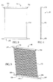
- Figure 1 is a schematic of a battery system having a battery module in accordance with an exemplary embodiment
- FIG. 2 is a schematic of the battery module utilized in the battery system of Figure 1 in accordance with another exemplary embodiment
- FIG 3 is a schematic of a cooling fin utilized in the battery system of Figure 1 ;
- Figure 4 is another schematic of the cooling fin of Figure 3 ;
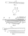
- FIG. 5 is another schematic of the cooling fin of Figure 3 illustrating the interior flow channels therein;
- Figure 6 is an enlarged schematic of a portion of a first header utilized in the cooling fin of Figure 3 ;
- FIG 7 is an enlarged schematic of a flow diverter utilized in the cooling fin of Figure 3 ;
- Figure 8 is a cross-sectional schematic of a portion of the cooling fin of Figure 3 ;
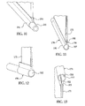
- Figure 9 is an enlarged schematic of an end portion of the cooling fin of Figure 3 illustrating the first header and a portion of an extruded housing;
- Figure 10 is an enlarged schematic of an end portion of the cooling fin of Figure 3 illustrating the first header and a portion of the extruded housing;
- FIG 11 is another enlarged schematic of an end portion of the cooling fin of Figure 3 illustrating the first header and a portion of the extruded housing;
- Figure 12 is another schematic of an end portion of the cooling fin of Figure 3 illustrating the first header and a portion of the extruded housing;
- Figure 13 is an enlarged schematic of an end portion of the cooling fin of Figure 3 illustrating a second header and a portion of the extruded housing;
- Figure 14 is a schematic of an end portion of the cooling fin of Figure 3 illustrating the second header and a portion of the extruded housing;
- Figure 15 is a schematic of an end cap member utilized in the second header
- Figure 16 is a flowchart of a method for cooling a battery module in accordance with another exemplary embodiment.
- Figure 17 is a schematic of another battery system in accordance with another exemplary embodiment.
- the battery system 10 includes a battery module 20, a compressor 22, a condenser 24, conduits 28, 30, 32, a temperature sensor 36, a fan 38, and a microprocessor 40.
- An advantage of the battery module 20 is that the battery module utilizes cooling fins with extruded housings to transfer heat energy from battery cells to the cooling fins to effectively cool the battery cells. Further, an advantage of an extruded housing is that the extruded housing can be easily brazed or welded to two headers to more easily manufacture a cooling fin, as compared to other devices.
- fluid means either a liquid or a gas.
- a fluid can comprise either a coolant or a refrigerant.
- coolants include ethylene glycol and propylene glycol.
- refrigerants include R-11, R-12, R-22, R-134A, R-407C and R-410A.
- the battery module 20 is provided to generate a voltage therein.
- the battery module 20 includes battery cells 60, 62, 64, 66, 68, 70, 72, 74, 76, 78, 80, 82 and cooling fins 90, 92, 94, 96, 98, 100, 102, 104, 106, 108, 110, 112.
- the battery cells 60, 62, 64, 66, 68, 70, 72, 74, 76, 78, 80, 82 are provided to generate an electrical voltage.
- each of the battery cells has a substantially similar structure.
- the battery cell includes a body portion 150, flange portions 152, 154, and electrodes 156, 158 extending upwardly from the body portion 150.
- the flange portions 152, 154 extend from first and second ends of the body portion 150.
- the electrodes 156, 158 have a voltage generated therebetween.
- the electrodes of the battery cells can be electrically coupled together either in series or in parallel depending upon a desired voltage and current of the battery module 20.
- each battery cell is a lithium-ion battery cell
- the battery cells could be nickel-cadmium battery cells or nickel metal hydride battery cells for example.
- other types of battery cells known to those skilled in the art could be utilized,
- the cooling fins 90, 92, 94, 96, 98, 100, 102, 104, 106, 108, 110, 112 are provided to conduct heat energy from the battery cells into the cooling fins.
- Each of the cooling fins has an inlet port fluidly coupled to the conduit 28. Further each of the cooling fans has an outlet port fluidly coupled to the conduit 30.
- the cooling fin 90 is disposed between the battery cells 60, 62, and the cooling fin 92 is disposed between the battery cells 62, 64.
- the cooling fin 94 is disposed between the battery cells 64, 66, and the cooling fm 96 is disposed between the battery cells 66, 68.
- the cooling fin 98 is disposed between the battery cells 68, 70, and the cooling fin 100 is disposed between the battery cells 70, 72.
- the cooling fin 102 is disposed between the battery cells 72, 74, and the cooling fin 104 is disposed between the battery cells 74, 76.
- the cooling fin 106 is disposed between the battery cells 76, 78, and the cooling fin 108 is disposed between the battery cells 78, 80.
- the cooling fin 108 is disposed between the battery cells 78, 80, and the cooling fin 110 is disposed between the battery cells 80, 82. Further, the cooling fin 112 is disposed adjacent to the battery cell 82.
- the cooling fins are constructed from at least one of aluminum and copper. During operation, the cooling fins are configured to receive a fluid from the compressor 22.
- the cooling fins conduct heat energy from the battery cells into the fluid flowing therethrough to cool the battery cells.
- the fluid is a coolant such as ethylene glycol or propylene glycol for example.
- the fluid is a refrigerant.
- the cooling fan 90 includes a header 170, an extruded housing 172, and a header 174.
- the header 170 includes a tubular portion 190, an extension portion 194, an inlet port 198, an outlet port 200, a flow diverter 202, and plugs 204,206.
- the tubular portion 190 includes an interior region 207 extending therethrough and the extension portion 194 includes an interior region 208 extending therethrough.
- the extension portion 194 is coupled to the tubular portion 190 and has a substantially similar length as the tubular portion 190. Further, the interior region 207 of the tubular portion 190 communicates with the interior region 208 of the extension portion 194. Further, the tubular portion 190 and the extension portion 194 are constructed from at least one of copper and aluminum.
- the inlet port 198 has a diameter smaller than the diameter of the tubular portion 190 and is disposed within a first end of the tubular portion 190.
- the inlet port 198 is brazed or welded to the tubular portion 190, and is constructed from at least one of copper and aluminum.
- the outlet port 200 has a diameter smaller than a diameter of the tubular portion 190 and is disposed within a second end of the tubular portion 190,
- the outlet port 200 is brazed or welded to the tubular portion 190, and is constructed from at least one of copper and aluminum.
- the flow diverter 202 is configured be disposed inside the interior regions 207, 208 of the tubular portion 190 and the extension portion 194, respectively, at a predetermined position such that fluid flows from the header 170 through a first plurality of flow channels to the header 174.
- the flow diverter 202 includes a circular-shaped plate 203 coupled to a rectangular-shaped plate 205.
- the circular-shaped plate 203 is configured to be disposed within the interior region 207 of the tubular portion 190.
- the rectangular-shaped plate 205 is configured to be disposed within the interior region 208 of the extension portion 194.
- the flow diverter 202 is constructed from at least one of copper and aluminum.
- the extruded housing 172 is provided to allow fluid to flow therethrough between the headers 170, 174 to remove heat energy from adjacent battery cells.
- the extruded housing 172 is a generally rectangular-shaped plate having a plurality of flow channels 220, 222, 224, 226, 228, 230, 232, 234, 236, 238, 240, 242, 244, 246, 248, 250, 252, 254, 256, 258, 260, 262, 264, 266, 268, 270, 272, 274, 276, 278, 280, 282, 284, 286, 288, 290, 292 extending therethrough.
- an end of the extruded housing 172 is configured to disposed within a portion of the extension portion 194 of the header 170, such that a first end of the flow channels fluidly communicate with the interior regions 207, 208 of the header 170.
- the extruded housing 172 is constructed from at least one of copper and aluminum, and is brazed or welded to the extension portion 194.
- the plugs 204, 206 are configured to be disposed at first and second ends, respectively, of the header 170 in the interior region 208 of the extension portion 194 to seal an end portion of the extension portion 194. Further, the plugs 204, 206 are disposed on opposite sides of the extruded housing 172 in the interior region 208.
- the plugs 204, 206 are constructed from at least one of copper and aluminum, and are brazed or welded to the extension portion 194.
- the header 174 includes a tubular portion 310, an extension portion 311, and end caps 312, 314.
- the tubular portion 310 includes an interior region 320 extending therethrough, and the extension portion 311 includes an interior region 322 extending therethrough.
- the extension portion 311 is coupled to the tubular portion 310 and has a substantially similar length as the tubular portion 310. Further, the interior region 320 of the tubular portion 310 communicates with the interior region 322 of the extension portion 311. Further, the tubular portion 310 and the extension portion 311 are constructed from at least one of copper and aluminum.
- the rectangular-shaped plate 205 of the extruded housing 172 is configured to be disposed at a second end within the interior region 322 of the extension portion 311, such that the flow channels 220, 222, 224, 226, 228, 230, 232, 234, 236, 238, 240, 242, 244, 246, 248, 250, 252, 254, 256, 258, 260, 262, 264, 266, 268, 270, 272, 274, 276, 278, 280, 282, 284, 286, 288, 290, 292 of the extruded housing 172 fluidly communicate with the interior regions 322, 320.
- the end caps 312, 314 are configured to be coupled to first and second ends, respectively, of the tubular portion 310 and the extension portion 311 to seal the first and second ends of the header 174.
- the end caps 312, 314 are constructed from at least one of copper and aluminum, and are brazed or welded to the tubular portion 310 and the extension portion 311.
- the configuration of the end caps 312, 314 are identical to one another. Accordingly, only the structure of the end cap 312 will be described in greater detail below, Referring to Figure 15 , the end cap 312 includes an inner circular-shaped portion 324 coupled to an inner T-shaped portion 326.
- the inner circular-shaped portion 324 and the inner T-shaped 326 are configured to be disposed in the interior regions 320, 322, respectively to seal one end of the header 174.
- the end cap 312 further includes an outer circular-shaped portion 327 and an outer rectangular-shaped portion 328 coupled to the inner circular-shaped portion 324 and the inner T-shaped portion 326, respectively.
- the outer circular-shaped portion 327 and the outer rectangular-shaped portion 328 are brazed or welded to an end of the tubular portion 310 and the extension portion 311.
- fluid is received into the inlet port 198 of the header 170 and is routed to a first plurality of flow channels including flow channels 220, 222, 224, 226, 228, 230, 232, 234, 236, 238,240, 242, 244, 246, 248, 250, 252, 254, 256, 258, 260, 262, 264, 266, 268, 270, 272, 274 of the extruded housing 172 when the flow diverter 202 is disposed in the header 170 proximate to the flow channel 274.
- the fluid flows through the first plurality of flow channels to the interior regions 320, 322 of the header 174 and extracts heat energy from the cooling fin and the adjacent battery cells into the fluid. Then, the fluid is routed through the header 174 and further through a second plurality of flow channels 276, 278, 280, 282, 284, 286, 288, 290 and 292 back to the header 170 that further extracts heat energy from the cooling fin and battery cells. Thereafter, the fluid is routed out of the outlet port 200. It should be noted that a number of flow channels in the first plurality of flow channels is greater than a number of flow channels in the second plurality of flow channels
- the cooling fins 90, 92, 94, 96, 98, 100, 102, 104, 106, 108, 110 and 112 maintain the battery cells within a desired temperature range, and in particular can maintain the battery cells at a temperature less than a threshold temperature level.
- the desired temperature range is 15° Celsius - 35° Celsius.
- the threshold temperature level is 40° Celsius.
- the compressor 22 is configured to pump a refrigerant through the conduit 28 into inlet ports of the battery module 20 in response to a control signal from the microprocessor 40.
- the conduit 30 is also fluidly coupled to outlet ports of the battery module 20. The conduit 30 receives refrigerant from the outlet ports and routes the refrigerant to the condenser 24.
- the condenser 24 is provided to extract heat energy from the refrigerant flowing therethrough to cool the refrigerant. As shown, a conduit 32 is fluidly coupled between the condenser 24 and the compressor 22. After exiting the condenser 24, the refrigerant is pumped through the conduit 32 to the compressor 22.
- the temperature sensor 36 is provided to generate a signal indicative of a temperature level of the battery cells disposed in the housing 60 that is received by the microprocessor 40.
- the fan 38 is provided to urge air past the condenser 24 to cool the condenser 24 in response to a control signal from the microprocessor 40. As shown, the fan 38 is disposed proximate to the condenser 24.
- the microprocessor 40 is provided to control operation of the battery system 10.
- the microprocessor 40 is configured to generate a control signal for inducing the compressor 22 to pump refrigerant through the battery module 20 when the signal from the temperature sensor 36 indicates a temperature level of the battery cells is greater than a predetermined temperature level.
- the microprocessor 40 is configured to generate another control signal for inducing the fan 38 to blow air across the condenser 24 when the signal from the temperature sensor 36 indicates the temperature level of the battery cells is greater than the predetermined temperature level.
- the cooling fin 90 has headers 170, 174, the extruded housing 172, and the flow diverter 202.
- the header 170 receives a fluid that is diverted by the flow diverter 202 in the header 170 through a first plurality of flow channels in the extruded housing 172 to the header 174 to extract heat energy from the cooling fin 90.
- the fluid is routed from the header 174 through a second plurality of flow channels in the extruded housing 172 back to the header 170 that further extracts heat energy from the cooling fin 90.
- the battery system 410 includes a battery module 420, a pump 422, a heat exchanger 424, a cold plate 425, a reservoir 426, conduits 428, 430, 431, 432, 434, a temperature sensor 436, a fan 437, a refrigerant system 438, and a microprocessor 440.
- the primary difference between the battery system 410 and the battery system 10 is that the battery system 410 utilizes a coolant instead of a refrigerant to cool the battery module 420.
- the battery module 420 has an identical structure as the battery module 20 discussed above.
- the pump 422 is configured to pump a coolant through the conduit 428 into inlet ports of the battery module 420 in response to a control signal from the microprocessor 440.
- the conduit 428 is fluidly coupled between the pump 422 and the battery module 420
- the conduit 430 is fluidly coupled between the battery module 420 and the heat exchanger 424. After exiting the outlet ports of the battery module 420, the coolant is pumped through the conduit 430 to the heat exchanger 424.
- the heat exchanger 424 is provided to extract heat energy from the coolant flowing therethrough to cool the coolant.
- a conduit 431 is fluidly coupled between the heat exchanger 424 and the cold plate 425. After exiting the heat exchanger 424, the coolant is pumped through the conduit 431 to the cold plate 425.
- the fan 437 is provided to urge air past the heat exchanger 424 to cool the heat exchanger 424 in response to a control signal from the microprocessor 440. As shown, the fan 437 is disposed proximate to the heat exchanger 424.
- the cold plate 425 is provided to extract heat energy from the coolant flowing therethrough to further cool the coolant.
- a conduit 422 is fluidly coupled between the cold plate 425 and the reservoir 426. After exiting the cold plate 425, the coolant is pumped through the conduit 432 to the reservoir 426.
- the reservoir 426 is provided to store at least a portion of the coolant therein, As shown, a conduit 434 is fluidly coupled between the reservoir 426 and the pump 422. After exiting the reservoir 426, the coolant is pumped through the conduit 434 to the pump 422.
- the temperature sensor 436 is provided to generate a signal indicative of a temperature level of at least one of the battery cells in the battery module 420, that is received by the microprocessor 440.
- the refrigerant system 438 is provided to cool the heat exchanger 424 in response to a control signal from the microprocessor 440. As shown, the refrigerant system 438 is operably coupled to the cold plate 425.
- the microprocessor 440 is provided to control operation of the battery system 410.
- the microprocessor 440 is configured to generate a control signal for inducing the pump 422 to pump refrigerant through the battery module 420 when the signal from the temperature sensor 436 indicates a temperature level of at least one of the battery cells is greater than a predetermined temperature level.
- the microprocessor 440 is configured to generate another control signal for inducing the fan 437 to blow air across the heat exchanger 424 when the signal from the temperature sensor 436 indicates the temperature level of at least one of the battery cells is greater than the predetermined temperature level.
- microprocessor 440 is configured to generate another control signal for inducing the refrigerant system 438 to cool the cold plate 425 when the signal from the temperature sensor 436 indicates the temperature level of at least one of the battery cells is greater than the predetermined temperature level.
- the battery module and the method for cooling the battery module provide a substantial advantage over other modules and methods.
- the battery module and the method provide a technical effect of cooling a battery cell in the battery module utilizing a cooling fin with an extruded manifold which can be easily assembled and manufacture.
Landscapes
- Engineering & Computer Science (AREA)
- Chemical & Material Sciences (AREA)
- Chemical Kinetics & Catalysis (AREA)
- Electrochemistry (AREA)
- General Chemical & Material Sciences (AREA)
- Manufacturing & Machinery (AREA)
- Combustion & Propulsion (AREA)
- Physics & Mathematics (AREA)
- Mechanical Engineering (AREA)
- Thermal Sciences (AREA)
- General Engineering & Computer Science (AREA)
- Secondary Cells (AREA)
- Battery Mounting, Suspending (AREA)
Abstract
Description
- This application relates to a battery module and a method for cooling the battery module.
- In a typical air-cooled battery pack, ambient air from ambient atmosphere is directed across battery cells in the battery pack and is subsequently exhausted from the battery pack. However, the typical air-cooled battery pack has a major challenge in maintaining a temperature of the battery pack within a desired temperature range.
- In particular, a maximum operating temperature of the battery cells can often be less than a temperature of ambient air utilized to cool the batteries. In this situation, it is impossible to maintain the battery cells within a desired temperature range in an air-cooled battery pack.
- Accordingly, the inventors herein have recognized a need for an improved battery module and a method for cooling the battery module that minimizes and/or eliminates the above-mentioned deficiency.
- A battery module in accordance with an exemplary embodiment is provided. The battery module includes a first battery cell and a cooling fin. The cooling fin is disposed adjacent to the first battery cell. The cooling fin has first and second headers, an extruded housing, and a flow diverter. The first and second headers are coupled to first and second ends, respectively, of the extruded housing. The extruded housing has a first plurality of flow channels and a second plurality of flow channels extending therethrough that fluidly communicate with the first and second headers. The flow diverter is disposed in the first header to induce a fluid to flow from the first header through the first plurality of flow channels in the extruded housing to the second header to extract heat energy from the first battery cell. The flow diverter further induces the fluid to flow from the second header through the second plurality of flow channels in the extruded housing back to the first header to further extract heat energy from the first battery cell.
- A method for cooling a battery module in accordance with another exemplary embodiment is provided. The battery module has a first battery cell and a cooling fin disposed adjacent to the first battery cell. The cooling fin has first and second headers, an extruded housing, and a flow diverter. The first and second headers are coupled to first and second ends, respectively, of the extruded housing. The extruded housing has a first plurality of flow channels and a second plurality of flow channels extending therethrough that fluidly communicate with the first and second headers. The flow diverter is disposed in the first header. The method includes conducting heat energy from the first battery cell into the cooling fin. The method further includes receiving a fluid into the first header that is diverted by a flow diverter in the first header through the first plurality of flow channels in the extruded housing to the second header to extract heat energy from the cooling fin. The method further includes routing the fluid from the second header through the second plurality of flow channels in the extruded housing back to the first header which further extracts heat energy from the cooling fin.
-
Figure 1 is a schematic of a battery system having a battery module in accordance with an exemplary embodiment; -
Figure 2 is a schematic of the battery module utilized in the battery system ofFigure 1 in accordance with another exemplary embodiment; -
Figure 3 is a schematic of a cooling fin utilized in the battery system ofFigure 1 ; -
Figure 4 is another schematic of the cooling fin ofFigure 3 ; -
Figure 5 is another schematic of the cooling fin ofFigure 3 illustrating the interior flow channels therein; -
Figure 6 is an enlarged schematic of a portion of a first header utilized in the cooling fin ofFigure 3 ; -
Figure 7 is an enlarged schematic of a flow diverter utilized in the cooling fin ofFigure 3 ; -
Figure 8 is a cross-sectional schematic of a portion of the cooling fin ofFigure 3 ; -
Figure 9 is an enlarged schematic of an end portion of the cooling fin ofFigure 3 illustrating the first header and a portion of an extruded housing; -
Figure 10 is an enlarged schematic of an end portion of the cooling fin ofFigure 3 illustrating the first header and a portion of the extruded housing; -
Figure 11 is another enlarged schematic of an end portion of the cooling fin ofFigure 3 illustrating the first header and a portion of the extruded housing; -
Figure 12 is another schematic of an end portion of the cooling fin ofFigure 3 illustrating the first header and a portion of the extruded housing; -
Figure 13 is an enlarged schematic of an end portion of the cooling fin ofFigure 3 illustrating a second header and a portion of the extruded housing; -
Figure 14 is a schematic of an end portion of the cooling fin ofFigure 3 illustrating the second header and a portion of the extruded housing; -
Figure 15 is a schematic of an end cap member utilized in the second header; -
Figure 16 is a flowchart of a method for cooling a battery module in accordance with another exemplary embodiment; and -
Figure 17 is a schematic of another battery system in accordance with another exemplary embodiment. - Referring to
Figure 1 , abattery system 10 for generating electrical power in accordance with an exemplary embodiment is illustrated. Thebattery system 10 includes abattery module 20, acompressor 22, acondenser 24,conduits temperature sensor 36, afan 38, and amicroprocessor 40. An advantage of thebattery module 20 is that the battery module utilizes cooling fins with extruded housings to transfer heat energy from battery cells to the cooling fins to effectively cool the battery cells. Further, an advantage of an extruded housing is that the extruded housing can be easily brazed or welded to two headers to more easily manufacture a cooling fin, as compared to other devices. - For purposes of understanding, the term "fluid" means either a liquid or a gas. For example, a fluid can comprise either a coolant or a refrigerant. Exemplary coolants include ethylene glycol and propylene glycol. Exemplary refrigerants include R-11, R-12, R-22, R-134A, R-407C and R-410A.
- Referring to
Figures 1 and 2 , thebattery module 20 is provided to generate a voltage therein. Thebattery module 20 includesbattery cells cooling fins - The
battery cells battery cell 60, the battery cell includes abody portion 150,flange portions electrodes 156, 158 extending upwardly from thebody portion 150. Theflange portions body portion 150. Theelectrodes 156, 158 have a voltage generated therebetween. The electrodes of the battery cells can be electrically coupled together either in series or in parallel depending upon a desired voltage and current of thebattery module 20. In one exemplary embodiment, each battery cell is a lithium-ion battery cell, In alternative embodiments, the battery cells could be nickel-cadmium battery cells or nickel metal hydride battery cells for example. Of course, other types of battery cells known to those skilled in the art could be utilized, - The cooling fins 90, 92, 94, 96, 98, 100, 102, 104, 106, 108, 110, 112 are provided to conduct heat energy from the battery cells into the cooling fins. Each of the cooling fins has an inlet port fluidly coupled to the
conduit 28. Further each of the cooling fans has an outlet port fluidly coupled to theconduit 30. The coolingfin 90 is disposed between thebattery cells fin 92 is disposed between thebattery cells fin 94 is disposed between thebattery cells cooling fm 96 is disposed between thebattery cells fin 98 is disposed between thebattery cells fin 100 is disposed between thebattery cells fin 102 is disposed between thebattery cells fin 104 is disposed between thebattery cells fin 106 is disposed between thebattery cells fin 108 is disposed between thebattery cells fin 108 is disposed between thebattery cells fin 110 is disposed between thebattery cells fin 112 is disposed adjacent to thebattery cell 82. The cooling fins are constructed from at least one of aluminum and copper. During operation, the cooling fins are configured to receive a fluid from thecompressor 22. The cooling fins conduct heat energy from the battery cells into the fluid flowing therethrough to cool the battery cells. In one exemplary embodiment, the fluid is a coolant such as ethylene glycol or propylene glycol for example. In another exemplary embodiment, the fluid is a refrigerant. - The structure of the cooling fins are identical to one another. Accordingly, only the structure of the cooling
fin 90 will be explained in greater detail. Referring toFigures 3, 4 and 5 , the coolingfan 90 includes aheader 170, anextruded housing 172, and aheader 174. - Referring to
Figures 6 and8-11 , theheader 170 includes atubular portion 190, anextension portion 194, aninlet port 198, anoutlet port 200, aflow diverter 202, and plugs 204,206. - The
tubular portion 190 includes aninterior region 207 extending therethrough and theextension portion 194 includes aninterior region 208 extending therethrough. Theextension portion 194 is coupled to thetubular portion 190 and has a substantially similar length as thetubular portion 190. Further, theinterior region 207 of thetubular portion 190 communicates with theinterior region 208 of theextension portion 194. Further, thetubular portion 190 and theextension portion 194 are constructed from at least one of copper and aluminum. - The
inlet port 198 has a diameter smaller than the diameter of thetubular portion 190 and is disposed within a first end of thetubular portion 190. Theinlet port 198 is brazed or welded to thetubular portion 190, and is constructed from at least one of copper and aluminum. - The
outlet port 200 has a diameter smaller than a diameter of thetubular portion 190 and is disposed within a second end of thetubular portion 190, Theoutlet port 200 is brazed or welded to thetubular portion 190, and is constructed from at least one of copper and aluminum. - Referring to
Figures 7 ,11 and 12 , theflow diverter 202 is configured be disposed inside theinterior regions tubular portion 190 and theextension portion 194, respectively, at a predetermined position such that fluid flows from theheader 170 through a first plurality of flow channels to theheader 174. Theflow diverter 202 includes a circular-shapedplate 203 coupled to a rectangular-shapedplate 205. In particular, the circular-shapedplate 203 is configured to be disposed within theinterior region 207 of thetubular portion 190. The rectangular-shapedplate 205 is configured to be disposed within theinterior region 208 of theextension portion 194. Further, theflow diverter 202 is constructed from at least one of copper and aluminum. - Referring to
Figures 5 ,8 ,9 and11 , the extrudedhousing 172 is provided to allow fluid to flow therethrough between theheaders housing 172 is a generally rectangular-shaped plate having a plurality offlow channels housing 172 is configured to disposed within a portion of theextension portion 194 of theheader 170, such that a first end of the flow channels fluidly communicate with theinterior regions header 170. The extrudedhousing 172 is constructed from at least one of copper and aluminum, and is brazed or welded to theextension portion 194. - Referring to
Figures 9 and10 , theplugs header 170 in theinterior region 208 of theextension portion 194 to seal an end portion of theextension portion 194. Further, theplugs housing 172 in theinterior region 208. Theplugs extension portion 194. - Referring to
Figures 5 ,13 and14 , theheader 174 includes atubular portion 310, anextension portion 311, and endcaps - The
tubular portion 310 includes aninterior region 320 extending therethrough, and theextension portion 311 includes aninterior region 322 extending therethrough. Theextension portion 311 is coupled to thetubular portion 310 and has a substantially similar length as thetubular portion 310. Further, theinterior region 320 of thetubular portion 310 communicates with theinterior region 322 of theextension portion 311. Further, thetubular portion 310 and theextension portion 311 are constructed from at least one of copper and aluminum. The rectangular-shapedplate 205 of the extrudedhousing 172 is configured to be disposed at a second end within theinterior region 322 of theextension portion 311, such that theflow channels housing 172 fluidly communicate with theinterior regions - The end caps 312, 314 are configured to be coupled to first and second ends, respectively, of the
tubular portion 310 and theextension portion 311 to seal the first and second ends of theheader 174. The end caps 312, 314 are constructed from at least one of copper and aluminum, and are brazed or welded to thetubular portion 310 and theextension portion 311. The configuration of the end caps 312, 314 are identical to one another. Accordingly, only the structure of theend cap 312 will be described in greater detail below, Referring toFigure 15 , theend cap 312 includes an inner circular-shapedportion 324 coupled to an inner T-shapedportion 326. The inner circular-shapedportion 324 and the inner T-shaped 326 are configured to be disposed in theinterior regions header 174. Theend cap 312 further includes an outer circular-shapedportion 327 and an outer rectangular-shapedportion 328 coupled to the inner circular-shapedportion 324 and the inner T-shapedportion 326, respectively. The outer circular-shapedportion 327 and the outer rectangular-shapedportion 328 are brazed or welded to an end of thetubular portion 310 and theextension portion 311. - Referring to
Figures 5 and8 , during operation, in one exemplary embodiment, fluid is received into theinlet port 198 of theheader 170 and is routed to a first plurality of flow channels includingflow channels housing 172 when theflow diverter 202 is disposed in theheader 170 proximate to the flow channel 274. Then, the fluid flows through the first plurality of flow channels to theinterior regions header 174 and extracts heat energy from the cooling fin and the adjacent battery cells into the fluid. Then, the fluid is routed through theheader 174 and further through a second plurality offlow channels header 170 that further extracts heat energy from the cooling fin and battery cells. Thereafter, the fluid is routed out of theoutlet port 200. It should be noted that a number of flow channels in the first plurality of flow channels is greater than a number of flow channels in the second plurality of flow channels - The cooling
fins - Referring again to
Figure 1 , in one exemplary embodiment, thecompressor 22 is configured to pump a refrigerant through theconduit 28 into inlet ports of thebattery module 20 in response to a control signal from themicroprocessor 40. Theconduit 30 is also fluidly coupled to outlet ports of thebattery module 20. Theconduit 30 receives refrigerant from the outlet ports and routes the refrigerant to thecondenser 24. - The
condenser 24 is provided to extract heat energy from the refrigerant flowing therethrough to cool the refrigerant. As shown, aconduit 32 is fluidly coupled between thecondenser 24 and thecompressor 22. After exiting thecondenser 24, the refrigerant is pumped through theconduit 32 to thecompressor 22. - The
temperature sensor 36 is provided to generate a signal indicative of a temperature level of the battery cells disposed in thehousing 60 that is received by themicroprocessor 40. - The
fan 38 is provided to urge air past thecondenser 24 to cool thecondenser 24 in response to a control signal from themicroprocessor 40. As shown, thefan 38 is disposed proximate to thecondenser 24. - The
microprocessor 40 is provided to control operation of thebattery system 10. In particular, themicroprocessor 40 is configured to generate a control signal for inducing thecompressor 22 to pump refrigerant through thebattery module 20 when the signal from thetemperature sensor 36 indicates a temperature level of the battery cells is greater than a predetermined temperature level. Further, themicroprocessor 40 is configured to generate another control signal for inducing thefan 38 to blow air across thecondenser 24 when the signal from thetemperature sensor 36 indicates the temperature level of the battery cells is greater than the predetermined temperature level. - Referring to
Figure 16 , a flowchart of a method for cooling thebattery module 20 having a battery cell will now be explained. For purposes of simplicity, only one battery cell and one coo ling fin will be described. - At
step 350, heat energy is conducted from thebattery cell 60 into the coolingfin 90. The coolingfin 90 hasheaders housing 172, and theflow diverter 202. - At
step 352, theheader 170 receives a fluid that is diverted by theflow diverter 202 in theheader 170 through a first plurality of flow channels in the extrudedhousing 172 to theheader 174 to extract heat energy from the coolingfin 90. - At
step 354, the fluid is routed from theheader 174 through a second plurality of flow channels in the extrudedhousing 172 back to theheader 170 that further extracts heat energy from the coolingfin 90. - Referring to
Figure 17 , abattery system 410 for generating electrical power in accordance with another exemplary embodiment is illustrated, Thebattery system 410 includes abattery module 420, apump 422, aheat exchanger 424, acold plate 425, areservoir 426,conduits temperature sensor 436, afan 437, arefrigerant system 438, and amicroprocessor 440. The primary difference between thebattery system 410 and thebattery system 10 is that thebattery system 410 utilizes a coolant instead of a refrigerant to cool thebattery module 420. - The
battery module 420 has an identical structure as thebattery module 20 discussed above. - The
pump 422 is configured to pump a coolant through theconduit 428 into inlet ports of thebattery module 420 in response to a control signal from themicroprocessor 440. As shown, theconduit 428 is fluidly coupled between thepump 422 and thebattery module 420, and theconduit 430 is fluidly coupled between thebattery module 420 and theheat exchanger 424. After exiting the outlet ports of thebattery module 420, the coolant is pumped through theconduit 430 to theheat exchanger 424. - The
heat exchanger 424 is provided to extract heat energy from the coolant flowing therethrough to cool the coolant. As shown, aconduit 431 is fluidly coupled between theheat exchanger 424 and thecold plate 425. After exiting theheat exchanger 424, the coolant is pumped through theconduit 431 to thecold plate 425. - The
fan 437 is provided to urge air past theheat exchanger 424 to cool theheat exchanger 424 in response to a control signal from themicroprocessor 440. As shown, thefan 437 is disposed proximate to theheat exchanger 424. - The
cold plate 425 is provided to extract heat energy from the coolant flowing therethrough to further cool the coolant. As shown, aconduit 422 is fluidly coupled between thecold plate 425 and thereservoir 426. After exiting thecold plate 425, the coolant is pumped through theconduit 432 to thereservoir 426. - The
reservoir 426 is provided to store at least a portion of the coolant therein, As shown, aconduit 434 is fluidly coupled between thereservoir 426 and thepump 422. After exiting thereservoir 426, the coolant is pumped through theconduit 434 to thepump 422. - The
temperature sensor 436 is provided to generate a signal indicative of a temperature level of at least one of the battery cells in thebattery module 420, that is received by themicroprocessor 440. - The
refrigerant system 438 is provided to cool theheat exchanger 424 in response to a control signal from themicroprocessor 440. As shown, therefrigerant system 438 is operably coupled to thecold plate 425. - The
microprocessor 440 is provided to control operation of thebattery system 410. In particular, themicroprocessor 440 is configured to generate a control signal for inducing thepump 422 to pump refrigerant through thebattery module 420 when the signal from thetemperature sensor 436 indicates a temperature level of at least one of the battery cells is greater than a predetermined temperature level. Further, themicroprocessor 440 is configured to generate another control signal for inducing thefan 437 to blow air across theheat exchanger 424 when the signal from thetemperature sensor 436 indicates the temperature level of at least one of the battery cells is greater than the predetermined temperature level. Further, themicroprocessor 440 is configured to generate another control signal for inducing therefrigerant system 438 to cool thecold plate 425 when the signal from thetemperature sensor 436 indicates the temperature level of at least one of the battery cells is greater than the predetermined temperature level. - The battery module and the method for cooling the battery module provide a substantial advantage over other modules and methods. In particular, the battery module and the method provide a technical effect of cooling a battery cell in the battery module utilizing a cooling fin with an extruded manifold which can be easily assembled and manufacture.
- While the invention has been described with reference to exemplary embodiments, it will be understood by those skilled in the art that various changes may be made and equivalents may be substituted for elements thereof without departing from the scope of the invention. In addition, many modifications may be made to adapt a particular situation or material to the teachings of the invention without departing from the essential scope thereof. Therefore, it is intended that the invention not be limited to the particular embodiments disclosed for carrying this invention, but that the invention will include all embodiments falling within the scope of the appended claims. Moreover, the use of the terms, first, second, etc. are used to distinguish one element from another. Further, the use of the terms a, an, etc. do not denote a limitation of quantity, but rather denote the presence of at least one of the referenced items.
Claims (13)
- A battery module, comprising:a first battery cell; anda cooling fin disposed adjacent to the first battery cell, the cooling fin having first and second headers, an extruded housing, and a flow diverter, the first and second headers coupled to first and second ends, respectively, of the extruded housing, the extruded housing having a first plurality of flow channels and a second plurality of flow channels extending therethrough that fluidly communicate with the first and second headers, the flow diverter being disposed in the first header to induce a fluid to flow from the first header through the first plurality of flow channels in the extruded housing to the second header to extract heat energy from the first battery cell, and then to induce the fluid to flow from the second header through the second plurality of flow channels in the extruded housing back to the first header to further extract heat energy from the first battery cell.
- The battery module of claim 1, wherein the first and second headers are generally tubular-shaped.
- The battery module of claim 1, wherein the first and second headers are constructed of at least one of copper and aluminum.
- The battery module of claim 1, wherein the extruded housing is constructed of at least one of copper and aluminum.
- The battery module of claim 1, wherein a number of flow channels in the first plurality of flow channels is greater than a number of flow channels in the second plurality of flow channels.
- The battery module of claim 1, wherein the fluid is a coolant.
- The battery module of claim 6, wherein the coolant comprises at least one of ethylene glycol and propylene glycol.
- The battery module of claim 1, wherein the fluid is a refrigerant.
- The battery module of claim 1, further comprising a second battery cell disposed adjacent to the cooling fin, such that the cooling fin is disposed between the first and second battery cells.
- A method for cooling a battery module, the battery module having a first battery cell and a cooling fin disposed adjacent to the first battery cell, the cooling fin having first and second headers, an extruded housing, and a flow diverter, the first and second headers coupied to first and second ends, respectively, of the extruded housing, the extruded housing having a first plurality of flow channels and a second plurality of flow channels extending therethrough that fluidly communicate with the first and second headers, the flow diverter being disposed in the first header, the method comprising:conducting heat energy from the first battery cell into the cooling fin;receiving a fluid into the first header that is diverted by a flow diverter in the first header through the first plurality of flow channels in the extruded housing to the second header to extract heat energy from the cooling fin; androuting the fluid from the second header through the second plurality of flow channels in the extruded housing back to the first header which further extracts heat energy from the cooling fin.
- The method of claim 10, wherein the fluid is a coolant.
- The method of claim 11, wherein the coolant comprises at least one of ethylene glycol and propylene glycol.
- The method of claim 10, wherein the fluid is a refrigerant.
Applications Claiming Priority (2)
| Application Number | Priority Date | Filing Date | Title |
|---|---|---|---|
| US12/511,530 US8399118B2 (en) | 2009-07-29 | 2009-07-29 | Battery module and method for cooling the battery module |
| PCT/KR2010/004944 WO2011013997A2 (en) | 2009-07-29 | 2010-07-28 | Battery module, and method for cooling a battery module |
Publications (3)
| Publication Number | Publication Date |
|---|---|
| EP2461417A2 true EP2461417A2 (en) | 2012-06-06 |
| EP2461417A4 EP2461417A4 (en) | 2013-11-20 |
| EP2461417B1 EP2461417B1 (en) | 2015-02-25 |
Family
ID=43527341
Family Applications (1)
| Application Number | Title | Priority Date | Filing Date |
|---|---|---|---|
| EP20100804710 Active EP2461417B1 (en) | 2009-07-29 | 2010-07-28 | Battery module, and method for cooling a battery module |
Country Status (6)
| Country | Link |
|---|---|
| US (1) | US8399118B2 (en) |
| EP (1) | EP2461417B1 (en) |
| JP (1) | JP5499168B2 (en) |
| KR (1) | KR101163385B1 (en) |
| CN (1) | CN102473979B (en) |
| WO (1) | WO2011013997A2 (en) |
Cited By (1)
| Publication number | Priority date | Publication date | Assignee | Title |
|---|---|---|---|---|
| DE102012217870A1 (en) * | 2012-09-28 | 2014-04-17 | Behr Gmbh & Co. Kg | Heat exchanger |
Families Citing this family (84)
| Publication number | Priority date | Publication date | Assignee | Title |
|---|---|---|---|---|
| US8703311B2 (en) * | 2008-03-05 | 2014-04-22 | Calsonic Kansei Corporation | Vehicle battery cooling device |
| US9140501B2 (en) | 2008-06-30 | 2015-09-22 | Lg Chem, Ltd. | Battery module having a rubber cooling manifold |
| US9759495B2 (en) | 2008-06-30 | 2017-09-12 | Lg Chem, Ltd. | Battery cell assembly having heat exchanger with serpentine flow path |
| US8067111B2 (en) * | 2008-06-30 | 2011-11-29 | Lg Chem, Ltd. | Battery module having battery cell assembly with heat exchanger |
| US9337456B2 (en) | 2009-04-20 | 2016-05-10 | Lg Chem, Ltd. | Frame member, frame assembly and battery cell assembly made therefrom and methods of making the same |
| US8852778B2 (en) | 2009-04-30 | 2014-10-07 | Lg Chem, Ltd. | Battery systems, battery modules, and method for cooling a battery module |
| US8663828B2 (en) | 2009-04-30 | 2014-03-04 | Lg Chem, Ltd. | Battery systems, battery module, and method for cooling the battery module |
| US8663829B2 (en) | 2009-04-30 | 2014-03-04 | Lg Chem, Ltd. | Battery systems, battery modules, and method for cooling a battery module |
| US8403030B2 (en) | 2009-04-30 | 2013-03-26 | Lg Chem, Ltd. | Cooling manifold |
| KR101130043B1 (en) * | 2009-07-27 | 2012-03-28 | 주식회사 엘지화학 | Battery Module of Improved Cooling Efficiency |
| US8399118B2 (en) | 2009-07-29 | 2013-03-19 | Lg Chem, Ltd. | Battery module and method for cooling the battery module |
| US8399119B2 (en) | 2009-08-28 | 2013-03-19 | Lg Chem, Ltd. | Battery module and method for cooling the battery module |
| DE102009040814A1 (en) * | 2009-09-10 | 2011-03-17 | Behr Gmbh & Co. Kg | Method for producing an energy storage holder for a vehicle |
| KR101205181B1 (en) * | 2010-05-18 | 2012-11-27 | 주식회사 엘지화학 | Cooling Member of Novel Structure and Battery Module Employed with the Same |
| US9203065B2 (en) | 2010-08-10 | 2015-12-01 | Samsung Sdi Co., Ltd. | Battery module |
| US8662153B2 (en) | 2010-10-04 | 2014-03-04 | Lg Chem, Ltd. | Battery cell assembly, heat exchanger, and method for manufacturing the heat exchanger |
| JP5777734B2 (en) * | 2011-02-22 | 2015-09-09 | エルジー ケム. エルティーディ. | Cooling member with improved cooling efficiency and battery module using the same |
| US8771382B2 (en) * | 2011-02-25 | 2014-07-08 | GM Global Technology Operations LLC | Heat shrink joining of battery cell components |
| US8288031B1 (en) | 2011-03-28 | 2012-10-16 | Lg Chem, Ltd. | Battery disconnect unit and method of assembling the battery disconnect unit |
| US9178192B2 (en) | 2011-05-13 | 2015-11-03 | Lg Chem, Ltd. | Battery module and method for manufacturing the battery module |
| TWI420725B (en) | 2011-07-18 | 2013-12-21 | Delta Electronics Inc | Battery device and battery device module |
| US9496544B2 (en) | 2011-07-28 | 2016-11-15 | Lg Chem. Ltd. | Battery modules having interconnect members with vibration dampening portions |
| US9761850B2 (en) * | 2011-10-28 | 2017-09-12 | Nucleus Scientific, Inc. | Multi-cell battery assembly |
| CN102544620B (en) * | 2011-11-30 | 2014-03-05 | 苏州新中能源科技有限公司 | Water-cooling device for lithium-ion power battery grouping |
| US9605914B2 (en) | 2012-03-29 | 2017-03-28 | Lg Chem, Ltd. | Battery system and method of assembling the battery system |
| US9105950B2 (en) * | 2012-03-29 | 2015-08-11 | Lg Chem, Ltd. | Battery system having an evaporative cooling member with a plate portion and a method for cooling the battery system |
| US9379420B2 (en) | 2012-03-29 | 2016-06-28 | Lg Chem, Ltd. | Battery system and method for cooling the battery system |
| EP2654120A1 (en) | 2012-04-20 | 2013-10-23 | Magna E-Car Systems GmbH & Co OG | Device for cooling a vehicle battery |
| KR101971512B1 (en) | 2012-05-04 | 2019-04-23 | 에스케이이노베이션 주식회사 | The Battery Module and Manufacturing method for same |
| US8852781B2 (en) | 2012-05-19 | 2014-10-07 | Lg Chem, Ltd. | Battery cell assembly and method for manufacturing a cooling fin for the battery cell assembly |
| US9306199B2 (en) | 2012-08-16 | 2016-04-05 | Lg Chem, Ltd. | Battery module and method for assembling the battery module |
| US20140120390A1 (en) * | 2012-10-31 | 2014-05-01 | Lg Chem, Ltd. | Battery cell assembly and method for manufacturing a cooling fin for the battery cell assembly |
| US9083066B2 (en) * | 2012-11-27 | 2015-07-14 | Lg Chem, Ltd. | Battery system and method for cooling a battery cell assembly |
| US8852783B2 (en) | 2013-02-13 | 2014-10-07 | Lg Chem, Ltd. | Battery cell assembly and method for manufacturing the battery cell assembly |
| US9647292B2 (en) | 2013-04-12 | 2017-05-09 | Lg Chem, Ltd. | Battery cell assembly and method for manufacturing a cooling fin for the battery cell assembly |
| DE102013104151B4 (en) * | 2013-04-24 | 2024-05-16 | Dr. Ing. H.C. F. Porsche Aktiengesellschaft | Cooling device with a cooling block and method for producing such a cooling device |
| EP2804251B1 (en) | 2013-04-24 | 2016-07-20 | Samsung SDI Co., Ltd. | Vehicle battery system |
| US9184424B2 (en) | 2013-07-08 | 2015-11-10 | Lg Chem, Ltd. | Battery assembly |
| US10062934B2 (en) | 2013-07-25 | 2018-08-28 | Johnson Controls Technology Company | Cooling system and method for lithium-ion battery module |
| DE102013215358A1 (en) * | 2013-08-05 | 2015-02-19 | Behr Gmbh & Co. Kg | Heat exchanger for cooling a vehicle battery, in particular for hybrid or electric vehicles |
| US9123949B2 (en) | 2013-09-17 | 2015-09-01 | Lg Chem, Ltd. | Battery module and battery cell |
| US9123950B2 (en) | 2013-09-26 | 2015-09-01 | Lg Chem, Ltd. | Battery module and battery cell |
| US9257732B2 (en) | 2013-10-22 | 2016-02-09 | Lg Chem, Ltd. | Battery cell assembly |
| EP2879278B1 (en) * | 2013-11-27 | 2017-06-28 | Skf Magnetic Mechatronics | Versatile cooling housing for an electrical motor |
| US9444124B2 (en) | 2014-01-23 | 2016-09-13 | Lg Chem, Ltd. | Battery cell assembly and method for coupling a cooling fin to first and second cooling manifolds |
| US20150211805A1 (en) * | 2014-01-29 | 2015-07-30 | Kunshan Jue-Chung Electronics Co., Ltd. | Thermostat module |
| US9452683B2 (en) | 2014-02-25 | 2016-09-27 | Ford Global Technologies, Llc | Traction battery thermal plate with longitudinal channel configuration |
| US10396411B2 (en) | 2014-02-25 | 2019-08-27 | Ford Global Technologies, Llc | Traction battery thermal plate with transverse channel configuration |
| US9368845B2 (en) * | 2014-02-25 | 2016-06-14 | Ford Global Technologies, Llc | Traction battery thermal plate with multi pass channel configuration |
| US9172122B2 (en) * | 2014-02-25 | 2015-10-27 | Lg Chem, Ltd. | Battery module |
| US10084218B2 (en) | 2014-05-09 | 2018-09-25 | Lg Chem, Ltd. | Battery pack and method of assembling the battery pack |
| US10770762B2 (en) | 2014-05-09 | 2020-09-08 | Lg Chem, Ltd. | Battery module and method of assembling the battery module |
| DE102014217546A1 (en) | 2014-09-03 | 2016-03-03 | Robert Bosch Gmbh | Cooling and / or heating device of a battery module |
| US10658717B2 (en) | 2014-09-30 | 2020-05-19 | Cps Technology Holdings Llc | Battery module active thermal management features and positioning |
| US10720683B2 (en) | 2014-09-30 | 2020-07-21 | Cps Technology Holdings Llc | Battery module thermal management features for internal flow |
| US9825343B2 (en) | 2014-09-30 | 2017-11-21 | Johnson Controls Technology Company | Battery module passive thermal management features and positioning |
| US9484559B2 (en) | 2014-10-10 | 2016-11-01 | Lg Chem, Ltd. | Battery cell assembly |
| US9412980B2 (en) | 2014-10-17 | 2016-08-09 | Lg Chem, Ltd. | Battery cell assembly |
| US9786894B2 (en) | 2014-11-03 | 2017-10-10 | Lg Chem, Ltd. | Battery pack |
| US9627724B2 (en) | 2014-12-04 | 2017-04-18 | Lg Chem, Ltd. | Battery pack having a cooling plate assembly |
| JP6424692B2 (en) * | 2015-03-19 | 2018-11-21 | 株式会社オートネットワーク技術研究所 | Storage pack |
| US9960465B2 (en) | 2015-07-30 | 2018-05-01 | Lg Chem, Ltd. | Battery pack |
| WO2017043889A1 (en) | 2015-09-08 | 2017-03-16 | 주식회사 엘지화학 | Battery module having improved cooling performance |
| US9755198B2 (en) | 2015-10-07 | 2017-09-05 | Lg Chem, Ltd. | Battery cell assembly |
| DE102017213554A1 (en) * | 2017-08-04 | 2019-02-07 | Mahle International Gmbh | Battery box for a traction battery |
| KR102410517B1 (en) * | 2017-08-11 | 2022-06-20 | 현대자동차주식회사 | Battery module |
| WO2019108950A1 (en) | 2017-12-01 | 2019-06-06 | Thermal Corp. | Thermal management system |
| US11391784B2 (en) | 2018-06-27 | 2022-07-19 | General Atomics | Single cell fault tolerant battery system architecture |
| EP3653982B1 (en) * | 2018-11-14 | 2021-06-16 | Hydro Extruded Solutions AS | Arrangement for thermal management of thermally condintioned objects and a method for assembling same |
| FR3090210B1 (en) * | 2018-12-13 | 2021-07-02 | Alstom Transp Tech | Battery box |
| FR3091789B1 (en) | 2019-01-16 | 2025-06-20 | Commissariat A L Energie Atomique Et Aux Energies Alternatives | BATTERY PACK COMPRISING A PLURALITY OF ACCUMULATORS ELECTRICALLY CONNECTED TO EACH OTHER AND A DIELECTRIC FLUID CIRCULATION SYSTEM ENSURING BOTH THE COOLING OF THE ACCUMULATORS AND THEIR TIGHTENING |
| FR3097376B1 (en) | 2019-06-11 | 2021-06-11 | Commissariat Energie Atomique | Spacer for battery pack, intended to separate two adjacent accumulators from the pack and to allow circulation of a heat transfer fluid with direct contact with the accumulators for their optimal cooling |
| FR3098648B1 (en) | 2019-07-08 | 2023-04-21 | Commissariat Energie Atomique | Busbar for battery pack, intended to electrically connect at least one accumulator of the pack and to allow circulation of a heat transfer fluid within it for optimal cooling of the accumulator and the pack, in particular in the event of thermal runaway |
| US11271263B2 (en) * | 2019-10-08 | 2022-03-08 | Baidu Usa Llc | Optimal control logic for cooling power in battery thermal management |
| US11349165B2 (en) | 2019-10-28 | 2022-05-31 | Baidu Usa Llc | Control logic for a battery cooling system |
| FR3104823B1 (en) | 2019-12-17 | 2022-09-23 | Commissariat Energie Atomique | Electrochemical accumulator, in particular a metal-ion accumulator, in flexible packaging integrating one or more orifices for passage of cooling fluid, module and associated manufacturing method. |
| FR3104829B1 (en) | 2019-12-17 | 2024-04-26 | Commissariat Energie Atomique | Electrochemical accumulator, in particular a metal-ion accumulator, with flexible or rigid packaging integrating cooling channels, associated module and manufacturing process. |
| GB202005929D0 (en) * | 2020-04-23 | 2020-06-10 | Governing Council Of The Univ Of Toronto | Heat exchanger, battery module assembly, and methods of manufacturing thereof |
| DE102020112441A1 (en) * | 2020-05-07 | 2021-11-11 | Audi Aktiengesellschaft | Method for manufacturing a traction battery of a motor vehicle and a corresponding manufacturing device |
| FR3115724A1 (en) | 2020-11-02 | 2022-05-06 | Commissariat A L'energie Atomique Et Aux Energies Alternatives | Multilayer film including a layer of aqueous gel for cooling at least one accumulator within a battery module, in particular in the event of thermal runaway, Associated module. |
| TWI783323B (en) * | 2020-12-14 | 2022-11-11 | 國家中山科學研究院 | Liquid Cooled Battery Module |
| US20220285753A1 (en) * | 2021-03-05 | 2022-09-08 | Bell Textron Inc. | Aircraft battery pack and associated cooling system |
| CN114094244B (en) * | 2021-11-22 | 2024-08-27 | 东莞新能安科技有限公司 | Battery packs and electrical equipment |
| FR3161310A1 (en) * | 2024-04-16 | 2025-10-17 | Valeo Systemes Thermiques | Thermal regulation device, in particular cooling for motor vehicles. |
Family Cites Families (173)
| Publication number | Priority date | Publication date | Assignee | Title |
|---|---|---|---|---|
| US2391859A (en) | 1931-11-07 | 1946-01-01 | Hoover Co | Room cooling device |
| US2273244A (en) | 1940-04-03 | 1942-02-17 | Electric Storage Battery Co | Storage battery cell |
| SE319224B (en) | 1966-12-19 | 1970-01-12 | Asea Ab | |
| US3503558A (en) | 1968-03-14 | 1970-03-31 | Electrolux Corp | Exhaust diffusion manifold for a vacuum cleaner or the like |
| US3550681A (en) | 1968-12-30 | 1970-12-29 | Gen Motors Corp | Self-adjusting thermal connector |
| US3964930A (en) | 1975-07-21 | 1976-06-22 | United Technologies Corporation | Fuel cell cooling system |
| US4063590A (en) | 1976-10-22 | 1977-12-20 | Mcconnell Christopher L | Preheater for clothes dryer |
| US4298904A (en) | 1979-12-17 | 1981-11-03 | The Boeing Company | Electronic conduction cooling clamp |
| US4322776A (en) | 1980-08-04 | 1982-03-30 | Hughes Aircraft Company | Thermal interconnection |
| US4390841A (en) | 1980-10-14 | 1983-06-28 | Purdue Research Foundation | Monitoring apparatus and method for battery power supply |
| US4518663A (en) | 1983-07-01 | 1985-05-21 | Energy Development Associates, Inc. | Electrolyte circulation subsystem |
| GB8329269D0 (en) | 1983-11-02 | 1983-12-07 | British Aerospace | Electronic apparatus stowage |
| US4777561A (en) | 1985-03-26 | 1988-10-11 | Hughes Aircraft Company | Electronic module with self-activated heat pipe |
| FR2580433B1 (en) | 1985-04-16 | 1987-08-14 | Socapex | THERMAL CONNECTOR FOR PRINTED CIRCUIT BOARD COATED WITH ELECTRONIC COMPONENTS |
| US4849858A (en) | 1986-10-20 | 1989-07-18 | Westinghouse Electric Corp. | Composite heat transfer means |
| US4995240A (en) | 1987-01-27 | 1991-02-26 | Eaton Corporation | Controlling refrigeration having control module directly attached on valve body |
| US5057968A (en) | 1989-10-16 | 1991-10-15 | Lockheed Corporation | Cooling system for electronic modules |
| CH679620A5 (en) | 1990-12-11 | 1992-03-13 | Sulzer Ag | |
| US5071652A (en) | 1990-12-11 | 1991-12-10 | Globe-Union Inc. | Metal oxide hydrogen battery having improved heat transfer properties |
| US5214564A (en) | 1992-04-23 | 1993-05-25 | Sunstrand Corporation | Capacitor assembly with integral cooling apparatus |
| JP2903913B2 (en) | 1992-11-10 | 1999-06-14 | 松下電器産業株式会社 | Storage battery system |
| JP3026690B2 (en) | 1992-11-30 | 2000-03-27 | 株式会社リコー | Potential estimation device |
| JP3209457B2 (en) | 1992-12-11 | 2001-09-17 | 本田技研工業株式会社 | Battery remaining capacity detection method |
| US5356735A (en) | 1993-05-10 | 1994-10-18 | General Motors Corporation | Heated/cooled battery |
| US5329988A (en) | 1993-05-28 | 1994-07-19 | The Allen Group, Inc. | Heat exchanger |
| US5825155A (en) | 1993-08-09 | 1998-10-20 | Kabushiki Kaisha Toshiba | Battery set structure and charge/ discharge control apparatus for lithium-ion battery |
| US5472802A (en) | 1993-10-25 | 1995-12-05 | Ovonic Battery Company, Inc. | Sealed hydride batteries, including a new lid-terminal seal and electrode tab collecting comb |
| JP3260951B2 (en) | 1994-02-23 | 2002-02-25 | 松下電器産業株式会社 | Single cell and unit cell of sealed alkaline storage battery |
| US5663007A (en) | 1994-02-23 | 1997-09-02 | Matsushita Electric Industrial Co., Ltd. | Sealed storage battery and method for manufacturing the same |
| US5346786A (en) | 1994-03-21 | 1994-09-13 | Hodgetts Philip J | Modular rack mounted battery system |
| US5606242A (en) | 1994-10-04 | 1997-02-25 | Duracell, Inc. | Smart battery algorithm for reporting battery parameters to an external device |
| US5633573A (en) | 1994-11-10 | 1997-05-27 | Duracell, Inc. | Battery pack having a processor controlled battery operating system |
| JP3451142B2 (en) | 1994-11-18 | 2003-09-29 | 本田技研工業株式会社 | Battery assembly with temperature control mechanism |
| JP3225192B2 (en) | 1996-04-10 | 2001-11-05 | 本田技研工業株式会社 | Battery exhaust gas control system |
| JP2000504477A (en) | 1996-11-21 | 2000-04-11 | コーニンクレッカ フィリップス エレクトロニクス エヌ ヴィ | Battery management system and battery simulator |
| JP3240973B2 (en) | 1997-03-05 | 2001-12-25 | トヨタ自動車株式会社 | Battery cooling system for vehicles |
| EP1030389B1 (en) | 1997-03-24 | 2003-01-08 | Matsushita Electric Industrial Co., Ltd. | Battery housing with integrated cables for voltage measuring |
| US6087036A (en) | 1997-07-25 | 2000-07-11 | 3M Innovative Properties Company | Thermal management system and method for a solid-state energy storing device |
| JP3830243B2 (en) | 1997-10-06 | 2006-10-04 | トヨタ自動車株式会社 | Battery power supply |
| US7147045B2 (en) | 1998-06-08 | 2006-12-12 | Thermotek, Inc. | Toroidal low-profile extrusion cooling system and method thereof |
| US6255015B1 (en) | 1998-08-23 | 2001-07-03 | Ovonic Battery Company, Inc. | Monoblock battery assembly |
| US6353815B1 (en) | 1998-11-04 | 2002-03-05 | The United States Of America As Represented By The United States Department Of Energy | Statistically qualified neuro-analytic failure detection method and system |
| US6176095B1 (en) | 1999-01-19 | 2001-01-23 | Carrier Corporation | Pretrip device for testing of a refrigeration system compressor |
| JP4778602B2 (en) | 1999-07-22 | 2011-09-21 | パナソニック株式会社 | Secondary battery |
| JP4416266B2 (en) | 1999-10-08 | 2010-02-17 | パナソニック株式会社 | Sealed prismatic battery |
| JP4252172B2 (en) | 1999-10-12 | 2009-04-08 | 株式会社日本自動車部品総合研究所 | Battery cooling system |
| US6399238B1 (en) | 1999-12-13 | 2002-06-04 | Alcatel | Module configuration |
| JP3777981B2 (en) | 2000-04-13 | 2006-05-24 | トヨタ自動車株式会社 | Vehicle power supply |
| DE10021161A1 (en) | 2000-04-29 | 2001-10-31 | Vb Autobatterie Gmbh | Method for determining the state of charge and the load capacity of an electric accumulator |
| JP4116238B2 (en) | 2000-05-19 | 2008-07-09 | 株式会社タイカ | Thermally conductive sheet having electromagnetic shielding properties |
| TW535308B (en) | 2000-05-23 | 2003-06-01 | Canon Kk | Detecting method for detecting internal state of a rechargeable battery, detecting device for practicing said detecting method, and instrument provided with said |
| US7251889B2 (en) | 2000-06-30 | 2007-08-07 | Swales & Associates, Inc. | Manufacture of a heat transfer system |
| US6462949B1 (en) | 2000-08-07 | 2002-10-08 | Thermotek, Inc. | Electronic enclosure cooling system |
| JP3727840B2 (en) | 2000-09-29 | 2005-12-21 | 株式会社東芝 | Battery pack and portable electronic device |
| JP3576092B2 (en) | 2000-11-10 | 2004-10-13 | 松下冷機株式会社 | refrigerator |
| DE10056969A1 (en) | 2000-11-17 | 2002-05-23 | Bosch Gmbh Robert | Determining battery charge involves computing charge in first range of operation on basis of model computation in which measured and computed battery voltages are equalized by feedback |
| US6569556B2 (en) | 2001-01-29 | 2003-05-27 | General Motors Corporation | Cooling system for a battery pack |
| DE10106505A1 (en) | 2001-02-13 | 2002-08-29 | Bosch Gmbh Robert | Method and device for condition detection of technical systems such as energy storage |
| DE10106508A1 (en) | 2001-02-13 | 2002-08-29 | Bosch Gmbh Robert | Method and arrangement for determining the performance of a battery |
| US6441586B1 (en) | 2001-03-23 | 2002-08-27 | General Motors Corporation | State of charge prediction method and apparatus for a battery |
| JP4892788B2 (en) | 2001-04-23 | 2012-03-07 | トヨタ自動車株式会社 | Battery module |
| US6876175B2 (en) | 2001-06-29 | 2005-04-05 | Robert Bosch Gmbh | Methods for determining the charge state and/or the power capacity of charge store |
| JP4361229B2 (en) | 2001-07-04 | 2009-11-11 | 日産自動車株式会社 | Battery system |
| US7072871B1 (en) | 2001-08-22 | 2006-07-04 | Cadex Electronics Inc. | Fuzzy logic method and apparatus for battery state of health determination |
| US6512347B1 (en) | 2001-10-18 | 2003-01-28 | General Motors Corporation | Battery having an integral cooling system |
| JP3969254B2 (en) | 2001-10-29 | 2007-09-05 | 株式会社デンソー | Battery temperature management device |
| US6727708B1 (en) | 2001-12-06 | 2004-04-27 | Johnson Controls Technology Company | Battery monitoring system |
| JP2003188323A (en) | 2001-12-19 | 2003-07-04 | Sony Corp | Graphite sheet and method for producing the same |
| JP2005513403A (en) | 2001-12-21 | 2005-05-12 | ベール ゲーエムベーハー ウント コー カーゲー | Especially heat exchanger for automobile |
| US6534954B1 (en) | 2002-01-10 | 2003-03-18 | Compact Power Inc. | Method and apparatus for a battery state of charge estimator |
| US20030184307A1 (en) | 2002-02-19 | 2003-10-02 | Kozlowski James D. | Model-based predictive diagnostic tool for primary and secondary batteries |
| KR20040082437A (en) | 2002-02-19 | 2004-09-24 | 쓰리엠 이노베이티브 프로퍼티즈 컴파니 | Temperature control apparatus and method for high energy electrochemical cells |
| US6821671B2 (en) | 2002-03-01 | 2004-11-23 | Lg Chem, Ltd. | Method and apparatus for cooling and positioning prismatic battery cells |
| JP4242665B2 (en) | 2002-05-13 | 2009-03-25 | パナソニック株式会社 | Battery pack cooling device and secondary battery |
| KR100471233B1 (en) | 2002-06-26 | 2005-03-10 | 현대자동차주식회사 | Method of generating maximum charge current and maximum discharge current for battery in a hybrid electric vehicle |
| DE10231700B4 (en) | 2002-07-13 | 2006-06-14 | Vb Autobatterie Gmbh & Co. Kgaa | Method for determining the aging state of a storage battery with regard to the removable amount of charge and monitoring device |
| DE10238235A1 (en) * | 2002-08-21 | 2004-03-04 | Daimlerchrysler Ag | Electrochemical energy store with heat exchanger structure has channel component between rows of electrochemical cells with adjacent longitudinal heat exchanger channels in adjacent cell rows |
| US7010644B2 (en) | 2002-08-29 | 2006-03-07 | Micron Technology, Inc. | Software refreshed memory device and method |
| DE10240329B4 (en) | 2002-08-31 | 2009-09-24 | Vb Autobatterie Gmbh & Co. Kgaa | Method for determining the charge quantity of a storage battery and monitoring device for a storage battery that can be taken from a fully charged storage battery |
| DE10252760B4 (en) | 2002-11-13 | 2009-07-02 | Vb Autobatterie Gmbh & Co. Kgaa | Method for predicting the internal resistance of a storage battery and monitoring device for storage batteries |
| US7143124B2 (en) | 2002-12-06 | 2006-11-28 | Sun Microsystems, Inc. | Detection of dead regions during incremental collection |
| US7070874B2 (en) | 2002-12-24 | 2006-07-04 | Fuelcell Energy, Inc. | Fuel cell end unit with integrated heat exchanger |
| US6832171B2 (en) | 2002-12-29 | 2004-12-14 | Texas Instruments Incorporated | Circuit and method for determining battery impedance increase with aging |
| US6892148B2 (en) | 2002-12-29 | 2005-05-10 | Texas Instruments Incorporated | Circuit and method for measurement of battery capacity fade |
| WO2004068157A1 (en) | 2003-01-30 | 2004-08-12 | Robert Bosch Gmbh | State variable and parameter estimator comprising several partial models for an electrical energy storage device |
| US7199557B2 (en) | 2003-07-01 | 2007-04-03 | Eaton Power Quality Company | Apparatus, methods and computer program products for estimation of battery reserve life using adaptively modified state of health indicator-based reserve life models |
| US20050026014A1 (en) | 2003-07-31 | 2005-02-03 | Michael Fogaing | Polymer batteries having thermal exchange apparatus |
| DE10335930B4 (en) | 2003-08-06 | 2007-08-16 | Vb Autobatterie Gmbh & Co. Kgaa | Method for determining the state of an electrochemical storage battery |
| JP4045340B2 (en) | 2003-08-13 | 2008-02-13 | 現代自動車株式会社 | Battery effective power calculation method and calculation system |
| US6927554B2 (en) | 2003-08-28 | 2005-08-09 | General Motors Corporation | Simple optimal estimator for PbA state of charge |
| US7109685B2 (en) | 2003-09-17 | 2006-09-19 | General Motors Corporation | Method for estimating states and parameters of an electrochemical cell |
| US20050100786A1 (en) | 2003-09-19 | 2005-05-12 | Ryu Duk H. | Nonaqueous lithium secondary battery with cyclability and/or high temperature safety improved |
| JP4578867B2 (en) | 2003-09-30 | 2010-11-10 | 株式会社日立製作所 | Hydrogen storage / supply device and system thereof, distributed power source using the same, and automobile |
| US7270910B2 (en) | 2003-10-03 | 2007-09-18 | Black & Decker Inc. | Thermal management systems for battery packs |
| US6826948B1 (en) | 2003-10-09 | 2004-12-07 | Delphi Technologies, Inc. | Leak detection apparatus for a liquid circulation cooling system |
| JP4078553B2 (en) | 2003-10-21 | 2008-04-23 | 新神戸電機株式会社 | Lithium battery module for vehicles |
| US7039534B1 (en) | 2003-11-03 | 2006-05-02 | Ryno Ronald A | Charging monitoring systems |
| US7321220B2 (en) | 2003-11-20 | 2008-01-22 | Lg Chem, Ltd. | Method for calculating power capability of battery packs using advanced cell model predictive techniques |
| US20050127874A1 (en) | 2003-12-12 | 2005-06-16 | Myoungho Lim | Method and apparatus for multiple battery cell management |
| WO2005059427A1 (en) | 2003-12-17 | 2005-06-30 | Eaton Corporation | Fitting for fluid conveyance |
| CN100570388C (en) | 2003-12-18 | 2009-12-16 | 株式会社Lg化学 | Apparatus and method for evaluating state of charge of a battery using a neural network |
| DE102004005478B4 (en) | 2004-02-04 | 2010-01-21 | Vb Autobatterie Gmbh | Method for determining parameters for electrical states of a storage battery and monitoring device for this purpose |
| KR100799866B1 (en) | 2004-03-16 | 2008-01-31 | 주식회사 엘지화학 | Secondary battery with excellent safety |
| US7547487B1 (en) * | 2004-05-18 | 2009-06-16 | Ovonic Battery Company, Inc. | Multi-cell battery assembly |
| JP2005349955A (en) | 2004-06-10 | 2005-12-22 | Toyota Motor Corp | Cooling structure of power storage mechanism |
| US7126312B2 (en) | 2004-07-28 | 2006-10-24 | Enerdel, Inc. | Method and apparatus for balancing multi-cell lithium battery systems |
| CA2583168C (en) | 2004-10-05 | 2013-01-29 | Nitto Denko Corporation | Fuel cell and power generating method |
| JP2006139928A (en) | 2004-11-10 | 2006-06-01 | Nissan Motor Co Ltd | Battery system |
| US7525285B2 (en) | 2004-11-11 | 2009-04-28 | Lg Chem, Ltd. | Method and system for cell equalization using state of charge |
| US8103485B2 (en) | 2004-11-11 | 2012-01-24 | Lg Chem, Ltd. | State and parameter estimation for an electrochemical cell |
| US7593821B2 (en) | 2004-11-23 | 2009-09-22 | Lg Chem, Ltd. | Method and system for joint battery state and parameter estimation |
| US7315789B2 (en) | 2004-11-23 | 2008-01-01 | Lg Chem, Ltd. | Method and system for battery parameter estimation |
| KR100637472B1 (en) | 2004-12-07 | 2006-10-23 | 삼성에스디아이 주식회사 | Secondary battery module |
| KR100876458B1 (en) | 2004-12-24 | 2008-12-29 | 주식회사 엘지화학 | Battery cartridge of novel structure and open battery module containing it |
| MX2007011126A (en) | 2005-03-16 | 2007-11-13 | Ford Global Tech Llc | Power supply system. |
| US7197487B2 (en) | 2005-03-16 | 2007-03-27 | Lg Chem, Ltd. | Apparatus and method for estimating battery state of charge |
| KR20060102853A (en) | 2005-03-25 | 2006-09-28 | 삼성에스디아이 주식회사 | Secondary battery module |
| US9653748B2 (en) | 2005-04-14 | 2017-05-16 | Enerdel, Inc. | Apparatus and method for securing battery cell packs |
| US7278389B2 (en) | 2005-04-19 | 2007-10-09 | Murat Kirakosyan | Automobile intake air flow plenum and plenum diverter |
| KR100880386B1 (en) | 2005-06-03 | 2009-01-23 | 주식회사 엘지화학 | Secondary battery of novel structure and battery pack including same |
| KR100765659B1 (en) | 2005-08-09 | 2007-10-10 | 현대자동차주식회사 | Fuel cell stack structure for automobile |
| JP2007048750A (en) | 2005-08-10 | 2007-02-22 | Samsung Sdi Co Ltd | Battery module |
| JP5177947B2 (en) * | 2005-08-11 | 2013-04-10 | 新日鐵住金株式会社 | Battery pack and battery case with excellent heat dissipation |
| US7589532B2 (en) | 2005-08-23 | 2009-09-15 | Lg Chem, Ltd. | System and method for estimating a state vector associated with a battery |
| JP4600212B2 (en) | 2005-08-23 | 2010-12-15 | 株式会社デンソー | Supercritical refrigeration cycle equipment |
| US20070087266A1 (en) | 2005-10-18 | 2007-04-19 | Debbi Bourke | Modular battery system |
| US7446504B2 (en) | 2005-11-10 | 2008-11-04 | Lg Chem, Ltd. | System, method, and article of manufacture for determining an estimated battery state vector |
| US7723957B2 (en) | 2005-11-30 | 2010-05-25 | Lg Chem, Ltd. | System, method, and article of manufacture for determining an estimated battery parameter vector |
| US8030886B2 (en) | 2005-12-21 | 2011-10-04 | Nuventix, Inc. | Thermal management of batteries using synthetic jets |
| DE102006000885B3 (en) * | 2006-01-04 | 2007-08-02 | Daimlerchrysler Ag | Method for producing a heat exchanger tube bundle for heat exchangers of electrochemical energy storage devices |
| US7400115B2 (en) | 2006-02-09 | 2008-07-15 | Lg Chem, Ltd. | System, method, and article of manufacture for determining an estimated combined battery state-parameter vector |
| US7521895B2 (en) | 2006-03-02 | 2009-04-21 | Lg Chem, Ltd. | System and method for determining both an estimated battery state vector and an estimated battery parameter vector |
| DE102006015568B3 (en) | 2006-04-04 | 2007-05-31 | Daimlerchrysler Ag | Process for the production of a heat exchanger module for heat exchangers for electrochemical energy storage, and device for carrying out the process |
| JP4857896B2 (en) | 2006-05-11 | 2012-01-18 | トヨタ自動車株式会社 | Battery pack and vehicle |
| DE102007028252B4 (en) | 2006-06-26 | 2017-02-02 | Denso Corporation | Refrigerant cycle device with ejector |
| JP2008054379A (en) | 2006-08-22 | 2008-03-06 | Calsonic Kansei Corp | Battery cooling system for vehicle |
| JP4251204B2 (en) | 2006-08-31 | 2009-04-08 | 日産自動車株式会社 | Battery module |
| JP2008062875A (en) | 2006-09-11 | 2008-03-21 | Calsonic Kansei Corp | Battery cooling system for vehicle |
| WO2008034584A1 (en) * | 2006-09-18 | 2008-03-27 | Magna Steyr Fahrzeugtechnik Ag & Co Kg | Modular battery unit |
| KR100921346B1 (en) | 2006-09-25 | 2009-10-13 | 주식회사 엘지화학 | Medium and large battery module and battery module assembly |
| JP2008080995A (en) | 2006-09-28 | 2008-04-10 | Denso Corp | Cooling system |
| US7531270B2 (en) | 2006-10-13 | 2009-05-12 | Enerdel, Inc. | Battery pack with integral cooling and bussing devices |
| KR100889241B1 (en) | 2006-10-23 | 2009-03-17 | 주식회사 엘지화학 | Electrode terminal connection member of battery module |
| US7797958B2 (en) | 2006-11-15 | 2010-09-21 | Glacier Bay, Inc. | HVAC system controlled by a battery management system |
| KR101064240B1 (en) | 2006-11-27 | 2011-09-14 | 주식회사 엘지화학 | Power system with thermal radiation protection |
| JP2008159440A (en) | 2006-12-25 | 2008-07-10 | Calsonic Kansei Corp | Vehicular battery cooling system |
| US8268505B2 (en) | 2007-01-25 | 2012-09-18 | Honda Motor Co., Ltd. | Fuel cell system |
| DE102007004567A1 (en) | 2007-01-30 | 2008-07-31 | Robert Bosch Gmbh | Electrochemical cell e.g. coffee-bag cell, housing device for traction system of e.g. hybrid motor vehicle, has cell and lugs for contacting, where cell is enclosed between housing parts, which clamp cell between parts using pressing force |
| KR100942985B1 (en) | 2007-03-21 | 2010-02-17 | 주식회사 엘지화학 | Medium and large battery pack case with improved distribution uniformity of refrigerant flow rate |
| KR101212362B1 (en) | 2007-04-04 | 2012-12-13 | 에스케이이노베이션 주식회사 | Temperature controller for electric vehicle using thermoelectric semiconductor |
| JP5236210B2 (en) | 2007-05-10 | 2013-07-17 | カルソニックカンセイ株式会社 | Battery module structure of the battery |
| US7846573B2 (en) * | 2007-06-01 | 2010-12-07 | Cobasys, Llc | Coolant manifold |
| JP4438830B2 (en) | 2007-06-19 | 2010-03-24 | コニカミノルタビジネステクノロジーズ株式会社 | Resin composition, molded body, electrophotographic transfer belt, and image forming apparatus |
| JP5137480B2 (en) | 2007-06-29 | 2013-02-06 | 三洋電機株式会社 | Power supply for vehicle |
| US8309248B2 (en) | 2007-07-26 | 2012-11-13 | Lg Chem, Ltd. | Battery cell carrier assembly having a battery cell carrier for holding a battery cell therein |
| JP2009054297A (en) | 2007-08-23 | 2009-03-12 | Toshiba Corp | Battery pack |
| KR100872225B1 (en) | 2007-11-05 | 2008-12-05 | 엘지전자 주식회사 | Refrigerator Control Method |
| US8628872B2 (en) | 2008-01-18 | 2014-01-14 | Lg Chem, Ltd. | Battery cell assembly and method for assembling the battery cell assembly |
| US8465863B2 (en) * | 2008-04-09 | 2013-06-18 | GM Global Technology Operations LLC | Batteries and components thereof and methods of making and assembling the same |
| US8215432B2 (en) * | 2008-05-09 | 2012-07-10 | GM Global Technology Operations LLC | Battery thermal system for vehicle |
| DE102008027293A1 (en) * | 2008-06-06 | 2009-12-10 | Behr Gmbh & Co. Kg | Device for cooling a vehicle battery |
| US8426050B2 (en) | 2008-06-30 | 2013-04-23 | Lg Chem, Ltd. | Battery module having cooling manifold and method for cooling battery module |
| US9759495B2 (en) | 2008-06-30 | 2017-09-12 | Lg Chem, Ltd. | Battery cell assembly having heat exchanger with serpentine flow path |
| US7883793B2 (en) | 2008-06-30 | 2011-02-08 | Lg Chem, Ltd. | Battery module having battery cell assemblies with alignment-coupling features |
| US8486552B2 (en) | 2008-06-30 | 2013-07-16 | Lg Chem, Ltd. | Battery module having cooling manifold with ported screws and method for cooling the battery module |
| US8067111B2 (en) | 2008-06-30 | 2011-11-29 | Lg Chem, Ltd. | Battery module having battery cell assembly with heat exchanger |
| US20100275619A1 (en) | 2009-04-30 | 2010-11-04 | Lg Chem, Ltd. | Cooling system for a battery system and a method for cooling the battery system |
| US8663829B2 (en) | 2009-04-30 | 2014-03-04 | Lg Chem, Ltd. | Battery systems, battery modules, and method for cooling a battery module |
| US8852778B2 (en) | 2009-04-30 | 2014-10-07 | Lg Chem, Ltd. | Battery systems, battery modules, and method for cooling a battery module |
| US8403030B2 (en) | 2009-04-30 | 2013-03-26 | Lg Chem, Ltd. | Cooling manifold |
| US8399118B2 (en) | 2009-07-29 | 2013-03-19 | Lg Chem, Ltd. | Battery module and method for cooling the battery module |
| US8399119B2 (en) | 2009-08-28 | 2013-03-19 | Lg Chem, Ltd. | Battery module and method for cooling the battery module |
| US8662153B2 (en) | 2010-10-04 | 2014-03-04 | Lg Chem, Ltd. | Battery cell assembly, heat exchanger, and method for manufacturing the heat exchanger |
-
2009
- 2009-07-29 US US12/511,530 patent/US8399118B2/en active Active
-
2010
- 2010-07-28 EP EP20100804710 patent/EP2461417B1/en active Active
- 2010-07-28 WO PCT/KR2010/004944 patent/WO2011013997A2/en not_active Ceased
- 2010-07-28 KR KR1020100072646A patent/KR101163385B1/en active Active
- 2010-07-28 JP JP2012522759A patent/JP5499168B2/en active Active
- 2010-07-28 CN CN201080033397.4A patent/CN102473979B/en active Active
Cited By (1)
| Publication number | Priority date | Publication date | Assignee | Title |
|---|---|---|---|---|
| DE102012217870A1 (en) * | 2012-09-28 | 2014-04-17 | Behr Gmbh & Co. Kg | Heat exchanger |
Also Published As
| Publication number | Publication date |
|---|---|
| WO2011013997A2 (en) | 2011-02-03 |
| JP5499168B2 (en) | 2014-05-21 |
| EP2461417B1 (en) | 2015-02-25 |
| WO2011013997A3 (en) | 2011-06-30 |
| KR101163385B1 (en) | 2012-07-12 |
| US8399118B2 (en) | 2013-03-19 |
| JP2013500573A (en) | 2013-01-07 |
| EP2461417A4 (en) | 2013-11-20 |
| CN102473979A (en) | 2012-05-23 |
| KR20110013269A (en) | 2011-02-09 |
| US20110027640A1 (en) | 2011-02-03 |
| CN102473979B (en) | 2015-03-11 |
Similar Documents
| Publication | Publication Date | Title |
|---|---|---|
| US8399118B2 (en) | Battery module and method for cooling the battery module | |
| US8663828B2 (en) | Battery systems, battery module, and method for cooling the battery module | |
| US9196937B2 (en) | Battery module and method for cooling the battery module | |
| US8663829B2 (en) | Battery systems, battery modules, and method for cooling a battery module | |
| US9368844B2 (en) | Battery systems, battery modules, and method for cooling a battery module | |
| US8403030B2 (en) | Cooling manifold | |
| US8399119B2 (en) | Battery module and method for cooling the battery module |
Legal Events
| Date | Code | Title | Description |
|---|---|---|---|
| PUAI | Public reference made under article 153(3) epc to a published international application that has entered the european phase |
Free format text: ORIGINAL CODE: 0009012 |
|
| 17P | Request for examination filed |
Effective date: 20120123 |
|
| AK | Designated contracting states |
Kind code of ref document: A2 Designated state(s): AL AT BE BG CH CY CZ DE DK EE ES FI FR GB GR HR HU IE IS IT LI LT LU LV MC MK MT NL NO PL PT RO SE SI SK SM TR |
|
| DAX | Request for extension of the european patent (deleted) | ||
| A4 | Supplementary search report drawn up and despatched |
Effective date: 20131022 |
|
| RIC1 | Information provided on ipc code assigned before grant |
Ipc: H01M 2/22 20060101ALI20131016BHEP Ipc: F25D 17/00 20060101ALI20131016BHEP Ipc: H01M 10/50 20060101AFI20131016BHEP Ipc: C09K 5/00 20060101ALI20131016BHEP |
|
| REG | Reference to a national code |
Ref country code: DE Ref legal event code: R079 Ref document number: 602010022671 Country of ref document: DE Free format text: PREVIOUS MAIN CLASS: H01M0010500000 Ipc: H01M0010600000 |
|
| GRAP | Despatch of communication of intention to grant a patent |
Free format text: ORIGINAL CODE: EPIDOSNIGR1 |
|
| RIC1 | Information provided on ipc code assigned before grant |
Ipc: H01M 10/60 20140101AFI20140820BHEP |
|
| INTG | Intention to grant announced |
Effective date: 20140925 |
|
| GRAS | Grant fee paid |
Free format text: ORIGINAL CODE: EPIDOSNIGR3 |
|
| GRAA | (expected) grant |
Free format text: ORIGINAL CODE: 0009210 |
|
| AK | Designated contracting states |
Kind code of ref document: B1 Designated state(s): AL AT BE BG CH CY CZ DE DK EE ES FI FR GB GR HR HU IE IS IT LI LT LU LV MC MK MT NL NO PL PT RO SE SI SK SM TR |
|
| REG | Reference to a national code |
Ref country code: GB Ref legal event code: FG4D |
|
| REG | Reference to a national code |
Ref country code: CH Ref legal event code: EP |
|
| REG | Reference to a national code |
Ref country code: IE Ref legal event code: FG4D |
|
| REG | Reference to a national code |
Ref country code: DE Ref legal event code: R096 Ref document number: 602010022671 Country of ref document: DE Effective date: 20150409 |
|
| REG | Reference to a national code |
Ref country code: AT Ref legal event code: REF Ref document number: 712678 Country of ref document: AT Kind code of ref document: T Effective date: 20150415 |
|
| REG | Reference to a national code |
Ref country code: NL Ref legal event code: VDEP Effective date: 20150225 |
|
| REG | Reference to a national code |
Ref country code: AT Ref legal event code: MK05 Ref document number: 712678 Country of ref document: AT Kind code of ref document: T Effective date: 20150225 |
|
| REG | Reference to a national code |
Ref country code: LT Ref legal event code: MG4D |
|
| PG25 | Lapsed in a contracting state [announced via postgrant information from national office to epo] |
Ref country code: HR Free format text: LAPSE BECAUSE OF FAILURE TO SUBMIT A TRANSLATION OF THE DESCRIPTION OR TO PAY THE FEE WITHIN THE PRESCRIBED TIME-LIMIT Effective date: 20150225 Ref country code: LT Free format text: LAPSE BECAUSE OF FAILURE TO SUBMIT A TRANSLATION OF THE DESCRIPTION OR TO PAY THE FEE WITHIN THE PRESCRIBED TIME-LIMIT Effective date: 20150225 Ref country code: FI Free format text: LAPSE BECAUSE OF FAILURE TO SUBMIT A TRANSLATION OF THE DESCRIPTION OR TO PAY THE FEE WITHIN THE PRESCRIBED TIME-LIMIT Effective date: 20150225 Ref country code: ES Free format text: LAPSE BECAUSE OF FAILURE TO SUBMIT A TRANSLATION OF THE DESCRIPTION OR TO PAY THE FEE WITHIN THE PRESCRIBED TIME-LIMIT Effective date: 20150225 Ref country code: NO Free format text: LAPSE BECAUSE OF FAILURE TO SUBMIT A TRANSLATION OF THE DESCRIPTION OR TO PAY THE FEE WITHIN THE PRESCRIBED TIME-LIMIT Effective date: 20150525 Ref country code: SE Free format text: LAPSE BECAUSE OF FAILURE TO SUBMIT A TRANSLATION OF THE DESCRIPTION OR TO PAY THE FEE WITHIN THE PRESCRIBED TIME-LIMIT Effective date: 20150225 |
|
| PG25 | Lapsed in a contracting state [announced via postgrant information from national office to epo] |
Ref country code: GR Free format text: LAPSE BECAUSE OF FAILURE TO SUBMIT A TRANSLATION OF THE DESCRIPTION OR TO PAY THE FEE WITHIN THE PRESCRIBED TIME-LIMIT Effective date: 20150526 Ref country code: IS Free format text: LAPSE BECAUSE OF FAILURE TO SUBMIT A TRANSLATION OF THE DESCRIPTION OR TO PAY THE FEE WITHIN THE PRESCRIBED TIME-LIMIT Effective date: 20150625 Ref country code: LV Free format text: LAPSE BECAUSE OF FAILURE TO SUBMIT A TRANSLATION OF THE DESCRIPTION OR TO PAY THE FEE WITHIN THE PRESCRIBED TIME-LIMIT Effective date: 20150225 Ref country code: AT Free format text: LAPSE BECAUSE OF FAILURE TO SUBMIT A TRANSLATION OF THE DESCRIPTION OR TO PAY THE FEE WITHIN THE PRESCRIBED TIME-LIMIT Effective date: 20150225 |
|
| PG25 | Lapsed in a contracting state [announced via postgrant information from national office to epo] |
Ref country code: NL Free format text: LAPSE BECAUSE OF FAILURE TO SUBMIT A TRANSLATION OF THE DESCRIPTION OR TO PAY THE FEE WITHIN THE PRESCRIBED TIME-LIMIT Effective date: 20150225 |
|
| PG25 | Lapsed in a contracting state [announced via postgrant information from national office to epo] |
Ref country code: SK Free format text: LAPSE BECAUSE OF FAILURE TO SUBMIT A TRANSLATION OF THE DESCRIPTION OR TO PAY THE FEE WITHIN THE PRESCRIBED TIME-LIMIT Effective date: 20150225 Ref country code: DK Free format text: LAPSE BECAUSE OF FAILURE TO SUBMIT A TRANSLATION OF THE DESCRIPTION OR TO PAY THE FEE WITHIN THE PRESCRIBED TIME-LIMIT Effective date: 20150225 Ref country code: RO Free format text: LAPSE BECAUSE OF FAILURE TO SUBMIT A TRANSLATION OF THE DESCRIPTION OR TO PAY THE FEE WITHIN THE PRESCRIBED TIME-LIMIT Effective date: 20150225 Ref country code: CZ Free format text: LAPSE BECAUSE OF FAILURE TO SUBMIT A TRANSLATION OF THE DESCRIPTION OR TO PAY THE FEE WITHIN THE PRESCRIBED TIME-LIMIT Effective date: 20150225 Ref country code: EE Free format text: LAPSE BECAUSE OF FAILURE TO SUBMIT A TRANSLATION OF THE DESCRIPTION OR TO PAY THE FEE WITHIN THE PRESCRIBED TIME-LIMIT Effective date: 20150225 |
|
| REG | Reference to a national code |
Ref country code: DE Ref legal event code: R097 Ref document number: 602010022671 Country of ref document: DE |
|
| PG25 | Lapsed in a contracting state [announced via postgrant information from national office to epo] |
Ref country code: PL Free format text: LAPSE BECAUSE OF FAILURE TO SUBMIT A TRANSLATION OF THE DESCRIPTION OR TO PAY THE FEE WITHIN THE PRESCRIBED TIME-LIMIT Effective date: 20150225 |
|
| PG25 | Lapsed in a contracting state [announced via postgrant information from national office to epo] |
Ref country code: IT Free format text: LAPSE BECAUSE OF FAILURE TO SUBMIT A TRANSLATION OF THE DESCRIPTION OR TO PAY THE FEE WITHIN THE PRESCRIBED TIME-LIMIT Effective date: 20150225 |
|
| PLBE | No opposition filed within time limit |
Free format text: ORIGINAL CODE: 0009261 |
|
| STAA | Information on the status of an ep patent application or granted ep patent |
Free format text: STATUS: NO OPPOSITION FILED WITHIN TIME LIMIT |
|
| 26N | No opposition filed |
Effective date: 20151126 |
|
| PG25 | Lapsed in a contracting state [announced via postgrant information from national office to epo] |
Ref country code: SI Free format text: LAPSE BECAUSE OF FAILURE TO SUBMIT A TRANSLATION OF THE DESCRIPTION OR TO PAY THE FEE WITHIN THE PRESCRIBED TIME-LIMIT Effective date: 20150225 Ref country code: MC Free format text: LAPSE BECAUSE OF FAILURE TO SUBMIT A TRANSLATION OF THE DESCRIPTION OR TO PAY THE FEE WITHIN THE PRESCRIBED TIME-LIMIT Effective date: 20150225 |
|
| REG | Reference to a national code |
Ref country code: CH Ref legal event code: PL |
|
| PG25 | Lapsed in a contracting state [announced via postgrant information from national office to epo] |
Ref country code: LU Free format text: LAPSE BECAUSE OF FAILURE TO SUBMIT A TRANSLATION OF THE DESCRIPTION OR TO PAY THE FEE WITHIN THE PRESCRIBED TIME-LIMIT Effective date: 20150728 |
|
| REG | Reference to a national code |
Ref country code: IE Ref legal event code: MM4A |
|
| PG25 | Lapsed in a contracting state [announced via postgrant information from national office to epo] |
Ref country code: LI Free format text: LAPSE BECAUSE OF NON-PAYMENT OF DUE FEES Effective date: 20150731 Ref country code: CH Free format text: LAPSE BECAUSE OF NON-PAYMENT OF DUE FEES Effective date: 20150731 |
|
| PG25 | Lapsed in a contracting state [announced via postgrant information from national office to epo] |
Ref country code: BE Free format text: LAPSE BECAUSE OF FAILURE TO SUBMIT A TRANSLATION OF THE DESCRIPTION OR TO PAY THE FEE WITHIN THE PRESCRIBED TIME-LIMIT Effective date: 20150225 |
|
| REG | Reference to a national code |
Ref country code: FR Ref legal event code: PLFP Year of fee payment: 7 |
|
| PG25 | Lapsed in a contracting state [announced via postgrant information from national office to epo] |
Ref country code: IE Free format text: LAPSE BECAUSE OF NON-PAYMENT OF DUE FEES Effective date: 20150728 |
|
| PG25 | Lapsed in a contracting state [announced via postgrant information from national office to epo] |
Ref country code: MT Free format text: LAPSE BECAUSE OF FAILURE TO SUBMIT A TRANSLATION OF THE DESCRIPTION OR TO PAY THE FEE WITHIN THE PRESCRIBED TIME-LIMIT Effective date: 20150225 |
|
| PG25 | Lapsed in a contracting state [announced via postgrant information from national office to epo] |
Ref country code: BG Free format text: LAPSE BECAUSE OF FAILURE TO SUBMIT A TRANSLATION OF THE DESCRIPTION OR TO PAY THE FEE WITHIN THE PRESCRIBED TIME-LIMIT Effective date: 20150225 Ref country code: HU Free format text: LAPSE BECAUSE OF FAILURE TO SUBMIT A TRANSLATION OF THE DESCRIPTION OR TO PAY THE FEE WITHIN THE PRESCRIBED TIME-LIMIT; INVALID AB INITIO Effective date: 20100728 Ref country code: SM Free format text: LAPSE BECAUSE OF FAILURE TO SUBMIT A TRANSLATION OF THE DESCRIPTION OR TO PAY THE FEE WITHIN THE PRESCRIBED TIME-LIMIT Effective date: 20150225 |
|
| PG25 | Lapsed in a contracting state [announced via postgrant information from national office to epo] |
Ref country code: CY Free format text: LAPSE BECAUSE OF FAILURE TO SUBMIT A TRANSLATION OF THE DESCRIPTION OR TO PAY THE FEE WITHIN THE PRESCRIBED TIME-LIMIT Effective date: 20150225 |
|
| REG | Reference to a national code |
Ref country code: FR Ref legal event code: PLFP Year of fee payment: 8 |
|
| PG25 | Lapsed in a contracting state [announced via postgrant information from national office to epo] |
Ref country code: TR Free format text: LAPSE BECAUSE OF FAILURE TO SUBMIT A TRANSLATION OF THE DESCRIPTION OR TO PAY THE FEE WITHIN THE PRESCRIBED TIME-LIMIT Effective date: 20150225 |
|
| REG | Reference to a national code |
Ref country code: FR Ref legal event code: PLFP Year of fee payment: 9 |
|
| PG25 | Lapsed in a contracting state [announced via postgrant information from national office to epo] |
Ref country code: PT Free format text: LAPSE BECAUSE OF FAILURE TO SUBMIT A TRANSLATION OF THE DESCRIPTION OR TO PAY THE FEE WITHIN THE PRESCRIBED TIME-LIMIT Effective date: 20150225 Ref country code: MK Free format text: LAPSE BECAUSE OF FAILURE TO SUBMIT A TRANSLATION OF THE DESCRIPTION OR TO PAY THE FEE WITHIN THE PRESCRIBED TIME-LIMIT Effective date: 20150225 |
|
| PG25 | Lapsed in a contracting state [announced via postgrant information from national office to epo] |
Ref country code: AL Free format text: LAPSE BECAUSE OF FAILURE TO SUBMIT A TRANSLATION OF THE DESCRIPTION OR TO PAY THE FEE WITHIN THE PRESCRIBED TIME-LIMIT Effective date: 20150225 |
|
| REG | Reference to a national code |
Ref country code: DE Ref legal event code: R081 Ref document number: 602010022671 Country of ref document: DE Owner name: LG ENERGY SOLUTION LTD., KR Free format text: FORMER OWNER: LG CHEM. LTD., SEOUL, KR Ref country code: DE Ref legal event code: R081 Ref document number: 602010022671 Country of ref document: DE Owner name: LG ENERGY SOLUTION, LTD., KR Free format text: FORMER OWNER: LG CHEM. LTD., SEOUL, KR |
|
| P01 | Opt-out of the competence of the unified patent court (upc) registered |
Effective date: 20230408 |
|
| REG | Reference to a national code |
Ref country code: GB Ref legal event code: 732E Free format text: REGISTERED BETWEEN 20230824 AND 20230831 |
|
| REG | Reference to a national code |
Ref country code: DE Ref legal event code: R081 Ref document number: 602010022671 Country of ref document: DE Owner name: LG ENERGY SOLUTION, LTD., KR Free format text: FORMER OWNER: LG ENERGY SOLUTION LTD., SEOUL, KR |
|
| PGFP | Annual fee paid to national office [announced via postgrant information from national office to epo] |
Ref country code: GB Payment date: 20250624 Year of fee payment: 16 |
|
| PGFP | Annual fee paid to national office [announced via postgrant information from national office to epo] |
Ref country code: FR Payment date: 20250624 Year of fee payment: 16 |
|
| PGFP | Annual fee paid to national office [announced via postgrant information from national office to epo] |
Ref country code: DE Payment date: 20250624 Year of fee payment: 16 |