EP2461310A2 - Method for charging external device and displaying apparatus using thereof - Google Patents
Method for charging external device and displaying apparatus using thereof Download PDFInfo
- Publication number
- EP2461310A2 EP2461310A2 EP20110188282 EP11188282A EP2461310A2 EP 2461310 A2 EP2461310 A2 EP 2461310A2 EP 20110188282 EP20110188282 EP 20110188282 EP 11188282 A EP11188282 A EP 11188282A EP 2461310 A2 EP2461310 A2 EP 2461310A2
- Authority
- EP
- European Patent Office
- Prior art keywords
- external device
- displaying apparatus
- power
- charging
- signal
- Prior art date
- Legal status (The legal status is an assumption and is not a legal conclusion. Google has not performed a legal analysis and makes no representation as to the accuracy of the status listed.)
- Granted
Links
Images







Classifications
-
- G—PHYSICS
- G06—COMPUTING OR CALCULATING; COUNTING
- G06F—ELECTRIC DIGITAL DATA PROCESSING
- G06F1/00—Details not covered by groups G06F3/00 - G06F13/00 and G06F21/00
- G06F1/26—Power supply means, e.g. regulation thereof
- G06F1/266—Arrangements to supply power to external peripherals either directly from the computer or under computer control, e.g. supply of power through the communication port, computer controlled power-strips
-
- G—PHYSICS
- G06—COMPUTING OR CALCULATING; COUNTING
- G06F—ELECTRIC DIGITAL DATA PROCESSING
- G06F13/00—Interconnection of, or transfer of information or other signals between, memories, input/output devices or central processing units
- G06F13/38—Information transfer, e.g. on bus
- G06F13/382—Information transfer, e.g. on bus using universal interface adapter
- G06F13/385—Information transfer, e.g. on bus using universal interface adapter for adaptation of a particular data processing system to different peripheral devices
-
- G—PHYSICS
- G09—EDUCATION; CRYPTOGRAPHY; DISPLAY; ADVERTISING; SEALS
- G09G—ARRANGEMENTS OR CIRCUITS FOR CONTROL OF INDICATING DEVICES USING STATIC MEANS TO PRESENT VARIABLE INFORMATION
- G09G3/00—Control arrangements or circuits, of interest only in connection with visual indicators other than cathode-ray tubes
- G09G3/20—Control arrangements or circuits, of interest only in connection with visual indicators other than cathode-ray tubes for presentation of an assembly of a number of characters, e.g. a page, by composing the assembly by combination of individual elements arranged in a matrix no fixed position being assigned to or needed to be assigned to the individual characters or partial characters
- G09G3/2092—Details of a display terminals using a flat panel, the details relating to the control arrangement of the display terminal and to the interfaces thereto
-
- H—ELECTRICITY
- H02—GENERATION; CONVERSION OR DISTRIBUTION OF ELECTRIC POWER
- H02J—ELECTRIC POWER NETWORKS; CIRCUIT ARRANGEMENTS OR SYSTEMS FOR SUPPLYING OR DISTRIBUTING ELECTRIC POWER; SYSTEMS FOR STORING ELECTRIC ENERGY
- H02J7/00—Circuit arrangements for charging or discharging batteries or for supplying loads from batteries
- H02J7/02—Circuit arrangements for charging or discharging batteries or for supplying loads from batteries for charging batteries from AC mains by converters
-
- H—ELECTRICITY
- H02—GENERATION; CONVERSION OR DISTRIBUTION OF ELECTRIC POWER
- H02J—ELECTRIC POWER NETWORKS; CIRCUIT ARRANGEMENTS OR SYSTEMS FOR SUPPLYING OR DISTRIBUTING ELECTRIC POWER; SYSTEMS FOR STORING ELECTRIC ENERGY
- H02J7/00—Circuit arrangements for charging or discharging batteries or for supplying loads from batteries
- H02J7/70—Circuit arrangements for charging or discharging batteries or for supplying loads from batteries characterised by the mechanical construction
-
- H—ELECTRICITY
- H02—GENERATION; CONVERSION OR DISTRIBUTION OF ELECTRIC POWER
- H02J—ELECTRIC POWER NETWORKS; CIRCUIT ARRANGEMENTS OR SYSTEMS FOR SUPPLYING OR DISTRIBUTING ELECTRIC POWER; SYSTEMS FOR STORING ELECTRIC ENERGY
- H02J7/00—Circuit arrangements for charging or discharging batteries or for supplying loads from batteries
- H02J7/80—Circuit arrangements for charging or discharging batteries or for supplying loads from batteries including monitoring or indicating arrangements
-
- H—ELECTRICITY
- H02—GENERATION; CONVERSION OR DISTRIBUTION OF ELECTRIC POWER
- H02J—ELECTRIC POWER NETWORKS; CIRCUIT ARRANGEMENTS OR SYSTEMS FOR SUPPLYING OR DISTRIBUTING ELECTRIC POWER; SYSTEMS FOR STORING ELECTRIC ENERGY
- H02J7/00—Circuit arrangements for charging or discharging batteries or for supplying loads from batteries
- H02J7/90—Regulation of charging or discharging current or voltage
-
- G—PHYSICS
- G06—COMPUTING OR CALCULATING; COUNTING
- G06F—ELECTRIC DIGITAL DATA PROCESSING
- G06F2213/00—Indexing scheme relating to interconnection of, or transfer of information or other signals between, memories, input/output devices or central processing units
- G06F2213/0042—Universal serial bus [USB]
-
- G—PHYSICS
- G09—EDUCATION; CRYPTOGRAPHY; DISPLAY; ADVERTISING; SEALS
- G09G—ARRANGEMENTS OR CIRCUITS FOR CONTROL OF INDICATING DEVICES USING STATIC MEANS TO PRESENT VARIABLE INFORMATION
- G09G2330/00—Aspects of power supply; Aspects of display protection and defect management
-
- H—ELECTRICITY
- H02—GENERATION; CONVERSION OR DISTRIBUTION OF ELECTRIC POWER
- H02J—ELECTRIC POWER NETWORKS; CIRCUIT ARRANGEMENTS OR SYSTEMS FOR SUPPLYING OR DISTRIBUTING ELECTRIC POWER; SYSTEMS FOR STORING ELECTRIC ENERGY
- H02J2207/00—Details of circuit arrangements for charging or discharging batteries or supplying loads from batteries
- H02J2207/20—Charging or discharging characterised by the power electronics converter
-
- H—ELECTRICITY
- H02—GENERATION; CONVERSION OR DISTRIBUTION OF ELECTRIC POWER
- H02J—ELECTRIC POWER NETWORKS; CIRCUIT ARRANGEMENTS OR SYSTEMS FOR SUPPLYING OR DISTRIBUTING ELECTRIC POWER; SYSTEMS FOR STORING ELECTRIC ENERGY
- H02J7/00—Circuit arrangements for charging or discharging batteries or for supplying loads from batteries
-
- H—ELECTRICITY
- H02—GENERATION; CONVERSION OR DISTRIBUTION OF ELECTRIC POWER
- H02J—ELECTRIC POWER NETWORKS; CIRCUIT ARRANGEMENTS OR SYSTEMS FOR SUPPLYING OR DISTRIBUTING ELECTRIC POWER; SYSTEMS FOR STORING ELECTRIC ENERGY
- H02J7/00—Circuit arrangements for charging or discharging batteries or for supplying loads from batteries
- H02J7/80—Circuit arrangements for charging or discharging batteries or for supplying loads from batteries including monitoring or indicating arrangements
- H02J7/82—Control of state of charge [SOC]
-
- Y—GENERAL TAGGING OF NEW TECHNOLOGICAL DEVELOPMENTS; GENERAL TAGGING OF CROSS-SECTIONAL TECHNOLOGIES SPANNING OVER SEVERAL SECTIONS OF THE IPC; TECHNICAL SUBJECTS COVERED BY FORMER USPC CROSS-REFERENCE ART COLLECTIONS [XRACs] AND DIGESTS
- Y02—TECHNOLOGIES OR APPLICATIONS FOR MITIGATION OR ADAPTATION AGAINST CLIMATE CHANGE
- Y02B—CLIMATE CHANGE MITIGATION TECHNOLOGIES RELATED TO BUILDINGS, e.g. HOUSING, HOUSE APPLIANCES OR RELATED END-USER APPLICATIONS
- Y02B20/00—Energy efficient lighting technologies, e.g. halogen lamps or gas discharge lamps
- Y02B20/30—Semiconductor lamps, e.g. solid state lamps [SSL] light emitting diodes [LED] or organic LED [OLED]
-
- Y—GENERAL TAGGING OF NEW TECHNOLOGICAL DEVELOPMENTS; GENERAL TAGGING OF CROSS-SECTIONAL TECHNOLOGIES SPANNING OVER SEVERAL SECTIONS OF THE IPC; TECHNICAL SUBJECTS COVERED BY FORMER USPC CROSS-REFERENCE ART COLLECTIONS [XRACs] AND DIGESTS
- Y02—TECHNOLOGIES OR APPLICATIONS FOR MITIGATION OR ADAPTATION AGAINST CLIMATE CHANGE
- Y02D—CLIMATE CHANGE MITIGATION TECHNOLOGIES IN INFORMATION AND COMMUNICATION TECHNOLOGIES [ICT], I.E. INFORMATION AND COMMUNICATION TECHNOLOGIES AIMING AT THE REDUCTION OF THEIR OWN ENERGY USE
- Y02D10/00—Energy efficient computing, e.g. low power processors, power management or thermal management
Definitions
- Methods and apparatuses consistent with exemplary embodiments relate to charging an external device and, more particularly, to charging an external device according to a mode of a displaying apparatus.
- An external device such as a mobile device or the like, may be connected to a displaying apparatus and has been generally charged using an additional charger.
- a mobile connector is connected to a displaying apparatus, such as a television (TV), so that the displaying apparatus performs both its own operations and a charging process for the external device.
- TV television
- an external device is connected to a displaying apparatus, and the displaying apparatus is in a normal state such as an ON state, this is not a particular problem. However, if the displaying apparatus is turned OFF to be in a standby mode and the external device is connected, the displaying apparatus is unnecessarily turned ON.
- USB universal serial bus
- One or more exemplary embodiments may overcome the above disadvantages and other disadvantages not described above. However, it is understood that one or more exemplary embodiment are not required to overcome the disadvantages described above, and may not overcome any of the disadvantages described above.
- One or more exemplary embodiments provide a method for charging an external device by which unnecessary power consumption can be alleviated, and a displaying apparatus using thereof.
- a method for charging an external device using a displaying apparatus comprising determining whether the external device is a chargeable device and has been connected to the displaying apparatus through a Universal Serial Bus (USB) connector, when the displaying apparatus is in a standby mode; and if it is determined that the external device is a chargeable device and has been connected to the displaying apparatus, charging the external device through the USB connector in the standby mode.
- USB Universal Serial Bus
- Standby power of the displaying apparatus may be used to check whether the external device is a chargeable device, according to an intensity of a current flowing into a data line of the USB connector.
- the external device may be charged using main power of the displaying apparatus connected to a VBUS line of the USB connector.
- Whether the external device is the chargeable device and has been connected to the displaying apparatus may be checked through a path formed by two data lines connected to the standby power of the displaying apparatus.
- a resistor may be switched and connected to one of the two data lines on the path to check whether the external device is a chargeable device.
- An end resistor of the external device which is formed between the two data lines, may be included on the path.
- the end resistor may be a resistor which is formed in the external device, or a resistor which is connected to the external device through a switch.
- the method may further include displaying a charge state of the external device.
- the charge state of the external device may be displayed through a light-emitting diode (LED) provided in the displaying apparatus, or through a display unit of the displaying apparatus.
- LED light-emitting diode
- the method may further include recognizing that the external device has been disconnected from the displaying apparatus and turning off a power supply unit of the displaying apparatus that is connected to the VBUS line.
- the method may further include recognizing that the external device has been disconnected from the displaying apparatus and turning off a power supply unit of the displaying apparatus that is connected to the VBUS line.
- a displaying apparatus for charging an external device which is connected to the display apparatus using a Universal Serial Bus (USB) connector
- the displaying apparatus comprising an external device connection checker which determines whether the external device connected to the displaying apparatus using the USB connector is a chargeable device; a power supply unit which outputs standby power or main power; a controller which controls the power supply unit to output the standby power or the main power depending on whether the displaying apparatus is in a standby mode; and a power output unit which outputs the standby power or the main power, which is output from the power supply unit, to the external device based on the determination of the external device connection checker.
- USB Universal Serial Bus
- the external device connection checker may check whether the external device is a chargeable device, using the standby power connected to a data line of the USB connector.
- the power output unit may supply the main power, which is output from the power supply unit, to the external device through a VBUS line of the USB connector to charge the external device.
- the displaying apparatus may further include a charge state information display unit which displays a charge state of the external device.
- the charge state information display unit may be a display unit of the displaying apparatus, or an LED which is provided in the displaying apparatus.
- a method for charging one or more external devices which are connected to a displaying apparatus through five lines, the method comprising receiving a wakeup signal through at least one of first and second lines of the five lines to recognize the one or more external devices; and charging the one or more external devices through at least one of third and fourth lines of the five lines according to the received wakeup signal.
- the wakeup signal may include at least one of a start signal to signal a start of the wakeup signal, a wakeup port signal to select one of the one or more external devices, and a wakeup mode signal to designate a wakeup mode of the external device.
- the start signal may be a signal which falls from a high level to a low level and then is maintained on the low level for a preset time, or a signal which rises from the low level to the high level and then is maintained on the high level for a preset time.
- the wakeup mode signal may include a wakeup operation mode for charging the external device and at least one other wakeup mode.
- the method may further include transmitting an acknowledgement (ACK) signal, which acknowledges the receipt of the wakeup signal, to the external device.
- ACK acknowledgement
- a displaying apparatus for charging one or more external devices which are connected to the displaying apparatus through five lines, the displaying apparatus comprising a wakeup signal receiver which receives a wakeup signal through at least one of first and second lines of the five lines to recognize the one or more external devices; and a power supply unit which supplies power to the external devices through at least one of third and fourth lines of the five lines according to the received wakeup signal.
- the wakeup signal may include at least one of a start signal to signal a start of the wakeup signal, a wakeup port signal to select one of the one or more external devices, and a wakeup mode signal to designate wakeup modes of the external devices.
- the start signal may be a signal which falls from a high level to a low level and then is maintained on the low level for a preset time or a signal which rises from the low level to the high level and then is maintained on the high level for a preset time.
- the wakeup mode signal may include a wakeup operation mode for charging the external device and at least one other wakeup mode.
- FIG. 1 is a schematic block diagram of a displaying apparatus which charges an external device connected thereto through a USB connector, according to an exemplary embodiment
- FIGS. 2 and 3 are views respectively illustrating methods performed by the displaying apparatus of FIG. 1 to recognize an external device , according to exemplary embodiments;
- FIG. 4 is a view illustrating a charge state of an external device in a displaying apparatus, according to an exemplary embodiment
- FIG. 5 is a schematic block diagram of a displaying apparatus which charges an external device connected thereto through a new interface, according to another exemplary embodiment
- FIGS. 6 and 7 are views respectively illustrating methods performed by a displaying apparatus of FIG. 5 , which is connected to an external device through a new interface, to charge the external device, according to exemplary embodiments;
- FIGS. 8A through 8D are views illustrating structures and functions of a wakeup signal
- FIGS. 9A and 9B are views illustrating structures of interfaces applied between a displaying apparatus and an external device, according to exemplary embodiments
- FIG. 10 is a schematic block diagram of an external device which is connected to a displaying apparatus applying different types of interfaces to perform a charge function, according to an exemplary embodiment
- FIGS. 11 and 12 are views respectively illustrating methods for charging the external device of FIG. 10 connected to a displaying apparatus applying different types of interfaces, according to exemplary embodiments;
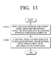
- FIG. 13 is a flowchart illustrating a method for charging an external device in a displaying apparatus which charges the external device connected thereto through a USB connector, according to an exemplary embodiment
- FIG. 14 is a flowchart illustrating a method for charging an external device in a displaying apparatus which charges the external device connected thereto through a new interface, according to another exemplary embodiment.
- FIG. 15 is a flowchart illustrating a method for charging an external device connected to a displaying apparatus applying different types of interfaces, according to an exemplary embodiment.
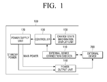
- FIG. 1 is a schematic block diagram of a displaying apparatus 100 which charges an external device connected thereto through a USB connector, according to an exemplary embodiment.
- the displaying apparatus 100 is connected to an external device 200 to charge the external device 200.
- the displaying apparatus also includes an external device connection checker 110, a power supply unit 120, a controller 130, a power output unit 140, and a charge state information display unit 150.
- the external device connection checker 110 checks whether the external device 200 connected to the displaying apparatus 100 through a data line of a USB connector is a chargeable device.
- the external device connection checker 110 may check whether the external device 200 is a chargeable device, using standby power connected to the data line of the USB.
- standby power is used to sense a key input performed by a remote controller.
- the standby power of the displaying apparatus 100 is used to sense the external device 200 if the displaying apparatus 100 is in the standby mode.
- the external device connection checker 110 may check whether the external device 200 is a chargeable device, through paths formed by two data lines connected to the standby power of the displaying apparatus 100.
- a resistor may be switched and connected to one of the two data lines on the paths in the displaying apparatus 100 to check whether the external device 200 is a chargeable device.
- an end resistor of the external device 200 may be formed between the two data lines on a path in the external device 200.
- the end resistor may be a resistor which is formed in the external device 200 or a resistor which is connected to the external device 200 by a switch.
- a displaying apparatus when a displaying apparatus operates normally, an external device, such as a mobile device, are operated normally and charged, and in the related art, when the displaying apparatus is turned off, the external device cannot be charged.
- the displaying apparatus when the displaying apparatus is in a standby mode, only a minimum part of the displaying apparatus, which can perform a charging function, is turned on to sense whether the external device has been connected to the displaying apparatus and to check whether the external device is a chargeable device. As a result, the displaying apparatus may charge the external device.
- the power supply unit 120 outputs the standby power or main power under control of the controller 130 which will be described later.
- the controller 130 controls the power supply unit 120 to output the standby power or the main power, depending on whether the displaying apparatus 100 is in the standby mode.
- the power output unit 140 outputs the standby power or the main power, which is output from the power supply unit 120, to the external device 200.
- the power output unit 140 supplies the main power output from the power supply unit 120 to the external device 200 through a VBUS line of the USB connector to charge the external device 200.
- the displaying apparatus 100 enables the main power to supply the main power to the external device 200 through the power output unit 140, thereby starting charging the external device 200.
- the main power supplied from the power supply unit 140 is cut, and charging of the external device 200 is ended.
- the external device connection checker 110 recognizes that the external device 200 has been disconnected from the displaying apparatus 100 and turns off the power supply unit 120 of the displaying apparatus 100 connected to the VBUS line.
- the external device connection checker 110 recognizes that the external device 200 has been disconnected from the displaying apparatus 100 and turns off the power supply unit 120 of the displaying apparatus 100 connected to the VBUS line.
- the charge state information display unit 150 displays a charge state of the external device 200.
- the charge state information display unit 150 may be a display unit of the displaying apparatus 100 or a light-emitting diode (LED) which is formed in the displaying apparatus 100.
- LED light-emitting diode
- a method for displaying information when charging an external device may be classified into a method for actually displaying information on a display unit of a displaying apparatus, such as a TV screen, and a method for indirectly providing information to a user using an LED formed in the displaying apparatus.
- the charge state of the external device may be displayed according to a color of the LED. For example, if the external device is being charged, the LED emits a red color to display corresponding information. If the external device is completely charged, the LED emits a green color to display the corresponding information. If the external device is disconnected from the displaying apparatus, the LED is turned off to display the corresponding information.
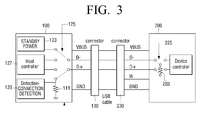
- FIGS. 2 and 3 are views illustrating methods performed by the displaying apparatus 100 of FIG. 1 to recognize the external device 200, according to exemplary embodiments.
- the displaying apparatus 100 is connected to the external device 200 by a USB connector 130 on the displaying apparatus 100 side and a USB connector 230 on the external device 200 side.
- a USB cable is connected between the USB connector 130 and the USB connector 230.
- the displaying apparatus 100 includes standby power 123, a switch 125, a host controller 127, a detection-connection detection 129, and a pull-down resistor 111.
- the external device 200 includes a device controller 210, a switch 225, and an end resistor 201.
- the USB connector 130 includes a VBUS terminal, a data line D- terminal, a data line D+ terminal, and a ground (GND) terminal.
- the USB connector 230 includes a VBUS terminal, a data line D- terminal, a data line D+ terminal, an IN terminal, and a ground (GND) terminal.
- the switch 125 operates to connect standby power 123 to the data line D- of the USB connector 130 and the pull-down resistor 111 to the data line D+ of the USB connector 130 in order to check whether the external device 200 is a chargeable device.
- a path is formed on a circuit.
- the path may be formed using an end resistor 201 of a USB line as shown in FIG. 2 .
- the external device 200 may include the device controller 110, the switch 225 and an end resistor 203.
- the path may be formed using the end resistor 203 which is connected to the USB line using the switch 225 in the external device 200.
- the switch 225 is connected to the end resistor 203 if USB data communication is not used. In the other cases, the switch operates on an original path.
- the displaying apparatus 100 operates a circuit which supplies a current to charge the external device 200 in the standby mode.
- the external device 200 If the external device 200 is completely charged, the external device 200 blocks a resistor path using the switch 225 as shown in FIG. 3 . In this case, the displaying apparatus 100 senses that it is unnecessary to charge the external device 200 and switches over from an external device charge mode to the standby mode.
- an external device connection checker 110 of a displaying apparatus 100 determines in a standby mode that the external device 200 has been connected to the displaying apparatus 100 and is a chargeable device, the external device connection checker 110 instructs a controller 130 to supply main power for charging the external device 200.
- a power supply unit 120 of the displaying apparatus 100 supplies a minimum amount of current for charging to a power output unit 140. The current is transmitted to the external device 200 through a VBUS terminal of a USB connector 230 to start charging the external device.
- the external device connection checker 110 of the displaying apparatus 100 senses that the external device 200 has been disconnected from the displaying apparatus 100.
- the external device connection checker 110 also transmits an OFF command to the controller 130 of the displaying apparatus 100 to turn OFF the power supply unit 120, and the displaying apparatus 100 switches over to the standby mode.
- a charge state of the external device 200 is displayed using an LED.
- the LED is turned off in a standby mode, emits a red color when charging the external device, and emits a green color when the external device 200 is completely charged, thereby helping a user recognize the charge state of the external device 200.
- the displaying apparatus 100 senses a current/voltage to determine whether the external device 200 has been completely charged.
- such a circuit costs much and thus is easily realized by blocking a path of an external device 200 using a switch 225 if the external device 200 is completely charged.
- an external device connection checker 110 determines that the external device 200 has been disconnected from the displaying apparatus 100. Therefore, the external device connection checker 110 transmits an OFF command to a controller so that a power supply unit 120 cuts main power for charging the external device 200.
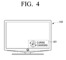
- FIG. 4 is a view illustrating a charge state of an external device in a displaying apparatus, according to an exemplary embodiment.
- Examples of a method for displaying a charge state of the external device 200 when charging the external device 200 may include a method for actually providing information to a display unit of the displaying apparatus 100 as on a TV screen as described above and a method for indirectly providing information to a user using an LED. For example, as shown in FIG. 4 , a part 401 of a whole screen of a display unit is driven to provide information.
- FIG. 5 is a schematic block diagram of a displaying apparatus 400 which charges an external device connected thereto through a new interface, according to another exemplary embodiment.
- the new interface used in the displaying apparatus according to the current exemplary embodiment refers to an interface through which the displaying apparatus and the external device communicate with each other using five lines.
- the new interface will be referred to as a NIF.
- the displaying apparatus 400 charges at least one or more external devices 300 which are connected to the displaying apparatus 400 through five lines.
- the displaying apparatus 400 includes a wakeup signal receiver 410 and a power supply unit 430.
- the wakeup signal receiver 410 receives a wakeup signal to recognize the at least one or more external devices 300 through at least one of first and second lines of the five lines.
- the wakeup signal may include at least one of a start signal to signal a start of the wakeup signal, an external device selection signal to select one of external devices, and a wakeup mode signal to designate wakeup modes of the external devices.
- the start signal may be a signal which falls from a high level to a low level and then is maintained on the low level for a preset time or a signal which rises from the low level to the high level and then is maintained on the high level for a preset time.
- the wakeup mode signal may include a wakeup mode for charging an external device and at least one or more other operation modes.
- the power supply unit 430 supplies power to the external devices 300 through at least one of third and fourth lines of the five lines, according to the received wakeup signal.
- the fifth line of the five lines is a line between the wakeup signal receiver 410 and the power supply unit 430.
- FIGS. 6 and 7 are views respectively illustrating methods performed by a displaying apparatus, which is connected to an external device through a NIF, to charge the external device, according to exemplary embodiments.
- a displaying apparatus 400 is connected to an external device 300.
- the displaying apparatus 400 includes a wakeup signal receiver 410, a power supply unit (SMPS) 430, a receiver Rx, a transmitter Tx, and a NIF 440.
- the wakeup signal receiver 410 further includes a microcomputer (Micom) 415 and a switch SW3.
- the wakeup signal receiver 410 receives a wakeup signal through one of the five lines of the NIF 440 to recognize an external device 300.
- the external device 300 may include a wakeup signal receiver 310, a power supply unit (SMPS) 330, a receiver Rx, a transmitter Tx, and a NIF 340.
- SMPS power supply unit
- the wakeup signal receiver 310 may also include a microcomputer (Micom) 315 and a switch SW1.
- the transmitter Tx of the displaying apparatus 400 communicates with the receiver Rx of the external device 300, and the transmitter Tx of the external device 300 communicates with the receiver Rx of the displaying apparatus 400.
- the displaying apparatus 400 includes the power supply unit (SMPS) 430 to supply power to the external device 300 through two of the five lines of the NIF 440.
- SMPS power supply unit
- an initial wakeup process is performed using one of the five lines.
- Power is supplied to the external device 300 through a different line from the line through which the wakeup process is performed, in order to operate and charge the external device 300.
- the wakeup process is performed using one line in FIG. 6 but may be performed using two lines.
- a charging process is performed using two lines in FIG. 7 but may be performed using one line.
- FIGS. 8A through 8D are views illustrating structures and functions of a wakeup signal.
- FIG. 8A is a view illustrating a structure of a wakeup signal if there is one external device.
- the wakeup signal includes a start signal to signal a start of the wakeup signal and a wakeup mode signal to designate a wakeup mode of the external device.
- an ACK signal is transmitted to the external device to acknowledge the receipt of the wakeup signal.
- the start signal may be a signal which falls from a high level to a low level and then is maintained on the low level for a preset time.
- the present inventive concept is not limited thereto, and the start signal may a signal which rises from the low level to the high level and then is maintained on the high level for a preset time.
- FIG. 8B is a view illustrating a structure of a wakeup signal if there are a plurality of external devices.
- the wakeup signal includes a start signal to signal a start of the wakeup signal, a wakeup port signal to select one of the plurality of external devices, and a wakeup mode to designate a wakeup mode of the selected external device.
- an ACK signal is transmitted to the external device to acknowledge the receipt of the wakeup signal.
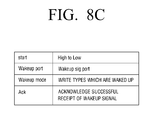
- FIG. 8C is a view illustrating functions of signals included in a wakeup signal.
- a start signal is a signal which falls from a high level to a low level.
- a wakeup port signal is a signal to designate a port corresponding to one of a plurality of external devices.
- a wakeup mode signal is a signal to designate a wakeup mode of the external device.
- An ACK signal is a signal to acknowledge the successful receipt of the wakeup signal.
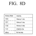
- FIG. 8D is a view illustrating types of wakeup mode signal shown in FIG. 8C .
- Various wakeup modes of an external device are designated according to the types of the wakeup mode signal.
- a specific signal is designated specifically to indicate a function of charging the external device.
- the other wakeup mode signals designate functions other than the charging function.
- FIGS. 9A and 9B are views illustrating a structure of an interface applied between a displaying apparatus and an external device, according to exemplary embodiments.
- FIG. 9A is a view illustrating a structure of a USB type interface.
- a first terminal (Pin 1) supplies power
- second and third terminals (Pin 2 and Pin 3, respectively) perform data communication
- a fourth terminal (Pin 4) is used to recognize a host or an external device
- a fifth terminal (Pin 5) is a ground.
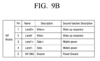
- FIG. 9B is a view illustrating a structure of an NIF type interface.
- First and second terminals (Pin 1 and Pin 2, respectively) are used to perform video communication and to perform a wakeup process in the present exemplary embodiment.
- Third and fourth terminals (Pin 3 and Pin 4, respectively) are used to perform data communication and to perform a process of charging an external device in the present exemplary embodiment.
- a fifth terminal (Pin 5) is a ground. It is noted that the pin assignments are exemplary.
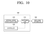
- FIG. 10 is a schematic block diagram of an external device 600 which is connected to a displaying apparatus 500 applying different types of interfaces to be charged, according to an exemplary embodiment.
- the external device 600 is connected to the displaying apparatus 500 applying the different types of interfaces to be charged.
- the external device 600 includes a switching unit 610, an external device power supply unit 620, and a controller 630.
- the switching unit 610 is connected to the displaying apparatus 500 applying the different types of interfaces and is switched to select an interface type corresponding to an interface type applied to the displaying apparatus 500.
- the controller 630 provides a control signal to the switching unit 610 to select the interface type.
- the external device power supply unit 620 is supplied with power using a different method according to the interface type selected by the operation of the switching unit 610.
- the external device power supply unit 620 may be supplied with power through a VBUS line of a plurality of lines according to the first interface.
- the external device power supply unit 620 may be supplied with power through a data line of a plurality of lines according to the second interface.
- the external device 600 may detect to which type of interface it is connected according to which pin of the connector power is supplied.
- the controller 630 detects the type of interface and outputs a control signal to the switching unit 610 to select the interface type corresponding to the interface type applied to the displaying apparatus 500, according to the interface type of the displaying apparatus 500.
- an external device which is connected to a displaying apparatus applying different types of interfaces to be charged, may be connected to a displaying apparatus supporting both of USB and NIF type interfaces to be charged and perform data communication.
- a switching unit of the external device operates in an NIF way by default and is connected to a displaying apparatus applying a USB type interface
- the switching unit senses the external device and switches from an NIF type interface to the USB type interface.
- the switching unit supplies power through a VBUS line.
- a back end of the switching unit supplies power using data lines in the case of an NIF type interface.
- FIGS. 11 and 12 are views respectively illustrating methods for charging the external device 600 of FIG. 10 connected to the displaying apparatus 500 of FIG. 10 applying the different types of interfaces, according to exemplary embodiments.
- the external device 600 shown in FIGS. 11 and 12 is described as a mobile device, but the present inventive concept is not limited thereto.
- the external device 600 may be various types of portable devices such as a Motion Pictures Experts Group (MPEG) Audio Layer-3 (MP3) player, a digital versatile disc (DVD) player, etc.
- MPEG Motion Pictures Experts Group
- MP3 Motion Pictures Experts Group
- DVD digital versatile disc
- FIG. 11 is a view illustrating a method for charging the external device 600 if an interface applied to the displaying apparatus 500 of FIG. 10 is a USB type interface.
- the displaying apparatus 500 includes a power supply unit (SMPS) 510, a USB host 520, and a connector 525, and the SMPS 510 is connected to pin 1 of the connector 525.
- the external device 600 includes mobile power 620, a switch 210, a connector 625, a NIF transceiver 630, and a media processor 640. If the displaying apparatus 500 applies the USB type interface, the NIF transceiver 630 outputs a control signal to the switching unit 610 to select an interface type corresponding to the USB type interface of the displaying apparatus 500. Also, the mobile power 620 is supplied with power through a VBUS line.
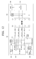
- FIG. 12 is a view illustrating a method for charging the external device 600 if an interface applied to the displaying apparatus 500 is an NIF type interface.
- the displaying apparatus includes a power supply unit (SMPS) 530, a NIF transceiver 540, and a connector 545, and the SMPS 530 is connected to pin 3 and pin 4 of the connector 545.
- the NIF transceiver 630 outputs a control signal to the switching unit 610 to select an interface type corresponding to the NIF type interface of the displaying apparatus 500.
- the mobile power 620 is supplied with power through two data lines of a plurality of lines according to the NIF interface.
- FIG. 13 is a flowchart illustrating a method for charging an external device in a displaying apparatus which charges the external device connected thereto through a USB connector to charge the external device, according to an exemplary embodiment.
- the displaying apparatus is in a standby mode, and checks whether the external device is a chargeable device and has been connected thereto through a USB connector (S1310).
- the displaying apparatus may use standby power to check whether the external device is the chargeable device, according to an intensity of a current flowing into a USB data line.
- operation S1310 is to check whether the external device is the chargeable device and has been connected to the displaying apparatus, through a path formed by two data lines connected to the standby power of the displaying apparatus.
- a resistor may be switched and connected to one of two data lines on a path of the displaying apparatus to check whether the external device is the chargeable device.
- An end resistor of the external device may be formed between two data lines on a path of the external device.
- the end resistor may be a resistor which is formed in the external device or a resistor which is connected to a switch.
- the displaying apparatus charges the external device through a VBUS line of a USB connector in the standby mode (S1330).
- operation S1330 is to charge the external device using main power of the displaying apparatus connected to the VBUS line.
- the method may further include displaying a charge state of the external device.
- the charge state of the external device may be displayed through an LED formed in the displaying apparatus or through a display unit of the displaying apparatus.
- the method may further include recognizing that the external device has been disconnected from the displaying apparatus and turning off a power supply unit of the displaying apparatus connected to the VBUS line.
- the method may further include recognizing that the external device has been disconnected from the displaying apparatus and turning off the power supply unit of the displaying apparatus connected to the VBUS line.
- FIG. 14 is a flowchart illustrating a method for charging an external device in a displaying apparatus which charges the external device connected thereto through a NIF, according to another exemplary embodiment.
- the NIF is connected to a displaying apparatus through five lines.
- a wakeup signal is received through at least one of first and second lines of the five lines to recognize at least one external device (S1410).
- the wakeup signal may be received through one or two of five lines of NIF type.
- the wakeup signal may include at least one of a start signal to signal a start of the wakeup signal, a wakeup port signal to select one of at least one or more external devices, and a wakeup mode signal to designate wakeup modes of the external devices.
- the start signal may be a signal which falls from a high level to a low level and then is maintained on the low level for a preset time or a signal which rises from a low level to a high level and then is maintained on the high level for a preset time.
- the wakeup mode signal may include a wakeup mode for charging an external mode and at least one or more other wakeup modes.
- the method may further include transmitting an ACK signal, which is to acknowledge the receipt of the wakeup signal, to the external device after completely receiving the wakeup signal.
- the external device is charged through at least one of third and fourth lines of the five lines according to the received wakeup signal (S1430).
- FIG. 15 is a flowchart illustrating a method for charging an external device connected to a displaying apparatus applying different types of interfaces, according to an exemplary embodiment.
- the external device to which an NIF type interface is applied by default is connected to the displaying apparatus (S1501).
- a wakeup process is performed to wake up the displaying apparatus (S1509).
- Data communication is performed through an NIF type interface (S1511). Audio/Video (AN) and data are transmitted (S1513).
- NIF type interface S1511. Audio/Video (AN) and data are transmitted (S1513).
- a charge command is received (S1515).
- a determination is made as to whether the displaying apparatus is in a standby mode (S1517).
- the displaying apparatus is in the standby mode (S1517-Y)
- the displaying apparatus is turned on without turning on a screen (S1521).
- Charging power is supplied (S1523). If the external device is completely charged, the displaying apparatus switches over to the standby mode (S1525).
Landscapes
- Engineering & Computer Science (AREA)
- Theoretical Computer Science (AREA)
- Physics & Mathematics (AREA)
- General Physics & Mathematics (AREA)
- General Engineering & Computer Science (AREA)
- Power Engineering (AREA)
- Computer Hardware Design (AREA)
- Charge And Discharge Circuits For Batteries Or The Like (AREA)
- Power Sources (AREA)
- Secondary Cells (AREA)
- Television Receiver Circuits (AREA)
Abstract
Description
- This application claims priority from Korean Patent Application No.
10-2010-0122277, filed on December 2, 2010 - Methods and apparatuses consistent with exemplary embodiments relate to charging an external device and, more particularly, to charging an external device according to a mode of a displaying apparatus.
- An external device, such as a mobile device or the like, may be connected to a displaying apparatus and has been generally charged using an additional charger. However, in most cases, a mobile connector is connected to a displaying apparatus, such as a television (TV), so that the displaying apparatus performs both its own operations and a charging process for the external device.
- If an external device is connected to a displaying apparatus, and the displaying apparatus is in a normal state such as an ON state, this is not a particular problem. However, if the displaying apparatus is turned OFF to be in a standby mode and the external device is connected, the displaying apparatus is unnecessarily turned ON.
- In particular, if the displaying apparatus is in the standby mode, power is not supplied to a universal serial bus (USB) connector, and thus the displaying apparatus is turned ON to supply the power to the USB connector. In this case, power is unnecessarily consumed only for charging.
- One or more exemplary embodiments may overcome the above disadvantages and other disadvantages not described above. However, it is understood that one or more exemplary embodiment are not required to overcome the disadvantages described above, and may not overcome any of the disadvantages described above.
- One or more exemplary embodiments provide a method for charging an external device by which unnecessary power consumption can be alleviated, and a displaying apparatus using thereof.
- According to an aspect of an exemplary embodiment, there is provided a method for charging an external device using a displaying apparatus, the method comprising determining whether the external device is a chargeable device and has been connected to the displaying apparatus through a Universal Serial Bus (USB) connector, when the displaying apparatus is in a standby mode; and if it is determined that the external device is a chargeable device and has been connected to the displaying apparatus, charging the external device through the USB connector in the standby mode.
- Standby power of the displaying apparatus may be used to check whether the external device is a chargeable device, according to an intensity of a current flowing into a data line of the USB connector.
- The external device may be charged using main power of the displaying apparatus connected to a VBUS line of the USB connector.
- Whether the external device is the chargeable device and has been connected to the displaying apparatus may be checked through a path formed by two data lines connected to the standby power of the displaying apparatus.
- A resistor may be switched and connected to one of the two data lines on the path to check whether the external device is a chargeable device.
- An end resistor of the external device, which is formed between the two data lines, may be included on the path.
- The end resistor may be a resistor which is formed in the external device, or a resistor which is connected to the external device through a switch.
- The method may further include displaying a charge state of the external device.
- The charge state of the external device may be displayed through a light-emitting diode (LED) provided in the displaying apparatus, or through a display unit of the displaying apparatus.
- If the external device is disconnected from the displaying apparatus, the method may further include recognizing that the external device has been disconnected from the displaying apparatus and turning off a power supply unit of the displaying apparatus that is connected to the VBUS line.
- If the external device is completely charged, the method may further include recognizing that the external device has been disconnected from the displaying apparatus and turning off a power supply unit of the displaying apparatus that is connected to the VBUS line.
- According to an aspect of another exemplary embodiment, there is provided a displaying apparatus for charging an external device which is connected to the display apparatus using a Universal Serial Bus (USB) connector, the displaying apparatus comprising an external device connection checker which determines whether the external device connected to the displaying apparatus using the USB connector is a chargeable device; a power supply unit which outputs standby power or main power; a controller which controls the power supply unit to output the standby power or the main power depending on whether the displaying apparatus is in a standby mode; and a power output unit which outputs the standby power or the main power, which is output from the power supply unit, to the external device based on the determination of the external device connection checker.
- The external device connection checker may check whether the external device is a chargeable device, using the standby power connected to a data line of the USB connector.
- The power output unit may supply the main power, which is output from the power supply unit, to the external device through a VBUS line of the USB connector to charge the external device.
- The displaying apparatus may further include a charge state information display unit which displays a charge state of the external device.
- The charge state information display unit may be a display unit of the displaying apparatus, or an LED which is provided in the displaying apparatus.
- According to an aspect of another exemplary embodiment, there is provided a method for charging one or more external devices which are connected to a displaying apparatus through five lines, the method comprising receiving a wakeup signal through at least one of first and second lines of the five lines to recognize the one or more external devices; and charging the one or more external devices through at least one of third and fourth lines of the five lines according to the received wakeup signal.
- The wakeup signal may include at least one of a start signal to signal a start of the wakeup signal, a wakeup port signal to select one of the one or more external devices, and a wakeup mode signal to designate a wakeup mode of the external device.
- The start signal may be a signal which falls from a high level to a low level and then is maintained on the low level for a preset time, or a signal which rises from the low level to the high level and then is maintained on the high level for a preset time.
- The wakeup mode signal may include a wakeup operation mode for charging the external device and at least one other wakeup mode.
- In response to the wakeup signal, the method may further include transmitting an acknowledgement (ACK) signal, which acknowledges the receipt of the wakeup signal, to the external device.
- According to an aspect of another exemplary embodiment, there is provided a displaying apparatus for charging one or more external devices which are connected to the displaying apparatus through five lines, the displaying apparatus comprising a wakeup signal receiver which receives a wakeup signal through at least one of first and second lines of the five lines to recognize the one or more external devices; and a power supply unit which supplies power to the external devices through at least one of third and fourth lines of the five lines according to the received wakeup signal.
- The wakeup signal may include at least one of a start signal to signal a start of the wakeup signal, a wakeup port signal to select one of the one or more external devices, and a wakeup mode signal to designate wakeup modes of the external devices.
- The start signal may be a signal which falls from a high level to a low level and then is maintained on the low level for a preset time or a signal which rises from the low level to the high level and then is maintained on the high level for a preset time.
- The wakeup mode signal may include a wakeup operation mode for charging the external device and at least one other wakeup mode.
- The above and/or other aspects will be more apparent by describing in detail exemplary embodiments, with reference to the accompanying drawings, in which:
-
FIG. 1 is a schematic block diagram of a displaying apparatus which charges an external device connected thereto through a USB connector, according to an exemplary embodiment; -
FIGS. 2 and3 are views respectively illustrating methods performed by the displaying apparatus ofFIG. 1 to recognize an external device , according to exemplary embodiments; -
FIG. 4 is a view illustrating a charge state of an external device in a displaying apparatus, according to an exemplary embodiment; -
FIG. 5 is a schematic block diagram of a displaying apparatus which charges an external device connected thereto through a new interface, according to another exemplary embodiment; -
FIGS. 6 and7 are views respectively illustrating methods performed by a displaying apparatus ofFIG. 5 , which is connected to an external device through a new interface, to charge the external device, according to exemplary embodiments; -
FIGS. 8A through 8D are views illustrating structures and functions of a wakeup signal; -
FIGS. 9A and9B are views illustrating structures of interfaces applied between a displaying apparatus and an external device, according to exemplary embodiments; -
FIG. 10 is a schematic block diagram of an external device which is connected to a displaying apparatus applying different types of interfaces to perform a charge function, according to an exemplary embodiment; -
FIGS. 11 and12 are views respectively illustrating methods for charging the external device ofFIG. 10 connected to a displaying apparatus applying different types of interfaces, according to exemplary embodiments; -
FIG. 13 is a flowchart illustrating a method for charging an external device in a displaying apparatus which charges the external device connected thereto through a USB connector, according to an exemplary embodiment; -
FIG. 14 is a flowchart illustrating a method for charging an external device in a displaying apparatus which charges the external device connected thereto through a new interface, according to another exemplary embodiment; and -
FIG. 15 is a flowchart illustrating a method for charging an external device connected to a displaying apparatus applying different types of interfaces, according to an exemplary embodiment. - Hereinafter, exemplary embodiments will be described in greater detail with reference to the accompanying drawings.
- In the following description, same reference numerals are used for the same elements when they are depicted in different drawings. The matters defined in the description, such as detailed construction and elements, are provided to assist in a comprehensive understanding of the exemplary embodiments. Thus, it is apparent that the exemplary embodiments can be carried out without those specifically defined matters. Also, functions or elements known in the related art are not described in detail since they would obscure the exemplary embodiments with unnecessary detail.
-
FIG. 1 is a schematic block diagram of a displayingapparatus 100 which charges an external device connected thereto through a USB connector, according to an exemplary embodiment. - Referring to
FIG. 1 , the displayingapparatus 100 is connected to anexternal device 200 to charge theexternal device 200. The displaying apparatus also includes an externaldevice connection checker 110, apower supply unit 120, acontroller 130, apower output unit 140, and a charge stateinformation display unit 150. - The external
device connection checker 110 checks whether theexternal device 200 connected to the displayingapparatus 100 through a data line of a USB connector is a chargeable device. - The external
device connection checker 110 may check whether theexternal device 200 is a chargeable device, using standby power connected to the data line of the USB. - In other words, if a related art displaying apparatus is in a standby mode, standby power is used to sense a key input performed by a remote controller. However, the standby power of the displaying
apparatus 100 according to the present exemplary embodiment is used to sense theexternal device 200 if the displayingapparatus 100 is in the standby mode. - According to an exemplary embodiment, the external
device connection checker 110 may check whether theexternal device 200 is a chargeable device, through paths formed by two data lines connected to the standby power of the displayingapparatus 100. - Here, a resistor may be switched and connected to one of the two data lines on the paths in the displaying
apparatus 100 to check whether theexternal device 200 is a chargeable device. - Also, an end resistor of the
external device 200 may be formed between the two data lines on a path in theexternal device 200. Here, the end resistor may be a resistor which is formed in theexternal device 200 or a resistor which is connected to theexternal device 200 by a switch. - In other words, when a displaying apparatus operates normally, an external device, such as a mobile device, are operated normally and charged, and in the related art, when the displaying apparatus is turned off, the external device cannot be charged. However, in the exemplary embodiment, when the displaying apparatus is in a standby mode, only a minimum part of the displaying apparatus, which can perform a charging function, is turned on to sense whether the external device has been connected to the displaying apparatus and to check whether the external device is a chargeable device. As a result, the displaying apparatus may charge the external device.
- The
power supply unit 120 outputs the standby power or main power under control of thecontroller 130 which will be described later. - The
controller 130 controls thepower supply unit 120 to output the standby power or the main power, depending on whether the displayingapparatus 100 is in the standby mode. - The
power output unit 140 outputs the standby power or the main power, which is output from thepower supply unit 120, to theexternal device 200. - Here, the
power output unit 140 supplies the main power output from thepower supply unit 120 to theexternal device 200 through a VBUS line of the USB connector to charge theexternal device 200. - In other words, if it is determined that the
external device 200 is a chargeable device, the displayingapparatus 100 enables the main power to supply the main power to theexternal device 200 through thepower output unit 140, thereby starting charging theexternal device 200. - Here, if the
external device 200 is completely charged or disconnected from the displayingapparatus 100, the main power supplied from thepower supply unit 140 is cut, and charging of theexternal device 200 is ended. - In more detail, if the
external device 200 is disconnected from the displayingapparatus 100, the externaldevice connection checker 110 recognizes that theexternal device 200 has been disconnected from the displayingapparatus 100 and turns off thepower supply unit 120 of the displayingapparatus 100 connected to the VBUS line. - If the
external device 100 is completely charged, the externaldevice connection checker 110 recognizes that theexternal device 200 has been disconnected from the displayingapparatus 100 and turns off thepower supply unit 120 of the displayingapparatus 100 connected to the VBUS line. - The charge state
information display unit 150 displays a charge state of theexternal device 200. - Here, the charge state
information display unit 150 may be a display unit of the displayingapparatus 100 or a light-emitting diode (LED) which is formed in the displayingapparatus 100. - In other words, a method for displaying information when charging an external device may be classified into a method for actually displaying information on a display unit of a displaying apparatus, such as a TV screen, and a method for indirectly providing information to a user using an LED formed in the displaying apparatus.
- If a charge state of an external device is displayed using an LED, the charge state of the external device may be displayed according to a color of the LED. For example, if the external device is being charged, the LED emits a red color to display corresponding information. If the external device is completely charged, the LED emits a green color to display the corresponding information. If the external device is disconnected from the displaying apparatus, the LED is turned off to display the corresponding information.
-
FIGS. 2 and3 are views illustrating methods performed by the displayingapparatus 100 ofFIG. 1 to recognize theexternal device 200, according to exemplary embodiments. - As shown in
FIG. 2 , the displayingapparatus 100 is connected to theexternal device 200 by aUSB connector 130 on the displayingapparatus 100 side and aUSB connector 230 on theexternal device 200 side. A USB cable is connected between theUSB connector 130 and theUSB connector 230. The displayingapparatus 100 includesstandby power 123, aswitch 125, ahost controller 127, a detection-connection detection 129, and a pull-down resistor 111. Theexternal device 200 includes a device controller 210, aswitch 225, and anend resistor 201. TheUSB connector 130 includes a VBUS terminal, a data line D- terminal, a data line D+ terminal, and a ground (GND) terminal. TheUSB connector 230 includes a VBUS terminal, a data line D- terminal, a data line D+ terminal, an IN terminal, and a ground (GND) terminal. - If the displaying
apparatus 100 is in a standby mode, theswitch 125 operates to connectstandby power 123 to the data line D- of theUSB connector 130 and the pull-down resistor 111 to the data line D+ of theUSB connector 130 in order to check whether theexternal device 200 is a chargeable device. - Here, a path is formed on a circuit. The path may be formed using an
end resistor 201 of a USB line as shown inFIG. 2 . Alternatively, as shown inFIG. 3 , theexternal device 200 may include thedevice controller 110, theswitch 225 and anend resistor 203. In this case, the path may be formed using theend resistor 203 which is connected to the USB line using theswitch 225 in theexternal device 200. - If the
end resistor 203 connected to the USB line using theswitch 225 as shown inFIG. 3 is used, theswitch 225 is connected to theend resistor 203 if USB data communication is not used. In the other cases, the switch operates on an original path. - As described above with reference to
FIGS. 2 and3 , if it is determined that theexternal device 200 has been connected to the displayingapparatus 100 and is a chargeable device, the displayingapparatus 100 operates a circuit which supplies a current to charge theexternal device 200 in the standby mode. - If the
external device 200 is completely charged, theexternal device 200 blocks a resistor path using theswitch 225 as shown inFIG. 3 . In this case, the displayingapparatus 100 senses that it is unnecessary to charge theexternal device 200 and switches over from an external device charge mode to the standby mode. - Here, a charging process will now be described in more detail. If an external
device connection checker 110 of a displayingapparatus 100, to which anexternal device 200 is connected, determines in a standby mode that theexternal device 200 has been connected to the displayingapparatus 100 and is a chargeable device, the externaldevice connection checker 110 instructs acontroller 130 to supply main power for charging theexternal device 200. In this case, apower supply unit 120 of the displayingapparatus 100 supplies a minimum amount of current for charging to apower output unit 140. The current is transmitted to theexternal device 200 through a VBUS terminal of aUSB connector 230 to start charging the external device. If theexternal device 200 is disconnected from the displayingapparatus 100, the externaldevice connection checker 110 of the displayingapparatus 100 senses that theexternal device 200 has been disconnected from the displayingapparatus 100. The externaldevice connection checker 110 also transmits an OFF command to thecontroller 130 of the displayingapparatus 100 to turn OFF thepower supply unit 120, and the displayingapparatus 100 switches over to the standby mode. - When the
external device 200 is charged, a charge state of theexternal device 200 is displayed using an LED. For example, the LED is turned off in a standby mode, emits a red color when charging the external device, and emits a green color when theexternal device 200 is completely charged, thereby helping a user recognize the charge state of theexternal device 200. In order to recognize that theexternal device 200 has been completely charged, the displayingapparatus 100 senses a current/voltage to determine whether theexternal device 200 has been completely charged. However, in general, such a circuit costs much and thus is easily realized by blocking a path of anexternal device 200 using aswitch 225 if theexternal device 200 is completely charged. In other words, if the path of theexternal device 200 is blocked, an externaldevice connection checker 110 determines that theexternal device 200 has been disconnected from the displayingapparatus 100. Therefore, the externaldevice connection checker 110 transmits an OFF command to a controller so that apower supply unit 120 cuts main power for charging theexternal device 200. -
FIG. 4 is a view illustrating a charge state of an external device in a displaying apparatus, according to an exemplary embodiment. - Examples of a method for displaying a charge state of the
external device 200 when charging theexternal device 200 may include a method for actually providing information to a display unit of the displayingapparatus 100 as on a TV screen as described above and a method for indirectly providing information to a user using an LED. For example, as shown inFIG. 4 , apart 401 of a whole screen of a display unit is driven to provide information. -
FIG. 5 is a schematic block diagram of a displayingapparatus 400 which charges an external device connected thereto through a new interface, according to another exemplary embodiment. Here, the new interface used in the displaying apparatus according to the current exemplary embodiment refers to an interface through which the displaying apparatus and the external device communicate with each other using five lines. Hereinafter, the new interface will be referred to as a NIF. - As shown in
FIG. 5 , the displayingapparatus 400 charges at least one or moreexternal devices 300 which are connected to the displayingapparatus 400 through five lines. The displayingapparatus 400 includes awakeup signal receiver 410 and apower supply unit 430. - The
wakeup signal receiver 410 receives a wakeup signal to recognize the at least one or moreexternal devices 300 through at least one of first and second lines of the five lines. - According to an exemplary embodiment, the wakeup signal may include at least one of a start signal to signal a start of the wakeup signal, an external device selection signal to select one of external devices, and a wakeup mode signal to designate wakeup modes of the external devices.
- Here, the start signal may be a signal which falls from a high level to a low level and then is maintained on the low level for a preset time or a signal which rises from the low level to the high level and then is maintained on the high level for a preset time.
- The wakeup mode signal may include a wakeup mode for charging an external device and at least one or more other operation modes.
- The
power supply unit 430 supplies power to theexternal devices 300 through at least one of third and fourth lines of the five lines, according to the received wakeup signal. The fifth line of the five lines is a line between thewakeup signal receiver 410 and thepower supply unit 430. -
FIGS. 6 and7 are views respectively illustrating methods performed by a displaying apparatus, which is connected to an external device through a NIF, to charge the external device, according to exemplary embodiments. - As shown in
FIG. 6 , a displayingapparatus 400 is connected to anexternal device 300. The displayingapparatus 400 includes awakeup signal receiver 410, a power supply unit (SMPS) 430, a receiver Rx, a transmitter Tx, and aNIF 440. Thewakeup signal receiver 410 further includes a microcomputer (Micom) 415 and a switch SW3. Thewakeup signal receiver 410 receives a wakeup signal through one of the five lines of theNIF 440 to recognize anexternal device 300. Theexternal device 300 may include awakeup signal receiver 310, a power supply unit (SMPS) 330, a receiver Rx, a transmitter Tx, and aNIF 340. Thewakeup signal receiver 310 may also include a microcomputer (Micom) 315 and a switch SW1. The transmitter Tx of the displayingapparatus 400 communicates with the receiver Rx of theexternal device 300, and the transmitter Tx of theexternal device 300 communicates with the receiver Rx of the displayingapparatus 400. - As shown in
FIG. 7 , the displayingapparatus 400 includes the power supply unit (SMPS) 430 to supply power to theexternal device 300 through two of the five lines of theNIF 440. - In other words, as shown in
FIGS. 6 and7 , an initial wakeup process is performed using one of the five lines. Power is supplied to theexternal device 300 through a different line from the line through which the wakeup process is performed, in order to operate and charge theexternal device 300. The wakeup process is performed using one line inFIG. 6 but may be performed using two lines. A charging process is performed using two lines inFIG. 7 but may be performed using one line. -
FIGS. 8A through 8D are views illustrating structures and functions of a wakeup signal. -
FIG. 8A is a view illustrating a structure of a wakeup signal if there is one external device. The wakeup signal includes a start signal to signal a start of the wakeup signal and a wakeup mode signal to designate a wakeup mode of the external device. As shown inFIG. 8A , after the wakeup signal is completely received, an ACK signal is transmitted to the external device to acknowledge the receipt of the wakeup signal. - The start signal may be a signal which falls from a high level to a low level and then is maintained on the low level for a preset time. However, the present inventive concept is not limited thereto, and the start signal may a signal which rises from the low level to the high level and then is maintained on the high level for a preset time.
-
FIG. 8B is a view illustrating a structure of a wakeup signal if there are a plurality of external devices. The wakeup signal includes a start signal to signal a start of the wakeup signal, a wakeup port signal to select one of the plurality of external devices, and a wakeup mode to designate a wakeup mode of the selected external device. As described with reference toFIG. 8A , inFIG. 8B , after the wakeup signal is completely received, an ACK signal is transmitted to the external device to acknowledge the receipt of the wakeup signal. -
FIG. 8C is a view illustrating functions of signals included in a wakeup signal. As shown inFIG. 8C , a start signal is a signal which falls from a high level to a low level. A wakeup port signal is a signal to designate a port corresponding to one of a plurality of external devices. A wakeup mode signal is a signal to designate a wakeup mode of the external device. An ACK signal is a signal to acknowledge the successful receipt of the wakeup signal. -
FIG. 8D is a view illustrating types of wakeup mode signal shown inFIG. 8C . Various wakeup modes of an external device are designated according to the types of the wakeup mode signal. A specific signal is designated specifically to indicate a function of charging the external device. The other wakeup mode signals designate functions other than the charging function. -
FIGS. 9A and9B are views illustrating a structure of an interface applied between a displaying apparatus and an external device, according to exemplary embodiments. -
FIG. 9A is a view illustrating a structure of a USB type interface. A first terminal (Pin 1) supplies power, second and third terminals (Pin 2 andPin 3, respectively) perform data communication, a fourth terminal (Pin 4) is used to recognize a host or an external device, and a fifth terminal (Pin 5) is a ground. -
FIG. 9B is a view illustrating a structure of an NIF type interface. First and second terminals (Pin 1 andPin 2, respectively) are used to perform video communication and to perform a wakeup process in the present exemplary embodiment. Third and fourth terminals (Pin 3 andPin 4, respectively) are used to perform data communication and to perform a process of charging an external device in the present exemplary embodiment. A fifth terminal (Pin 5) is a ground. It is noted that the pin assignments are exemplary. -
FIG. 10 is a schematic block diagram of anexternal device 600 which is connected to a displayingapparatus 500 applying different types of interfaces to be charged, according to an exemplary embodiment. - Referring to
FIG. 10 , theexternal device 600 is connected to the displayingapparatus 500 applying the different types of interfaces to be charged. Theexternal device 600 includes aswitching unit 610, an external devicepower supply unit 620, and acontroller 630. - The
switching unit 610 is connected to the displayingapparatus 500 applying the different types of interfaces and is switched to select an interface type corresponding to an interface type applied to the displayingapparatus 500. Thecontroller 630 provides a control signal to theswitching unit 610 to select the interface type. - The external device
power supply unit 620 is supplied with power using a different method according to the interface type selected by the operation of theswitching unit 610. - According to an exemplary embodiment, if an interface applied to the displaying
apparatus 500 is a first interface of USB type, the external devicepower supply unit 620 may be supplied with power through a VBUS line of a plurality of lines according to the first interface. - According to another exemplary embodiment, if the interface applied to the displaying
apparatus 500 is a second interface of NIF type, the external devicepower supply unit 620 may be supplied with power through a data line of a plurality of lines according to the second interface. Thus, theexternal device 600 may detect to which type of interface it is connected according to which pin of the connector power is supplied. - The
controller 630 detects the type of interface and outputs a control signal to theswitching unit 610 to select the interface type corresponding to the interface type applied to the displayingapparatus 500, according to the interface type of the displayingapparatus 500. - Accordingly, an external device, which is connected to a displaying apparatus applying different types of interfaces to be charged, according to an exemplary embodiment, may be connected to a displaying apparatus supporting both of USB and NIF type interfaces to be charged and perform data communication. For example, if a switching unit of the external device operates in an NIF way by default and is connected to a displaying apparatus applying a USB type interface, the switching unit senses the external device and switches from an NIF type interface to the USB type interface. In such case, the switching unit supplies power through a VBUS line. A back end of the switching unit supplies power using data lines in the case of an NIF type interface.
-
FIGS. 11 and12 are views respectively illustrating methods for charging theexternal device 600 ofFIG. 10 connected to the displayingapparatus 500 ofFIG. 10 applying the different types of interfaces, according to exemplary embodiments. Theexternal device 600 shown inFIGS. 11 and12 is described as a mobile device, but the present inventive concept is not limited thereto. Theexternal device 600 may be various types of portable devices such as a Motion Pictures Experts Group (MPEG) Audio Layer-3 (MP3) player, a digital versatile disc (DVD) player, etc. -
FIG. 11 is a view illustrating a method for charging theexternal device 600 if an interface applied to the displayingapparatus 500 ofFIG. 10 is a USB type interface. As shown inFIG. 11 , the displayingapparatus 500 includes a power supply unit (SMPS) 510, aUSB host 520, and aconnector 525, and theSMPS 510 is connected to pin 1 of theconnector 525. Theexternal device 600 includesmobile power 620, a switch 210, aconnector 625, aNIF transceiver 630, and amedia processor 640. If the displayingapparatus 500 applies the USB type interface, theNIF transceiver 630 outputs a control signal to theswitching unit 610 to select an interface type corresponding to the USB type interface of the displayingapparatus 500. Also, themobile power 620 is supplied with power through a VBUS line. -
FIG. 12 is a view illustrating a method for charging theexternal device 600 if an interface applied to the displayingapparatus 500 is an NIF type interface. As shown inFIG. 12 , in this case, the displaying apparatus includes a power supply unit (SMPS) 530, aNIF transceiver 540, and aconnector 545, and theSMPS 530 is connected to pin 3 andpin 4 of theconnector 545. If the displayingapparatus 500 applies the NIF type interface, theNIF transceiver 630 outputs a control signal to theswitching unit 610 to select an interface type corresponding to the NIF type interface of the displayingapparatus 500. Themobile power 620 is supplied with power through two data lines of a plurality of lines according to the NIF interface. - Hereinafter, repeated descriptions of a displaying apparatus and an external device will be omitted.
-
FIG. 13 is a flowchart illustrating a method for charging an external device in a displaying apparatus which charges the external device connected thereto through a USB connector to charge the external device, according to an exemplary embodiment. - The displaying apparatus is in a standby mode, and checks whether the external device is a chargeable device and has been connected thereto through a USB connector (S1310).
- According to an exemplary embodiment, the displaying apparatus may use standby power to check whether the external device is the chargeable device, according to an intensity of a current flowing into a USB data line.
- Here, operation S1310 is to check whether the external device is the chargeable device and has been connected to the displaying apparatus, through a path formed by two data lines connected to the standby power of the displaying apparatus.
- Here, a resistor may be switched and connected to one of two data lines on a path of the displaying apparatus to check whether the external device is the chargeable device.
- An end resistor of the external device may be formed between two data lines on a path of the external device.
- Here, the end resistor may be a resistor which is formed in the external device or a resistor which is connected to a switch.
- If it is checked that the external device has been connected to the displaying apparatus, the displaying apparatus charges the external device through a VBUS line of a USB connector in the standby mode (S1330).
- Here, operation S1330 is to charge the external device using main power of the displaying apparatus connected to the VBUS line.
- According to an exemplary embodiment, the method may further include displaying a charge state of the external device.
- Here, the charge state of the external device may be displayed through an LED formed in the displaying apparatus or through a display unit of the displaying apparatus.
- According to an exemplary embodiment, if the external device is disconnected from the displaying apparatus, the method may further include recognizing that the external device has been disconnected from the displaying apparatus and turning off a power supply unit of the displaying apparatus connected to the VBUS line.
- According to another exemplary embodiment, if the external device is completely charged, the method may further include recognizing that the external device has been disconnected from the displaying apparatus and turning off the power supply unit of the displaying apparatus connected to the VBUS line.
-
FIG. 14 is a flowchart illustrating a method for charging an external device in a displaying apparatus which charges the external device connected thereto through a NIF, according to another exemplary embodiment. - Hereinafter, it is assumed that the NIF is connected to a displaying apparatus through five lines.
- A wakeup signal is received through at least one of first and second lines of the five lines to recognize at least one external device (S1410).
- In other words, the wakeup signal may be received through one or two of five lines of NIF type.
- According to an exemplary embodiment, the wakeup signal may include at least one of a start signal to signal a start of the wakeup signal, a wakeup port signal to select one of at least one or more external devices, and a wakeup mode signal to designate wakeup modes of the external devices.
- Here, the start signal may be a signal which falls from a high level to a low level and then is maintained on the low level for a preset time or a signal which rises from a low level to a high level and then is maintained on the high level for a preset time.
- The wakeup mode signal may include a wakeup mode for charging an external mode and at least one or more other wakeup modes.
- According to an exemplary embodiment, the method may further include transmitting an ACK signal, which is to acknowledge the receipt of the wakeup signal, to the external device after completely receiving the wakeup signal.
- The external device is charged through at least one of third and fourth lines of the five lines according to the received wakeup signal (S1430).
-
FIG. 15 is a flowchart illustrating a method for charging an external device connected to a displaying apparatus applying different types of interfaces, according to an exemplary embodiment. - The external device to which an NIF type interface is applied by default is connected to the displaying apparatus (S1501).
- A determination is made as to whether an interface type of the displaying apparatus is a USB type (S1503). If it is determined that the interface type of the displaying apparatus is the USB type (S1503-Y), an interface of the external device switches over to a USB type (S1505).
- Power supply and data communication are performed through the USB type interface (S1507).
- If it is determined that the interface type of the displaying apparatus is not the USB type (S1503-N), a wakeup process is performed to wake up the displaying apparatus (S1509).
- Data communication is performed through an NIF type interface (S1511). Audio/Video (AN) and data are transmitted (S1513).
- After the wakeup process is performed, a charge command is received (S1515). A determination is made as to whether the displaying apparatus is in a standby mode (S1517).
- If it is determined that the displaying apparatus is in a normal mode not in the standby mode (S1517-N), power is supplied to the external device (S1519).
- If it is determined the displaying apparatus is in the standby mode (S1517-Y), the displaying apparatus is turned on without turning on a screen (S1521). Charging power is supplied (S1523). If the external device is completely charged, the displaying apparatus switches over to the standby mode (S1525).
- According to the above-described exemplary embodiments, even when a displaying apparatus is in a standby mode, power is supplied only to an external device to charge the external device, without supplying power to the displaying apparatus.
- The foregoing embodiments and advantages are merely exemplary and are not to be construed as limiting the present inventive concept. The exemplary embodiments can be readily applied to other types of apparatuses. Also, the description of the exemplary embodiments is intended to be illustrative, and not to limit the scope of the claims, and many alternatives, modifications, and variations will be apparent to those skilled in the art.
Claims (15)
- A method for charging an external device using a displaying apparatus, the method comprising:determining whether the external device is a chargeable device and has been connected to the displaying apparatus through a Universal Serial Bus (USB) connector, when the displaying apparatus is in a standby mode; andif it is determined that the external device is a chargeable device and has been connected to the displaying apparatus, charging the external device through the USB connector while the displaying apparatus is in the standby mode.
- The method as claimed in claim 1, wherein the determining whether the external device is a chargeable device comprises supplying standby power of the displaying apparatus to the USB connector and determining an intensity of current flowing through a data line of the USB connector.
- The method as claimed in claim 1 or 2, wherein the charging the external device comprises supplying main power of the displaying apparatus to a VBUS line of the USB connector.
- The method as claimed in claim 1 through 3, wherein whether the external device is a chargeable device and has been connected to the displaying apparatus is determined through a path formed by two data lines connected to standby power of the displaying apparatus.
- The method as claimed in claim 4, wherein the determining whether the external device is a chargeable device comprises switching a resistor to connect the resistor to one of the two data lines on the path.
- The method as claimed in claim 4, wherein the path comprises an end resistor connected between the two data lines.
- The method as claimed in claim 6, wherein the end resistor is a resistor which is provided in the external device, or a resistor which is connected to the external device through a switch.
- The method as claimed in claim 1 through 7, further comprising displaying a charge state of the external device.
- The method as claimed in claim 8, wherein the charge state of the external device is displayed using a light-emitting diode formed in the displaying apparatus or a display unit of the displaying apparatus.
- The method as claimed in claim 1 through 9, further comprising, if the external device is disconnected from the displaying apparatus, recognizing that the external device has been disconnected from the displaying apparatus and turning off a power supply unit of the displaying apparatus connected to the USB connector.
- The method as claimed in claim 1 through 9, further comprising, if the external device is completely charged, recognizing that the external device has been disconnected from the displaying apparatus and turning off a power supply unit of the displaying apparatus connected to the VBUS line.
- A displaying apparatus for charging an external device which is connected to the displaying apparatus through a Universal Serial Bus (USB) connector, the displaying apparatus comprising:an external device connection checker which determines whether the external device connected to the displaying apparatus through the USB connector is a chargeable device;a power supply unit which outputs standby power or main power;a controller which controls the power supply unit to output the standby power or the main power depending on whether the displaying apparatus is in a standby mode; anda power output unit which outputs the standby power or the main power, which is output from the power supply unit, to the external device based on a result of the determination by the external device connection checker.
- The displaying apparatus as claimed in claim 12, wherein the power output unit outputs standby power to the USB connector, and the external device connection checker determines whether the external device is the chargeable device, using the standby power output to the USB connector.
- The displaying apparatus as claimed in claim 12 or 13, wherein the power output unit supplies the main power, which is output from the power supply unit, to the external device through a VBUS line of the USB connector to charge the external device.
- The displaying apparatus as claimed in claim 12 through 14, further comprising a charge state information display unit which displays a charge state of the external device.
Applications Claiming Priority (1)
| Application Number | Priority Date | Filing Date | Title |
|---|---|---|---|
| KR1020100122277A KR101717505B1 (en) | 2010-12-02 | 2010-12-02 | Method for Charging External Device and Displaying Apparatus using thereof |
Publications (3)
| Publication Number | Publication Date |
|---|---|
| EP2461310A2 true EP2461310A2 (en) | 2012-06-06 |
| EP2461310A3 EP2461310A3 (en) | 2012-06-27 |
| EP2461310B1 EP2461310B1 (en) | 2018-03-14 |
Family
ID=45002656
Family Applications (1)
| Application Number | Title | Priority Date | Filing Date |
|---|---|---|---|
| EP11188282.5A Not-in-force EP2461310B1 (en) | 2010-12-02 | 2011-11-08 | Method for charging external device and displaying apparatus using thereof |
Country Status (4)
| Country | Link |
|---|---|
| US (2) | US9047808B2 (en) |
| EP (1) | EP2461310B1 (en) |
| JP (1) | JP6063623B2 (en) |
| KR (1) | KR101717505B1 (en) |
Cited By (3)
| Publication number | Priority date | Publication date | Assignee | Title |
|---|---|---|---|---|
| EP2911405A4 (en) * | 2012-10-16 | 2016-04-13 | Sony Corp | ELECTRONIC DEVICE, CHARGE CONTROL METHOD FOR ELECTRONIC DEVICE, METHOD FOR DISPLAYING REMAINING BATTERY QUANTITY FOR ELECTRONIC DEVICE, SOURCE DEVICE, AND RECEIVER BLOCK DEVICE |
| CN106462188A (en) * | 2014-05-19 | 2017-02-22 | 微软技术许可有限责任公司 | Power Management Contracts for Accessory Equipment |
| US10484872B2 (en) | 2014-06-23 | 2019-11-19 | Microsoft Technology Licensing, Llc | Device quarantine in a wireless network |
Families Citing this family (35)
| Publication number | Priority date | Publication date | Assignee | Title |
|---|---|---|---|---|
| KR101717505B1 (en) * | 2010-12-02 | 2017-03-17 | 삼성전자주식회사 | Method for Charging External Device and Displaying Apparatus using thereof |
| KR101566174B1 (en) | 2011-03-02 | 2015-11-05 | 삼성전자 주식회사 | Image processing apparatus and control method thereof |
| US9395780B2 (en) * | 2011-04-21 | 2016-07-19 | Texas Instruments Incorporated | USB bridge circuit gating RID—A and RID—GND for IDGND |
| US8769317B2 (en) * | 2012-01-20 | 2014-07-01 | Via Technologies, Inc. | USB hub for supplying power upon determination whether a USB device is chargeable according to data transfer rate of the USB device |
| US20130268780A1 (en) * | 2012-04-10 | 2013-10-10 | John Wong | Portable access and power supply apparatus |
| JP2014131204A (en) * | 2012-12-28 | 2014-07-10 | Toshiba Corp | Communication device and communication system |
| JP5986026B2 (en) * | 2013-03-21 | 2016-09-06 | ルネサスエレクトロニクス株式会社 | Host device, host device control method, and semiconductor device |
| JP5777727B2 (en) * | 2013-06-28 | 2015-09-09 | 株式会社東芝 | Television apparatus, remote controller and operation signal instruction apparatus |
| US20150029398A1 (en) * | 2013-07-24 | 2015-01-29 | Kabushiki Kaisha Toshiba | Information processing apparatus and information processing method for outputting a charging status |
| US20150029400A1 (en) * | 2013-07-24 | 2015-01-29 | Kabushiki Kaisha Toshiba | Information processing apparatus and information processing method |
| US20150334333A1 (en) * | 2013-07-30 | 2015-11-19 | Kabushiki Kaisha Toshiba | Electronic device and method for controlling the same |
| US10191535B2 (en) * | 2013-10-14 | 2019-01-29 | Apple Inc. | Reduced energy consumption in a computer system through software and hardware coordinated control of multiple power supplies |
| KR102178635B1 (en) * | 2013-12-16 | 2020-11-13 | 엘지전자 주식회사 | Image display device |
| US9590441B2 (en) * | 2014-07-22 | 2017-03-07 | Cypress Semiconductor Corporation | Multi-standard compliant USB battery charging scheme with detection of host disconnection in ACA-DOCK mode |
| JP6362956B2 (en) * | 2014-08-07 | 2018-07-25 | 株式会社東芝 | Electronic apparatus and method |
| KR102247394B1 (en) * | 2014-08-26 | 2021-05-03 | 삼성에스디아이 주식회사 | Battery Pack and Battery Driving Apparatus and Method Using Thereof |
| KR102076272B1 (en) * | 2014-09-16 | 2020-02-11 | 현대자동차주식회사 | Storage medium connecting apparatus, audio device comprising the same, vehicle comprising the same and controlling method for the vehicle |
| CN105988545A (en) * | 2015-02-09 | 2016-10-05 | 鸿富锦精密工业(武汉)有限公司 | Electronic device and power supply interface |
| KR102335910B1 (en) * | 2015-03-01 | 2021-12-06 | 삼성전자주식회사 | Apparatus and method for controlling power |
| KR102485617B1 (en) * | 2015-07-16 | 2023-01-09 | 삼성전자주식회사 | Display apparutus and control method of the same |
| CN106557137A (en) * | 2015-09-25 | 2017-04-05 | 酷码科技股份有限公司 | Power supply and computer case |
| US10838475B2 (en) * | 2015-12-01 | 2020-11-17 | Flir Commercial Systems, Inc. | System and method for management of data and power of a data acquisition device |
| CN107124012B (en) * | 2016-02-25 | 2020-02-07 | 北京小米移动软件有限公司 | Charging method, device, charger, terminal and system |
| KR102480991B1 (en) * | 2016-05-27 | 2022-12-26 | 삼성디스플레이 주식회사 | Display device and power delivery system comprsing the display device |
| CN107564457B (en) * | 2017-10-25 | 2020-10-16 | 上海中航光电子有限公司 | A display panel and display device |
| EP3477426B1 (en) | 2017-10-27 | 2020-12-16 | Fujitsu Client Computing Limited | Computer system, client device and display device |
| US11460900B2 (en) * | 2018-03-14 | 2022-10-04 | Sharp Nec Display Solutions, Ltd. | Video display apparatus and method for supplying electric power |
| CN110611856B (en) * | 2019-08-16 | 2021-04-23 | 歌尔股份有限公司 | Communication control method, device and system, charging box and wireless earphone |
| JP6856810B1 (en) * | 2020-09-07 | 2021-04-14 | 日本たばこ産業株式会社 | Power supply unit of aerosol generator |
| JP6905134B1 (en) | 2020-09-07 | 2021-07-21 | 日本たばこ産業株式会社 | Power supply unit of aerosol generator |
| JP6856811B1 (en) | 2020-09-07 | 2021-04-14 | 日本たばこ産業株式会社 | Power supply unit of aerosol generator |
| US12026032B2 (en) | 2020-09-15 | 2024-07-02 | Samsung Electronics Co., Ltd. | Electronic device and method for controlling power supply in electronic device |
| KR20220040095A (en) | 2020-09-23 | 2022-03-30 | 삼성전자주식회사 | Display apparatus and controlling method thereof |
| US20230280809A1 (en) * | 2022-03-01 | 2023-09-07 | Venkataramani Gopalakrishnan | Method and apparatus to control power supply rails during platform low power events for enhanced usb-c user experience |
| TWI875610B (en) * | 2024-06-19 | 2025-03-01 | 中強光電股份有限公司 | Power supply switching circuit and power supply switching method |
Family Cites Families (23)
| Publication number | Priority date | Publication date | Assignee | Title |
|---|---|---|---|---|
| US20030107566A1 (en) * | 2001-12-08 | 2003-06-12 | Samsung Electronics Co., Ltd. | Display apparatus and method of supplying power to USB device thereof |
| JP3654274B2 (en) * | 2002-08-30 | 2005-06-02 | セイコーエプソン株式会社 | Data transfer control device, electronic device, and power supply switching method |
| JP4329371B2 (en) * | 2003-03-24 | 2009-09-09 | 富士ゼロックス株式会社 | Power supply device, electronic device, power supply method and charging method |
| GB2402271B (en) * | 2003-05-27 | 2006-04-19 | Research In Motion Ltd | Method and apparatus for handling a charging state in a mobile electronic device |
| JP4016209B2 (en) * | 2004-03-23 | 2007-12-05 | ソニー株式会社 | Electronics |
| JP5016783B2 (en) * | 2004-08-11 | 2012-09-05 | 株式会社東芝 | Information processing apparatus and power supply control method thereof |
| CN100592242C (en) * | 2004-08-13 | 2010-02-24 | 鸿富锦精密工业(深圳)有限公司 | Display device with USB interface |
| JP2006227867A (en) * | 2005-02-17 | 2006-08-31 | Kawasaki Microelectronics Kk | Usb device and usb host |
| CN100454188C (en) * | 2005-07-05 | 2009-01-21 | 宏达国际电子股份有限公司 | Connecting seat of portable electronic device |
| US7430679B2 (en) * | 2005-08-31 | 2008-09-30 | Apple Inc. | Charging of mobile devices |
| JP2007068333A (en) | 2005-08-31 | 2007-03-15 | Sony Corp | Power supply dedicated device, terminal, power supply system, and power supply method |
| TWI309765B (en) * | 2006-03-17 | 2009-05-11 | Asustek Comp Inc | Method and apparatus for controlling power supply in a computer system |
| WO2009031235A1 (en) * | 2007-09-07 | 2009-03-12 | Fujitsu Limited | Information processing apparatus and feed control circuit |
| JP5152785B2 (en) * | 2008-01-28 | 2013-02-27 | ソニーオプティアーク株式会社 | Peripheral device, operation method of peripheral device, electronic device system |
| US20100070659A1 (en) * | 2008-09-17 | 2010-03-18 | Kenneth Ma | Method and system for operating and/or charging a battery powered usb device based on a usb port type |
| KR101493753B1 (en) * | 2008-10-20 | 2015-02-17 | 삼성전자주식회사 | Image display device having charge function of external device and charging method thereof |
| JP2010108423A (en) * | 2008-10-31 | 2010-05-13 | Toshiba Corp | Information processor |
| JP4575488B2 (en) * | 2008-10-31 | 2010-11-04 | 株式会社東芝 | Information processing device |
| JP4533953B2 (en) * | 2008-12-19 | 2010-09-01 | 株式会社東芝 | Information processing device |
| US8578190B2 (en) * | 2009-04-28 | 2013-11-05 | Kabushiki Kaisha Toshiba | Information processor configured to charge external devices |
| US8661268B2 (en) * | 2010-02-22 | 2014-02-25 | Apple Inc. | Methods and apparatus for intelligently providing power to a device |
| JP5085697B2 (en) * | 2010-08-18 | 2012-11-28 | 株式会社東芝 | Information processing apparatus and power supply method |
| KR101717505B1 (en) * | 2010-12-02 | 2017-03-17 | 삼성전자주식회사 | Method for Charging External Device and Displaying Apparatus using thereof |
-
2010
- 2010-12-02 KR KR1020100122277A patent/KR101717505B1/en not_active Expired - Fee Related
-
2011
- 2011-11-08 EP EP11188282.5A patent/EP2461310B1/en not_active Not-in-force
- 2011-12-02 JP JP2011264300A patent/JP6063623B2/en not_active Expired - Fee Related
- 2011-12-02 US US13/310,191 patent/US9047808B2/en not_active Expired - Fee Related
-
2015
- 2015-05-14 US US14/712,368 patent/US9368988B2/en active Active
Non-Patent Citations (1)
| Title |
|---|
| None |
Cited By (5)
| Publication number | Priority date | Publication date | Assignee | Title |
|---|---|---|---|---|
| EP2911405A4 (en) * | 2012-10-16 | 2016-04-13 | Sony Corp | ELECTRONIC DEVICE, CHARGE CONTROL METHOD FOR ELECTRONIC DEVICE, METHOD FOR DISPLAYING REMAINING BATTERY QUANTITY FOR ELECTRONIC DEVICE, SOURCE DEVICE, AND RECEIVER BLOCK DEVICE |
| US10231017B2 (en) | 2012-10-16 | 2019-03-12 | Sony Corporation | Electronic device, charging control method of electronic device, battery power-level display method of electronic device, source device, and sink device |
| CN106462188A (en) * | 2014-05-19 | 2017-02-22 | 微软技术许可有限责任公司 | Power Management Contracts for Accessory Equipment |
| US10656693B2 (en) | 2014-05-19 | 2020-05-19 | Micrsoft Technology Licensing, LLC | Power management contracts for accessory devices |
| US10484872B2 (en) | 2014-06-23 | 2019-11-19 | Microsoft Technology Licensing, Llc | Device quarantine in a wireless network |
Also Published As
| Publication number | Publication date |
|---|---|
| US9368988B2 (en) | 2016-06-14 |
| JP2012120433A (en) | 2012-06-21 |
| JP6063623B2 (en) | 2017-01-18 |
| EP2461310B1 (en) | 2018-03-14 |
| EP2461310A3 (en) | 2012-06-27 |
| US20150249356A1 (en) | 2015-09-03 |
| KR101717505B1 (en) | 2017-03-17 |
| US20120139474A1 (en) | 2012-06-07 |
| US9047808B2 (en) | 2015-06-02 |
| KR20120060662A (en) | 2012-06-12 |
Similar Documents
| Publication | Publication Date | Title |
|---|---|---|
| EP2461310A2 (en) | Method for charging external device and displaying apparatus using thereof | |
| US20250021404A1 (en) | Multi-interface streaming media system | |
| US8051308B2 (en) | Display device with USB connectivity | |
| CN104054037B (en) | Receiving device and power supply method | |
| US20110294359A1 (en) | Connector and interface device | |
| US20110037428A1 (en) | Connection apparatus | |
| EP2763274A2 (en) | Charging Apparatus and Charging Method | |
| CN108365469A (en) | Hubs with Hybrid Power | |
| JP2011514694A (en) | Detection of electronic devices using the control bus | |
| US9395781B2 (en) | Electronic device to perform enumeration without power request to an external device when electronic device is on | |
| CN105451076A (en) | Adaptive power configuration for a mhl and hdmi combination multimedia device | |
| EP3009920A1 (en) | Display system and method for controlling a display system | |
| EP2391056B1 (en) | Media player device and method for wake-up thereof | |
| JP2011008673A (en) | Electronic equipment and adapter device | |
| KR101236299B1 (en) | A usb hub and hdmi adapter | |
| WO2014061145A1 (en) | Video device and electricity supply method | |
| CN104333734A (en) | Video image processing equipment of full color display screen without PC and method thereof | |
| CN209992960U (en) | Wireless touch display device | |
| KR20110129808A (en) | Media player device and wake-up method | |
| JP2013021610A (en) | Portable terminal |
Legal Events
| Date | Code | Title | Description |
|---|---|---|---|
| PUAL | Search report despatched |
Free format text: ORIGINAL CODE: 0009013 |
|
| PUAI | Public reference made under article 153(3) epc to a published international application that has entered the european phase |
Free format text: ORIGINAL CODE: 0009012 |
|
| AK | Designated contracting states |
Kind code of ref document: A2 Designated state(s): AL AT BE BG CH CY CZ DE DK EE ES FI FR GB GR HR HU IE IS IT LI LT LU LV MC MK MT NL NO PL PT RO RS SE SI SK SM TR |
|
| AX | Request for extension of the european patent |
Extension state: BA ME |
|
| AK | Designated contracting states |
Kind code of ref document: A3 Designated state(s): AL AT BE BG CH CY CZ DE DK EE ES FI FR GB GR HR HU IE IS IT LI LT LU LV MC MK MT NL NO PL PT RO RS SE SI SK SM TR |
|
| AX | Request for extension of the european patent |
Extension state: BA ME |
|
| RIC1 | Information provided on ipc code assigned before grant |
Ipc: H02J 7/02 20060101ALI20120522BHEP Ipc: G09G 3/20 20060101AFI20120522BHEP |
|
| RAP1 | Party data changed (applicant data changed or rights of an application transferred) |
Owner name: SAMSUNG ELECTRONICS CO., LTD. |
|
| 17P | Request for examination filed |
Effective date: 20121227 |
|
| 17Q | First examination report despatched |
Effective date: 20141215 |
|
| GRAP | Despatch of communication of intention to grant a patent |
Free format text: ORIGINAL CODE: EPIDOSNIGR1 |
|
| STAA | Information on the status of an ep patent application or granted ep patent |
Free format text: STATUS: GRANT OF PATENT IS INTENDED |
|
| INTG | Intention to grant announced |
Effective date: 20171018 |
|
| GRAS | Grant fee paid |
Free format text: ORIGINAL CODE: EPIDOSNIGR3 |
|
| GRAA | (expected) grant |
Free format text: ORIGINAL CODE: 0009210 |
|
| STAA | Information on the status of an ep patent application or granted ep patent |
Free format text: STATUS: THE PATENT HAS BEEN GRANTED |
|
| AK | Designated contracting states |
Kind code of ref document: B1 Designated state(s): AL AT BE BG CH CY CZ DE DK EE ES FI FR GB GR HR HU IE IS IT LI LT LU LV MC MK MT NL NO PL PT RO RS SE SI SK SM TR |
|
| REG | Reference to a national code |
Ref country code: GB Ref legal event code: FG4D |
|
| REG | Reference to a national code |
Ref country code: CH Ref legal event code: EP Ref country code: AT Ref legal event code: REF Ref document number: 979582 Country of ref document: AT Kind code of ref document: T Effective date: 20180315 |
|
| REG | Reference to a national code |
Ref country code: IE Ref legal event code: FG4D |
|
| REG | Reference to a national code |
Ref country code: DE Ref legal event code: R096 Ref document number: 602011046445 Country of ref document: DE |
|
| REG | Reference to a national code |
Ref country code: NL Ref legal event code: MP Effective date: 20180314 |
|
| REG | Reference to a national code |
Ref country code: LT Ref legal event code: MG4D |
|
| PG25 | Lapsed in a contracting state [announced via postgrant information from national office to epo] |
Ref country code: ES Free format text: LAPSE BECAUSE OF FAILURE TO SUBMIT A TRANSLATION OF THE DESCRIPTION OR TO PAY THE FEE WITHIN THE PRESCRIBED TIME-LIMIT Effective date: 20180314 Ref country code: HR Free format text: LAPSE BECAUSE OF FAILURE TO SUBMIT A TRANSLATION OF THE DESCRIPTION OR TO PAY THE FEE WITHIN THE PRESCRIBED TIME-LIMIT Effective date: 20180314 Ref country code: CY Free format text: LAPSE BECAUSE OF FAILURE TO SUBMIT A TRANSLATION OF THE DESCRIPTION OR TO PAY THE FEE WITHIN THE PRESCRIBED TIME-LIMIT Effective date: 20180314 Ref country code: LT Free format text: LAPSE BECAUSE OF FAILURE TO SUBMIT A TRANSLATION OF THE DESCRIPTION OR TO PAY THE FEE WITHIN THE PRESCRIBED TIME-LIMIT Effective date: 20180314 Ref country code: NO Free format text: LAPSE BECAUSE OF FAILURE TO SUBMIT A TRANSLATION OF THE DESCRIPTION OR TO PAY THE FEE WITHIN THE PRESCRIBED TIME-LIMIT Effective date: 20180614 Ref country code: FI Free format text: LAPSE BECAUSE OF FAILURE TO SUBMIT A TRANSLATION OF THE DESCRIPTION OR TO PAY THE FEE WITHIN THE PRESCRIBED TIME-LIMIT Effective date: 20180314 |
|
| REG | Reference to a national code |
Ref country code: AT Ref legal event code: MK05 Ref document number: 979582 Country of ref document: AT Kind code of ref document: T Effective date: 20180314 |
|
| PG25 | Lapsed in a contracting state [announced via postgrant information from national office to epo] |
Ref country code: BG Free format text: LAPSE BECAUSE OF FAILURE TO SUBMIT A TRANSLATION OF THE DESCRIPTION OR TO PAY THE FEE WITHIN THE PRESCRIBED TIME-LIMIT Effective date: 20180614 Ref country code: SE Free format text: LAPSE BECAUSE OF FAILURE TO SUBMIT A TRANSLATION OF THE DESCRIPTION OR TO PAY THE FEE WITHIN THE PRESCRIBED TIME-LIMIT Effective date: 20180314 Ref country code: LV Free format text: LAPSE BECAUSE OF FAILURE TO SUBMIT A TRANSLATION OF THE DESCRIPTION OR TO PAY THE FEE WITHIN THE PRESCRIBED TIME-LIMIT Effective date: 20180314 Ref country code: RS Free format text: LAPSE BECAUSE OF FAILURE TO SUBMIT A TRANSLATION OF THE DESCRIPTION OR TO PAY THE FEE WITHIN THE PRESCRIBED TIME-LIMIT Effective date: 20180314 Ref country code: GR Free format text: LAPSE BECAUSE OF FAILURE TO SUBMIT A TRANSLATION OF THE DESCRIPTION OR TO PAY THE FEE WITHIN THE PRESCRIBED TIME-LIMIT Effective date: 20180615 |
|
| PG25 | Lapsed in a contracting state [announced via postgrant information from national office to epo] |
Ref country code: RO Free format text: LAPSE BECAUSE OF FAILURE TO SUBMIT A TRANSLATION OF THE DESCRIPTION OR TO PAY THE FEE WITHIN THE PRESCRIBED TIME-LIMIT Effective date: 20180314 Ref country code: NL Free format text: LAPSE BECAUSE OF FAILURE TO SUBMIT A TRANSLATION OF THE DESCRIPTION OR TO PAY THE FEE WITHIN THE PRESCRIBED TIME-LIMIT Effective date: 20180314 Ref country code: PL Free format text: LAPSE BECAUSE OF FAILURE TO SUBMIT A TRANSLATION OF THE DESCRIPTION OR TO PAY THE FEE WITHIN THE PRESCRIBED TIME-LIMIT Effective date: 20180314 Ref country code: AL Free format text: LAPSE BECAUSE OF FAILURE TO SUBMIT A TRANSLATION OF THE DESCRIPTION OR TO PAY THE FEE WITHIN THE PRESCRIBED TIME-LIMIT Effective date: 20180314 Ref country code: EE Free format text: LAPSE BECAUSE OF FAILURE TO SUBMIT A TRANSLATION OF THE DESCRIPTION OR TO PAY THE FEE WITHIN THE PRESCRIBED TIME-LIMIT Effective date: 20180314 Ref country code: IT Free format text: LAPSE BECAUSE OF FAILURE TO SUBMIT A TRANSLATION OF THE DESCRIPTION OR TO PAY THE FEE WITHIN THE PRESCRIBED TIME-LIMIT Effective date: 20180314 |
|
| PG25 | Lapsed in a contracting state [announced via postgrant information from national office to epo] |
Ref country code: AT Free format text: LAPSE BECAUSE OF FAILURE TO SUBMIT A TRANSLATION OF THE DESCRIPTION OR TO PAY THE FEE WITHIN THE PRESCRIBED TIME-LIMIT Effective date: 20180314 Ref country code: SM Free format text: LAPSE BECAUSE OF FAILURE TO SUBMIT A TRANSLATION OF THE DESCRIPTION OR TO PAY THE FEE WITHIN THE PRESCRIBED TIME-LIMIT Effective date: 20180314 Ref country code: SK Free format text: LAPSE BECAUSE OF FAILURE TO SUBMIT A TRANSLATION OF THE DESCRIPTION OR TO PAY THE FEE WITHIN THE PRESCRIBED TIME-LIMIT Effective date: 20180314 Ref country code: CZ Free format text: LAPSE BECAUSE OF FAILURE TO SUBMIT A TRANSLATION OF THE DESCRIPTION OR TO PAY THE FEE WITHIN THE PRESCRIBED TIME-LIMIT Effective date: 20180314 |
|
| REG | Reference to a national code |
Ref country code: DE Ref legal event code: R097 Ref document number: 602011046445 Country of ref document: DE |
|
| PG25 | Lapsed in a contracting state [announced via postgrant information from national office to epo] |
Ref country code: PT Free format text: LAPSE BECAUSE OF FAILURE TO SUBMIT A TRANSLATION OF THE DESCRIPTION OR TO PAY THE FEE WITHIN THE PRESCRIBED TIME-LIMIT Effective date: 20180716 |
|
| PLBE | No opposition filed within time limit |
Free format text: ORIGINAL CODE: 0009261 |
|
| STAA | Information on the status of an ep patent application or granted ep patent |
Free format text: STATUS: NO OPPOSITION FILED WITHIN TIME LIMIT |
|
| PG25 | Lapsed in a contracting state [announced via postgrant information from national office to epo] |
Ref country code: DK Free format text: LAPSE BECAUSE OF FAILURE TO SUBMIT A TRANSLATION OF THE DESCRIPTION OR TO PAY THE FEE WITHIN THE PRESCRIBED TIME-LIMIT Effective date: 20180314 |
|
| 26N | No opposition filed |
Effective date: 20181217 |
|
| PG25 | Lapsed in a contracting state [announced via postgrant information from national office to epo] |
Ref country code: SI Free format text: LAPSE BECAUSE OF FAILURE TO SUBMIT A TRANSLATION OF THE DESCRIPTION OR TO PAY THE FEE WITHIN THE PRESCRIBED TIME-LIMIT Effective date: 20180314 |
|
| REG | Reference to a national code |
Ref country code: CH Ref legal event code: PL |
|
| PG25 | Lapsed in a contracting state [announced via postgrant information from national office to epo] |
Ref country code: LU Free format text: LAPSE BECAUSE OF NON-PAYMENT OF DUE FEES Effective date: 20181108 Ref country code: MC Free format text: LAPSE BECAUSE OF FAILURE TO SUBMIT A TRANSLATION OF THE DESCRIPTION OR TO PAY THE FEE WITHIN THE PRESCRIBED TIME-LIMIT Effective date: 20180314 |
|
| REG | Reference to a national code |
Ref country code: BE Ref legal event code: MM Effective date: 20181130 |
|
| REG | Reference to a national code |
Ref country code: IE Ref legal event code: MM4A |
|
| PG25 | Lapsed in a contracting state [announced via postgrant information from national office to epo] |
Ref country code: CH Free format text: LAPSE BECAUSE OF NON-PAYMENT OF DUE FEES Effective date: 20181130 Ref country code: LI Free format text: LAPSE BECAUSE OF NON-PAYMENT OF DUE FEES Effective date: 20181130 |
|
| PG25 | Lapsed in a contracting state [announced via postgrant information from national office to epo] |
Ref country code: IE Free format text: LAPSE BECAUSE OF NON-PAYMENT OF DUE FEES Effective date: 20181108 Ref country code: FR Free format text: LAPSE BECAUSE OF NON-PAYMENT OF DUE FEES Effective date: 20181130 |
|
| PG25 | Lapsed in a contracting state [announced via postgrant information from national office to epo] |
Ref country code: BE Free format text: LAPSE BECAUSE OF NON-PAYMENT OF DUE FEES Effective date: 20181130 |
|
| PG25 | Lapsed in a contracting state [announced via postgrant information from national office to epo] |
Ref country code: MT Free format text: LAPSE BECAUSE OF NON-PAYMENT OF DUE FEES Effective date: 20181108 |
|
| PG25 | Lapsed in a contracting state [announced via postgrant information from national office to epo] |
Ref country code: TR Free format text: LAPSE BECAUSE OF FAILURE TO SUBMIT A TRANSLATION OF THE DESCRIPTION OR TO PAY THE FEE WITHIN THE PRESCRIBED TIME-LIMIT Effective date: 20180314 |
|
| PG25 | Lapsed in a contracting state [announced via postgrant information from national office to epo] |
Ref country code: HU Free format text: LAPSE BECAUSE OF FAILURE TO SUBMIT A TRANSLATION OF THE DESCRIPTION OR TO PAY THE FEE WITHIN THE PRESCRIBED TIME-LIMIT; INVALID AB INITIO Effective date: 20111108 Ref country code: MK Free format text: LAPSE BECAUSE OF NON-PAYMENT OF DUE FEES Effective date: 20180314 |
|
| PG25 | Lapsed in a contracting state [announced via postgrant information from national office to epo] |
Ref country code: IS Free format text: LAPSE BECAUSE OF FAILURE TO SUBMIT A TRANSLATION OF THE DESCRIPTION OR TO PAY THE FEE WITHIN THE PRESCRIBED TIME-LIMIT Effective date: 20180714 |
|
| PGFP | Annual fee paid to national office [announced via postgrant information from national office to epo] |
Ref country code: DE Payment date: 20201006 Year of fee payment: 10 Ref country code: GB Payment date: 20201012 Year of fee payment: 10 |
|
| REG | Reference to a national code |
Ref country code: DE Ref legal event code: R119 Ref document number: 602011046445 Country of ref document: DE |
|
| GBPC | Gb: european patent ceased through non-payment of renewal fee |
Effective date: 20211108 |
|
| PG25 | Lapsed in a contracting state [announced via postgrant information from national office to epo] |
Ref country code: GB Free format text: LAPSE BECAUSE OF NON-PAYMENT OF DUE FEES Effective date: 20211108 Ref country code: DE Free format text: LAPSE BECAUSE OF NON-PAYMENT OF DUE FEES Effective date: 20220601 |