JP4329371B2 - Power supply device, electronic device, power supply method and charging method - Google Patents
Power supply device, electronic device, power supply method and charging method Download PDFInfo
- Publication number
- JP4329371B2 JP4329371B2 JP2003079585A JP2003079585A JP4329371B2 JP 4329371 B2 JP4329371 B2 JP 4329371B2 JP 2003079585 A JP2003079585 A JP 2003079585A JP 2003079585 A JP2003079585 A JP 2003079585A JP 4329371 B2 JP4329371 B2 JP 4329371B2
- Authority
- JP
- Japan
- Prior art keywords
- storage battery
- power supply
- external device
- interface
- power
- Prior art date
- Legal status (The legal status is an assumption and is not a legal conclusion. Google has not performed a legal analysis and makes no representation as to the accuracy of the status listed.)
- Expired - Lifetime
Links
Images


Description
【0001】
【発明の属する技術分野】
本発明は、電源供給装置、電子機器、電源供給方法および充電方法に関する。
【0002】
【従来の技術】
近年、USB(Universal Serial Bus)2.0の追加仕様として、On−The−Go規格(USBOTG)が規定された。このUSBOTGにおいては、パーソナルコンピュータ以外の、これまではUSB周辺機器としてのみ動作可能であったデバイスが、USBホストとなり、接続された周辺機器と通信を行うことができる。
【0003】
USBOTGのホストとしては、PDA(Personal DigitalAssistant)などのバッテリで駆動される電子機器も考えられている。たとえば、PDAにUSBキーボードを接続することにより、PDAへの入力が容易になる。このようなバッテリで駆動される電子機器が、USBOGTによって接続された周辺機器に電源を供給する場合、バッテリの継続時間が問題となる。
【0004】
そこで、USBOGTでは、周辺機器と通信が終了すると、周辺機器に対する電源供給を停止し、次に通信を開始する際に電源供給を再開するという手法で、バッテリ継続時間の短縮を最小限にとどめている。
【0005】
また、周辺機器への電源供給について以下のような装置が提案されている。特許文献1記載のデジタルカメラにおいては、内部電源手段と外部電源入力手段を切り替えて、機器の各部に電力を供給することにより、内部電源の消費を低減するというものである。
【0006】
特許文献2記載の装置においては、周辺機器の有無や使用の有無を検出し、インターフェースコントローラの電源制御を行い、機器の消費電力を低減するというものである。
【0007】
【特許文献1】
特開2002−94873号公報
【特許文献2】
特開平7−302141号公報
【発明が解決しようとする課題】
例えば、プリンタにおいては、デジタルスチルカメラのようなデジタル画像を保存した機器を直接プリンタに接続することにより、パーソナルコンピュータを介さずに画像のプリントアウトが可能になるというUSB OGTの応用が考えられる。通常、プリンタは内部電源を持っており、バッテリ駆動ではない。一方、デジタルスチルカメラは、バッテリ駆動であることが多い。上記USB OGTの機能をそのまま組み込むと、プリンタとデジタルスチルカメラを接続した場合も、データ転送が終了すると、電源供給を止めてしまう。
【0008】
しかしながら、デジタルスチルカメラのバッテリが蓄電池であり、バッテリの残量が減ってしまい、プリンタにデータ送信後、ユーザがデジタルスチルカメラを使用して撮影を行う場合には、デジタルスチルカメラに蓄電池充電用に電源ケーブルをさらに接続する必要があった。
【0009】
また、特許文献1記載のデジタルカメラでは、外部電源を使用して、内部電源に使用している蓄電池を充電するというものであるため、蓄電池充電用の電源ケーブルを接続する必要がある。
【0010】
また、特許文献2記載の装置では、周辺機器使用後に、電源供給を行うことはできない。
【0011】
本発明は、電力消費を抑制しながら効率的に電子機器の有する蓄電池を充電できる電源供給装置及び電源供給方法、並びに電源を供給する電源供給装置における電力消費を抑制しながら効率的に蓄電池を充電できる電子機器を提供することを目的とする。
【0012】
【課題を解決するための手段】
上記課題を解決するために、請求項1記載の電源供給装置は、蓄電池を有する外部機器との間でインターフェースケーブルを介して通信を行うインターフェース手段と、前記インターフェース手段が通信を終了した後に、前記外部機器の蓄電池の充電状態に応じて、前記インターフェースケーブルを介して前記外部機器に電源を供給する電源供給手段とを有することを特徴とする。
【0013】
請求項1記載の発明によれば、インターフェース手段が通信を終了した後に、外部機器の蓄電池の充電状態に応じて、インターフェースケーブルを介して外部機器に電源を供給するようにしたので、蓄電池の残量が少ない外部機器は、インターフェースケーブルを介して供給される電源をもとに、蓄電池を充電することができる。よって、蓄電池充電用の電源ケーブルを接続することなく、電力消費を抑制しながら効率的に外部機器が有する蓄電池の充電ができる。
【0014】
また、請求項2記載の電源供給装置は、請求項1記載の電源供給装置において、更に、前記外部機器の蓄電池の充電レベルを検出する充電レベル検出手段を有することを特徴とする。請求項2記載の発明によれば、充電レベル検出手段により外部機器の蓄電池の充電レベルを検出することにより、検出した充電レベルに応じて、外部機器に電源を供給することができる。
【0015】
また、本発明は、請求項3に記載のように、請求項1記載の電源供給装置において、前記電源供給手段は、前記外部機器から取得した前記外部機器の蓄電池の充電レベルに応じて、前記外部機器へ電源の供給を行うことを特徴とする。請求項3記載の発明によれば、外部機器から取得した蓄電池の充電レベルに応じて、外部機器へ電源の供給を行うことができる。
【0016】
また、請求項4記載の電源供給装置は、蓄電池を有する外部機器との間でインターフェースケーブルを介して通信を行うインターフェース手段と、前記外部機器から前記蓄電池の充電要求を取得する取得手段と、前記インターフェース手段が通信を終了した後に、前記取得手段が取得した前記蓄電池の充電要求に応じて、前記インターフェースケーブルを介して前記外部機器に電源を供給する電源供給手段とを有することを特徴とする。
【0017】
請求項4記載の発明によれば、前記インターフェース手段が通信を終了した後に、取得した蓄電池の充電要求に応じて、インターフェースケーブルを介して外部機器に電源を供給するようにしたので、蓄電池の残量が少ない外部機器は、インターフェースケーブルを介して供給される電源をもとに、蓄電池を充電することができる。よって、蓄電池充電用の電源ケーブルを接続することなく、電力消費を抑制しながら効率的に外部機器が有する蓄電池の充電ができる。
【0018】
また、本発明は、請求項1から請求項4のいずれか一項に記載の電源供給装置は、前記電源供給手段が、前記外部機器との通信終了後に、前記外部機器の蓄電池に電源を供給するため、通信中は外部機器へ電源を供給し、通信後は外部機器の充電器への電源を供給することができる。
【0019】
また、本発明は、請求項5に記載のように、請求項1から請求項4のいずれか一項に記載の電源供給装置において、前記電源供給手段は、前記外部機器の蓄電池の充電後に、前記外部機器への電源の供給を停止することを特徴とする。請求項5記載の発明によれば、外部機器の蓄電池の充電後に、外部機器への電源の供給を停止するようにしたので、消費電力を低減することができる。
【0020】
また、請求項6記載の電源供給装置は、蓄電池を有する外部機器との間でインターフェースケーブルを介して通信を行うインターフェース手段と、前記インターフェース手段が通信を終了した後に前記外部機器の蓄電池の充電状態に応じて、前記インターフェースケーブルを介して前記外部機器に電源を供給する電源供給手段と、コンパレータと、プルダウン抵抗とを備え、前記コンパレータの反転入力端子には、基準電圧が印加され、前記コンパレータの非反転入力端子には、前記外部機器の蓄電池の出力電圧をプルアップ抵抗と前記プルダウン抵抗とで分圧した電圧が印加され、前記コンパレータの出力に応じて、前記電源供給手段から前記外部機器へ電源を供給することを特徴とする。
【0021】
また、請求項7記載の電子機器は、ホスト側機器との間でインターフェースケーブルを介して通信を行うインターフェース手段と、蓄電池とを備え、前記インターフェース手段が通信を終了した後に、前記蓄電池の充電状態に応じて、前記インターフェースケーブルを介して前記ホスト側機器から電源の供給を受けることを特徴とする。
【0022】
請求項7記載の発明によれば、前記インターフェース手段が通信を終了した後に、前記蓄電池の充電状態に応じて、インターフェースケーブルを介してホスト側機器から電源の供給を受けるようにしたので、蓄電池の残量が少ない場合に、インターフェースケーブルを介して供給される電源をもとに、蓄電池を充電することができる。よって、蓄電池充電用の電源ケーブルを接続することなく、ホスト側機器での電力消費を抑制しながら効率的に蓄電池の充電ができる。
【0023】
また、請求項8記載の電子機器は、ホスト側機器との間でインターフェースケーブルを介して通信を行うインターフェース手段と、蓄電池と、前記充電池の充電要求を前記ホスト側機器に対して送信する送信手段とを備え、前記インターフェース手段が通信を終了した後に、前記送信手段により送信した前記蓄電池の充電要求に応じて、前記インターフェースケーブルを介して前記ホスト側機器から電源の供給を受けることを特徴とする。
【0024】
請求項8記載の発明によれば、前記インターフェース手段が通信を終了した後に、送信手段により送信した蓄電池の充電要求に応じて、インターフェースケーブルを介してホスト側機器から電源の供給を受けるようにしたので、インターフェースケーブルを介して供給される電源をもとに、蓄電池を充電することができる。よって、蓄電池充電用の電源ケーブルを接続することなく、ホスト側機器での電力消費を抑制しながら効率的に蓄電池の充電ができる。
【0025】
また、請求項9記載の電子機器は、請求項7又は請求項8記載の電子機器において、更に、前記蓄電池の充電レベルを検出する充電レベル検出手段を有することを特徴とする。請求項9記載の発明によれば、充電レベル検出手段により検出した充電レベルに応じて、外部機器から電源の供給を受けることができる。
【0026】
また、請求項10記載の電子機器は、請求項8及び請求項9のいずれか一項に記載の電子機器において、前記ホスト側機器との通信終了後に、前記蓄電池への電源の供給を受けることを特徴とする。請求項10記載の発明によれば、外部機器との通信終了後に、蓄電池への電源の供給を受けるようにしたので、通信中は動作用の電源の供給を受け、通信後は充電器の充電のために電源の供給を受けることができる。
【0027】
また、請求項11記載の電源供給方法は、外部機器の蓄電池へ電源を供給する電源供給方法であって、前記外部機器との間でインターフェースケーブルを介して通信を行うインターフェースステップと、前記外部機器の蓄電池の充電レベルを検出する充電レベル検出ステップと、前記インターフェースステップで通信を終了した後に、前記充電レベル検出ステップにより検出した前記外部機器の充電池の充電レベルに応じて、インターフェースケーブルを介して前記外部機器の蓄電池へ電源を供給する電源供給ステップとを有することを特徴とする。
【0028】
請求項11記載の発明によれば、前記インターフェースステップで通信を終了した後に、充電レベル検出ステップにより検出した外部機器の充電池の充電レベルに応じて、インターフェースケーブルを介して外部機器の蓄電池へ電源を供給するようにしたので、蓄電池の残量が少ない外部機器は、インターフェースケーブルを介して供給される電源をもとに、蓄電池を充電することができる。よって、蓄電池充電用の電源ケーブルを接続することなく、電力消費を抑制しながら効率的に外部機器が有する蓄電池の充電ができる。
【0029】
また、請求項12記載の電源供給方法は、外部機器の蓄電池へ電源を供給する電源供給方法であって、前記外部機器との間でインターフェースケーブルを介して通信を行うインターフェースステップと、前記外部機器の蓄電池の充電レベルを前記外部機器から取得する充電レベル取得ステップと、前記インターフェースステップで通信を終了した後に、前記充電レベル取得ステップにより取得した前記外部機器の充電池の充電レベルに応じて、インターフェースケーブルを介して前記外部機器の蓄電池へ電源を供給する電源供給ステップとを有することを特徴とする。
【0030】
請求項12記載の発明によれば、前記インターフェースステップで通信を終了した後に、充電レベル取得ステップにより取得した外部機器の充電池の充電レベルに応じて、インターフェースケーブルを介して外部機器の蓄電池へ電源を供給するようにしたので、蓄電池の残量が少ない外部機器は、インターフェースケーブルを介して供給される電源をもとに、蓄電池を充電することができる。よって、蓄電池充電用の電源ケーブルを接続することなく、電力消費を抑制しながら効率的に外部機器が有する蓄電池の充電ができる。
【0031】
また、請求項13記載の電源供給方法は、外部機器の蓄電池へ電源を供給する電源供給方法であって、前記外部機器との間でインターフェースケーブルを介して通信を行うインターフェースステップと、前記外部機器から前記蓄電池の充電要求を取得する取得ステップと、前記インターフェースステップで通信を終了した後に、前記取得ステップにより取得した前記蓄電池の充電要求に応じて、インターフェースケーブルを介して前記外部機器の蓄電池へ電源を供給する電源供給ステップとを有することを特徴とする。
【0032】
請求項13記載の発明によれば、通信を終了した後に取得した蓄電池の充電要求に応じて、インターフェースケーブルを介して外部機器に電源を供給するようにしたので、蓄電池の残量が少ない外部機器は、インターフェースケーブルを介して供給される電源をもとに、蓄電池を充電することができる。よって、蓄電池充電用の電源ケーブルを接続することなく、電力消費を抑制しながら効率的に外部機器が有する蓄電池の充電ができる。
【0033】
また、請求項14記載の充電方法は、ホスト側機器から電源の供給を受けて蓄電池を充電する充電方法であって、前記ホスト側機器との間でインターフェースケーブルを介して通信を行うインターフェースステップと、前記蓄電池の充電レベルを検出する充電レベル検出ステップと、前記充電レベル検出ステップにより検出した前記蓄電池の充電レベルを前記ホスト側機器に送信する送信する送信ステップと、前記インターフェースステップで通信を終了した後に、前記送信ステップにより送信した前記蓄電池の充電レベルに応じて、インターフェースケーブルを介して前記ホスト側機器から電源の供給を受けて前記蓄電池を充電する充電ステップとを有することを特徴とする。
【0034】
請求項14記載の発明によれば、通信を終了した後に送信ステップにより送信した蓄電池の充電レベルに応じて、インターフェースケーブルを介してホスト側機器から電源の供給を受けて蓄電池を充電することができる。よって、蓄電池充電用の電源ケーブルを接続することなく、ホスト側機器の電力消費を抑制しながら効率的に蓄電池の充電ができる。
【0035】
また、請求項15記載の充電方法は、ホスト側機器から電源の供給を受けて蓄電池を充電する充電方法であって、前記ホスト側機器との間でインターフェースケーブルを介して通信を行うインターフェースステップと、前記充電池の充電要求を前記ホスト側機器に対して送信する送信ステップと、前記インターフェースステップで通信を終了した後に、前記送信ステップにより送信した前記充電池の充電要求に応じて、インターフェースケーブルを介して前記外部ホスト側機器から電源の供給を受けて前記蓄電池を充電する充電ステップとを有することを特徴とする。
【0036】
請求項15記載の発明によれば、通信を終了した後に送信した充電池の充電要求に応じて、インターフェースケーブルを介して外部ホスト側機器から電源の供給を受けて蓄電池を充電するようにしたので、インターフェースケーブルを介して供給される電源をもとに、蓄電池を充電することができる。よって、蓄電池充電用の電源ケーブルを接続することなく、ホスト側機器の電力消費を抑制しながら効率的に蓄電池の充電ができる。
【0037】
【発明の実施の形態】
(第1の実施の形態)
以下、図面を参照して本発明の実施の形態について詳細に説明する。図1はホスト側機器と周辺機器のブロック図である。図1に示すように、ホスト側機器10と、周辺機器20及びUSBインターフェースケーブル30により構成されている。ホスト側機器10は、USBインターフェースケーブル30を介して、周辺機器20に接続されている。周辺機器20は、ホスト側機器10から電源ライン(Vbus)を介して、電源の供給を受けて、供給された電源により蓄電池を充電する。なお、ホスト側機器10が電源供給装置に、周辺機器20が電子機器に相当し、インターフェースは上記USBインターフェースに限定されない。
【0038】
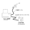
図2は、ホスト側機器と周辺機器との構成例を示した図である。図2に示すように、ホスト機器(プリンタ)10と周辺機器(カメラ)20とがUSBインターフェースケーブル30を介して接続されている。また、ホスト機器10の電源ケーブル13は、AC電源40に接続される。
【0039】
なお、図2では、ホスト側機器10として、プリンタを、周辺機器20としてデジタルカメラを用いて説明するが、これに限定されることなく、ホスト側機器10には、パーソナルコンピュータ、オーディオ機器、携帯電話、カメラ等の電源の供給をすることができる種々の機器が含まれる。また、周辺機器20には、携帯電話等の蓄電池を有する種々の機器が含まれる。
【0040】
図1に戻って、ホスト側機器10は、電源供給手段11と、MPU12と、トランシーバTR1と、プルダウン抵抗Rpdと、コンパレータCP1とを有する。周辺機器20は、スイッチSW1、SW2、SW3と、CPU21と、トランシーバTR2と、プルアップ抵抗Rpuと、レギュレータRG1と、蓄電池22とを有する。
【0041】
電源供給手段11は、USBのVbusを介して、周辺機器20のスイッチSW3の端子と、スイッチSW2の端子に接続されている。ここで、Vbus12は、USBの電源ラインであって、ホスト側装置10が周辺機器20に対して電源を供給するためのものである。
【0042】
トランシーバTR1は、USBの信号線を介して、周辺機器20のトランシーバTR2に接続され、トランシーバTR1から送信したデータをトランシーバTR2で受信し、トランシーバTR2から送信したデータをトランシーバTR1で受信し、交互にデータ通信を行う。トランシーバTR1は、MPU12に接続されている。なお、トランシーバTR1を含んでホスト側機器10のインターフェース手段が構成されている。
【0043】
プルダウン抵抗Rpdは、信号線と接地電位との間に接続されている。コンパレータCP1の反転入力端子には、基準電圧が印加されている。コンパレータCP1の非反転入力端子には、周辺機器20が内臓する蓄電池22の出力電圧をプルアップ抵抗Rpuとプルダウン抵抗Rpdで分圧した電圧が印加されている。コンパレータCP1の出力は、MPU12に接続されている。コンパレータCP1は、基準電圧よりも非反転入力端子への入力電圧が大きいとき、ハイレベルを出力し、小さいときはローレベルを出力する。
【0044】
MPU12は、ホスト側機器10全体を制御し、コンパレータCP1の出力を入力ポートで監視して、電源供給手段11を制御する。すなわち、MPU12は、周辺機器20の蓄電池22の充電状態に応じて、USBインターフェースケーブル30の電源ラインを介して周辺機器20に電源を供給するように、電源供給手段11を制御する。
【0045】
詳細には、MPU12は、コンパレータCP1の出力レベルがハイレベルのときは、充電池22の充電が不要であると判定し、電源供給手段11から周辺機器20への電源の供給を行わないように、電源供給手段11を制御する。一方、MPU12は、コンパレータCP1の出力がローレベルのときは、蓄電池22の充電が必要であると判定し、電源供給手段11から周辺機器20への電源を供給するように、電源供給手段11を制御する。
【0046】
MPU12は、周辺機器20との通信終了後に、周辺機器20の蓄電池22に電源を供給するように電源供給手段11を制御する。すなわち、MPU12は、周辺機器20とのインターフェースケーブルを介した通信の有無に応じて、周辺機器20の蓄電池22に電源を供給するように電源供給手段11を制御する。MPU12は、周辺機器20の蓄電池22の充電後に、前記外部機器への電源の供給を停止するように電源供給手段11を制御する。なお、図1の例では、コンパレータCP1、プルダウン抵抗Rpd、MPU12により電源供給装置側の充電レベル検出手段が構成されているが、この構成例には限定されない。
【0047】
次に、周辺機器20について説明すると、スイッチSW1、SW2、SW3は、CPU21により、そのオン/オフが制御される。プルアップ抵抗Rpuの一端は、スイッチSW1に接続されており、他端は、トランシーバTR2とトランシーバTR2との間の信号線に接続されている。トランシーバTR2を含んで周辺機器20側のインターフェース手段が構成されている。
【0048】
スイッチSW1の端子2は、スイッチSW2に接続されている。スイッチWS2の端子1は、レギュレータRG1を介して、スイッチSW2に接続されている。スイッチSW2の端子2は、電源ラインVbusを介して、ホスト側機器10の電源供給手段11に接続されている。スイッチSW2の端子1は、蓄電池22に接続されている。
【0049】
蓄電池22は、スイッチSW3、電源ラインVbusを介して、ホスト側機器10の電源供給手段11に接続されている。CPU21は、通信時、スイッチSW1を端子1に、スイッチSW2を端子22に、スイッチSW3をオープンに設定する。これにより、周辺機器20は、電源ラインVbusを介してホスト側機器10の電源供給手段11に接続され、ホスト側機器10からの電源の供給を受ける。
【0050】
CPU21は、通信終了後、スイッチSW1を端子2に、スイッチSW2を端子1に設定する。これにより、周辺機器20が内臓する蓄電池22の出力電圧をプルアップ抵抗Rpuとプルダウン抵抗Rpdで分圧することができ、コンパレータCP1の非反転入力端子に分圧した電圧を印加することができる。CPU21は、必要に応じて、スイッチSW3をオフ状態からオン状態にすることにより、電源供給手段11から電源ラインVbusを介して蓄電池22を充電することができる。
【0051】
次に、本実施の形態に係るホスト側機器の電源供給方法と、周辺機器20の充電方法について説明する。図3は、ホスト側機器の電源供給フローを示した図である。通信時、周辺機器20のCPU21は、スイッチSW1を端子1に、スイッチSW2を端子2に、スイッチSW3をオープンにセットする。これにより、周辺機器20は、電源ラインVbusを介してホスト側機器10の電源供給手段11に接続される。
【0052】
ステップS101において、ホスト側機器10の電源供給手段11は、周辺機器10へ電源供給を開始する。ステップS102において、MPU12は、トランシーバTR1を参照して、周辺機器20と通信中か否かを判定する。ステップS102において、MPU12は、現在、周辺機器10と通信中でないと判定した場合には、ステップS103に進み、MPU12は、周辺機器10への電源供給の継続が必要か否かを判定する。
【0053】
詳細には、周辺機器のCPU21は、ホスト側機器10との通信終了後に、スイッチSW1を端子2に、スイッチSW2を端子1に設定する。これにより、周辺機器20が内臓する蓄電池22の出力電圧をプルアップ抵抗Rpuとプルダウン抵抗Rpdで分圧することができ、コンパレータCP1の非反転入力端子に分圧した電圧を印加することができる。コンパレータCP1で、分圧した電圧と基準電圧を比較し、周辺機器20への電源供給の継続が必要か否かを判定する。
【0054】
コンパレータCP1は、基準電圧よりも非反転入力端子への入力電圧が大きいときは、ハイレベルを、小さいときはローレベルをMPU12へ出力する。MPU12は、コンパレータCP1の出力レベルがハイレベルのときは、周辺機器20への電源供給が必要でないと判定する。一方、MPU12は、コンパレータCP1の出力レベルがローレベルのときは、周辺機器20への電源供給が必要であると判定する。
【0055】
ステップS103において、MPU12は、周辺機器20への電源供給の継続が必要であると判定した場合には、周辺機器20への電源供給を継続する。周辺機器20のCPU21は、スイッチSW3をオン状態にすることにより、電源ラインVbusを介して供給された電源を元に、蓄電池22を充電することができる。一方、ステップS103において、MPU12は、周辺機器20の電源供給の継続が必要でないと判定した場合には、ステップS104において、周辺機器20への電源供給を終了する。
【0056】
MPU12は、コンパレータCP1の電圧が基準レベルを超えた時点で、電源ラインVbusをオフすることにより、充電完了後は、ホスト側装置10の省電力化を図ることができる。
【0057】
以上本実施の形態によれば、周辺機器20の蓄電池22の充電状態に応じて、USBインターフェースケーブル30の電源ラインVbusを介して周辺機器20に電源を供給するようにしたので、蓄電池22の残量が少ない周辺機器20は、USBインターフェースケーブル30を介して供給される電源をもとに、蓄電池22を充電することができる。これにより、蓄電池充電用の電源ケーブルを接続することなく、蓄電池22の充電をすることができる。
【0058】
また、外部機器の蓄電池の充電が不足している場合でも、インターフェースケーブルを介して供給する電源をもとに動作可能とすることができる。このように、ユーザの手を煩わすことなく、データ通信用のインターフェースケーブルを接続するだけで、蓄電池の残量が減少している時、蓄電池に充電を行うことができる。
【0059】
なお、図1に示した例では、ホスト側機器10が蓄電池22の電圧レベルを検出するようにしたが、CPU21が蓄電池22の電圧レベルを検出して、検出した電圧レベルをホスト側機器10のMPU12に出力するようにしてもよい。この場合、CPU21が電子機器側の電圧レベル検出手段に相当する。
【0060】
(第2の実施の形態)
次に、第2の実施の形態に係るホスト側機器と周辺機器について説明する。図4は、第2の実施の形態に係るホスト側機器と周辺機器の構成を示すブロック図である。図4に示すように、ホスト側機器110と、周辺機器120及びUSBインターフェースケーブル30により構成されている。
【0061】
ホスト側機器110は、USBインターフェースケーブル30を介して、周辺機器120に接続されている。周辺機器120は、ホスト側機器110から電源ラインVbusを介して、電源の供給を受けて、供給された電源により蓄電池を充電する。
【0062】
ホスト側機器110は、電源供給手段11と、MPU112と、トランシーバTR1とを有する。周辺機器120は、スイッチSW1、SW2、SW3と、CPU121と、トランシーバTR2と、レギュレータRG1と、蓄電池22とを有する。なお、図1と同一部分は同一符号を付するものとし、その説明を省略する。
【0063】
MPU112が周辺機器120から蓄電池22の充電要求を取得する取得手段に相当する。MPU112は、取得した蓄電池22の充電要求に応じて、USBインターフェースケーブル30の電源ラインVbusを介して周辺機器120に電源を供給するように電源供給手段11を制御する。
【0064】
CPU121は、ホスト側機器110に対して充電池22の充電要求をトランシーバTR2を介して送信する。また、CPU121は、蓄電池22の電圧レベルを参照して、蓄電池22の充電レベルを検出する。したがって、CPU21が充電レベル検出手段に相当する。なお、充電レベル検出手段はこの構成に限定されない。
【0065】
次に、第2の実施の形態に係るホスト側機器と周辺機器の処理に動作について説明する。図5は、第2の実施の形態に係るホスト側機器と周辺機器とのタイミングチャートである。以下、ホスト側機器110と周辺機器120のデータの送受信は、ホスト側機器110のMPU112と、周辺機器120のCPU121とが所定のプログラムを実行することにより行う。
【0066】
ステップS201において、ホスト側機器110は、「IsBatteryChargeAveil」のコマンドを周辺機器120へ出力し、周辺機器120が蓄電池の充電をサポートしているか否かを確認する。
【0067】
ステップS301において、このコマンドを受けた周辺機器120は、蓄電池の充電をサポートしている場合には「Yes」をホスト側機器110へ返す。一方、周辺機器120は、蓄電池22の充電をサポートしていない場合には「No」をホスト側機器110へ返す。
【0068】
ステップS202において、ホスト側機器110は、周辺機器120から「No」の返事を受け取った場合は、ステップS203において、電源ラインVbusをオフにする。これにより、電源供給手段11から周辺機器110へ蓄電池22への電源供給は行われない。
【0069】
一方、ステップS202において、ホスト側機器110は、周辺機器120から「Yes」の返事を受け取った場合には、ステップS204において、「IsBatteryChargeNecessary」のコマンドを周辺機器120へ出力し、蓄電池22の充電が必要か否かを確認する。
【0070】
ステップS302において、このコマンドを受けた周辺機器120は、蓄電池22の充電が必要であると判定した場合には、「Yes」をホスト側機器110へ返し、蓄電池22の充電が必要で無いと判定した場合には、「No」をホスト側機器110へ返す。
【0071】
つまり、このコマンドを受けた周辺機器120のCPU121は、蓄電池22の充電レベルを参照して、蓄電池22の充電レベルが所定基準レベル以上か否かを判定する。CPU121は、蓄電池22の充電レベルが所定基準レベル以下であると判定した場合には、充電が必要であると判断して、ホスト側機器110に「Yes」の返事を返す。CPU121は、ホスト側機器110に「Yes」の返事を返すと、スイッチSW3をオフ状態からオン状態に切り換える。
【0072】
一方、CPU121は、蓄電池22の充電レベルが所定基準レベル以上であると判定した場合には、充電が不要であると判断して、ホスト側機器110に「No」の返事を返す。
【0073】
ステップS205において、ホスト側機器110は、周辺機器120から「No」の返事を受け取った場合には、ステップS206において、電源ラインVbusをオフにする。つまり、MPU121は、「No」の返事をトランシーバTR1を介して受信すると、電源供給手段11から周辺機器120への電源の供給を停止する。一方、ステップS205において、ホスト側機器110は、周辺機器120から「Yes」の返事を受け取った場合には、ステップS207において、電源ラインVbusを保持して、周辺機器120の蓄電池22の充電が開始される。
【0074】
ステップS208において、ホスト側機器110は、「IsBatteryChargeNecessary」のコマンドを周辺機器120へ出力し、周辺機器120の蓄電池22の充電が必要か否かを確認する。
【0075】
ステップS303において、このコマンドを受けた周辺機器120は、蓄電池22の充電が必要な場合には、「Yes」をホスト側機器110へ返し、蓄電池22の充電が必要で無い場合には、「No」をホスト側機器110へ返す。つまり、このコマンドを受けた周辺機器120のCPU121は、蓄電池22の充電レベルを参照して、蓄電池22の充電レベルが所定基準レベル以上か否かを判定する。
【0076】
CPU121は、蓄電池22の充電レベルが所定基準レベル以下であると判定した場合には、充電池22の充電が必要であると判断して、ホスト側機器110に「Yes」の返事を返す。CPU121は、ホスト側機器110に「Yes」の返事を返す場合には、スイッチSW3のオン状態を維持する。一方、CPU121は、蓄電池22の充電が所定基準レベル以上であると判定した場合には、充電が不要であると判断して、ホスト側機器110に「No」の返事を返す。CPU121は、ホスト側機器110に「No」の返事を返す場合には、スイッチSW2をオン状態からオフ状態に切り換える。
【0077】
ステップS209において、ホスト側機器110は、周辺機器120から「Yes」の返事を受け取った場合には、ステップS210において、電源ラインVbusを保持して、周辺機器110への電源の供給を継続する。これにより、ホスト側装置110の電源供給手段11から周辺機器120の蓄電池22への電源の供給が継続される。
【0078】
一方、ステップS209において、ホスト側機器110は、周辺機器120から「No」の返事を受け取った場合は、ステップS211において、電源ラインVbusをオフにして、電源供給手段11から周辺機器110への電源の供給を停止する。これにより、周辺機器120の蓄電池22は充電が完了する。
【0079】
ステップS212において、ホスト側機器110は、「IsBatteryChargeNecessary」のコマンドを周辺機器120へ出力し、周辺機器120の蓄電池22の充電が必要か否かを確認する。ステップS304において、このコマンドを受けた周辺機器120は、蓄電池22の充電が必要で無い場合には、「No」をホスト側機器110へ返す。
【0080】
ステップS213において、ホスト側機器110は、周辺機器120から「No」の返事を受け取った場合は、電源ラインVbusをオフにして、周辺機器110への電源の供給を停止する。これにより、周辺機器120の蓄電池22は充電が完了する。
【0081】
以上本実施の形態によれば、取得した蓄電池22の充電要求に応じて、USBインターフェースケーブル30の電源ラインを介して周辺機器20に電源を供給するようにしたので、蓄電池の残量が少ない周辺機器20は、USBインターフェースケーブル30を介して供給される電源をもとに、蓄電池22を充電することができる。よって、蓄電池充電用の電源ケーブルを接続することなく、蓄電池22を充電することができる。
【0082】
以上本発明の好ましい実施の形態について詳述したが、本発明は係る特定の実施形態に限定されるものではなく、特許請求の範囲に記載された本発明の要旨の範囲内において、種々の変形・変更が可能である。
【0083】
【発明の効果】
以上説明したように、本発明によれば、電力消費を抑制しながら効率的に電子機器の有する蓄電池を充電できる電源供給装置及び電源供給方法、並びに電源を供給する電源供給装置における電力消費を抑制しながら効率的に蓄電池を充電できる電子機器を提供できる。
【図面の簡単な説明】
【図1】 第1の実施の形態に係るホスト側機器と周辺機器のブロック図である。
【図2】 ホスト側機器と周辺機器との構成例を示した図である。
【図3】 ホスト側機器の電源供給フローを示した図である。
【図4】 第2の実施の形態に係るホスト側機器と周辺機器のブロック図である。
【図5】 第2の実施の形態に係るホスト側機器と周辺機器とのタイミングチャートである。
【符号の説明】
10、110 ホスト側機器
11 電源供給手段
12、112 MPU
20、120 周辺機器
21、121 CPU
22 蓄電池
30 USBインターフェースケーブル
TR1、TR2 トランシーバ
CP1 コンパレータ
Rpd プルダウン抵抗
Rpu プルアップ抵抗
SW1、SW2、SW3 スイッチ
RG1 レギュレータ[0001]
BACKGROUND OF THE INVENTION
The present invention relates to a power supply device, an electronic device, a power supply method, and a charging method.
[0002]
[Prior art]
In recent years, the On-The-Go standard (USBOTG) has been defined as an additional specification of USB (Universal Serial Bus) 2.0. In this USBOTG, a device other than a personal computer that has been operable only as a USB peripheral device until now becomes a USB host and can communicate with the connected peripheral device.
[0003]
As a USBOTG host, an electronic device driven by a battery such as a PDA (Personal Digital Assistant) is also considered. For example, connecting a USB keyboard to the PDA facilitates input to the PDA. When such an electronic device driven by a battery supplies power to a peripheral device connected by USB OGT, the duration of the battery becomes a problem.
[0004]
Therefore, in USBOGT, when the communication with the peripheral device is completed, the power supply to the peripheral device is stopped, and the power supply is restarted when the next communication is started, thereby minimizing the battery duration. Yes.
[0005]
In addition, the following devices have been proposed for supplying power to peripheral devices. In the digital camera described in Patent Document 1, the internal power supply means and the external power supply input means are switched to supply power to each part of the device, thereby reducing the consumption of the internal power supply.
[0006]
In the apparatus described in Patent Document 2, the presence or absence of peripheral devices or the presence or absence of use is detected, the power of the interface controller is controlled, and the power consumption of the devices is reduced.
[0007]
[Patent Document 1]
JP 2002-94873 A
[Patent Document 2]
JP-A-7-302141
[Problems to be solved by the invention]
For example, in a printer, an application of USB OGT is possible in which an image can be printed out without using a personal computer by directly connecting a device such as a digital still camera storing digital images to the printer. Usually, the printer has an internal power supply and is not battery powered. On the other hand, digital still cameras are often battery-driven. If the USB OGT function is incorporated as it is, even when a printer and a digital still camera are connected, the power supply is stopped when the data transfer is completed.
[0008]
However, if the battery of the digital still camera is a storage battery, and the remaining amount of the battery is reduced and the user uses the digital still camera to take a picture after sending data to the printer, the digital still camera is charged with a storage battery. It was necessary to connect the power cable to the cable.
[0009]
In addition, since the digital camera described in Patent Document 1 uses an external power supply to charge a storage battery used for the internal power supply, it is necessary to connect a power cable for charging the storage battery.
[0010]
In addition, the apparatus described in Patent Document 2 cannot supply power after using peripheral devices.
[0011]
The present invention Power supply device and power supply method capable of efficiently charging storage battery of electronic device while suppressing power consumption, and electronic device capable of efficiently charging storage battery while suppressing power consumption in power supply device for supplying power The purpose is to provide.
[0012]
[Means for Solving the Problems]
In order to solve the above-described problem, the power supply device according to claim 1 includes an interface unit that communicates with an external device having a storage battery via an interface cable; After the interface means ends communication, the state of charge of the storage battery of the external device And a power supply means for supplying power to the external device via the interface cable.
[0013]
According to invention of Claim 1, After the interface means has finished communicating, the storage battery charge state of the external device In response to this, power is supplied to the external device via the interface cable, so an external device with a low remaining battery capacity can charge the storage battery based on the power supplied via the interface cable. Can do. Therefore, without connecting the power cable for charging the storage battery, External devices have efficiently while reducing power consumption The storage battery can be charged.
[0014]
According to a second aspect of the present invention, there is provided the power supply apparatus according to the first aspect, further comprising charge level detecting means for detecting a charge level of the storage battery of the external device. According to the invention described in claim 2, by detecting the charge level of the storage battery of the external device by the charge level detecting means, it is possible to supply power to the external device in accordance with the detected charge level.
[0015]
Further, the present invention provides the power supply apparatus according to claim 1, wherein the power supply unit is configured to change the storage battery of the external device acquired from the external device according to the charge level of the storage battery. It is characterized by supplying power to an external device. According to the third aspect of the present invention, power can be supplied to the external device according to the charge level of the storage battery acquired from the external device.
[0016]
Further, the power supply device according to claim 4, interface means for communicating with an external device having a storage battery via an interface cable, acquisition means for acquiring a charge request for the storage battery from the external device, After the interface means ends communication, And a power supply means for supplying power to the external device via the interface cable in response to the charging request of the storage battery acquired by the acquisition means.
[0017]
According to invention of Claim 4, After the interface means ends communication, Since power is supplied to the external device via the interface cable in response to the acquired charging request for the storage battery, the external device with a low remaining capacity of the storage battery is based on the power supplied via the interface cable. The storage battery can be charged. Therefore, without connecting the power cable for charging the storage battery, External devices have efficiently while reducing power consumption The storage battery can be charged.
[0018]
In addition, the present invention The The power supply device according to any one of claims 1 to 4. Is The power supply means supplies power to the storage battery of the external device after communication with the external device is completed. For, Power can be supplied to the external device during communication, and power can be supplied to the charger of the external device after communication.
[0019]
The present invention also includes claims. 5 Claims 1 to 4 In the power supply device according to any one of the above, the power supply unit stops supplying power to the external device after charging the storage battery of the external device. Claim 5 According to the described invention, since the supply of power to the external device is stopped after the storage battery of the external device is charged, power consumption can be reduced.
[0020]
Claims 6 The described power supply apparatus includes an interface unit that communicates with an external device having a storage battery via an interface cable; After the interface means ends communication According to the state of charge of the storage battery of the external device, the power supply means for supplying power to the external device via the interface cable, a comparator, and a pull-down resistor, a reference input to the inverting input terminal of the comparator A voltage is applied, and a voltage obtained by dividing the output voltage of the storage battery of the external device by a pull-up resistor and the pull-down resistor is applied to the non-inverting input terminal of the comparator, and according to the output of the comparator, Power is supplied from the power supply means to the external device.
[0021]
Claims 7 The electronic device described includes an interface unit that communicates with a host-side device via an interface cable, and a storage battery. After the interface means finishes communication, the state of charge of the storage battery In response to this, power is supplied from the host device via the interface cable.
[0022]
Claim 7 According to the described invention, After the interface means finishes communication, the state of charge of the storage battery Depending on the situation, power is supplied from the host side device via the interface cable, so when the remaining capacity of the storage battery is low, the storage battery is charged based on the power supplied via the interface cable. be able to. Therefore, without connecting the power cable for charging the storage battery, Efficiently while suppressing power consumption in the host device The storage battery can be charged.
[0023]
Claims 8 The electronic device described includes an interface unit that communicates with a host side device via an interface cable, a storage battery, and a transmission unit that transmits a charge request for the rechargeable battery to the host side device, After the interface means ends communication, In response to a request for charging the storage battery transmitted by the transmission means, power is supplied from the host device via the interface cable.
[0024]
Claim 8 According to the described invention, After the interface means ends communication, In response to the storage battery charging request transmitted by the transmission means, the power supply is received from the host device via the interface cable, so the storage battery is charged based on the power supplied via the interface cable. be able to. Therefore, without connecting the power cable for charging the storage battery, Efficiently while suppressing power consumption in the host device The storage battery can be charged.
[0025]
Claims 9 The electronic device described is a claim 7 Or claim 8 The electronic device described above further includes a charge level detection unit that detects a charge level of the storage battery. Claim 9 According to the described invention, power can be supplied from an external device in accordance with the charge level detected by the charge level detection means.
[0026]
An electronic device according to
[0027]
[0028]
[0029]
[0030]
[0031]
Claims 13 The power supply method described is a power supply method for supplying power to a storage battery of an external device, An interface step for communicating with the external device via an interface cable; An acquisition step of acquiring a charge request for the storage battery from the external device; After terminating communication in the interface step, And a power supply step of supplying power to the storage battery of the external device via an interface cable in response to the charge request of the storage battery acquired in the acquisition step.
[0032]
Claim 13 According to the described invention, After ending communication Since power is supplied to the external device via the interface cable in response to the acquired charging request for the storage battery, the external device with a low remaining capacity of the storage battery is based on the power supplied via the interface cable. The storage battery can be charged. Therefore, without connecting the power cable for charging the storage battery, External devices have efficiently while reducing power consumption The storage battery can be charged.
[0033]
Claims 14 The described charging method is a charging method for charging a storage battery by receiving power supply from a host side device, An interface step of communicating with the host side device via an interface cable; A charge level detecting step for detecting the charge level of the storage battery; a transmission step for transmitting the charge level of the storage battery detected by the charge level detection step to the host side device; After terminating communication in the interface step, A charging step of charging the storage battery by receiving power supply from the host side device via an interface cable according to the charge level of the storage battery transmitted in the transmission step.
[0034]
Claim 14 According to the described invention, After ending communication Depending on the charge level of the storage battery transmitted in the transmission step, the storage battery can be charged by receiving power supply from the host side device via the interface cable. Therefore, without connecting the power cable for charging the storage battery, Efficiently while suppressing power consumption of the host side device The storage battery can be charged.
[0035]
The charging method according to claim 15 is a charging method for charging a storage battery by receiving power supply from a host side device, An interface step of communicating with the host side device via an interface cable; A transmission step of transmitting a charge request for the rechargeable battery to the host device; After terminating communication in the interface step, A charging step of charging the storage battery by receiving a supply of power from the external host side device via an interface cable in response to the charging request of the rechargeable battery transmitted in the transmitting step.
[0036]
Claim 15 According to the described invention, After ending communication In response to the request for charging the rechargeable battery, the storage battery is charged by receiving power from the external host side device via the interface cable. Based on the power supplied via the interface cable, The storage battery can be charged. Therefore, without connecting the power cable for charging the storage battery, Efficiently while suppressing power consumption of the host side device The storage battery can be charged.
[0037]
DETAILED DESCRIPTION OF THE INVENTION
(First embodiment)
Hereinafter, embodiments of the present invention will be described in detail with reference to the drawings. FIG. 1 is a block diagram of a host device and peripheral devices. As shown in FIG. 1, the
[0038]
FIG. 2 is a diagram illustrating a configuration example of the host side device and the peripheral device. As shown in FIG. 2, a host device (printer) 10 and a peripheral device (camera) 20 are connected via a
[0039]
In FIG. 2, a printer is used as the host-
[0040]
Returning to FIG. 1, the host-
[0041]
The power supply means 11 is connected to the terminal of the switch SW3 of the
[0042]
The transceiver TR1 is connected to the transceiver TR2 of the
[0043]
The pull-down resistor Rpd is connected between the signal line and the ground potential. A reference voltage is applied to the inverting input terminal of the comparator CP1. A voltage obtained by dividing the output voltage of the storage battery 22 incorporated in the
[0044]
The
[0045]
Specifically, when the output level of the comparator CP1 is high, the
[0046]
The
[0047]
Next, the
[0048]
A terminal 2 of the switch SW1 is connected to the switch SW2. The terminal 1 of the switch WS2 is connected to the switch SW2 via the regulator RG1. The terminal 2 of the switch SW2 is connected to the power supply means 11 of the
[0049]
The storage battery 22 is connected to the power supply means 11 of the host-
[0050]
After completing the communication, the
[0051]
Next, a method for supplying power to the host side device and a method for charging the
[0052]
In step S <b> 101, the
[0053]
Specifically, the
[0054]
The comparator CP1 outputs a high level to the
[0055]
In step S <b> 103, when the
[0056]
When the voltage of the comparator CP1 exceeds the reference level, the
[0057]
As described above, according to the present embodiment, power is supplied to the
[0058]
In addition, even when the storage battery of the external device is insufficiently charged, it can be operated based on the power supplied through the interface cable. In this way, the battery can be charged when the remaining amount of the storage battery is reduced simply by connecting the interface cable for data communication without bothering the user.
[0059]
In the example shown in FIG. 1, the host-
[0060]
(Second Embodiment)
Next, a host side device and peripheral devices according to the second embodiment will be described. FIG. 4 is a block diagram illustrating configurations of a host device and peripheral devices according to the second embodiment. As shown in FIG. 4, the
[0061]
The
[0062]
The
[0063]
The
[0064]
The
[0065]
Next, the operation of the host side device and the peripheral device according to the second embodiment will be described. FIG. 5 is a timing chart of the host side device and the peripheral device according to the second embodiment. Hereinafter, transmission / reception of data between the
[0066]
In step S201, the host-
[0067]
In step S <b> 301, the
[0068]
In step S202, when the host-
[0069]
On the other hand, if the host-
[0070]
In step S302, if the
[0071]
That is, the
[0072]
On the other hand, if the
[0073]
In step S205, when the host-
[0074]
In step S <b> 208, the host-
[0075]
In step S303, the
[0076]
When the
[0077]
In step S209, when the host-
[0078]
On the other hand, if the
[0079]
In step S212, the host-
[0080]
In step S <b> 213, when the host-
[0081]
As described above, according to the present embodiment, power is supplied to the
[0082]
Although the preferred embodiment of the present invention has been described in detail above, the present invention is not limited to the specific embodiment, and various modifications are possible within the scope of the gist of the present invention described in the claims.・ Change is possible.
[0083]
【The invention's effect】
As explained above, according to the present invention, Power supply device and power supply method capable of efficiently charging storage battery of electronic device while suppressing power consumption, and electronic device capable of efficiently charging storage battery while suppressing power consumption in power supply device for supplying power Can be provided.
[Brief description of the drawings]
FIG. 1 is a block diagram of a host device and peripheral devices according to a first embodiment.
FIG. 2 is a diagram illustrating a configuration example of a host device and peripheral devices.
FIG. 3 is a diagram showing a power supply flow of a host side device.
FIG. 4 is a block diagram of a host side device and peripheral devices according to a second embodiment.
FIG. 5 is a timing chart of host-side devices and peripheral devices according to the second embodiment.
[Explanation of symbols]
10, 110 Host side equipment
11 Power supply means
12, 112 MPU
20, 120 Peripheral devices
21, 121 CPU
22 Storage battery
30 USB interface cable
TR1, TR2 transceiver
CP1 comparator
Rpd pull-down resistor
Rpu pull-up resistor
SW1, SW2, SW3 switch
RG1 regulator
Claims (15)
前記インターフェース手段が通信を終了した後に、前記外部機器の前記蓄電池の充電状態に応じて、前記インターフェースケーブルを介して前記外部機器に電源を供給する電源供給手段とを有することを特徴とする電源供給装置。Interface means for communicating with an external device having a storage battery via an interface cable;
After the interface unit has completed the communication, in accordance with the state of charge of the battery of the external device, power supply and having a power supply means for supplying power to the external device via the interface cable apparatus.
前記外部機器から前記蓄電池の充電要求を取得する取得手段と、
前記インターフェース手段が通信を終了した後に、前記取得手段が取得した前記蓄電池の充電要求に応じて、前記インターフェースケーブルを介して前記外部機器に電源を供給する電源供給手段とを有することを特徴とする電源供給装置。Interface means for communicating with an external device having a storage battery via an interface cable;
Obtaining means for obtaining a charge request for the storage battery from the external device;
A power supply unit configured to supply power to the external device via the interface cable in response to a charge request for the storage battery acquired by the acquisition unit after the interface unit ends communication; Power supply device.
前記インターフェース手段が通信を終了した後に、前記外部機器の前記蓄電池の充電状態に応じて、前記インターフェースケーブルを介して前記外部機器に電源を供給する電源供給手段と、
コンパレータと、プルダウン抵抗とを備え、
前記コンパレータの反転入力端子には、基準電圧が印加され、前記コンパレータの非反転入力端子には、前記外部機器の前記蓄電池の出力電圧をプルアップ抵抗と前記プルダウン抵抗とで分圧した電圧が印加され、前記コンパレータの出力に応じて、前記電源供給手段から前記外部機器へ電源を供給することを特徴とする電源供給装置。Interface means for communicating with an external device having a storage battery via an interface cable;
After the interface unit has completed the communication, in accordance with the state of charge of the battery of the external device, and a power supply means for supplying power to the external device via the interface cable,
Comparator and pull-down resistor
To the inverting input terminal of the comparator is a reference voltage is applied to the non-inverting input terminal of the comparator, the voltage output voltage divided by pull-up resistor and the pull-down resistor of the battery of the external device is applied And supplying power from the power supply means to the external device in accordance with the output of the comparator.
蓄電池とを備え、
前記インターフェース手段が通信を終了した後に、前記蓄電池の充電状態に応じて、前記インターフェースケーブルを介して前記ホスト側機器から電源の供給を受けることを特徴とする電子機器。Interface means for communicating with the host side device via an interface cable;
A storage battery,
An electronic device characterized in that, after the interface means ends communication, power is supplied from the host side device via the interface cable in accordance with the state of charge of the storage battery.
蓄電池と、
前記蓄電池の充電要求を前記ホスト側機器に対して送信する送信手段とを備え、
前記インターフェース手段が通信を終了した後に、前記送信手段により送信した前記蓄電池の充電要求に応じて、前記インターフェースケーブルを介して前記ホスト側機器から電源の供給を受けることを特徴とする電子機器。Interface means for communicating with the host side device via an interface cable;
A storage battery,
Transmission means for transmitting a charge request for the storage battery to the host side device,
An electronic device characterized in that, after the interface unit ends communication, the host side device receives power supply via the interface cable in response to a request for charging the storage battery transmitted by the transmission unit.
前記外部機器との間でインターフェースケーブルを介して通信を行うインターフェースステップと、
前記外部機器の前記蓄電池の充電レベルを検出する充電レベル検出ステップと、
前記インターフェースステップで通信を終了した後に、前記充電レベル検出ステップにより検出した前記外部機器の前記蓄電池の充電レベルに応じて、前記インターフェースケーブルを介して前記外部機器の前記蓄電池へ電源を供給する電源供給ステップとを有することを特徴とする電源供給方法。A power supply method for supplying power to a storage battery of an external device,
An interface step for communicating with the external device via an interface cable;
A charge level detecting step of detecting the charge level of the battery of the external device,
After finishing the communication in said interface step, depending on the charge level of the battery of the external device detected by the charge level detecting step, the power supply supplies power through the interface cable to the storage battery of the external device And a power supply method.
前記外部機器との間でインターフェースケーブルを介して通信を行うインターフェースステップと、
前記外部機器の前記蓄電池の充電レベルを前記外部機器から取得する充電レベル取得ステップと、
前記インターフェースステップで通信を終了した後に、前記充電レベル取得ステップにより取得した前記外部機器の前記蓄電池の充電レベルに応じて、前記インターフェースケーブルを介して前記外部機器の前記蓄電池へ電源を供給する電源供給ステップとを有することを特徴とする電源供給方法。A power supply method for supplying power to a storage battery of an external device,
An interface step for communicating with the external device via an interface cable;
A charge level acquiring the charge level of the battery of the external device from the external device,
After finishing the communication in said interface step, depending on the charge level of the battery of the external device obtained by the charge level acquiring step, the power supply supplies power through the interface cable to the storage battery of the external device And a power supply method.
前記外部機器との間でインターフェースケーブルを介して通信を行うインターフェースステップと、
前記外部機器から前記蓄電池の充電要求を取得する取得ステップと、
前記インターフェースステップで通信を終了した後に、前記取得ステップにより取得した前記蓄電池の充電要求に応じて、前記インターフェースケーブルを介して前記外部機器の前記蓄電池へ電源を供給する電源供給ステップとを有することを特徴とする電源供給方法。A power supply method for supplying power to a storage battery of an external device,
An interface step for communicating with the external device via an interface cable;
An acquisition step of acquiring a charge request for the storage battery from the external device;
After finishing the communication in said interface step, in response to the charge request of the battery acquired by the acquisition step, to have a power supply supplying power to the battery of the external device via the interface cable A power supply method characterized.
前記ホスト側機器との間でインターフェースケーブルを介して通信を行うインターフェースステップと、
前記蓄電池の充電レベルを検出する充電レベル検出ステップと、
前記充電レベル検出ステップにより検出した前記蓄電池の充電レベルを前記ホスト側機器に送信する送信する送信ステップと、
前記インターフェースステップで通信を終了した後に、前記送信ステップにより送信した前記蓄電池の充電レベルに応じて、前記インターフェースケーブルを介して前記ホスト側機器から電源の供給を受けて前記蓄電池を充電する充電ステップとを有することを特徴とする充電方法。A charging method for charging a storage battery by receiving power supply from a host side device,
An interface step of communicating with the host side device via an interface cable;
A charge level detecting step for detecting a charge level of the storage battery;
A transmission step of transmitting the charge level of the storage battery detected by the charge level detection step to the host side device;
After finishing the communication in the interface step, a charging step in response to the charge level of the battery that transmitted by said transmitting step, to charge the storage battery is supplied with power from the host side device through the interface cable A charging method characterized by comprising:
前記ホスト側機器との間でインターフェースケーブルを介して通信を行うインターフェースステップと、
前記蓄電池の充電要求を前記ホスト側機器に対して送信する送信ステップと、
前記インターフェースステップで通信を終了した後に、前記送信ステップにより送信した前記蓄電池の充電要求に応じて、前記インターフェースケーブルを介して前記外部ホスト側機器から電源の供給を受けて前記蓄電池を充電する充電ステップとを有することを特徴とする充電方法。A charging method for charging a storage battery by receiving power supply from a host side device,
An interface step of communicating with the host side device via an interface cable;
A transmission step of transmitting a charge request for the storage battery to the host side device;
After finishing the communication in the interface step, charging steps according to the charging request for the storage battery has been transmitted by the transmission step, to charge the battery by receiving power from the external host device via the interface cable The charging method characterized by having.
Priority Applications (1)
| Application Number | Priority Date | Filing Date | Title |
|---|---|---|---|
| JP2003079585A JP4329371B2 (en) | 2003-03-24 | 2003-03-24 | Power supply device, electronic device, power supply method and charging method |
Applications Claiming Priority (1)
| Application Number | Priority Date | Filing Date | Title |
|---|---|---|---|
| JP2003079585A JP4329371B2 (en) | 2003-03-24 | 2003-03-24 | Power supply device, electronic device, power supply method and charging method |
Publications (2)
| Publication Number | Publication Date |
|---|---|
| JP2004287887A JP2004287887A (en) | 2004-10-14 |
| JP4329371B2 true JP4329371B2 (en) | 2009-09-09 |
Family
ID=33293658
Family Applications (1)
| Application Number | Title | Priority Date | Filing Date |
|---|---|---|---|
| JP2003079585A Expired - Lifetime JP4329371B2 (en) | 2003-03-24 | 2003-03-24 | Power supply device, electronic device, power supply method and charging method |
Country Status (1)
| Country | Link |
|---|---|
| JP (1) | JP4329371B2 (en) |
Families Citing this family (4)
| Publication number | Priority date | Publication date | Assignee | Title |
|---|---|---|---|---|
| EP2073337A1 (en) | 2006-10-11 | 2009-06-24 | Panasonic Corporation | Electronic device and charging control method |
| JP5303814B2 (en) * | 2009-06-29 | 2013-10-02 | オンキヨー株式会社 | Electronic device and adapter device |
| KR101717505B1 (en) * | 2010-12-02 | 2017-03-17 | 삼성전자주식회사 | Method for Charging External Device and Displaying Apparatus using thereof |
| CN103365388B (en) * | 2012-04-09 | 2017-02-22 | 华为终端有限公司 | Power supply method of terminal device and terminal device |
-
2003
- 2003-03-24 JP JP2003079585A patent/JP4329371B2/en not_active Expired - Lifetime
Also Published As
| Publication number | Publication date |
|---|---|
| JP2004287887A (en) | 2004-10-14 |
Similar Documents
| Publication | Publication Date | Title |
|---|---|---|
| US9979224B2 (en) | Integrated circuit for wireless charging and operating method thereof | |
| US7984318B2 (en) | Apparatus and method to support USB enumeration of a bus powered handheld device | |
| JP4144891B2 (en) | Method and apparatus for handling state of charge in a mobile electronic device | |
| US8084987B2 (en) | USB port with smart power management | |
| US9665150B2 (en) | Electronic device with a control circuit to detect and establish a connection to host device | |
| US20100109602A1 (en) | Charging device and method of operating the same | |
| EP1775652B1 (en) | Apparatus and method to support USB enumeration of a BUS powered handheld device | |
| US20030109218A1 (en) | Portable wireless storage unit | |
| US20050208963A1 (en) | Cellular radio telephone set | |
| JP2005287278A (en) | Device and method for controlling charge of electronic terminal | |
| KR100972271B1 (en) | Integrated circuit and signal processing device using the same | |
| KR101729511B1 (en) | Computer system and control method thereof | |
| US20140019416A1 (en) | Mobile power supply with data backup function and data recovery method thereof | |
| WO2023197699A1 (en) | Charging circuit, charging control method and electronic device | |
| KR102138642B1 (en) | Integrated circuit for wireless power charging and method for operating the integrated circuit | |
| US20130061079A1 (en) | Image processing apparatus, method for controlling the same and storage medium | |
| JP4329371B2 (en) | Power supply device, electronic device, power supply method and charging method | |
| KR101835007B1 (en) | Apparatus and mathod for controlling charge current in portable terminal | |
| US20170063105A1 (en) | Charging method, charging controller and charging system | |
| JP2001160839A (en) | Electronic device and electronic device system and communication control method | |
| US20120212057A1 (en) | Portable device and image recording device | |
| TW201710831A (en) | Power bank apparatus and power control method thereof | |
| JP5251317B2 (en) | Device equipment, host equipment and interface system | |
| JP2001034367A (en) | Connection device | |
| JP2004118343A (en) | Electronic apparatus |
Legal Events
| Date | Code | Title | Description |
|---|---|---|---|
| A621 | Written request for application examination |
Free format text: JAPANESE INTERMEDIATE CODE: A621 Effective date: 20060221 |
|
| A977 | Report on retrieval |
Free format text: JAPANESE INTERMEDIATE CODE: A971007 Effective date: 20081121 |
|
| A131 | Notification of reasons for refusal |
Free format text: JAPANESE INTERMEDIATE CODE: A131 Effective date: 20081202 |
|
| A521 | Request for written amendment filed |
Free format text: JAPANESE INTERMEDIATE CODE: A523 Effective date: 20090130 |
|
| A131 | Notification of reasons for refusal |
Free format text: JAPANESE INTERMEDIATE CODE: A131 Effective date: 20090310 |
|
| A521 | Request for written amendment filed |
Free format text: JAPANESE INTERMEDIATE CODE: A523 Effective date: 20090428 |
|
| TRDD | Decision of grant or rejection written | ||
| A01 | Written decision to grant a patent or to grant a registration (utility model) |
Free format text: JAPANESE INTERMEDIATE CODE: A01 Effective date: 20090526 |
|
| A01 | Written decision to grant a patent or to grant a registration (utility model) |
Free format text: JAPANESE INTERMEDIATE CODE: A01 |
|
| A61 | First payment of annual fees (during grant procedure) |
Free format text: JAPANESE INTERMEDIATE CODE: A61 Effective date: 20090608 |
|
| R150 | Certificate of patent or registration of utility model |
Ref document number: 4329371 Country of ref document: JP Free format text: JAPANESE INTERMEDIATE CODE: R150 Free format text: JAPANESE INTERMEDIATE CODE: R150 |
|
| FPAY | Renewal fee payment (event date is renewal date of database) |
Free format text: PAYMENT UNTIL: 20120626 Year of fee payment: 3 |
|
| FPAY | Renewal fee payment (event date is renewal date of database) |
Free format text: PAYMENT UNTIL: 20120626 Year of fee payment: 3 |
|
| FPAY | Renewal fee payment (event date is renewal date of database) |
Free format text: PAYMENT UNTIL: 20130626 Year of fee payment: 4 |
|
| FPAY | Renewal fee payment (event date is renewal date of database) |
Free format text: PAYMENT UNTIL: 20140626 Year of fee payment: 5 |
|
| S533 | Written request for registration of change of name |
Free format text: JAPANESE INTERMEDIATE CODE: R313533 |
|
| R350 | Written notification of registration of transfer |
Free format text: JAPANESE INTERMEDIATE CODE: R350 |
|
| EXPY | Cancellation because of completion of term |