EP3477426B1 - Computer system, client device and display device - Google Patents
Computer system, client device and display device Download PDFInfo
- Publication number
- EP3477426B1 EP3477426B1 EP18153267.2A EP18153267A EP3477426B1 EP 3477426 B1 EP3477426 B1 EP 3477426B1 EP 18153267 A EP18153267 A EP 18153267A EP 3477426 B1 EP3477426 B1 EP 3477426B1
- Authority
- EP
- European Patent Office
- Prior art keywords
- client device
- display device
- state
- power
- display
- Prior art date
- Legal status (The legal status is an assumption and is not a legal conclusion. Google has not performed a legal analysis and makes no representation as to the accuracy of the status listed.)
- Active
Links
Images


Classifications
-
- G—PHYSICS
- G06—COMPUTING; CALCULATING OR COUNTING
- G06F—ELECTRIC DIGITAL DATA PROCESSING
- G06F1/00—Details not covered by groups G06F3/00 - G06F13/00 and G06F21/00
- G06F1/26—Power supply means, e.g. regulation thereof
- G06F1/266—Arrangements to supply power to external peripherals either directly from the computer or under computer control, e.g. supply of power through the communication port, computer controlled power-strips
-
- G—PHYSICS
- G06—COMPUTING; CALCULATING OR COUNTING
- G06F—ELECTRIC DIGITAL DATA PROCESSING
- G06F1/00—Details not covered by groups G06F3/00 - G06F13/00 and G06F21/00
- G06F1/26—Power supply means, e.g. regulation thereof
- G06F1/32—Means for saving power
- G06F1/3203—Power management, i.e. event-based initiation of a power-saving mode
- G06F1/3206—Monitoring of events, devices or parameters that trigger a change in power modality
- G06F1/3215—Monitoring of peripheral devices
- G06F1/3218—Monitoring of peripheral devices of display devices
-
- G—PHYSICS
- G06—COMPUTING; CALCULATING OR COUNTING
- G06F—ELECTRIC DIGITAL DATA PROCESSING
- G06F13/00—Interconnection of, or transfer of information or other signals between, memories, input/output devices or central processing units
- G06F13/38—Information transfer, e.g. on bus
- G06F13/42—Bus transfer protocol, e.g. handshake; Synchronisation
- G06F13/4282—Bus transfer protocol, e.g. handshake; Synchronisation on a serial bus, e.g. I2C bus, SPI bus
-
- H—ELECTRICITY
- H04—ELECTRIC COMMUNICATION TECHNIQUE
- H04L—TRANSMISSION OF DIGITAL INFORMATION, e.g. TELEGRAPHIC COMMUNICATION
- H04L12/00—Data switching networks
- H04L12/02—Details
- H04L12/10—Current supply arrangements
Definitions
- the present invention relates to a computer system comprising a client device, for example a thin client PC, and a display device, for example a flat screen display device, operationally connected to the client device.
- a client device for example a thin client PC
- a display device for example a flat screen display device
- the present application relates to continuous power delivery from a display device to a client computing device.
- a display device 3 When a display device 3 is connected to an operating power (event E1), the display device 3 first enters a "start state" (state S1).
- a LCD monitor with an internal power supply unit can be plugged into a mains socket using an AC mains cable.
- an external power supply for the display device may be connected with a mains socket and the display device using corresponding AC and/or DC plug connectors.
- the display device 3 After the user presses a power button 7 to switch the display device 3 on, the display device 3 will first change into an "initial state" (state S3), in which internal control components of the display device 3 are initialized.
- a scaler 25 will initialize scaler registers and panel parameters for the display device 3.
- the display device 3 enters a "cable detection state" (state S4).
- state S4 the display device 3 determines whether it is connected to a client device 2.
- the display device detects whether a USB Type-C cable is connected to a corresponding plug connecter of the display device 3.
- Different types of connections can be detected.
- a USB connection to a compatible client device e.g. a client device of a given manufacturer such as Fujitsu Technology or Fujitsu Limited
- a USB connection to an incompatible client device e.g. a client device of another manufacturer, can be detected (event E3).
- the detection result is established and stored within a scaler register for later use as detailed below.
- the display device 3 enters a "signal search state" (state S5).
- the monitor tries to find a valid signal and prepares the display device 3 to output a found signal.
- the display device 3 may also identify which of a plurality of possible signal sources is connected to the display device 3.
- Power management circuitry of conventional display devices tries to deactivate as many internal components as possible, at least during a switched-off mode and an energy-saving mode, in order to reduce a power consumption.
- external interfaces such as a USB interface provided by a conventional display device are deactivated.
- the display device is used to supply an operating energy to a client system, for example via a full-featured USB Type-C interface and/or a USB power delivery function, this may result in an unintended disruption of the operating power of the client system.
Description
- The present invention relates to a computer system comprising a client device, for example a thin client PC, and a display device, for example a flat screen display device, operationally connected to the client device. Specifically, the present application relates to continuous power delivery from a display device to a client computing device.
- A typical workplace is equipped with a client computing device such as a thin client, a personal computer (PC), a notebook, a tablet, a smart phone, etc. and a display device. Both devices are connected to each other with several cables and by respective power cables to a mains power supply.
- Using the new, full-featured USB Type-C, in principle, it is possible to minimize the cabling between a display device and a notebook by using a single cable for data, video signal and also for power delivery from the display device to the client device. However, up to now, powering a client device by a display device is only possible if the display device is in an active state.
- If the display device goes to a power-saving mode, for example after a certain period of absence of the user, or is turned off by manually by pressing the display's power button, the display device will disable its main components and therefore also disconnect the client device, including the provision of power to the client device. In the worst case, if the client device is a PC or Thin Client, or generally a non-mobile device not equipped with a battery, then data of the client device could get lost because of a so-called "AC fail" condition, that is to say an unexpected shutdown of the client device. This could even happen with battery-equipped mobile devices, if they stay unpowered for a long period of time in a standby mode, by emptying the battery of the mobile device.
- Therefore, at present, such docking type displays, which are equipped with a USB Type-C interface and capable of implementing a power delivery technology, are defined and specified as charging devices for mobiles, tablets and notebooks only. However, they do not support an uninterruptable power delivery to a client device for seamless operation in all power state conditions.
-
WO 2017/184159 A1 relates to a display device power mode. The first time a display device is turned on, is turned on after it has been factory reset, or is factory reset, the display device displays a message indicating that in a default and current power mode of the display device, a hardware component of the display device different than display hardware is powered off when the display device enters a low-power state. A user is permitted to have the hardware component remain powered on when the display device enters the low-power state. -
US 2014/0164805 A1 relates to a data processing apparatus operating in a first power mode and a second power mode in which power consumption is lower than that of the first power mode, which includes a plurality of USB interfaces, a selection unit configured to select at least one of the USB interfaces which is to be used when the second power mode is entered, and a control unit configured to perform control so that, in the second power mode, electric power is supplied to a device connected to the at least one of the USB interfaces selected by the selection unit through the at least one of the USB interfaces. -
US 2017/0017283 A1 discloses a display apparatus including a display configured to display an image; a connecting section configured to connect with an external apparatus that includes at least one operating section and a charging section to be charged with power to be supplied to the operating section; a power supply configured to supply power to the external apparatus connected to the connecting section; and a controller configured to receive information about power used by at least one operating section of the external apparatus connected to the connecting section, determine a level of power supplied to the external apparatus according to the received power information and usage power of the display, and control the power supply to supply power having the determined level to the external apparatus. -
US 2015/0249356 A1 provides a method for charging an external device and a display using the method. The method includes, determining whether the external device is chargeable and connected to the display through a connector when the displaying apparatus is in a standby mode; and if it is determined that the external device is chargeable and connected, charging the external device through the connector in the standby mode. The display includes a power supply that supplies standby power or main power; a checker which determines, in a standby mode, whether an external device is connected and chargeable; and a controller. The controller controls the power supply to output standby power while the checker determines whether the external device is connected and is a chargeable device, and if the external device is connected and chargeable, controls the power supply to output main power to charge the external device. - The inventors have found out that the reason for this lack of support is that conventional display devices will go to a power-saving mode after detecting a "no signal found" condition or after the power button is pressed, in which cases internal components such as a power delivery controller will be disabled to fulfil lower power consumption requirements in a sleep or switched-off state by default, for example as defined by the Energy Star Display Specifications Version 7.
- The invention is defined by the attached set of claims. Embodiments which do not fall within the scope of the claims do not describe part of the present invention.
- A computer system is disclosed, comprising a client device, wherein the client device is a client computing device acting as a source for a display signal, and a display device operationally connected to the client device and acting as a sink for the display signal. Therein, the display device is configured to provide the client device with an operating energy, and the display device is further configured to detect a type of the client device, and, in case the client device belongs to a predefined group of client devices, to provide the display device with an operating energy even if the display device enters an energy-saving mode or is switched off.
- In order to overcome the above problems and shortcomings, the client device, for example a small form factor PC, thin client or notebook, will be continuously powered by the display device if it is detected to belong to a predetermined group of devices by the display device, for example as a thin client device and/or a Fujitsu device, independently from the current client device's and display device's power state.
- According to at least one embodiment, when connecting the client device to the display device, a handshaking process of the "power delivery" capable devices will be initiated to define a mutual power delivery level, for example 60 Watt using a provided operating voltage of 20 Volt at a current of 3 Ampere from the display device.
- During the handshaking process, the display device will determine the client device's vendor ID (VID), in some context also referred to a standard or vendor ID (SVID), and/or product ID (PID) by using so-called vendor-defined messages (VDM) specified in the power delivery specification of the respective interface. For details in this regard, reference is made to the related specifications under www.usb.org, and in particular to the USB Power Delivery Specification Revision 2.0 and Revision 3.0.
- If the display device determines a specific SVID or VID/PID combination, indicating that it is a Fujitsu device, then the display device will not go to a conventional sleep state, but rather it will keep the power delivery component alive to ensure continuous power delivery to the connected Fujitsu client device.
- This ensures a seamless operation of predetermined devices, for example non-battery equipped Fujitsu client devices, even though the display device will go to a corresponding "light sleep state" if no active video signal is found, or even if the display device is turned off manually by the end user by pressing its power button.
- Further advantageous embodiments of the present invention are defined in the attached set of claims.
- The invention will be described in more detail below using the attached figures. Therein, similar components of different embodiments are identified using the same reference numerals. In the figures:
-
Figure 1 shows a block diagram of a computer system according to an embodiment of the present invention; -
Figure 2 shows a block diagram of power delivery components according to an embodiment of the present invention; -
Figure 3 shows an extended state diagram of a display device according to an embodiment of the present invention; -
Figure 4 shows a flowchart of a handshaking process together with some of the data exchanged in accordance with an embodiment of the present invention; and -
Figure 5 shows a flowchart of an operating method in accordance with an embodiment of the present invention. -
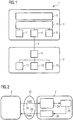
Figure 1 shows an exemplary embodiment of acomputer system 1 according to the present invention. Thecomputer system 1 comprises aclient device 2 such as a mini PC or a thin client device, and adisplay device 3 such as a flat screen LCD display device. Theclient device 2 and thedisplay device 3 are connected by means of adata connection 4. For example, theclient device 2 and thedisplay device 3 may be connected by means of a full featured USB Type-C cable, comprising a plurality of wires for enabling USB data and control paths, transferring video data using a display port connection and for providing power from thedisplay device 3 to theclient device 2 by means of a power delivery standard. Thedata connection 4 is attached to theclient device 2 by means of afirst interface 5 and to thedisplay device 3 by means of asecond interface 6. In the described embodiment, theclient device 2 is connected to thedisplay device 3 using only a single cable, which is used to supply theclient device 2 with an operating energy provided by the display device. - The
display device 3 comprises a power button 7, a status LED 8, adisplay screen 9 andcontrol circuitry 10. Theclient device 2 comprises aprocessor 11 for executing user programs as well as an operating system and firmware components, agraphics component 12 for generating graphical output to be displayed by thedisplay screen 9 and apower management subsystem 13 to control the operating state of theclient device 2. Thegraphics component 12 and thepower management subsystem 13 may be implemented in hardware or in software or a combination thereof. For example, thepower management subsystem 13 may comprise parts of a system firmware for ACPI control, such as a BIOS, parts of an operating system and hardware components used to activate or deactivate individual components or subcomponents of theclient device 2. - In an advantageous embodiment, in operation of the
computer system 1, power control commands received by thedisplay device 3 via the power button 7 may be forwarded by thecontrol circuitry 10 via thedata connection 4 to thepower management subsystem 13 of theclient device 2. Inversely, the power state of theclient device 2 may be communicated via thedata connection 4 to thecontrol circuitry 10 of thedisplay device 3 and indicated using the status LED 8. In this way, a so called "all-in-one mode" of thedisplay device 3 in combination with aclient computing device 2 may be implemented. -
Figure 2 shows a block diagram of internal components of adisplay device 3 connected to aclient device 2 according to an embodiment of the present invention. Specifically,Figure 2 shows a schematic diagram of the control paths within thedisplay device 3 and data and control paths between theclient device 2 and thedisplay device 3. The block diagram ofFigure 2 shows, in particular, those parts of a chip set of adisplay device 3 that are responsible for power delivery to theclient device 2. - In the described embodiment, the
client device 2, acting as a source for a display signal, and thedisplay device 3, acting as a sink for the display signal, are connected by aUSB interface 21, for example a USB Type-C data cable. TheUSB interface 21 comprises acontrol path 22 for exchanging control and configuration signals between theclient device 2 and thedisplay device 3, and apower delivery path 23 for supplying an operating power from thedisplay device 3 to theclient device 2. On the side of thedisplay device 3, thecontrol path 22 ends at apower delivery controller 24. - The
display device 3 further comprises ascaler 25 for scaling a display signal provided by theclient device 2 and a display screen (not shown inFigure 2 ) for displaying the display signal to a user of theclient device 2. Thescaler 25 represents the main processing unit inside thedisplay device 3. Thescaler 25 and thepower delivery controller 24 are connected by a control interface, for example an I2C bus. - In operation, the
scaler 25 will receive an internal control signal from thepower delivery controller 24 based on control and configuration data of theclient device 2 received by thepower delivery controller 24. In particular, thepower delivery controller 24 may signal whether a device requiring uninterrupted power delivery has been connected to the display device. - The
display device 3 further comprise apower circuit 26 connected to thescaler 25. In operation, thescaler 25 can instruct thepower circuit 26 to start or stop a power delivery to theclient device 2. According to the described embodiment, this decision is made based on the information received from thepower delivery controller 24 during an initial handshake procedure and the operating state of the monitor determined by thescaler 25 itself. Thepower delivery controller 24 and thepower circuit 26 may be integrated into an internal USB hub or another power delivery circuit of the display device (not shown). - The invention will be described in more detail using the operating states S1 to S10 and external events E1 to E3 of the state diagram shown in
Figure 3 . - When a
display device 3 is connected to an operating power (event E1), thedisplay device 3 first enters a "start state" (state S1). For example, a LCD monitor with an internal power supply unit can be plugged into a mains socket using an AC mains cable. Alternatively, an external power supply for the display device may be connected with a mains socket and the display device using corresponding AC and/or DC plug connectors. - After the supplied operating voltage has stabilized, the display device changes into a so-called "power-off state" (state S2). In the power-off state S2, the supply voltage provided to the monitor is provided at least to power management circuitry of the
display device 3, e.g. parts of thecontrol circuitry 10, to keep those parts necessary for activating thedisplay device 3 alive. However, many other components of thedisplay device 3, such as adisplay screen 9, will not be operational in state S2 of thedisplay device 3. - After the user presses a power button 7 to switch the
display device 3 on, thedisplay device 3 will first change into an "initial state" (state S3), in which internal control components of thedisplay device 3 are initialized. In particular, ascaler 25 will initialize scaler registers and panel parameters for thedisplay device 3. - Once this initialization is complete, the
display device 3 enters a "cable detection state" (state S4). In state S4, thedisplay device 3 determines whether it is connected to aclient device 2. In particular, the display device detects whether a USB Type-C cable is connected to a corresponding plug connecter of thedisplay device 3. Different types of connections can be detected. In particular, a USB connection to a compatible client device, e.g. a client device of a given manufacturer such as Fujitsu Technology or Fujitsu Limited, can be detected (event E2). Alternatively, a USB connection to an incompatible client device, e.g. a client device of another manufacturer, can be detected (event E3). The detection result is established and stored within a scaler register for later use as detailed below. - Once a connection is detected, the
display device 3 enters a "signal search state" (state S5). In the state S5, the monitor tries to find a valid signal and prepares thedisplay device 3 to output a found signal. In state S5, thedisplay device 3 may also identify which of a plurality of possible signal sources is connected to thedisplay device 3. - If an active video signal is provided by the
client device 2 via a detected connection, thedisplay device 3 will change into an "active state" (state S6) until the provision of the video signal is stopped or thedisplay device 3 is switched off. If no such active video signal is detected, thedisplay device 3 will change into a "no signal state" (state S7). - After a predetermined time interval in the state S7, the
display device 3 will change into a "sleep state" (state S8) in case anincompatible client device 2 was detected in state S4, wherein unused components of thedisplay device 3 are deactivated or switched into a low power consumption status. For example, a backlight unit of thedisplay screen 9 may be dimmed or switched off completely. Also, a display panel of thedisplay screen 9 may be deactivated in state S8. The status LED 8 may be powered to indicate the state S8. Moreover, thescaler 25 will be at least partially powered to detect the provision of an active signal from the client device at a later stage. - When the user switches the
display device 3 manually off the power button 7 in state S8, thedisplay device 3 will enter the state S2 again, and the status LED 8 will be switched off. Thedisplay device 3 may also change into the state S2, if anincompatible client device 2 was detected in state S4 and the power button 7 of the display device is pressed by the user thereafter. - Power management circuitry of conventional display devices tries to deactivate as many internal components as possible, at least during a switched-off mode and an energy-saving mode, in order to reduce a power consumption. As a consequence, external interfaces such as a USB interface provided by a conventional display device are deactivated. In the case that the display device is used to supply an operating energy to a client system, for example via a full-featured USB Type-C interface and/or a USB power delivery function, this may result in an unintended disruption of the operating power of the client system.
- In order to address the above-mentioned problem, in an embodiment of the present invention, the
control circuitry 10 of thedisplay device 3 implements two additional states as also indicated inFigure 3 . - In the described embodiment, the
client device 2 and thedisplay device 3 are connected via a so-called fully featured USB Type-C connection. Theclient device 2 and thedisplay device 3 implement the so-called Power Delivery Specification according to the USB Specification 3.1. According to this standard, in a handshake procedure performed in state S4, theclient device 2 may request an appropriate amount of power to be delivered by thedisplay device 3. For example, theclient device 2 could request a supply voltage of 20 V and a supply current of 3 A, corresponding to an operating power of 60 W for theclient device 2. - As part of this handshake procedure, the
client device 2 may also transmit one or multiple vendor-defined messages (VDM) as defined in the Power Delivery Specification 2.0 or 3.0. Such messages can be defined by individual vendors and be used to communicate information outside the scope of predefined parameters of the respective standard. - The parameters exchanged between the
client device 2 and thedisplay device 3 are shown in the handshaking flow chart ofFigure 4 . In the particular embodiment described, theclient device 2 discovers a list of standard or vendor identifier (SVID) supported by thedisplay device 3. Based on the so-called USB Type-C AltMode Standard, only the client device can ask for the SVID from the display device. The first four steps shown inFigure 4 are following a standard request. - In order to establish whether the
display device 3 supports the so-called all-in-one mode, according to the described embodiment of the present invention, instep 41, theclient device 2 additionally requests to discover modes with a predetermined SVID, corresponding to Fujitsu devices. If the display device supports the so-called "all-in-one mode", this request is acknowledged in thestep 42. Subsequently, theclient device 2 requests to enter this mode instep 43, which is again acknowledged in acorresponding step 44. Together, thesteps 41 to 44 implement the all-in-one mode detection and selection. - In the described embodiment,
only client devices 2 of a given vendor, for example Fujitsu Technology Solutions GmbH or Fujitsu Ltd., will be supported to implement seamless power delivery. That is to say, in case thedisplay device 3 receives a predefined SVID from theclient device 2, this information may be sufficient to identify that theclient device 2 shall be provided with an operating energy even in the case that thedisplay device 3 enters an energy-saving state. However, in a variation of the described embodiment, only certain types of a given vendor are supported by thedisplay device 3. For example, only thin client devices of that vendor may be supported for seamless power delivery. In this situation, only a valid combination of a SVID and a PID provided by theclient device 2 will be compared with a corresponding list of supported devices by thedisplay device 3. Of course, a PID alone may also be used for detection. - If a successful match is found, that is to say if event E2 is detected in the state S4, a corresponding flag or scaler register is set within the
display device 3 for future state changes. - In case a
compatible client device 2 is successfully detected in the state S4, but no active video signal is provided in the state S5 by the detectedclient device 2, thedisplay device 3 will enter a "light sleep state" (state S9). The light sleep state S9 essentially corresponds to the sleep state S8 with the exception that thedisplay device 3 will keep providing a supply power to the attachedclient device 2. Together, the two sleep states S8 and S9 provide an enhanced energy saving mode for thedisplay device 3. - Moreover, in case the power button 7 of the
display device 3 is pressed while thedisplay device 3 is in one of the states S4 to S7 or S9, and acompatible client device 2 has been detected in state S4, thedisplay device 3 will change into an "idle state" (state S10) instead of the power-off state S2. The idle state S10 corresponds essentially to the power-off state S2, except that thedisplay device 3 will keep providing a supply power via theinterface 6 to thedisplay device 3. Together, the power-off state S2 and the idle state S10 provide an enhanced switched-off mode for thedisplay device 3. - In the table below, the various states and events of the state diagram according to
Figure 3 are briefly summarized.State Description S1 Start State Monitor with AC power-in. S2 Power-off State Monitor with AC power to keep the electrical part alive, but not in working status due to power off by DC power key. S3 Initial State Initialized the scaler registers and panel parameters. S4 Cable detection State Detecting if there is a USB-C cable inserted into monitor S5 Signal Search State Monitor tries to find out the valid signal and prepare the signal output. If there is no valid signal found, then it will go for the next proper state instead. S6 Active State Monitor in normal working status. S7 No Signal State No active signal source is alive. S8 Sleep State Monitor in low power consumption status with turning off LCD panel and other unused electronic components. Only LED indicator and scaler is still alive to detect the active signal. S9 Light sleep State Monitor in low power consumption status same as Sleep State, but also keep the USB block alive when connected with FTS devices by USB Type-C cable. S10 Idle State Same as power-off status but still keep USB block alive when connected with FTS devices by USB Type-C cable. External Event Description E1 Power plug-in Plug the power cord to monitor side. E2 USB-C cable plug/unplug with FTS device Connecting compatible Fujitsu source devices, such as PC or notebook to monitor with USB Type-C cable E3 USB-C cable plug/unplug with Non-FTS device Connecting incompatible Non-Fujitsu source devices, such as PC or notebook to monitor with USB Type-C cable. - The operation of a
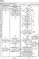
display device 3 according to an embodiment of the present invention is described in detail with respect to the flowchart ofFigure 5 . - In an
initial step 51, a USB cable is plugged into theclient device 2 and thedisplay device 3 to establish a USB Type-C connection. This action is detected by parts of a power delivery circuit, e.g. apower delivery controller 24, in astep 52, which therefore initializes a power delivery handshaking protocol. During the handshake procedure, a standard or vendor ID (SVID) of theclient device 2 is received by the power delivery circuit of thedisplay device 3. - Upon successful completion of the handshake procedure, the power delivery circuit will send an interrupt signal to a
scaler 25 to signal that this information has been received instep 53. Thus, in asubsequent step 54, thescaler 25 will compare the received SVID with a predefined pattern. In the example shown inFigure 5 , the SVID is compared with a fixed hexadecimal value of 0BF8 indicating adisplay devices 2 requesting a continuous power delivery. - If said SVID value is identified, in a
step 55, a register value of thescaler 25 will be set to indicate that acompatible client device 2 is connected to thedisplay device 3. Inversely, if the predefined value is not received from theclient device 2, in astep 56 the corresponding scaler register is reset to indicate that thedisplay system 3 is operating in a conventional operating mode, for example an operating mode as defined by the Energy Star Display Specifications Version 7. In either case, the method proceeds to step 57, wherein the monitor state is continuously checked by means of the state machine as detailed with regard toFigure 3 . - If, in a
step 58, it is established that the monitor is in the no signal state S7 or the power button 7 has been pressed, instep 59, thescaler 25 checks if the control register is set. If said register is set, instep 60 thescaler 25 instructs a power delivery part of the power delivery circuit, e.g. thepower circuit 26, to keep the power supply for theclient device 2 activated based on a power delivery controller feedback received during the initial handshake. Accordingly, instep 61, theclient device 2 is kept alive, i.e. is supplied with the previously requested supply power. Moreover, instep 62, thescaler 25 goes to either the light sleep state S9 or to the idle state S10 based on the triggering event detected instep 58. - However, if it is established, in
step 59, that the corresponding scaler register was not set, thescaler 25 turns off the power supply to an internal USB hub and/or the power delivery part of the power delivery circuit instep 63. Accordingly, the power delivery circuit cuts off the power supply to theexternal client device 2 in astep 64. This leads to a controlled or uncontrolled shutdown of thedevice 2 instep 65. Moreover, instep 66, thescaler 25 of thedisplay device 3 will either change into the sleep state S8 or the power-off state S2 according to the triggering event detected instep 58. - If no such triggering event is detect in
step 58, instep 67 thedisplay device 3 will enter into or remain in the signal search state S5. - The above steps make sure that the power delivery function of the
display device 3 is kept working even when thedisplay device 3 itself enters an energy saving state, such as the internal, light sleep state S9 or a power-off/idle state S10, so that theexternal client device 2, especially a thin client PC, can be kept alive. This avoids the unexpected shutdown scenario for an end user of theclient device 2. - At the same time, by querying and analyzing whether the
client device 2 belongs to a predefined group of client devices, the method makes sure that thedisplay device 3 meets the Energy Star 7.0 criteria for other types of client devices. Thus, whether the power delivery circuit will be turned off or kept alive depends on the Energy Star pretest of the current embodiment, i.e. the result of the detection whether a Fujitsu Technology Solutions GmbH or Fujitsu Ltd. device has been detected by thedisplay device 3. -
- 1
- computer system
- 2
- client device
- 3
- display device
- 4
- data connection
- 5
- interface (of the client device)
- 6
- interface (of the display device)
- 7
- power button
- 8
- status LED
- 9
- display screen
- 10
- control circuitry
- 11
- processor
- 12
- graphics component
- 13
- power management subsystem
- 21
- USB interface
- 22
- control path
- 23
- power delivery path
- 24
- power delivery controller
- 25
- scaler
- 26
- power circuit
- S1 to S10
- states (of the display device)
- E1 to E3
- external events
- 41 to 44
- protocol steps
- 51 to 67
- method steps
Claims (11)
- A computer system (1), comprising:- a client device (2), wherein the client device (2) is a client computing device acting as a source for a display signal; and- a display device (3), operationally connected to the client device (2) and acting as a sink for the display signal;
wherein- the display device (3) is configured to provide the client device (2) with an operating energy; and- the display device (3) is further configured to determine a standard or vendor identifier, SVID, and/or a product identifier, PID, received from the client device (2), to detect a type of the client device (2) based on a comparison of the determined SVID and/or PID with a predefined pattern, and, in case the client device (2) is a non-mobile device not equipped with a battery, to provide the client device (2) with an operating energy even if the display device (3) enters an energy-saving mode or is switched off. - The computer system (1) according to claim 1, wherein the display device (3) is specifically configured to provide the client device (2) with the operating energy over a combined signal and power delivery cable.
- The computer system (1) according to claim 1 or 2, wherein the client device (2) and the display device (3) are coupled by means of a USB Type-C cable.
- The computer system (1) according to any one of claims 1 to 3, wherein the display device (3) is configured to receive the SVID and/or the PID comprised in at least one vendor defined message, VDM.
- The computer system (1) according to any one of the claims 1 to 4, wherein the display device (3) is specifically configured to determine the SVID and/or PID by performing a handshake procedure with the client device (2) according to a power delivery standard when the client device (2) is connected to the display device (3).
- A display device (3), in particular for use in the computer system (1) according to claim 1, comprising:- a display screen (9) for displaying graphical output comprised in a video signal provided by an external client device (2), wherein the external client device (2) is a client computing device;- an interface (6) for connecting the display device (3) to the external client device (2); and- power management circuitry connected to the interface (6);
wherein- the interface (6) is configured to receive a control signal comprising information about a type of the client device (2) and the information about the type of the client device (2) comprising a standard or vendor identifier, SVID, and/or a product identifier, PID; and- the power management circuitry is configured to determine whether the client device (2) is a non-mobile device not equipped with a battery based on a comparison of the SVID and/or PID with a predefined pattern and to selectively provide an operating energy to the client device (2) via the interface (6), wherein, in an energy-saving mode or switched off mode of the display device (3), the power management circuitry provides the operating energy to the client device (2) in case the client device (2) is a non-mobile device not equipped with a battery, and does not provide the operating energy to the client device (2) in case the client device (2) is not a non-mobile device not equipped with a battery. - The display device (3) according to claim 6, wherein the display device (3) is configured to enter the energy-saving mode if no video signal is received from the client device (2) by the interface (6).
- The display device (3) according to any one of claim 6 and 7, wherein the power management circuitry implements a state machine comprising a plurality of operating states of the display device (3), wherein the plurality of operating states comprises at least the following states: a sleep state (S8), wherein the power management circuitry is in an active state, the display screen (9) is in a switched off or reduced power state, a status LED (8) of the display device (3) is in an active state, and the interface (6) does not provide the operating energy to the client device (2); and a light sleep state (S9), wherein the power management circuitry is in the active state, the display screen (9) is in the switched off or reduced power state, the status LED (8) of the display device (3) is in the active state and the interface (6) provides the operating energy to the client device (2).
- The display device (3) according to claim 8, wherein the plurality of operating states further comprise at least the following states: a power-off state (S2), wherein the power management circuitry is in the active state, the display screen (9) is in the switched off state, the status LED (8) of the display device (3) is in a switched off state, and the interface (6) does not provide an operating energy to the client device (2); and an idle state (S10), wherein the power management circuitry is in the active state, the display screen (9) is in the switched off state, the status LED (8) of the display device (3) is in the switched off state, and the interface (6) provides an operating energy to the client device (2).
- The display device (3) according to any one of claims 6 to 9, wherein the power management circuitry comprises:- power delivery circuitry comprising a power delivery controller (24), configured to selectively provide the operating energy via the interface (6) to the client device (2) and to receive the control signal comprising information about the type of the client device (2) from the interface (6); and- a scaler (25), configured to receive the video signal comprising the graphical output of the client device (2) for the display screen (9) from the interface (6);
wherein- the power delivery controller (24) is further configured to perform a handshake procedure with the client device (2) to establish the type of the client device (2) connected to the interface (6) and to provide a control signal to the scaler (25) indicative of the type of the client device (2). - The display device (3) according to claim 10, wherein the scaler (25) is further configured to control the operating state of the display device (3) based at least on the control signal received from the power delivery controller (24) and the detection of an active video signal from the interface (6) .
Priority Applications (1)
| Application Number | Priority Date | Filing Date | Title |
|---|---|---|---|
| US16/171,602 US10860076B2 (en) | 2017-10-27 | 2018-10-26 | Computer system, client device and display device |
Applications Claiming Priority (1)
| Application Number | Priority Date | Filing Date | Title |
|---|---|---|---|
| DE102017125289 | 2017-10-27 |
Publications (2)
| Publication Number | Publication Date |
|---|---|
| EP3477426A1 EP3477426A1 (en) | 2019-05-01 |
| EP3477426B1 true EP3477426B1 (en) | 2020-12-16 |
Family
ID=61027501
Family Applications (1)
| Application Number | Title | Priority Date | Filing Date |
|---|---|---|---|
| EP18153267.2A Active EP3477426B1 (en) | 2017-10-27 | 2018-01-24 | Computer system, client device and display device |
Country Status (2)
| Country | Link |
|---|---|
| US (1) | US10860076B2 (en) |
| EP (1) | EP3477426B1 (en) |
Families Citing this family (2)
| Publication number | Priority date | Publication date | Assignee | Title |
|---|---|---|---|---|
| US20200133359A1 (en) * | 2018-10-26 | 2020-04-30 | Toshiba Tec Kabushiki Kaisha | Image forming apparatus |
| WO2021021141A1 (en) * | 2019-07-30 | 2021-02-04 | Hewlett-Packard Development Company, L.P. | Power synchronizations between host devices and display devices |
Citations (3)
| Publication number | Priority date | Publication date | Assignee | Title |
|---|---|---|---|---|
| US20100306565A1 (en) * | 2009-05-26 | 2010-12-02 | Kabushiki Kaisha Toshiba | Information processor and power supply method |
| US20150249356A1 (en) * | 2010-12-02 | 2015-09-03 | Samsung Electronics Co., Ltd. | Method for charging external device by which unnecessary power consumption is alleviated and displaying apparatus using thereof |
| WO2017184159A1 (en) * | 2016-04-22 | 2017-10-26 | Hewlett-Packard Development Company, L.P. | Display device power mode |
Family Cites Families (6)
| Publication number | Priority date | Publication date | Assignee | Title |
|---|---|---|---|---|
| US20030107566A1 (en) * | 2001-12-08 | 2003-06-12 | Samsung Electronics Co., Ltd. | Display apparatus and method of supplying power to USB device thereof |
| JP2010108423A (en) * | 2008-10-31 | 2010-05-13 | Toshiba Corp | Information processor |
| JP2014115687A (en) * | 2012-12-06 | 2014-06-26 | Canon Inc | Data processing apparatus, method for controlling data processing apparatus, and program |
| KR102485617B1 (en) * | 2015-07-16 | 2023-01-09 | 삼성전자주식회사 | Display apparutus and control method of the same |
| US10268627B2 (en) * | 2016-08-23 | 2019-04-23 | Dell Products L.P. | Automatically configuring a universal serial bus (USB) type-C port of a computing device |
| JP6915344B2 (en) * | 2017-03-28 | 2021-08-04 | ブラザー工業株式会社 | Image processing device |
-
2018
- 2018-01-24 EP EP18153267.2A patent/EP3477426B1/en active Active
- 2018-10-26 US US16/171,602 patent/US10860076B2/en active Active
Patent Citations (3)
| Publication number | Priority date | Publication date | Assignee | Title |
|---|---|---|---|---|
| US20100306565A1 (en) * | 2009-05-26 | 2010-12-02 | Kabushiki Kaisha Toshiba | Information processor and power supply method |
| US20150249356A1 (en) * | 2010-12-02 | 2015-09-03 | Samsung Electronics Co., Ltd. | Method for charging external device by which unnecessary power consumption is alleviated and displaying apparatus using thereof |
| WO2017184159A1 (en) * | 2016-04-22 | 2017-10-26 | Hewlett-Packard Development Company, L.P. | Display device power mode |
Also Published As
| Publication number | Publication date |
|---|---|
| US10860076B2 (en) | 2020-12-08 |
| EP3477426A1 (en) | 2019-05-01 |
| US20190129486A1 (en) | 2019-05-02 |
Similar Documents
| Publication | Publication Date | Title |
|---|---|---|
| US7489974B2 (en) | Information processing apparatus and method for controlling power supply of the apparatus | |
| US6274949B1 (en) | Back-up power accessory for a computer | |
| US10042801B2 (en) | System for detecting universal serial bus (USB) device and method thereof | |
| US7853815B2 (en) | Method and apparatus for controlling power supply in a computer system under low power consumption mode | |
| JP2010108423A (en) | Information processor | |
| US20040042138A1 (en) | Data transfer control device, electronic equipment, and power supply switching method | |
| TW201133227A (en) | Power management method and related power management system | |
| JP2004157604A (en) | Usb peripheral control method and device | |
| JP2001306495A (en) | Portable communication terminal | |
| KR101330212B1 (en) | Control device of electric power for monitor and computer system and the method thereof | |
| JP2006163403A (en) | System and method of controlling graphics controller | |
| JPH08272497A (en) | Keyboard device | |
| JP2002304238A (en) | Data interface-controlled multiple plugs | |
| JP2009537890A (en) | Power supply control device and method for USB device | |
| TW201432432A (en) | Power management circuit and method thereof and computer system | |
| EP3477426B1 (en) | Computer system, client device and display device | |
| JP2000122756A (en) | Electronic equipment | |
| JP2004070785A (en) | Serial bus connecting apparatus and driver software | |
| US20100058085A1 (en) | Power-Saving Device and Method | |
| US11061848B1 (en) | Information processing apparatus and control method | |
| JP6669969B2 (en) | Function expansion device, electronic circuit, electronic system, and power control program | |
| JP7149421B2 (en) | ELECTRONIC DEVICE AND CONTROL METHOD OF ELECTRONIC DEVICE | |
| JP2001344047A (en) | Electronic equipment and power supply control method for electronic equipment | |
| JP2000099215A (en) | Interface for pc card | |
| CN111400225B (en) | USB switching circuit |
Legal Events
| Date | Code | Title | Description |
|---|---|---|---|
| PUAI | Public reference made under article 153(3) epc to a published international application that has entered the european phase |
Free format text: ORIGINAL CODE: 0009012 |
|
| STAA | Information on the status of an ep patent application or granted ep patent |
Free format text: STATUS: REQUEST FOR EXAMINATION WAS MADE |
|
| STAA | Information on the status of an ep patent application or granted ep patent |
Free format text: STATUS: EXAMINATION IS IN PROGRESS |
|
| 17P | Request for examination filed |
Effective date: 20190111 |
|
| AK | Designated contracting states |
Kind code of ref document: A1 Designated state(s): AL AT BE BG CH CY CZ DE DK EE ES FI FR GB GR HR HU IE IS IT LI LT LU LV MC MK MT NL NO PL PT RO RS SE SI SK SM TR |
|
| AX | Request for extension of the european patent |
Extension state: BA ME |
|
| 17Q | First examination report despatched |
Effective date: 20190409 |
|
| RAP1 | Party data changed (applicant data changed or rights of an application transferred) |
Owner name: FUJITSU CLIENT COMPUTING LIMITED |
|
| RIC1 | Information provided on ipc code assigned before grant |
Ipc: G06F 1/3215 20190101ALI20200525BHEP Ipc: G06F 13/42 20060101ALI20200525BHEP Ipc: G06F 1/26 20060101AFI20200525BHEP |
|
| GRAP | Despatch of communication of intention to grant a patent |
Free format text: ORIGINAL CODE: EPIDOSNIGR1 |
|
| STAA | Information on the status of an ep patent application or granted ep patent |
Free format text: STATUS: GRANT OF PATENT IS INTENDED |
|
| INTG | Intention to grant announced |
Effective date: 20200715 |
|
| GRAS | Grant fee paid |
Free format text: ORIGINAL CODE: EPIDOSNIGR3 |
|
| GRAA | (expected) grant |
Free format text: ORIGINAL CODE: 0009210 |
|
| STAA | Information on the status of an ep patent application or granted ep patent |
Free format text: STATUS: THE PATENT HAS BEEN GRANTED |
|
| AK | Designated contracting states |
Kind code of ref document: B1 Designated state(s): AL AT BE BG CH CY CZ DE DK EE ES FI FR GB GR HR HU IE IS IT LI LT LU LV MC MK MT NL NO PL PT RO RS SE SI SK SM TR |
|
| REG | Reference to a national code |
Ref country code: GB Ref legal event code: FG4D |
|
| REG | Reference to a national code |
Ref country code: IE Ref legal event code: FG4D |
|
| REG | Reference to a national code |
Ref country code: DE Ref legal event code: R096 Ref document number: 602018010727 Country of ref document: DE |
|
| REG | Reference to a national code |
Ref country code: AT Ref legal event code: REF Ref document number: 1346180 Country of ref document: AT Kind code of ref document: T Effective date: 20210115 |
|
| PG25 | Lapsed in a contracting state [announced via postgrant information from national office to epo] |
Ref country code: GR Free format text: LAPSE BECAUSE OF FAILURE TO SUBMIT A TRANSLATION OF THE DESCRIPTION OR TO PAY THE FEE WITHIN THE PRESCRIBED TIME-LIMIT Effective date: 20210317 Ref country code: NO Free format text: LAPSE BECAUSE OF FAILURE TO SUBMIT A TRANSLATION OF THE DESCRIPTION OR TO PAY THE FEE WITHIN THE PRESCRIBED TIME-LIMIT Effective date: 20210316 Ref country code: RS Free format text: LAPSE BECAUSE OF FAILURE TO SUBMIT A TRANSLATION OF THE DESCRIPTION OR TO PAY THE FEE WITHIN THE PRESCRIBED TIME-LIMIT Effective date: 20201216 Ref country code: FI Free format text: LAPSE BECAUSE OF FAILURE TO SUBMIT A TRANSLATION OF THE DESCRIPTION OR TO PAY THE FEE WITHIN THE PRESCRIBED TIME-LIMIT Effective date: 20201216 |
|
| REG | Reference to a national code |
Ref country code: AT Ref legal event code: MK05 Ref document number: 1346180 Country of ref document: AT Kind code of ref document: T Effective date: 20201216 |
|
| REG | Reference to a national code |
Ref country code: NL Ref legal event code: MP Effective date: 20201216 |
|
| PG25 | Lapsed in a contracting state [announced via postgrant information from national office to epo] |
Ref country code: BG Free format text: LAPSE BECAUSE OF FAILURE TO SUBMIT A TRANSLATION OF THE DESCRIPTION OR TO PAY THE FEE WITHIN THE PRESCRIBED TIME-LIMIT Effective date: 20210316 Ref country code: LV Free format text: LAPSE BECAUSE OF FAILURE TO SUBMIT A TRANSLATION OF THE DESCRIPTION OR TO PAY THE FEE WITHIN THE PRESCRIBED TIME-LIMIT Effective date: 20201216 Ref country code: SE Free format text: LAPSE BECAUSE OF FAILURE TO SUBMIT A TRANSLATION OF THE DESCRIPTION OR TO PAY THE FEE WITHIN THE PRESCRIBED TIME-LIMIT Effective date: 20201216 |
|
| PG25 | Lapsed in a contracting state [announced via postgrant information from national office to epo] |
Ref country code: HR Free format text: LAPSE BECAUSE OF FAILURE TO SUBMIT A TRANSLATION OF THE DESCRIPTION OR TO PAY THE FEE WITHIN THE PRESCRIBED TIME-LIMIT Effective date: 20201216 Ref country code: NL Free format text: LAPSE BECAUSE OF FAILURE TO SUBMIT A TRANSLATION OF THE DESCRIPTION OR TO PAY THE FEE WITHIN THE PRESCRIBED TIME-LIMIT Effective date: 20201216 |
|
| REG | Reference to a national code |
Ref country code: LT Ref legal event code: MG9D |
|
| PG25 | Lapsed in a contracting state [announced via postgrant information from national office to epo] |
Ref country code: SM Free format text: LAPSE BECAUSE OF FAILURE TO SUBMIT A TRANSLATION OF THE DESCRIPTION OR TO PAY THE FEE WITHIN THE PRESCRIBED TIME-LIMIT Effective date: 20201216 Ref country code: CZ Free format text: LAPSE BECAUSE OF FAILURE TO SUBMIT A TRANSLATION OF THE DESCRIPTION OR TO PAY THE FEE WITHIN THE PRESCRIBED TIME-LIMIT Effective date: 20201216 Ref country code: EE Free format text: LAPSE BECAUSE OF FAILURE TO SUBMIT A TRANSLATION OF THE DESCRIPTION OR TO PAY THE FEE WITHIN THE PRESCRIBED TIME-LIMIT Effective date: 20201216 Ref country code: LT Free format text: LAPSE BECAUSE OF FAILURE TO SUBMIT A TRANSLATION OF THE DESCRIPTION OR TO PAY THE FEE WITHIN THE PRESCRIBED TIME-LIMIT Effective date: 20201216 Ref country code: PT Free format text: LAPSE BECAUSE OF FAILURE TO SUBMIT A TRANSLATION OF THE DESCRIPTION OR TO PAY THE FEE WITHIN THE PRESCRIBED TIME-LIMIT Effective date: 20210416 Ref country code: RO Free format text: LAPSE BECAUSE OF FAILURE TO SUBMIT A TRANSLATION OF THE DESCRIPTION OR TO PAY THE FEE WITHIN THE PRESCRIBED TIME-LIMIT Effective date: 20201216 Ref country code: SK Free format text: LAPSE BECAUSE OF FAILURE TO SUBMIT A TRANSLATION OF THE DESCRIPTION OR TO PAY THE FEE WITHIN THE PRESCRIBED TIME-LIMIT Effective date: 20201216 |
|
| PG25 | Lapsed in a contracting state [announced via postgrant information from national office to epo] |
Ref country code: AT Free format text: LAPSE BECAUSE OF FAILURE TO SUBMIT A TRANSLATION OF THE DESCRIPTION OR TO PAY THE FEE WITHIN THE PRESCRIBED TIME-LIMIT Effective date: 20201216 Ref country code: PL Free format text: LAPSE BECAUSE OF FAILURE TO SUBMIT A TRANSLATION OF THE DESCRIPTION OR TO PAY THE FEE WITHIN THE PRESCRIBED TIME-LIMIT Effective date: 20201216 |
|
| REG | Reference to a national code |
Ref country code: CH Ref legal event code: PL |
|
| REG | Reference to a national code |
Ref country code: DE Ref legal event code: R097 Ref document number: 602018010727 Country of ref document: DE |
|
| PG25 | Lapsed in a contracting state [announced via postgrant information from national office to epo] |
Ref country code: LU Free format text: LAPSE BECAUSE OF NON-PAYMENT OF DUE FEES Effective date: 20210124 Ref country code: MC Free format text: LAPSE BECAUSE OF FAILURE TO SUBMIT A TRANSLATION OF THE DESCRIPTION OR TO PAY THE FEE WITHIN THE PRESCRIBED TIME-LIMIT Effective date: 20201216 Ref country code: IS Free format text: LAPSE BECAUSE OF FAILURE TO SUBMIT A TRANSLATION OF THE DESCRIPTION OR TO PAY THE FEE WITHIN THE PRESCRIBED TIME-LIMIT Effective date: 20210416 |
|
| REG | Reference to a national code |
Ref country code: BE Ref legal event code: MM Effective date: 20210131 |
|
| PLBE | No opposition filed within time limit |
Free format text: ORIGINAL CODE: 0009261 |
|
| STAA | Information on the status of an ep patent application or granted ep patent |
Free format text: STATUS: NO OPPOSITION FILED WITHIN TIME LIMIT |
|
| PG25 | Lapsed in a contracting state [announced via postgrant information from national office to epo] |
Ref country code: IT Free format text: LAPSE BECAUSE OF FAILURE TO SUBMIT A TRANSLATION OF THE DESCRIPTION OR TO PAY THE FEE WITHIN THE PRESCRIBED TIME-LIMIT Effective date: 20201216 Ref country code: AL Free format text: LAPSE BECAUSE OF FAILURE TO SUBMIT A TRANSLATION OF THE DESCRIPTION OR TO PAY THE FEE WITHIN THE PRESCRIBED TIME-LIMIT Effective date: 20201216 |
|
| 26N | No opposition filed |
Effective date: 20210917 |
|
| PG25 | Lapsed in a contracting state [announced via postgrant information from national office to epo] |
Ref country code: LI Free format text: LAPSE BECAUSE OF NON-PAYMENT OF DUE FEES Effective date: 20210131 Ref country code: CH Free format text: LAPSE BECAUSE OF NON-PAYMENT OF DUE FEES Effective date: 20210131 Ref country code: DK Free format text: LAPSE BECAUSE OF FAILURE TO SUBMIT A TRANSLATION OF THE DESCRIPTION OR TO PAY THE FEE WITHIN THE PRESCRIBED TIME-LIMIT Effective date: 20201216 |
|
| PG25 | Lapsed in a contracting state [announced via postgrant information from national office to epo] |
Ref country code: IE Free format text: LAPSE BECAUSE OF NON-PAYMENT OF DUE FEES Effective date: 20210124 Ref country code: ES Free format text: LAPSE BECAUSE OF FAILURE TO SUBMIT A TRANSLATION OF THE DESCRIPTION OR TO PAY THE FEE WITHIN THE PRESCRIBED TIME-LIMIT Effective date: 20201216 |
|
| PG25 | Lapsed in a contracting state [announced via postgrant information from national office to epo] |
Ref country code: SI Free format text: LAPSE BECAUSE OF FAILURE TO SUBMIT A TRANSLATION OF THE DESCRIPTION OR TO PAY THE FEE WITHIN THE PRESCRIBED TIME-LIMIT Effective date: 20201216 |
|
| PG25 | Lapsed in a contracting state [announced via postgrant information from national office to epo] |
Ref country code: IS Free format text: LAPSE BECAUSE OF FAILURE TO SUBMIT A TRANSLATION OF THE DESCRIPTION OR TO PAY THE FEE WITHIN THE PRESCRIBED TIME-LIMIT Effective date: 20210416 |
|
| PG25 | Lapsed in a contracting state [announced via postgrant information from national office to epo] |
Ref country code: BE Free format text: LAPSE BECAUSE OF NON-PAYMENT OF DUE FEES Effective date: 20210131 |
|
| PGFP | Annual fee paid to national office [announced via postgrant information from national office to epo] |
Ref country code: FR Payment date: 20230123 Year of fee payment: 6 |
|
| PGFP | Annual fee paid to national office [announced via postgrant information from national office to epo] |
Ref country code: GB Payment date: 20230124 Year of fee payment: 6 Ref country code: DE Payment date: 20230124 Year of fee payment: 6 |
|
| PG25 | Lapsed in a contracting state [announced via postgrant information from national office to epo] |
Ref country code: CY Free format text: LAPSE BECAUSE OF FAILURE TO SUBMIT A TRANSLATION OF THE DESCRIPTION OR TO PAY THE FEE WITHIN THE PRESCRIBED TIME-LIMIT Effective date: 20201216 |
|
| PG25 | Lapsed in a contracting state [announced via postgrant information from national office to epo] |
Ref country code: HU Free format text: LAPSE BECAUSE OF FAILURE TO SUBMIT A TRANSLATION OF THE DESCRIPTION OR TO PAY THE FEE WITHIN THE PRESCRIBED TIME-LIMIT; INVALID AB INITIO Effective date: 20180124 |