EP2461024A2 - Système, dispositif et procédé d'évaluation de la puissance d'éoliennes - Google Patents
Système, dispositif et procédé d'évaluation de la puissance d'éoliennes Download PDFInfo
- Publication number
- EP2461024A2 EP2461024A2 EP11190871A EP11190871A EP2461024A2 EP 2461024 A2 EP2461024 A2 EP 2461024A2 EP 11190871 A EP11190871 A EP 11190871A EP 11190871 A EP11190871 A EP 11190871A EP 2461024 A2 EP2461024 A2 EP 2461024A2
- Authority
- EP
- European Patent Office
- Prior art keywords
- wind turbine
- power output
- transfer function
- processor
- calculate
- Prior art date
- Legal status (The legal status is an assumption and is not a legal conclusion. Google has not performed a legal analysis and makes no representation as to the accuracy of the status listed.)
- Granted
Links
Images


Classifications
-
- F—MECHANICAL ENGINEERING; LIGHTING; HEATING; WEAPONS; BLASTING
- F03—MACHINES OR ENGINES FOR LIQUIDS; WIND, SPRING, OR WEIGHT MOTORS; PRODUCING MECHANICAL POWER OR A REACTIVE PROPULSIVE THRUST, NOT OTHERWISE PROVIDED FOR
- F03D—WIND MOTORS
- F03D7/00—Controlling wind motors
- F03D7/02—Controlling wind motors the wind motors having rotation axis substantially parallel to the air flow entering the rotor
- F03D7/028—Controlling wind motors the wind motors having rotation axis substantially parallel to the air flow entering the rotor controlling wind motor output power
-
- F—MECHANICAL ENGINEERING; LIGHTING; HEATING; WEAPONS; BLASTING
- F03—MACHINES OR ENGINES FOR LIQUIDS; WIND, SPRING, OR WEIGHT MOTORS; PRODUCING MECHANICAL POWER OR A REACTIVE PROPULSIVE THRUST, NOT OTHERWISE PROVIDED FOR
- F03D—WIND MOTORS
- F03D7/00—Controlling wind motors
- F03D7/02—Controlling wind motors the wind motors having rotation axis substantially parallel to the air flow entering the rotor
- F03D7/04—Automatic control; Regulation
- F03D7/042—Automatic control; Regulation by means of an electrical or electronic controller
- F03D7/043—Automatic control; Regulation by means of an electrical or electronic controller characterised by the type of control logic
- F03D7/046—Automatic control; Regulation by means of an electrical or electronic controller characterised by the type of control logic with learning or adaptive control, e.g. self-tuning, fuzzy logic or neural network
-
- F—MECHANICAL ENGINEERING; LIGHTING; HEATING; WEAPONS; BLASTING
- F05—INDEXING SCHEMES RELATING TO ENGINES OR PUMPS IN VARIOUS SUBCLASSES OF CLASSES F01-F04
- F05B—INDEXING SCHEME RELATING TO WIND, SPRING, WEIGHT, INERTIA OR LIKE MOTORS, TO MACHINES OR ENGINES FOR LIQUIDS COVERED BY SUBCLASSES F03B, F03D AND F03G
- F05B2260/00—Function
- F05B2260/82—Forecasts
- F05B2260/821—Parameter estimation or prediction
-
- F—MECHANICAL ENGINEERING; LIGHTING; HEATING; WEAPONS; BLASTING
- F05—INDEXING SCHEMES RELATING TO ENGINES OR PUMPS IN VARIOUS SUBCLASSES OF CLASSES F01-F04
- F05B—INDEXING SCHEME RELATING TO WIND, SPRING, WEIGHT, INERTIA OR LIKE MOTORS, TO MACHINES OR ENGINES FOR LIQUIDS COVERED BY SUBCLASSES F03B, F03D AND F03G
- F05B2270/00—Control
- F05B2270/30—Control parameters, e.g. input parameters
- F05B2270/335—Output power or torque
-
- Y—GENERAL TAGGING OF NEW TECHNOLOGICAL DEVELOPMENTS; GENERAL TAGGING OF CROSS-SECTIONAL TECHNOLOGIES SPANNING OVER SEVERAL SECTIONS OF THE IPC; TECHNICAL SUBJECTS COVERED BY FORMER USPC CROSS-REFERENCE ART COLLECTIONS [XRACs] AND DIGESTS
- Y02—TECHNOLOGIES OR APPLICATIONS FOR MITIGATION OR ADAPTATION AGAINST CLIMATE CHANGE
- Y02E—REDUCTION OF GREENHOUSE GAS [GHG] EMISSIONS, RELATED TO ENERGY GENERATION, TRANSMISSION OR DISTRIBUTION
- Y02E10/00—Energy generation through renewable energy sources
- Y02E10/70—Wind energy
- Y02E10/72—Wind turbines with rotation axis in wind direction
Definitions
- the subject matter described herein relates generally to operating wind turbines and, more particularly, to determining a possible power output of one or more wind turbines when the wind turbines are operating in a curtailed state.
- Wind turbines utilize wind energy to generate or produce electrical power.
- Multiple wind turbines may be installed at a site to form a wind farm.
- the operator of a wind farm may operate wind turbines in the farm at a curtailed level of operation (i.e., less than a maximum level of operation).
- curtailed operation may be necessary to meet a maximum power output requested by the operator of a power grid to which the wind farm is connected.
- the wind farm operator may be entitled by a contractual, regulatory, or other obligation to compensation for revenue lost due to curtailment. Accordingly, the grid operator may wish to accurately estimate such lost revenue. Further, the wind farm operator may wish to determine an amount of excess capacity for power production when one or more wind turbines is operating in a curtailed state.
- a method for use in calculating a possible power output of a wind turbine includes acquiring a series of performance data samples. Each performance data sample includes a meteorological condition and a power output indicated at a first time by one or more sensors associated with a wind turbine. A transfer function is calculated by a computing system based at least in part on the series of performance data samples. The transfer function relates power output to the meteorological condition. A possible power output is calculated by the computer system based on the transfer function and at least one meteorological condition indicated by the one or more sensors at a second time.
- a device for use in calculating a possible power output of a wind turbine includes a sensor interface that is configured to receive an operating condition and a power output at a plurality of first times from one or more sensors associated with a wind turbine.
- the device also includes a memory device that is coupled in communication with the sensor interface and configured to store a series of performance data samples that include an operating condition and a power output.
- the device further includes a processor that is coupled in communication with the memory device and programmed to calculate a transfer function relating power output to the operating condition based at least in part on the series of performance data samples, and to calculate a possible power output based on the transfer function and an operating condition received by the sensor interface at a second time.
- one or more computer-readable storage media having computer-executable instructions embodied thereon When executed by at least one processor, the computer-executable instructions cause the processor to calculate a transfer function relating power output of a wind turbine to a meteorological condition based at least in part on a series of performance data samples. Each performance data sample includes a power output of the wind turbine and a meteorological condition of the wind turbine that are indicated while the wind turbine is operated in a non-curtailed state. The computer-executable instructions further cause the processor to calculate a possible power output of the wind turbine based at least in part on the transfer function and a meteorological condition of the wind turbine indicated while the wind turbine is operated in a curtailed state.
- Various of the embodiments described herein facilitate determining a difference between a possible or potential power output and an actual, measured power output for one or more wind turbines.
- Possible power output may be calculated using a transfer function that relates power output to one or more operating conditions.
- Operating conditions include, without limitation, meteorological conditions, mechanical conditions, and any other factors that may affect wind turbine power output.
- a meteorological condition may include, for example, a wind speed, a wind direction, an air temperature, an air density, a humidity level, and/or an air pressure.
- a transfer function is created from data sampled while a wind turbine is operating in a normal, non-curtailed state.
- the transfer function may be calculated repeatedly, such that the transfer function reflects changes in the relationship between power output and an operating condition over time.
- the same operating conditions used to create the transfer function may be used in combination with the transfer function to estimate a possible power production of a wind turbine operating in a curtailed state. Accordingly, embodiments described herein enable a possible power calculation to be applied when a wind turbine is curtailed, and further enable the accuracy of the possible power calculation to be evaluated and/or improved when the wind turbine is not curtailed. When the wind turbine is not curtailed, both predicted and measured power outputs may be available. Moreover, the methods described may be applied to a plurality of wind turbines within a wind farm.
- An exemplary technical effect of the methods, system, and apparatus described herein includes at least one of: (a) acquiring a series of performance data samples, wherein each performance data sample of the plurality of performance data samples includes an operating condition and a power output indicated at a first time by one or more sensors associated with a wind turbine; (b) calculating a transfer function based at least in part on the series of performance data samples, wherein the transfer function relates power output to the operating condition; and (c) calculating a possible power output based on the transfer function and at least one operating condition indicated by the one or more sensors at a second time.
- Fig. 1 is a perspective view of an exemplary wind turbine 100.
- Wind turbine 100 includes a nacelle 102 that houses a generator (not shown in Fig. 1 ). Nacelle 102 is mounted on a tower 104 (only a portion of tower 104 is shown in Fig. 1 ).
- Tower 104 may have any suitable height that facilitates operation of wind turbine 100 as described herein.
- wind turbine 100 also includes a rotor 106 that includes three rotor blades 108 coupled to a rotating hub 110.
- wind turbine 100 may include any number of rotor blades 108 that enable operation of wind turbine 100 as described herein.
- wind turbine 100 includes a gearbox (not shown) that is rotatingly coupled to rotor 106 and to the generator.
- wind turbine 100 includes one or more sensors 120 and/or control devices 135 (shown in Fig. 2 ). Sensors 120 sense or detect wind turbine operating conditions.
- sensor(s) 120 may include a wind speed and/or a direction sensor (e.g., an anemometer), an ambient air temperature sensor, an air density sensor, an atmospheric pressure sensor, a humidity sensor, a power output sensor, a blade pitch sensor, a turbine speed sensor, a gear ratio sensor, and/or any sensor suitable for use with wind turbine 100.
- a wind speed and/or a direction sensor e.g., an anemometer
- an ambient air temperature sensor e.g., an air temperature sensor
- an air density sensor e.g., an air density sensor
- an atmospheric pressure sensor e.g., a humidity sensor
- a power output sensor e.g., a blade pitch sensor
- turbine speed sensor e.g., a gear ratio sensor
- gear ratio sensor e.g., gear ratio sensor, and/or any sensor
- Each sensor 120 generates and transmits one or more signals corresponding to a detected operating condition.
- an anemometer transmits a signal indicating a wind speed and/or a wind direction.
- each sensor 120 may transmit a signal continuously, periodically, or only once, for example, though other signal timings are also contemplated.
- Control devices 135 are configured to control an operation of wind turbine 100 and may include, without limitation, a brake, a relay, a motor, a solenoid, and/or a servomechanism.
- a control device 135 may adjust a physical configuration of wind turbine 100, such as an angle or pitch of rotor blades 108 and/or an orientation of nacelle 102 or rotor 106 with respect to tower 104.
- Fig. 2 is a block diagram illustrating an exemplary wind turbine controller 200 for use with wind turbine 100.
- Wind turbine controller 200 includes a processor 205 for executing instructions and a memory device 210 configured to store data, such as computer-executable instructions and operating conditions.
- Wind turbine controller 200 also includes a communication interface 215.
- Communication interface 215 is configured to be coupled in signal communication with one or more remote devices, such as another wind turbine controller 200 and/or a computing device (shown in Fig. 3 ).
- wind turbine controller 200 includes one or more sensor interfaces 220.
- Sensor interface 220 is configured to be communicatively coupled to one or more sensors 120, such as a first sensor 125 and a second sensor 130, and may be configured to receive one or more signals from each sensor 120.
- Sensor interface 220 facilitates monitoring and/or operating wind turbine 100.
- wind turbine controller 200 may monitor operating conditions (e.g., wind speed, wind direction, rotor speed, and/or power output) of wind turbine 100 based on signals provided by sensors 120.
- Memory device 210 may be configured to store the operating conditions. For example, a history of operating conditions may be stored in memory device 210.
- wind turbine controller 200 also includes a control interface 225, which is configured to be communicatively coupled to one or more control devices 135, such as a first control device 140 and a second control device 145.
- wind turbine control interface 225 is configured to operate control device 135 including a brake to prevent rotor 106 (shown in Fig. 1 ) from rotating.
- wind turbine control interface 225 may operate a control device 135 including a blade pitch servomechanism to adjust one or more rotor blades 108 (shown in Fig. 1 ) to a desired and/or predetermined pitch.
- the brake and the blade pitch servomechanism may be operated by the same control device 135 or a first control device 135 and a second control device 135.
- wind turbine controller 200 is configured to operate control devices 135 to achieve a desired noise level and/or a desired power output.
- wind turbine 100 may be operated in a curtailed state by adjusting the blade pitch to reduce power output.
- Fig. 3 is a block diagram illustrating an exemplary computing device 300.
- Computing device 300 includes a processor 305 for executing instructions.
- executable instructions are stored in a memory device 310.
- Memory device 310 is any device allowing information, such as executable instructions and/or other data, to be stored and retrieved.
- computing device 300 includes at least one presentation device 315 for presenting information to user 320.
- Presentation device 315 is any component capable of conveying information to user 320.
- Presentation device 315 may include, without limitation, a display device (e.g., a liquid crystal display (LCD), organic light emitting diode (OLED) display, or "electronic ink” display) and/or an audio output device (e.g., a speaker or headphones).
- presentation device 315 includes an output adapter, such as a video adapter and/or an audio adapter.
- An output adapter is operatively coupled to processor 305 and configured to be operatively coupled to an output device, such as a display device or an audio output device.
- presentation device 315 is configured to present wind turbine information, such as the possible and/or actual power output of one or more wind turbines 100 (shown in Fig. 1 ) to user 320.
- computing device 300 includes an input device 325 for receiving input from user 320.
- Input device 325 may include, for example, a keyboard, a pointing device, a mouse, a stylus, a touch sensitive panel (e.g., a touch pad or a touch screen), a gyroscope, an accelerometer, a position detector, and/or an audio input device.
- a single component, such as a touch screen, may function as both an output device of presentation device 315 and input device 325.
- Computing device 300 also includes a communication interface 330, which is configured to be communicatively coupled to one or more wind turbine controllers 200 and/or one or more other computing devices 300.
- Memory device 310 Stored in memory device 310 are, for example, computer-readable instructions for calculating a transfer function relating power output to one or more operating conditions, calculating a possible power output, providing a user interface to user 320 via presentation device 315, and/or receiving and processing input from input device 325.
- memory device 310 may be configured to store operating conditions, power output measurements, a transfer function, and/or any other data suitable for use with the methods described herein.
- Fig. 4 is a block diagram illustrating an exemplary computing system 400 for use in determining a possible power output of one or more wind turbines 100.
- System 400 includes a network 405.
- network 405 may include, without limitation, the Internet, a local area network (LAN), a wide area network (WAN), a wireless LAN (WLAN), a mesh network, and/or a virtual private network (VPN).
- LAN local area network
- WAN wide area network
- WLAN wireless LAN
- mesh network a mesh network
- VPN virtual private network
- a wind turbine site 410 includes a plurality of wind turbines 100, each of which includes a wind turbine controller 200.
- One or more computing devices 300 (shown in Fig. 3 ), such as a site monitor 415, are configured to be coupled in signal communication with wind turbine controllers 200 via network 405.
- site monitor 415 is positioned at wind turbine site 410.
- site monitor 415 may be positioned outside wind turbine site 410.
- site monitor 415 may be communicatively coupled to and may interact with wind turbine controllers 200 at a plurality of wind turbine sites 410.
- Each of site monitor 415 and wind turbine controller 200 includes a processor, as shown in Figs. 2 and 3 .
- a processor may include a processing unit, such as, without limitation, an integrated circuit (IC), an application specific integrated circuit (ASIC), a microcomputer, a programmable logic controller (PLC), and/or any other programmable circuit.
- a processor may include multiple processing units (e.g., in a multi-core configuration).
- Each of site monitor 415 and wind turbine controller 200 is configurable to perform the operations described herein by programming the corresponding processor.
- a processor may be programmed by encoding an operation as one or more executable instructions and providing the executable instructions to the processor in a memory device (also shown in Figs. 2 and 3 ) that is coupled to the processor.
- a memory device may include, without limitation, one or more random access memory (RAM) devices, one or more storage devices, and/or one or more computer-readable media.
- RAM random access memory
- one or more operating condition sensors 420 are coupled in communication with site monitor 415 and/or wind turbine controllers 200 (e.g., via network 405).
- Operating condition sensors 420 are configured to indicate an operating condition, such as a meteorological condition at a corresponding geographic position.
- operating condition sensors 420 may be configured to indicate a wind speed and/or a wind direction.
- An operating condition sensor 420 may be positioned apart from wind turbines 100 to facilitate reducing interference from wind turbines 100 with the operating condition indicated by operating condition sensor 420.
- wind turbines 100 may affect airflow, and therefore wind speed, within the vicinity of wind turbines 100.
- it may be assumed that interference by wind turbines 100 with measured operating conditions is relatively consistent, such that methods described herein are not adversely affected by such interference.
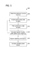
- Fig. 5 is a flowchart of an exemplary method 500 for use in calculating a possible power output of a wind turbine.
- Fig. 6 is a graph 600 illustrating power output of a wind turbine relative to wind speed.
- a reference transfer function is determined 505 for a wind turbine 100.
- the reference transfer function may be determined 505 experimentally based on one or more wind turbines 100 that are similar to the first wind turbine.
- wind turbines 100 may be considered similar based on having the same model designation and/or similar or identical components.
- the reference transfer function represents an expected relationship between an operating condition (e.g., a meteorological condition, such as wind speed) and power output of wind turbine 100.
- a reference power curve 605 illustrates an expected relationship between wind speed and power output.
- method 500 facilitates creating an adaptive transfer function with parameters that are estimated from observed data.
- wind turbine controller 200 acquires 510 a series of performance data samples.
- Each performance data sample includes an operating condition (e.g., a measured wind speed, in meters/second) and a power output (e.g., in kilowatts).
- the operating condition and the power output are associated with a time at which the values were indicated by a sensor 120.
- Performance data samples are represented by data points 610 in graph 600.
- wind turbine controller 200 filters 515 performance data samples. For example, wind turbine controller 200 may identify statistical outliers, such as operating condition values that are more than a predetermined number of standard deviations (e.g., 3 or 5) from a mean value and/or may identify unreasonable values outside a predetermined range (e.g., a wind speed below 0 meters/second or above 20 meters/second). Such statistical outliers and unreasonable values may be filtered 515 from the acquired performance data samples and disregarded.
- a predetermined number of standard deviations e.g., 3 or 5 5
- Wind turbine controller 200 calculates 520 a transfer function based at least in part on the performance data samples.
- the transfer function represents a model of wind turbine performance and relates power output to the operating condition(s) included in the performance data samples.
- v i and p i are wind speed and power output measurements, respectively, at time instance i .
- the reference transfer function is applied to the wind speeds to obtain an intermediate prediction of power output k i , as shown in Equation 1.
- k i f v i
- Equation 1 f () represents the reference transfer function determined 505 by wind turbine controller 200.
- the power output may be estimated by a linear regression model using Equation 2.
- Equation 2 p ⁇ i is an estimated (or predicted) value of p i , a i and b i are regression parameter values, at the end of time instance i , estimated from the data.
- the modified power curve model may represent the reference transfer function with a turbine-specific linear correction to the generic estimate.
- the parameters may be estimated by an online update equation, as described below.
- ⁇ 1 , ⁇ 2 , ... v i ..., ⁇ n and p 1 , p 2 , ... p i ..., p n represent the wind speed and power output measurements at time instances 1, 2, ... i ..., and n, respectively.
- the wind speeds are translated to generic power output estimates k 1 , k 2 , ... k i ..., k n using the reference transfer function, as shown in Equation 1.
- the parameter values a n and b n may be estimated using a least squares solution, as shown in Equations 3 and 4.
- Equation 3 may be expanded as shown in Equations 5 and 6.
- Equations 5 and 6 are averages of estimated power output and actual power output, respectively, at the end of n time instances.
- such average values may be calculated using Equations 7 and 8.
- Equations 5 and 6 may be expressed as Equations 9 and 10, which include terms defined by Equations 11 and 12.
- SSx ⁇ y n 1 n ⁇ U n - k ⁇ n ⁇ p ⁇ n
- SSx ⁇ x n 1 n ⁇ V n - k ⁇ n 2
- wind turbine controller 200 calculates updated values SSxy n +1 and SSxx n +1 .
- Equations 13-15 are a derivation of an exemplary function for determining SSxy n +1 .
- wind turbine controller 200 can compute the updated value of SSxy n +1 .
- the parameters U n , k ⁇ n , p ⁇ n , and n may be referred to as auxiliary parameters.
- Equation 16 is an exemplary function for determining SSxx n +1 .
- SSx ⁇ x n + 1 1 n + 1 ⁇ V n + k n + 1 2 - n ⁇ k ⁇ n + k n + 1 n + 1 2
- wind turbine controller 200 executes Equations 3 and 4 to calculate updated model parameters a n +1 and b n +1 .
- the average indicated power output p ⁇ n may be updated with a new value p n +1 as shown in Equation 17.
- Some embodiments facilitate weighted averaging of p ⁇ n .
- the effect of performance data samples may be weighted based on age. Equation 18 is an exemplary function for applying age-based weighting to p ⁇ n .
- p ⁇ n + 1 1 - ⁇ ⁇ p ⁇ n + ⁇ ⁇ p n + 1
- Equation 18 ⁇ is a constant, chosen from the range of zero to one, that represents a "forgetting factor", and causes older indicated values to have progressively less and less influence on the model parameters.
- weighting may be incorporated into any functions that include average values (e.g., Equations 15 and 16, which include U n and V n ). Applying age-based weighting enables the transfer function calculated 520 by wind turbine controller 200 to "track" changes in the relationship between power output and wind speed by giving higher weight to more recent observations.
- ⁇ is selected to cause the model to quickly adapt to the observed power curve.
- Very low values of ⁇ may restrict how quickly the model adapts to changes in the relationship between an operating condition and power output.
- ⁇ is selected based on how quickly such changes are expected to occur at site 410.
- a fitted power curve 615 represents the calculated power transfer function. As shown in Fig. 6 , fitted power curve 615 tracks data points 610 more closely than reference power curve 605 does. Further, the calculations described above require wind turbine controllers 200 to store calculated values, as opposed to a large collection of raw data. Accordingly, an accurate, wind turbine-specific transfer function may be provided without imposing significant data storage requirements on wind turbine controllers 200.
- wind turbine controller 200 calculates 520 the transfer function based on performance data samples acquired 510 at times when wind turbine 100 is operated in a normal, non-curtailed state. As such, the calculated transfer function represents the relationship between a maximum power output of wind turbine 100 and an operating condition.
- wind turbine controller 200 acquires 525 one or more operating conditions that correspond to the operating conditions used to calculate 510 the transfer function.
- acquiring 525 an operating condition includes acquiring 525 a plurality of samples of the operating condition and calculating an average of the sampled values The operating condition samples may be filtered, as described above with respect to filtering 515 performance data samples.
- Wind turbine controller 200 calculates 530 a possible power output for the time corresponding to the operating condition(s) acquired 525 by wind turbine controller 200 based on the transfer function and the acquired operating condition(s).
- the possible power output represents an estimated power output that would have been produced by wind turbine 100 at the time corresponding to the operating condition(s) if wind turbine 100 had been operated in a non-curtailed state.
- a wind force may be calculated at least in part by multiplying wind speed by air density.
- Fig. 7 is a flowchart of an exemplary method 700 for determining a difference between actual power output and possible power output of wind turbine site 410. Referring to Figs. 4 and 7 , in an exemplary embodiment, method 700 is performed by site monitor 415 and/or wind turbine controllers 200.
- each wind turbine controller 200 may calculate 500 (shown in Fig. 5 ) a possible power output of a corresponding wind turbine 100 and transmit the possible power output of wind turbine 100 to site monitor 415.
- site monitor 415 may receive performance data samples and/or operating conditions from one or more wind turbine controllers 200 and calculate 500 the possible power output.
- the possible power output of each wind turbine 100 is added 710 to a total possible power output, and a total indicated power output for wind turbines 100 is determined 715.
- site monitor 415 may receive an indicated power output from each wind turbine controller 200 and add the received power outputs to calculate a total indicated power output.
- site monitor 415 may receive an indication of a total power output from a sensor 420.
- the total power output may be indicated at a point where wind turbines 100 are coupled to a transmission line and/or an electrical grid (not shown).
- Site monitor 415 calculates 720 the difference between the total possible power output and the total indicated power output. In one embodiment, site monitor 415 calculates 720 the difference between the total possible power output and the total indicated power output for a duration in which wind turbines 100 are operated in a curtailed state.
- the difference calculated 720 by site monitor 415 represents an excess power output capacity of site 410.
- the excess capacity may be used to determine compensation that is due to the site operator as a result of curtailing operation of wind turbines 100.
- Embodiments provided herein facilitate efficiently updating a transfer function relating power output of a wind turbine to one or more operating conditions as new measurement data becomes available, without requiring all historical measurements to be stored. Accordingly, the accuracy of possible power output estimations for the wind turbine may be increased. Further, the methods provided herein may be practiced with respect to a plurality of wind turbines in a wind turbine site to determine a total possible power output of the site.
- the transfer function parameters may be updated using recursive least squares, neural networks, and/or adaptive filter techniques.
- the methods described herein may be encoded as executable instructions embodied in a computer-readable medium including, without limitation, a memory device of a computing device. Such instructions, when executed by a processor, cause the processor to perform at least a portion of the methods described herein.
- Exemplary embodiments of a wind turbine control system are described above in detail.
- the system, devices, wind turbine, and included assemblies are not limited to the specific embodiments described herein, but rather each component may be utilized independently and separately from other components described herein.
Landscapes
- Engineering & Computer Science (AREA)
- Mechanical Engineering (AREA)
- Sustainable Development (AREA)
- Sustainable Energy (AREA)
- Chemical & Material Sciences (AREA)
- Combustion & Propulsion (AREA)
- Life Sciences & Earth Sciences (AREA)
- General Engineering & Computer Science (AREA)
- Physics & Mathematics (AREA)
- Artificial Intelligence (AREA)
- Evolutionary Computation (AREA)
- Fuzzy Systems (AREA)
- Mathematical Physics (AREA)
- Software Systems (AREA)
- Wind Motors (AREA)
Applications Claiming Priority (1)
| Application Number | Priority Date | Filing Date | Title |
|---|---|---|---|
| US12/961,269 US8150641B2 (en) | 2010-12-06 | 2010-12-06 | System, device, and method for estimating possible power output of wind turbines |
Publications (3)
| Publication Number | Publication Date |
|---|---|
| EP2461024A2 true EP2461024A2 (fr) | 2012-06-06 |
| EP2461024A3 EP2461024A3 (fr) | 2017-10-18 |
| EP2461024B1 EP2461024B1 (fr) | 2019-08-14 |
Family
ID=44560759
Family Applications (1)
| Application Number | Title | Priority Date | Filing Date |
|---|---|---|---|
| EP11190871.1A Active EP2461024B1 (fr) | 2010-12-06 | 2011-11-28 | Système, dispositif et procédé d'évaluation de la puissance d'éoliennes |
Country Status (4)
| Country | Link |
|---|---|
| US (1) | US8150641B2 (fr) |
| EP (1) | EP2461024B1 (fr) |
| CN (1) | CN102562459B (fr) |
| DK (1) | DK2461024T3 (fr) |
Cited By (2)
| Publication number | Priority date | Publication date | Assignee | Title |
|---|---|---|---|---|
| EP2673501A4 (fr) * | 2011-02-11 | 2016-04-13 | Xzeres Corp | Système et procédé pour commander une turbine éolienne, comprenant la commande de paramètres de lacet ou autres |
| WO2024223014A1 (fr) * | 2023-04-28 | 2024-10-31 | Vestas Wind Systems A/S | Vérification des performances d'une éolienne |
Families Citing this family (38)
| Publication number | Priority date | Publication date | Assignee | Title |
|---|---|---|---|---|
| WO2009156299A2 (fr) * | 2008-06-26 | 2009-12-30 | Alstom Technology Ltd | Procédé d'estimation de la capacité de production d'énergie maximum et de gestion d'une réserve d'énergie spécifiée pour centrale énergétique à turbine à gaz à cycle simple ou combinée et système de production d'énergie s'utilisant avec ce procédé |
| JP4995209B2 (ja) * | 2009-01-05 | 2012-08-08 | 三菱重工業株式会社 | 風力発電装置及び風力発電装置の風向推定方法 |
| DK177434B1 (en) * | 2010-06-18 | 2013-05-21 | Vestas Wind Sys As | Method for controlling a wind turbine |
| US8489247B1 (en) * | 2011-03-18 | 2013-07-16 | Rockwell Collins, Inc. | Agent-based chaotic control of wind turbines |
| US9002483B1 (en) | 2011-03-18 | 2015-04-07 | Rockwell Collins, Inc. | Diploid control of water heaters |
| US8849737B1 (en) | 2011-03-18 | 2014-09-30 | Rockwell Collins, Inc. | Prediction method of predicting a future state of a system |
| US8606418B1 (en) | 2011-03-18 | 2013-12-10 | Rockwell Collins, Inc. | Wind prediction for wind farms through the use of weather radar |
| US20120271593A1 (en) * | 2011-04-21 | 2012-10-25 | Honeywell International Inc. | Monitoring wind turbine performance |
| US8249852B2 (en) * | 2011-05-19 | 2012-08-21 | General Electric Company | Condition monitoring of windturbines |
| CA2840199C (fr) * | 2011-06-23 | 2019-05-14 | Inventus Holdings, Llc | Generation electrique a multiples sites renouvelables et commande de puissance reactive |
| CN104380215A (zh) * | 2012-04-16 | 2015-02-25 | Kk风能解决方案公司 | 数据采集系统以及从风力涡轮机采集数据的方法 |
| EP2920459B1 (fr) * | 2012-08-15 | 2018-11-21 | Vestas Wind Systems A/S | Système de commande de centrale éolienne, centrale éolienne comprenant un système de commande de centrale éolienne et procédé de commande de centrale éolienne |
| CA2829247C (fr) | 2012-10-12 | 2017-03-14 | General Electric Company | Systeme et procede de repartition de l'energie eolienne dans un parc eolien |
| CN103001249B (zh) * | 2012-11-15 | 2016-01-20 | 中国电力科学研究院 | 基于bp神经网络的风电场短期功率预测方法 |
| CN104021424B (zh) | 2013-02-28 | 2018-12-07 | 乌托巴斯洞察公司 | 用于预测风场中的风机的输出功率的方法和装置 |
| DE102013205838A1 (de) * | 2013-04-03 | 2014-10-09 | Senvion Se | Effizienzüberwachungsverfahren eines Windenergieanlagenparks |
| US9690884B2 (en) * | 2013-06-05 | 2017-06-27 | WindLogics Inc. | Wind farm prediction of potential and actual power generation |
| US20150077155A1 (en) * | 2013-09-18 | 2015-03-19 | Palle Clausen | Monitoring of wind turbine performance |
| US20150278405A1 (en) | 2014-03-31 | 2015-10-01 | Vestas Wind Systems A/S | Method for evaluating a performance prediction for a wind farm |
| CN106922162B (zh) * | 2014-09-29 | 2019-04-23 | 维斯塔斯风力系统有限公司 | 验证传感器的方法、风场、控制器以及控制机舱偏航系统的方法 |
| US10712717B2 (en) | 2015-05-15 | 2020-07-14 | General Electric Company | Condition-based validation of performance updates |
| EP3380724B1 (fr) | 2015-11-26 | 2020-01-08 | Vestas Wind Systems A/S | Procédé de surveillance et d'évaluation des changements de performances énergétiques d'une éolienne |
| US10794366B2 (en) | 2015-11-26 | 2020-10-06 | Vestas Wind Systems A/S | Method for monitoring and assessing power performance changes of a wind turbine |
| WO2017108044A1 (fr) * | 2015-12-23 | 2017-06-29 | Vestas Wind Systems A/S | Commande de turbines éoliennes en fonction d'estimations de fiabilité |
| FR3053121B1 (fr) * | 2016-06-27 | 2018-07-27 | Electricite De France | Procede d'estimation de l'energie ecretee par une source de production electrique intermittente |
| US10539116B2 (en) | 2016-07-13 | 2020-01-21 | General Electric Company | Systems and methods to correct induction for LIDAR-assisted wind turbine control |
| WO2018224103A1 (fr) | 2017-06-07 | 2018-12-13 | Vestas Wind Systems A/S | Estimation adaptative de puissance disponible pour éolienne |
| JP6503419B2 (ja) | 2017-07-07 | 2019-04-17 | 三菱重工業株式会社 | 風力発電施設のデータ収集システム及びデータ収集方法並びに風力発電施設 |
| CN110869607A (zh) * | 2018-01-18 | 2020-03-06 | Abb瑞士股份有限公司 | 用于风力转换器管理的方法、装置和系统 |
| EP3779185A1 (fr) * | 2019-08-14 | 2021-02-17 | Siemens Gamesa Renewable Energy A/S | Procédé de détermination de paramètres de commande d'éoliennes mise en uvre par ordinateur |
| EP3786449B1 (fr) * | 2019-08-27 | 2022-05-04 | Nidec SSB Wind Systems GmbH | Système de mesure de pression pour pales d'éolienne |
| US12253064B2 (en) * | 2019-09-30 | 2025-03-18 | Vestas Wind Systems A/S | Method for controlling boosted power output of a power generating unit |
| US10975847B1 (en) * | 2019-11-08 | 2021-04-13 | General Electric Company | System and method for farm-level control of transient power boost during frequency events |
| US11728654B2 (en) * | 2021-03-19 | 2023-08-15 | General Electric Renovables Espana, S.L. | Systems and methods for operating power generating assets |
| RU207596U1 (ru) * | 2021-07-19 | 2021-11-03 | федеральное государственное бюджетное образовательное учреждение высшего образования "Национальный исследовательский университет "МЭИ" (ФГБОУ ВО "НИУ "МЭИ") | Вычислительное устройство для системы электроснабжения сельского домовладения |
| US20230213149A1 (en) * | 2021-12-31 | 2023-07-06 | Kepler Energy Systems, Inc. | Power Shift System to Store and Distribute Energy |
| US11585322B1 (en) * | 2022-05-26 | 2023-02-21 | King Fahd University Of Petroleum And Minerals | Wind turbine control apparatus and method therefor |
| US12392322B1 (en) | 2024-07-09 | 2025-08-19 | Vestas Wind Systems A/S | Wind turbine spinning reserve with selectable confidence level |
Family Cites Families (12)
| Publication number | Priority date | Publication date | Assignee | Title |
|---|---|---|---|---|
| US6924565B2 (en) * | 2003-08-18 | 2005-08-02 | General Electric Company | Continuous reactive power support for wind turbine generators |
| US7679215B2 (en) * | 2004-12-17 | 2010-03-16 | General Electric Company | Wind farm power ramp rate control system and method |
| US8649911B2 (en) * | 2005-06-03 | 2014-02-11 | General Electric Company | System and method for operating a wind farm under high wind speed conditions |
| US7274975B2 (en) * | 2005-06-06 | 2007-09-25 | Gridpoint, Inc. | Optimized energy management system |
| US7351033B2 (en) * | 2005-09-09 | 2008-04-01 | Mcnerney Gerald | Wind turbine load control method |
| US20070124025A1 (en) * | 2005-11-29 | 2007-05-31 | General Electric Company | Windpark turbine control system and method for wind condition estimation and performance optimization |
| US7523001B2 (en) * | 2006-09-28 | 2009-04-21 | General Electric Company | Method and apparatus for operating wind turbine generators |
| GB0722519D0 (en) * | 2007-11-16 | 2007-12-27 | Univ Strathclyde | Active network management |
| JP2009138523A (ja) * | 2007-12-03 | 2009-06-25 | Mitsubishi Electric Corp | 風力発電出力予測方法 |
| US7999406B2 (en) * | 2008-02-29 | 2011-08-16 | General Electric Company | Wind turbine plant high wind derating control |
| US7941246B2 (en) * | 2008-02-29 | 2011-05-10 | General Electric Company | Automatic generation control augmentation for wind plant integration |
| US7908035B2 (en) * | 2009-08-31 | 2011-03-15 | General Electric Company | System and method for wind formulary |
-
2010
- 2010-12-06 US US12/961,269 patent/US8150641B2/en active Active
-
2011
- 2011-11-28 DK DK11190871T patent/DK2461024T3/da active
- 2011-11-28 EP EP11190871.1A patent/EP2461024B1/fr active Active
- 2011-12-06 CN CN201110420952.5A patent/CN102562459B/zh active Active
Non-Patent Citations (1)
| Title |
|---|
| None |
Cited By (2)
| Publication number | Priority date | Publication date | Assignee | Title |
|---|---|---|---|---|
| EP2673501A4 (fr) * | 2011-02-11 | 2016-04-13 | Xzeres Corp | Système et procédé pour commander une turbine éolienne, comprenant la commande de paramètres de lacet ou autres |
| WO2024223014A1 (fr) * | 2023-04-28 | 2024-10-31 | Vestas Wind Systems A/S | Vérification des performances d'une éolienne |
Also Published As
| Publication number | Publication date |
|---|---|
| EP2461024B1 (fr) | 2019-08-14 |
| DK2461024T3 (da) | 2019-11-11 |
| CN102562459B (zh) | 2015-12-16 |
| CN102562459A (zh) | 2012-07-11 |
| US8150641B2 (en) | 2012-04-03 |
| US20110224926A1 (en) | 2011-09-15 |
| EP2461024A3 (fr) | 2017-10-18 |
Similar Documents
| Publication | Publication Date | Title |
|---|---|---|
| EP2461024B1 (fr) | Système, dispositif et procédé d'évaluation de la puissance d'éoliennes | |
| EP2469082B1 (fr) | Système et procédé de détection des anomalies dans les éoliennes | |
| EP3613982B1 (fr) | Procédé de commande de fonctionnement d'une éolienne | |
| US8076789B2 (en) | System and method for controlling wind turbine power output | |
| EP2363603B1 (fr) | Système de contrôle d'éolienne par temps froid | |
| CN113279907B (zh) | 用于操作风力涡轮机的方法 | |
| EP3286430B1 (fr) | Procédé de correction de déséquilibre de rotor et éolienne associée | |
| EP3077668B1 (fr) | Système et procédé d'évaluation de l'impact des performances de mises à niveau d'éoliennes | |
| US11022100B2 (en) | System and method for controlling wind turbines | |
| CN102460489B (zh) | 可用功率估算器 | |
| EP2015082A2 (fr) | Procédé d'étalonnage d'un anémomètre et éolienne | |
| EP2461025A2 (fr) | Système, dispositif et procédé de fonctionnement à base du bruit d'éoliennes | |
| CN107667220A (zh) | 考虑疲劳量度的风力涡轮机控制 | |
| JP6674031B2 (ja) | 風力発電装置の状態監視装置及びそれを有する状態監視システム並びに風力発電装置の状態監視方法 | |
| EP3635246B1 (fr) | Estimation adaptative de la puissance disponible pour une éolienne | |
| CN108291527A (zh) | 一种监测和评估风力涡轮机功率性能变化的方法 | |
| CN107420269B (zh) | 识别转子平面上的风力分布模式的方法以及实现该方法的风力涡轮机 | |
| TWI729349B (zh) | 風力發電裝置及風力發電系統 | |
| WO2016157503A1 (fr) | Éolienne, procédé de diagnostic de détérioration due à la fatigue de l'éolienne, et procédé de commande de fonctionnement d'éolienne | |
| DK201970630A1 (en) | A wind speed estimator for a wind turbine |
Legal Events
| Date | Code | Title | Description |
|---|---|---|---|
| PUAI | Public reference made under article 153(3) epc to a published international application that has entered the european phase |
Free format text: ORIGINAL CODE: 0009012 |
|
| AK | Designated contracting states |
Kind code of ref document: A2 Designated state(s): AL AT BE BG CH CY CZ DE DK EE ES FI FR GB GR HR HU IE IS IT LI LT LU LV MC MK MT NL NO PL PT RO RS SE SI SK SM TR |
|
| AX | Request for extension of the european patent |
Extension state: BA ME |
|
| PUAL | Search report despatched |
Free format text: ORIGINAL CODE: 0009013 |
|
| AK | Designated contracting states |
Kind code of ref document: A3 Designated state(s): AL AT BE BG CH CY CZ DE DK EE ES FI FR GB GR HR HU IE IS IT LI LT LU LV MC MK MT NL NO PL PT RO RS SE SI SK SM TR |
|
| AX | Request for extension of the european patent |
Extension state: BA ME |
|
| RIC1 | Information provided on ipc code assigned before grant |
Ipc: F03D 7/04 20060101ALI20170913BHEP Ipc: F03D 7/00 20060101AFI20170913BHEP Ipc: F03D 7/02 20060101ALI20170913BHEP |
|
| STAA | Information on the status of an ep patent application or granted ep patent |
Free format text: STATUS: REQUEST FOR EXAMINATION WAS MADE |
|
| 17P | Request for examination filed |
Effective date: 20180418 |
|
| RBV | Designated contracting states (corrected) |
Designated state(s): AL AT BE BG CH CY CZ DE DK EE ES FI FR GB GR HR HU IE IS IT LI LT LU LV MC MK MT NL NO PL PT RO RS SE SI SK SM TR |
|
| GRAP | Despatch of communication of intention to grant a patent |
Free format text: ORIGINAL CODE: EPIDOSNIGR1 |
|
| STAA | Information on the status of an ep patent application or granted ep patent |
Free format text: STATUS: GRANT OF PATENT IS INTENDED |
|
| INTG | Intention to grant announced |
Effective date: 20190222 |
|
| GRAS | Grant fee paid |
Free format text: ORIGINAL CODE: EPIDOSNIGR3 |
|
| GRAA | (expected) grant |
Free format text: ORIGINAL CODE: 0009210 |
|
| STAA | Information on the status of an ep patent application or granted ep patent |
Free format text: STATUS: THE PATENT HAS BEEN GRANTED |
|
| AK | Designated contracting states |
Kind code of ref document: B1 Designated state(s): AL AT BE BG CH CY CZ DE DK EE ES FI FR GB GR HR HU IE IS IT LI LT LU LV MC MK MT NL NO PL PT RO RS SE SI SK SM TR |
|
| REG | Reference to a national code |
Ref country code: GB Ref legal event code: FG4D |
|
| REG | Reference to a national code |
Ref country code: CH Ref legal event code: EP Ref country code: AT Ref legal event code: REF Ref document number: 1167335 Country of ref document: AT Kind code of ref document: T Effective date: 20190815 |
|
| REG | Reference to a national code |
Ref country code: IE Ref legal event code: FG4D |
|
| REG | Reference to a national code |
Ref country code: DE Ref legal event code: R096 Ref document number: 602011061227 Country of ref document: DE |
|
| REG | Reference to a national code |
Ref country code: DK Ref legal event code: T3 Effective date: 20191104 |
|
| REG | Reference to a national code |
Ref country code: NL Ref legal event code: MP Effective date: 20190814 |
|
| REG | Reference to a national code |
Ref country code: LT Ref legal event code: MG4D |
|
| PG25 | Lapsed in a contracting state [announced via postgrant information from national office to epo] |
Ref country code: PT Free format text: LAPSE BECAUSE OF FAILURE TO SUBMIT A TRANSLATION OF THE DESCRIPTION OR TO PAY THE FEE WITHIN THE PRESCRIBED TIME-LIMIT Effective date: 20191216 Ref country code: HR Free format text: LAPSE BECAUSE OF FAILURE TO SUBMIT A TRANSLATION OF THE DESCRIPTION OR TO PAY THE FEE WITHIN THE PRESCRIBED TIME-LIMIT Effective date: 20190814 Ref country code: LT Free format text: LAPSE BECAUSE OF FAILURE TO SUBMIT A TRANSLATION OF THE DESCRIPTION OR TO PAY THE FEE WITHIN THE PRESCRIBED TIME-LIMIT Effective date: 20190814 Ref country code: BG Free format text: LAPSE BECAUSE OF FAILURE TO SUBMIT A TRANSLATION OF THE DESCRIPTION OR TO PAY THE FEE WITHIN THE PRESCRIBED TIME-LIMIT Effective date: 20191114 Ref country code: SE Free format text: LAPSE BECAUSE OF FAILURE TO SUBMIT A TRANSLATION OF THE DESCRIPTION OR TO PAY THE FEE WITHIN THE PRESCRIBED TIME-LIMIT Effective date: 20190814 Ref country code: NL Free format text: LAPSE BECAUSE OF FAILURE TO SUBMIT A TRANSLATION OF THE DESCRIPTION OR TO PAY THE FEE WITHIN THE PRESCRIBED TIME-LIMIT Effective date: 20190814 Ref country code: FI Free format text: LAPSE BECAUSE OF FAILURE TO SUBMIT A TRANSLATION OF THE DESCRIPTION OR TO PAY THE FEE WITHIN THE PRESCRIBED TIME-LIMIT Effective date: 20190814 Ref country code: NO Free format text: LAPSE BECAUSE OF FAILURE TO SUBMIT A TRANSLATION OF THE DESCRIPTION OR TO PAY THE FEE WITHIN THE PRESCRIBED TIME-LIMIT Effective date: 20191114 |
|
| REG | Reference to a national code |
Ref country code: AT Ref legal event code: MK05 Ref document number: 1167335 Country of ref document: AT Kind code of ref document: T Effective date: 20190814 |
|
| PG25 | Lapsed in a contracting state [announced via postgrant information from national office to epo] |
Ref country code: ES Free format text: LAPSE BECAUSE OF FAILURE TO SUBMIT A TRANSLATION OF THE DESCRIPTION OR TO PAY THE FEE WITHIN THE PRESCRIBED TIME-LIMIT Effective date: 20190814 Ref country code: IS Free format text: LAPSE BECAUSE OF FAILURE TO SUBMIT A TRANSLATION OF THE DESCRIPTION OR TO PAY THE FEE WITHIN THE PRESCRIBED TIME-LIMIT Effective date: 20191214 Ref country code: RS Free format text: LAPSE BECAUSE OF FAILURE TO SUBMIT A TRANSLATION OF THE DESCRIPTION OR TO PAY THE FEE WITHIN THE PRESCRIBED TIME-LIMIT Effective date: 20190814 Ref country code: LV Free format text: LAPSE BECAUSE OF FAILURE TO SUBMIT A TRANSLATION OF THE DESCRIPTION OR TO PAY THE FEE WITHIN THE PRESCRIBED TIME-LIMIT Effective date: 20190814 Ref country code: AL Free format text: LAPSE BECAUSE OF FAILURE TO SUBMIT A TRANSLATION OF THE DESCRIPTION OR TO PAY THE FEE WITHIN THE PRESCRIBED TIME-LIMIT Effective date: 20190814 Ref country code: GR Free format text: LAPSE BECAUSE OF FAILURE TO SUBMIT A TRANSLATION OF THE DESCRIPTION OR TO PAY THE FEE WITHIN THE PRESCRIBED TIME-LIMIT Effective date: 20191115 |
|
| PG25 | Lapsed in a contracting state [announced via postgrant information from national office to epo] |
Ref country code: TR Free format text: LAPSE BECAUSE OF FAILURE TO SUBMIT A TRANSLATION OF THE DESCRIPTION OR TO PAY THE FEE WITHIN THE PRESCRIBED TIME-LIMIT Effective date: 20190814 |
|
| PG25 | Lapsed in a contracting state [announced via postgrant information from national office to epo] |
Ref country code: RO Free format text: LAPSE BECAUSE OF FAILURE TO SUBMIT A TRANSLATION OF THE DESCRIPTION OR TO PAY THE FEE WITHIN THE PRESCRIBED TIME-LIMIT Effective date: 20190814 Ref country code: IT Free format text: LAPSE BECAUSE OF FAILURE TO SUBMIT A TRANSLATION OF THE DESCRIPTION OR TO PAY THE FEE WITHIN THE PRESCRIBED TIME-LIMIT Effective date: 20190814 Ref country code: EE Free format text: LAPSE BECAUSE OF FAILURE TO SUBMIT A TRANSLATION OF THE DESCRIPTION OR TO PAY THE FEE WITHIN THE PRESCRIBED TIME-LIMIT Effective date: 20190814 Ref country code: AT Free format text: LAPSE BECAUSE OF FAILURE TO SUBMIT A TRANSLATION OF THE DESCRIPTION OR TO PAY THE FEE WITHIN THE PRESCRIBED TIME-LIMIT Effective date: 20190814 Ref country code: PL Free format text: LAPSE BECAUSE OF FAILURE TO SUBMIT A TRANSLATION OF THE DESCRIPTION OR TO PAY THE FEE WITHIN THE PRESCRIBED TIME-LIMIT Effective date: 20190814 |
|
| PG25 | Lapsed in a contracting state [announced via postgrant information from national office to epo] |
Ref country code: SK Free format text: LAPSE BECAUSE OF FAILURE TO SUBMIT A TRANSLATION OF THE DESCRIPTION OR TO PAY THE FEE WITHIN THE PRESCRIBED TIME-LIMIT Effective date: 20190814 Ref country code: IS Free format text: LAPSE BECAUSE OF FAILURE TO SUBMIT A TRANSLATION OF THE DESCRIPTION OR TO PAY THE FEE WITHIN THE PRESCRIBED TIME-LIMIT Effective date: 20200224 Ref country code: SM Free format text: LAPSE BECAUSE OF FAILURE TO SUBMIT A TRANSLATION OF THE DESCRIPTION OR TO PAY THE FEE WITHIN THE PRESCRIBED TIME-LIMIT Effective date: 20190814 Ref country code: CZ Free format text: LAPSE BECAUSE OF FAILURE TO SUBMIT A TRANSLATION OF THE DESCRIPTION OR TO PAY THE FEE WITHIN THE PRESCRIBED TIME-LIMIT Effective date: 20190814 |
|
| REG | Reference to a national code |
Ref country code: DE Ref legal event code: R097 Ref document number: 602011061227 Country of ref document: DE |
|
| REG | Reference to a national code |
Ref country code: CH Ref legal event code: PL |
|
| PLBE | No opposition filed within time limit |
Free format text: ORIGINAL CODE: 0009261 |
|
| STAA | Information on the status of an ep patent application or granted ep patent |
Free format text: STATUS: NO OPPOSITION FILED WITHIN TIME LIMIT |
|
| PG2D | Information on lapse in contracting state deleted |
Ref country code: IS |
|
| PG25 | Lapsed in a contracting state [announced via postgrant information from national office to epo] |
Ref country code: MC Free format text: LAPSE BECAUSE OF FAILURE TO SUBMIT A TRANSLATION OF THE DESCRIPTION OR TO PAY THE FEE WITHIN THE PRESCRIBED TIME-LIMIT Effective date: 20190814 Ref country code: CH Free format text: LAPSE BECAUSE OF NON-PAYMENT OF DUE FEES Effective date: 20191130 Ref country code: LI Free format text: LAPSE BECAUSE OF NON-PAYMENT OF DUE FEES Effective date: 20191130 Ref country code: LU Free format text: LAPSE BECAUSE OF NON-PAYMENT OF DUE FEES Effective date: 20191128 |
|
| 26N | No opposition filed |
Effective date: 20200603 |
|
| REG | Reference to a national code |
Ref country code: BE Ref legal event code: MM Effective date: 20191130 |
|
| PG25 | Lapsed in a contracting state [announced via postgrant information from national office to epo] |
Ref country code: SI Free format text: LAPSE BECAUSE OF FAILURE TO SUBMIT A TRANSLATION OF THE DESCRIPTION OR TO PAY THE FEE WITHIN THE PRESCRIBED TIME-LIMIT Effective date: 20190814 |
|
| GBPC | Gb: european patent ceased through non-payment of renewal fee |
Effective date: 20191128 |
|
| PG25 | Lapsed in a contracting state [announced via postgrant information from national office to epo] |
Ref country code: FR Free format text: LAPSE BECAUSE OF NON-PAYMENT OF DUE FEES Effective date: 20191130 Ref country code: GB Free format text: LAPSE BECAUSE OF NON-PAYMENT OF DUE FEES Effective date: 20191128 Ref country code: IE Free format text: LAPSE BECAUSE OF NON-PAYMENT OF DUE FEES Effective date: 20191128 |
|
| PG25 | Lapsed in a contracting state [announced via postgrant information from national office to epo] |
Ref country code: BE Free format text: LAPSE BECAUSE OF NON-PAYMENT OF DUE FEES Effective date: 20191130 |
|
| PG25 | Lapsed in a contracting state [announced via postgrant information from national office to epo] |
Ref country code: CY Free format text: LAPSE BECAUSE OF FAILURE TO SUBMIT A TRANSLATION OF THE DESCRIPTION OR TO PAY THE FEE WITHIN THE PRESCRIBED TIME-LIMIT Effective date: 20190814 |
|
| PG25 | Lapsed in a contracting state [announced via postgrant information from national office to epo] |
Ref country code: HU Free format text: LAPSE BECAUSE OF FAILURE TO SUBMIT A TRANSLATION OF THE DESCRIPTION OR TO PAY THE FEE WITHIN THE PRESCRIBED TIME-LIMIT; INVALID AB INITIO Effective date: 20111128 Ref country code: MT Free format text: LAPSE BECAUSE OF FAILURE TO SUBMIT A TRANSLATION OF THE DESCRIPTION OR TO PAY THE FEE WITHIN THE PRESCRIBED TIME-LIMIT Effective date: 20190814 |
|
| PG25 | Lapsed in a contracting state [announced via postgrant information from national office to epo] |
Ref country code: MK Free format text: LAPSE BECAUSE OF FAILURE TO SUBMIT A TRANSLATION OF THE DESCRIPTION OR TO PAY THE FEE WITHIN THE PRESCRIBED TIME-LIMIT Effective date: 20190814 |
|
| P01 | Opt-out of the competence of the unified patent court (upc) registered |
Effective date: 20230530 |
|
| REG | Reference to a national code |
Ref country code: DE Ref legal event code: R082 Ref document number: 602011061227 Country of ref document: DE Representative=s name: ZIMMERMANN & PARTNER PATENTANWAELTE MBB, DE Ref country code: DE Ref legal event code: R082 Ref document number: 602011061227 Country of ref document: DE Ref country code: DE Ref legal event code: R081 Ref document number: 602011061227 Country of ref document: DE Owner name: GENERAL ELECTRIC RENOVABLES ESPANA, S.L., ES Free format text: FORMER OWNER: GENERAL ELECTRIC COMPANY, SCHENECTADY, NY, US |
|
| REG | Reference to a national code |
Ref country code: DE Ref legal event code: R082 Ref document number: 602011061227 Country of ref document: DE Representative=s name: ZIMMERMANN & PARTNER PATENTANWAELTE MBB, DE |
|
| PGFP | Annual fee paid to national office [announced via postgrant information from national office to epo] |
Ref country code: DE Payment date: 20251022 Year of fee payment: 15 |
|
| PGFP | Annual fee paid to national office [announced via postgrant information from national office to epo] |
Ref country code: DK Payment date: 20251022 Year of fee payment: 15 |