EP2460979A1 - Schaufelsegment einer Strömungsmaschine mit radialen Anlageflächen - Google Patents
Schaufelsegment einer Strömungsmaschine mit radialen Anlageflächen Download PDFInfo
- Publication number
- EP2460979A1 EP2460979A1 EP10193687A EP10193687A EP2460979A1 EP 2460979 A1 EP2460979 A1 EP 2460979A1 EP 10193687 A EP10193687 A EP 10193687A EP 10193687 A EP10193687 A EP 10193687A EP 2460979 A1 EP2460979 A1 EP 2460979A1
- Authority
- EP
- European Patent Office
- Prior art keywords
- blade
- abutment surface
- shroud
- blade segment
- counter
- Prior art date
- Legal status (The legal status is an assumption and is not a legal conclusion. Google has not performed a legal analysis and makes no representation as to the accuracy of the status listed.)
- Granted
Links
- 239000000463 material Substances 0.000 claims abstract description 7
- 230000005484 gravity Effects 0.000 claims description 13
- 238000005452 bending Methods 0.000 claims description 9
- 238000006243 chemical reaction Methods 0.000 claims description 7
- 230000006835 compression Effects 0.000 claims 1
- 238000007906 compression Methods 0.000 claims 1
- PXHVJJICTQNCMI-UHFFFAOYSA-N Nickel Chemical compound [Ni] PXHVJJICTQNCMI-UHFFFAOYSA-N 0.000 abstract description 4
- 229910052759 nickel Inorganic materials 0.000 abstract description 2
- 230000002349 favourable effect Effects 0.000 description 5
- 230000008878 coupling Effects 0.000 description 4
- 238000010168 coupling process Methods 0.000 description 4
- 238000005859 coupling reaction Methods 0.000 description 4
- 238000013016 damping Methods 0.000 description 4
- 241000191291 Abies alba Species 0.000 description 1
- 230000000295 complement effect Effects 0.000 description 1
- 230000001419 dependent effect Effects 0.000 description 1
- 230000000694 effects Effects 0.000 description 1
- 239000012530 fluid Substances 0.000 description 1
- 238000004804 winding Methods 0.000 description 1
Images


Classifications
-
- F—MECHANICAL ENGINEERING; LIGHTING; HEATING; WEAPONS; BLASTING
- F01—MACHINES OR ENGINES IN GENERAL; ENGINE PLANTS IN GENERAL; STEAM ENGINES
- F01D—NON-POSITIVE DISPLACEMENT MACHINES OR ENGINES, e.g. STEAM TURBINES
- F01D5/00—Blades; Blade-carrying members; Heating, heat-insulating, cooling or antivibration means on the blades or the members
- F01D5/12—Blades
- F01D5/22—Blade-to-blade connections, e.g. for damping vibrations
- F01D5/225—Blade-to-blade connections, e.g. for damping vibrations by shrouding
Definitions
- the present invention relates to a blade segment and a turbomachine.
- the object of the present invention is to provide an alternative or complementary approach, which provides a coupling between at least two blades of a blade segment in order to achieve a favorable damping behavior.
- a vane segment for a turbomachine comprising: a first vane; a first shroud connected to the tip of the first blade and having a bearing surface; a second blade; and a second, connected to the tip of the second blade second shroud, which has a counter-contact surface for a concern of the contact surface of the first shroud in the radial direction such that a frictional engagement between the contact surface and the counter-contact surface can be generated; provided.
- turbomachine in particular turbomachine, is provided with the blade segment according to the invention.
- the idea underlying the present invention is to arrange the shrouds of the respective blades in a roof tile, so that the shrouds in the radial direction against each other so that at least during operation of the blade segment (or even at a standstill) formed a frictional engagement between overlapping shrouds becomes.
- the frictional engagement ensures a coupling of the shrouds or the blades with each other, which is favorable in terms of a damping behavior.
- circumferential direction means a direction along a circular line which has the axis of rotation of the blade segment in the turbomachine as the central axis.
- radial refers to a direction perpendicular to the axis of rotation of the blade segment in the turbomachine.
- axial refers to a direction along the axis of rotation of the blade segment in the turbomachine.
- the center of gravity of the first shroud is circumferentially spaced from a central axis of the first blade so that the first blade flexes under the action of the centrifugal forces during operation of the blade segment to produce the frictional engagement between the abutment surface and the opposing abutment surface.
- a bending moment thus arises under the action of the centrifugal forces which tends to tip the blade together with the shroud in the circumferential direction. But this tilting is prevented by means of the contact surface of the first shroud and the counter-bearing surface of the second shroud.
- the contact surface presses in the radial direction against the counter-contact surface in such a way that frictional engagement occurs between the contact surface and the counter-contact surface.
- central axis herein is meant the axis of the first blade positioned such that, if the center of gravity of the first shroud were coincident therewith, no or only a negligible bending moment would be introduced from the shroud into the first blade. The same applies to the central axis of the second blade.
- the contact surface of the first shroud and / or the counter-bearing surface of the second shroud with a pressing dimension formed in the radial direction for bending the first blade about its base in the circumferential direction, thereby generating the frictional engagement between the abutment surface and the counter abutment surface.
- a pressing dimension is meant that the contact surface and / or counter-contact surface is thickened in the radial direction, thereby generating a surface pressure and thus a frictional engagement between the contact surface and the counter-contact surface.
- the frictional engagement is designed to generate a torsional reaction torque in one direction about the central axis of the first and the second blade. This is favorable for compensating for the tendency to unwind of radially twisted blade profiles.
- the first and / or second blade on a basic inclination in the axial direction which is defined by a base inclination axis, wherein the contact surface and counter-bearing surface obliquely, in particular at an angle between 45 and 135 degrees, with respect Base pitch axis in the axial direction of the first and the second blade are arranged.
- the basic inclination is also called “lean”.
- the basic inclination usually serves to largely compensate for the gas forces which occur during operation of the turbomachine and which generate corresponding bending moments on the blades, at least in certain operating regions of the turbomachine.
- the base inclination is usually between 0 and 2 degrees depending on the configuration of the turbomachine.
- the oblique arrangement of contact surface and counter-bearing surface causes a torsional moment about the central axis of a respective blade is created, which can counteract a unwinding of a respective blade.
- This torsional moment increases, the more the contact surface presses against the counter-contact surface.
- the abutment surfaces and counter abutment surfaces on an engagement element and a receiving element which engage in one another in the circumferential direction.
- this embodiment prevents unwinding of the blades when no frictional engagement is generated (For example, at standstill of the blade segment in the embodiment with the offset in the circumferential direction center of gravity of the shroud).
- the first and / or second blade is torsionsvorgespannt. If the blades engage with each other by means of the above-described engaging and receiving elements, it is possible, for example, to bias the blades torsionally so that sufficient coupling between the blades is achieved even at low rotational speeds, which brings about a favorable damping behavior. The frictional engagement due to the offset of the center of gravity of a respective shroud may not be sufficient at the low speeds to achieve such sufficient coupling between the shrouds.
- the first and second blades are designed as moving blades.
- the first and second blades are made of a strong creeping material.
- strong creeping materials are meant those materials that crawl more than current nickel materials.
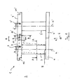
- FIG. 1 As seen in the axial direction, schematically shows a blade segment 1 according to an embodiment of the present invention.
- the blade segment 1 is part of a turbomachine, in particular a turbomachine, which is generally designated 2.
- the turbomachine is preferably an aircraft engine.
- the blade segment 1 has two blades 3 and 3 'on the blades 3, 3' are preferably formed as blades.
- the blades 3, 3 ' are with their respective feet 4, 4' in a rotor 5, see FIG. 4 , For example by means of a Christmas tree connection, attached.
- the rotor 5 rotates about an axis 6, wherein the blades 3, 3 'interact with a fluid flowing through the turbomachine 2.
- the terms "in the circumferential direction”, “in the radial direction” and “in the axial direction” refer hereinafter to the axis 6. It should be noted that the axis 6 is located in reality much further away from the blades 3, 3 ', as in FIG. 1 shown.
- the blades 3, 3 ' are each connected to shrouds 7, 7'.
- the shrouds 7, 7 'each have a center of gravity S, S', which has a distance D, D 'on a central axis M, M' of a respective blade 3, 3 '.
- the central axes M, M 'each extend through the axis 6, which due to the highly schematic representation in FIG. 1 is not recognizable.
- the central axis M extends through a center of gravity SB of the blade 3, see FIG. 2 ,
- the center of gravity SB is the center of gravity of the profile of the blade 3. The same applies to the central axis M 'of the blade 3'.
- a respective shroud 7, 7 ' has a contact surface 11, 11' and a counter-contact surface 12, 12 'lying opposite it.
- the contact surfaces 11, 11 'and counter-contact surfaces 12, 12' may each be formed at the ends of the shrouds 7, 7 'in the circumferential direction U.
- FIG. 2 shows a section A-A from FIG. 1.
- FIG. 3 shows a section B-B from FIG. 1.
- "Sloping" means an angle W 'other than 90 degrees and preferably between 45 and 135 Degree.
- the base inclination axis G 'of the blade 3' may be inclined for example by 1 degree in the direction of the axis of rotation 6.
- a contact pressure AK results between the contact surface 11 and the counter-contact surface 12 '. Due to the oblique arrangement of the contact surface 11 and the counter-contact surface 12 ', the contact force AK results in a reaction force RK1 and a reaction force RK2, which act on the blade 3. RK2 acts along the base pitch axis G 'and RK1 perpendicular thereto.
- RK1 is also in FIG. 2 shown. Here it can be seen that RK1 generates an additional torsional moment TR about the center of gravity SB or the center axis M of the blade 3, which counteracts a winding E of the blade 3.
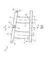
- FIG. 4 1 shows the vane segment FIG. 1 in a perspective view obliquely from below.
- the shrouds 7, 7 'at their opposite ends preferably in the region of the contact surfaces 11, 11' and counter-bearing surfaces 12, 12 'engaging elements 13, 13' and receiving elements 14, 14 'on.
- the engagement element 13 'of the shroud 7' engages in the circumferential direction in the receiving element 14 of the shroud 7 a. This results in a form fit in the axial direction, which unwinding of the blades 3, 3 'at a standstill of the blade segment 1 or at low speeds, where the frictional engagement RF is still too low to couple the blades 3, 3' together prevented ,
- Fig. 5 As seen in the axial direction, schematically shows a blade segment 1 according to another embodiment of the present invention.
- the blade segment 1 differs from that according to the Fig. 1 to 4 only in the way the friction fit RF is generated. Incidentally, therefore, the comments on the Fig. 1 to 4 according to the blade segment Fig. 5 ,
- the frictional engagement RF in the embodiment according to Fig. 5 is advantageous not or only slightly dependent on speed.
Landscapes
- Engineering & Computer Science (AREA)
- Mechanical Engineering (AREA)
- General Engineering & Computer Science (AREA)
- Turbine Rotor Nozzle Sealing (AREA)
- Structures Of Non-Positive Displacement Pumps (AREA)
Abstract
Description
- Die vorliegende Erfindung betrifft ein Schaufelsegment sowie eine Strömungsmaschine.
- Beispielsweise ist es aus der Druckschrift
JP 2007154695 A - Aufgabe der vorliegenden Erfindung ist es, einen alternativen oder ergänzenden Ansatz bereitzustellen, welcher eine Kopplung zwischen wenigstens zwei Schaufeln eines Schaufelsegments vorsieht, um ein günstiges Dämpfungsverhalten zu erzielen.
- Diese Aufgabe wird gelöst durch ein Schaufelsegment mit Merkmalen des Patentanspruchs 1 sowie durch eine Strömungsmaschine mit dem Merkmal des Patentanspruchs 10.
- Demgemäß wird ein Schaufelsegment für eine Strömungsmaschine, aufweisend: eine erste Schaufel; ein erstes, mit der Spitze der ersten Schaufel verbundenes Deckband, welches eine Anlagefläche aufweist; eine zweite Schaufel; und ein zweites, mit der Spitze der zweiten Schaufel verbundenes zweites Deckband, welches eine Gegenanlagefläche für ein Anliegen der Anlagefläche des ersten Deckbandes in radialer Richtung derart aufweist, dass ein Reibschluss zwischen der Anlagefläche und der Gegenanlagefläche erzeugbar ist; bereitgestellt.
- Weiterhin wird eine Strömungsmaschine, insbesondere Turbomaschine, mit dem erfindungsgemäßen Schaufelsegment bereitgestellt.
- Die der vorliegenden Erfindung zugrunde liegende Idee besteht darin, die Deckbänder der jeweiligen Schaufeln dachziegelartig anzuordnen, sodass die Deckbänder in der radialen Richtung derart gegeneinander anliegen, dass zumindest im Betrieb des Schaufelsegments (oder auch im Stillstand desselben) ein Reibschluss zwischen einander überlappenden Deckbändern gebildet wird. Der Reibschluss sorgt für ein Kopplung der Deckbänder bzw. der Schaufeln miteinander, was im Hinblick auf ein Dämpfungsverhalten günstig ist.
- Aus den Unteransprüchen ergeben sich vorteilhafte Ausgestaltungen.
- Unter dem Anliegen der Anlagefläche gegen die Gegenanlagefläche in der radialen Richtung ist vorliegend zu verstehen, dass ein Vektor senkrecht auf die Ebene, in welcher die Anlagefläche und die Gegenanlagefläche gegeneinander anliegen, zumindest eine radiale Komponente auf weist.
- "Umfangsrichtung" meint vorliegend eine Richtung entlang einer Kreislinie, welche die Drehachse des Schaufelsegments in der Strömungsmaschine als Mittelachse besitzt. "Radial" bezieht sich vorliegend auf eine Richtung senkrecht zu der Drehachse des Schaufelsegments in der Strömungsmaschine. "Axial" bezieht sich vorliegend auf eine Richtung entlang der Drehachse des Schaufelsegments in der Strömungsmaschine.
- Gemäß einer Ausgestaltung des erfindungsgemäßen Schaufelsegments ist der Schwerpunkt des ersten Deckbandes in Umfangsrichtung von einer Mittelachse der ersten Schaufel derart beabstandet angeordnet, dass sich die erste Schaufel unter Einwirkung der Fliehkräfte im Betrieb des Schaufelsegments für das Erzeugen des Reibschlusses zwischen der Anlagefläche und der Gegenanlagefläche verbiegt. Im Betrieb des Schaufelsegments entsteht also unter Einwirkung der wirkenden Fliehkräfte ein Biegemoment, welches dazu tendiert, die Schaufel samt dem Deckband in Umfangsrichtung zu kippen. Dieses Kippen wird aber mittels der Anlagefläche des ersten Deckbands und der Gegenanlagefläche des zweiten Deckbands verhindert. Die Anlagefläche drückt dabei in der radialen Richtung derart gegen die Gegenanlagefläche, dass es zu einem Reibschluss zwischen der Anlagefläche und der Gegenanlagefläche kommt.
- Mit "Mittelachse" ist vorliegend die Achse der ersten Schaufel gemeint, die derart positioniert ist, dass, wenn der Schwerpunkt des ersten Deckbands, mit dieser koinzident angeordnet wäre, kein oder nur ein unwesentliches Biegemoment aus dem Deckband in die erste Schaufel eingeleitet werden würde. Entsprechendes gilt für die Mittelachse der zweiten Schaufel.
- Gemäß einer Ausgestaltung des erfindungsgemäßen Schaufelsegments ist die Anlagefläche des ersten Deckbandes und/oder die Gegenanlagefläche des zweiten Deckbandes mit einem Pressmaß in radialer Richtung für ein Verbiegen der ersten Schaufel um deren Fußpunkt in der Umfangsrichtung gebildet, um dadurch den Reibschlusses zwischen der Anlagefläche und der Gegenanlagefläche zu erzeugen. Mit einem Pressmaß ist gemeint, dass die Anlagefläche und/oder Gegenanlagefläche in der radialen Richtung aufgedickt ist, um dadurch eine Flächenpressung und damit einen Reibschluss zwischen der Anlagefläche und der Gegenanlagefläche zu erzeugen. Diese Ausgestaltung kann alternativ oder zusätzlich zu der vorhergehenden Ausgestaltung vorgesehen werden, bei welcher der Schwerpunkt des ersten Deckbandes in Umfangsrichtung von einer Mittelachse der ersten Schaufel derart beabstandet angeordnet.
- Gemäß einer weiteren Ausgestaltung des erfindungsgemäßen Schaufelsegments ist der Reibschluss dazu ausgebildet, ein Torsionsreaktionsmoment in einer Richtung um die Mittelachse der ersten und der zweiten Schaufel zu erzeugen. Dies ist zur Kompensation der Entwindungsneigung von radial verdrehten Laufschaufelprofilen günstig.
- Gemäß einer weiteren Ausgestaltung des erfindungsgemäßen Schaufelsegments weisen die erste und/oder zweite Schaufel eine Grundneigung in axialer Richtung auf, welche durch eine Grundneigungsachse definiert ist, wobei die Anlagefläche und Gegenanlagefläche schräg, insbesondere unter einem Winkel zwischen 45 und 135 Grad, in Bezug auf die Grundneigungsachse in axialer Richtung der ersten und der zweiten Schaufel angeordnet sind. Die Grundneigung wird auch als "lean" bezeichnet. Die Grundneigung dient üblicherweise dazu, die während des Betriebs der Strömungsmaschine auftretenden Gaskräfte, welche entsprechende Biegemomente an den Schaufeln erzeugen, zumindest in bestimmten Betriebsbereichen der Strömungsmaschine weitgehend auszugleichen. Die Grundneigung beträgt dabei in Abhängigkeit der Ausgestaltung der Strömungsmaschine üblicherweise zwischen 0 und 2 Grad. Die schräge Anordnung von Anlagefläche und Gegenanlagefläche führt dazu, dass ein Torsionsmoment um die Mittelachse einer jeweiligen Schaufel entsteht, welches einer Entwindung einer jeweiligen Schaufel entgegenwirken kann. Hier sind zwei spiegelbildliche Anordnungen möglich. Dieses Torsionsmoment nimmt zu, je stärker die Anlagefläche gegen die Gegenanlagefläche drückt.
- Gemäß einer weiteren Ausgestaltung des erfindungsgemäßen Schaufelsegments weisen die Anlageflächen und Gegenanlageflächen ein Eingriffselement und ein Aufnahmeelement auf, welche in der Umfangsrichtung ineinander eingreifen. Dadurch werden das erste und zweite Deckband noch besser, also zusätzlich zu dem Reibschluss, aneinander abgestützt. Insbesondere verhindert diese Ausgestaltung eine Entwindung der Schaufeln dann, wenn kein Reibschluss erzeugt wird (beispielsweise im Stillstand des Schaufelsegments bei der Ausgestaltung mit dem in Umfangsrichtung versetzten Schwerpunkt des Deckbandes).
- Gemäß einer weiteren Ausgestaltung des erfindungsgemäßen Schaufelsegments ist die erste und/oder zweite Schaufel torsionsvorgespannt. Stehen die Schaufeln mittels der vorstehend beschriebenen Eingriffs- und Aufnahmeelemente miteinander in Eingriff, ist es beispielsweise möglich die Schaufeln auch torsionsvorzuspannen, sodass auch bei niedrigen Drehzahlen ein ausreichende Kopplung zwischen den Schaufeln erreicht wird, welche ein günstiges Dämpfungsverhalten bewirkt. Der Reibschluss auf Grund des Versatzes des Schwerpunktes eines jeweiligen Deckbandes mag bei den niedrigen Drehzahlen noch nicht genügen, um eine derart ausreichende Kopplung zwischen den Deckbändern zu erzielen.
- Gemäß einer weiteren Ausgestaltung des erfindungsgemäßen Schaufelsegments sind die erste und zweite Schaufel als Laufschaufeln ausgebildet.
- Gemäß einer weiteren Ausgestaltung des erfindungsgemäßen Schaufelsegments sind die erste und zweite Schaufel aus einem stark kriechenden Material. Mit "stark kriechenden Materialien" sind solche Werkstoffe gemeint, die stärker kriechen als aktuelle Nickelwerkstoffe.
- Die Erfindung wird nachfolgend anhand von Ausführungsbeispielen unter Bezugnahme auf die beiliegenden Figuren der Zeichnungen näher erläutert.
- Es zeigen:
- Figur 1
- in axialer Richtung gesehen, schematisch ein Schaufelsegment gemäß einem Ausführungsbeispiel der vorliegenden Erfindung;
- Figur 2
- einen Schnitt A-A aus
Figur 1 , - Figur 3
- einen Schnitt B-B aus
Figur 1 , - Figur 4
- in einer perspektivischen Ansicht von schräg unten das Schaufelsegment gemäß
Figur 1 ; und - Figur 5
- in axialer Richtung gesehen, schematisch ein Schaufelsegment gemäß einem weiteren Ausführungsbeispiel der vorliegenden Erfindung;
- In den Figuren bezeichnen gleiche Bezugsziffern gleiche oder funktionsgleiche Komponenten, soweit nichts Gegenteiliges angegeben ist.
-
Figur 1 zeigt in axialer Richtung gesehen, schematisch ein Schaufelsegment 1 gemäß einem Ausführungsbeispiel der vorliegenden Erfindung. - Das Schaufelsegment 1 ist Bestandteil einer Strömungsmaschine, insbesondere einer Turbomaschine, welche allgemein mit 2 bezeichnet ist. Bevorzugt handelt es sich bei der Turbomaschine um ein Flugtriebwerk.
- Das Schaufelsegment 1 weist zwei Schaufeln 3 und 3'auf Die Schaufeln 3, 3' sind bevorzugt als Laufschaufeln ausgebildet. Die Schaufeln 3, 3' sind mit ihren jeweiligen Füßen 4, 4' in einem Rotor 5, siehe
Figur 4 , beispielsweise mittels einer Tannenbaumverbindung, befestigt. Der Rotor 5 dreht um eine Achse 6, wobei die Schaufeln 3, 3' mit einem die Strömungsmaschine 2 durchströmenden Fluid in Wechselwirkung treten. Die Begriffe "in Umfangsrichtung", "in radialer Richtung" und "in axialer Richtung" beziehen sich nachfolgend auf die Achse 6. Es sei angemerkt, dass sich die Achse 6 in der Realität deutlich weiter von den Schaufeln 3, 3' entfernt befindet, als inFigur 1 dargestellt. - An ihren Spitzen, also radial außenseitig, sind die Schaufeln 3, 3' jeweils mit Deckbändern 7, 7' verbunden. Die Schaufeln 3, 3', samt ihrer Füße 4, 4' und Deckbänder 7, 7' sind in der Umfangsrichtung U nebeneinander angeordnet und bilden bevorzugt einen geschlossenen Ring aus, wobei in
Figur 1 lediglich ein Ausschnitt mit zwei der Schaufeln 3, 3' dargestellt ist. Die Deckbänder 7, 7' sind in axialer Richtung dachziegelartig übereinander angeordnet. - Die Deckbänder 7, 7' weisen jeweils einen Schwerpunkt S, S' auf, welcher einen Abstand D, D' auf eine Mittelachse M, M' einer jeweiligen Schaufel 3, 3' aufweist. Die Mittelachsen M, M' verlaufen jeweils durch die Achse 6, was aufgrund der stark schematisierten Darstellung in
Figur 1 nicht erkennbar ist. Die Mittelachse M verläuft dabei durch einen Schwerpunkt SB der Schaufel 3, sieheFigur 2 . Der Schwerpunkt SB ist der Schwerpunkt des Profils der Schaufel 3. Entsprechendes gilt für die Mittelachse M' der Schaufel 3'. - Ein jeweiliges Deckband 7, 7' weist eine Anlagefläche 11, 11' und eine dieser gegenüberliegende Gegenanlagefläche 12, 12' auf. Die Anlageflächen 11, 11' und Gegenanlageflächen 12, 12' können jeweils an Enden der Deckbänder 7, 7' in Umfangsrichtung U ausgebildet sein.
- Weist das Schaufelsegment 1 keine oder nur eine geringe Drehzahl auf, so wirken keine oder nahezu keine Fliehkräfte auf die Schaufeln 3, 3' samt ihrer Deckbänder 7, 7'. Die Schaufeln 3, 3' samt Deckbänder 7, 7' befinden sich dann in der in
Figur 1 lediglich für die linke Schaufel 3 in gestrichelter Linie gezeichneten Stellung. Steigt die Drehzahl des Schaufelsegments 1, so nimmt ein Biegemoment des Deckbands 7 um einen Schaufelfußpunkt F zu. Dies, weil der Schwerpunkt S den Abstand D auf die Mittellinie M bzw. den Schwerpunkt SB der Schaufel 3 aufweist. Das resultierende Biegemoment ist inFigur 1 mit BM bezeichnet. Das Biegemoment BM bewirkt, dass die Schaufel 3 samt dem Deckband 7 aus ihrer gestrichelten Stellung inFigur 1 in ihre in durchgezogener Linie dargestellte Stellung kippt, d.h. sich verbiegt. Ab einer gewissen Drehzahl kommt die Anlagefläche 11 mit der Gegenanlagefläche 12' in der radialen Richtung R in Anlage, d.h., dass ein Vektor 9, sieheFig. 3 , senkrecht auf die Ebene 10, in welcher die Anlagefläche 11 und die Gegenanlagefläche 12' gegeneinander anliegen, zumindest eine Komponente in der radialen Richtung R aufweist. Dabei entsteht ein Reibschluss zwischen der Anlagefläche 11 und der Gegenanlagefläche 12'. Von diesem Zeitpunkt an ist die Schaufel 3 mit der Schaufel 3' reibschlüssig gekoppelt, was sich im Hinblick auf ein Vibrationsverhalten dieser vorteilhaft auswirkt. - In
Figur 2 ist zu erkennen, dass der Reibschluss RF zwischen der Anlagefläche 11 und der Gegenanlagefläche 12' derart ausgebildet sein kann, dass dieser ein Torsionsreaktionsmoment TM um die Mittelachse M erzeugt, was die Schaufel 3 daran hindert, dass diese um die Mittelachse in ungewünschter Weise schwingt. - Wie
Figur 3 zu entnehmen, können die Anlagefläche 11 und die Gegenanlagefläche 12' in Bezug auf eine Grundneigungsachse G' schräg unter einem Winkel W' von bspw. 93 Grad angeordnet sein. "Schräg" meint einen Winkel W' ungleich 90 Grad und bevorzugt zwischen 45 und 135 Grad. Die Grundneigungsachse G' der Schaufel 3' kann beispielsweise um 1 Grad in Richtung der Drehachse 6 geneigt sein. - Unter der Einwirkung der Fliehkräfte und einer entsprechenden Entwindung der Schaufel 3 ergibt sich eine Anpresskraft AK zwischen der Anlagefläche 11 und der Gegenanlagefläche 12'. Aufgrund der schrägen Anordnung der Anlagefläche 11 sowie der Gegenanlagefläche 12' resultiert die Anlagekraft AK in einer Reaktionskraft RK1 und eine Reaktionskraft RK2, welche auf die Schaufel 3 rückwirken. RK2 wirkt entlang der Grundneigungsachse G' und RK1 senkrecht zu dieser.
- RK1 ist auch in
Figur 2 dargestellt. Hier ist zu erkennen, dass RK1 ein zusätzliches Torsionsmoment TR um den Schwerpunkt SB bzw. die Mittelachse M der Schaufel 3 erzeugt, welches einer Entwindung E der Schaufel 3 entgegenwirkt. -
Figur 4 zeigt das Schaufelsegment aus 1 ausFigur 1 in einer perspektivischen Ansicht von schräg unten. - Wie in
Figur 4 dargestellt, weisen die Deckbänder 7, 7' an ihren gegenüberliegenden Enden bevorzugt im Bereich der Anlageflächen 11, 11' und Gegenanlageflächen 12, 12' Eingriffselemente 13, 13' und Aufnahmeelemente 14, 14' auf. Das Eingriffselement 13' des Deckbands 7' greift in der Umfangsrichtung in das Aufnahmeelement 14 des Deckbands 7 ein. Dadurch ergibt sich ein Formschluss in der axialen Richtung, welcher eine Entwindung der Schaufeln 3, 3' im Stillstand des Schaufelsegments 1 oder bei niedrigen Drehzahlen, wo der Reibschluss RF noch zu gering ist, um die Schaufeln 3, 3' miteinander zu koppeln, verhindert. -
Fig. 5 zeigt in axialer Richtung gesehen, schematisch ein Schaufelsegment 1 gemäß einem weiteren Ausführungsbeispiel der vorliegenden Erfindung. - Das Schaufelsegment 1 unterscheidet sich von dem gemäß den
Fig. 1 bis 4 lediglich auf die Art und Weise, wie der Reibschluss RF erzeugt wird. Im Übrigen gelten daher die Ausführungen zu denFig. 1 bis 4 entsprechend für das Schaufelsegment nachFig. 5 . - Bei dem Schaufelsegment 1 nach
Fig. 5 ist die Anlagefläche 11 des Deckbandes 7 mit einem Pressmaß P in radialer Richtung R für ein Verbiegen der ersten Schaufel 3 um deren Fußpunkt F in der Umfangsrichtung U gebildet, um dadurch den Reibschlusses RF zwischen der Anlagefläche 11 und der Gegenanlagefläche 12' zu erzeugen. Entsprechendes gilt selbstverständlich auch für die weiteren Schaufeln des Schaufelsegments. - Der Reibschluss RF bei dem Ausführungsbeispiel nach
Fig. 5 ist vorteilhaft nicht oder nur unwesentlich drehzahlabhängig. - Die Ausgestaltungen nach den
Fig. 1 bis 4 und nachFig. 5 können auch miteinander kombiniert werden. - Obwohl die Erfindung vorliegend anhand bevorzugter Ausführungsbeispiele beschrieben wurde, ist sie darauf nicht beschränkt, sondern vielfältige Weise modifizierbar.
-
- 1
- Schaufelsegment
- 2
- Strömungsmaschine
- 3
- Schaufel
- 3'
- Schaufel
- 4
- Fuß
- 4'
- Fuß
- 5
- Rotor
- 6
- Drehachse
- 7
- Deckband
- 7'
- Deckband
- 9
- Vektor
- 10
- Ebene
- 11
- Anlagefläche
- 11'
- Anlagefläche
- 12
- Gegenanlagefläche
- 12'
- Gegenanlagefläche
- 13
- Eingriffselement
- 13'
- Eingriffselement
- 14
- Aufnahmeelement
- 14'
- Aufnahmeelement
- D
- Abstand
- F
- Fußpunkt
- G'
- Grundneigungsachse
- M
- Mittelachse
- M'
- Mittelachse
- R
- radiale Richtung
- S
- Schwerpunkt
- S'
- Schwerpunkt
- U
- Umfangsrichtung
- AK
- Anlagekraft
- BM
- Biegemoment
- RF
- Reibkraft
- RK1
- Reaktionskraft
- RK2
- Reaktionskraft
- SB
- Schaufelschwerpunkt
- TM
- Torsionsreaktionsmoment
- TR
- Torsionsmoment
- E
- Entwindung
Claims (10)
- Schaufelsegment (1) für eine Strömungsmaschine (2), aufweisend:eine erste Schaufel (3);ein erstes, mit einer Spitze der ersten Schaufel (3) verbundenes Deckband (7), welches eine Anlagefläche (11) aufweist;eine zweite Schaufel (3'); undein zweites, mit einer Spitze der zweiten Schaufel (3') verbundenes zweites Deckband (7'), welches eine Gegenanlagefläche (12') für ein Anliegen der Anlagefläche (11) des ersten Deckbandes (7) in radialer Richtung (R) derart aufweist, dass ein Reibschluss (RF) zwischen der Anlagefläche (11) und der Gegenanlagefläche (12') erzeugbar ist.
- Schaufelsegment nach Anspruch 1,
dadurch gekennzeichnet,
dass der Schwerpunkt (S) des ersten Deckbandes (7) in Umfangsrichtung (U) von einer Mittelachse (M) der ersten Schaufel (3) derart beabstandet angeordnet ist, dass sich die erste Schaufel (3) unter Einwirkung der Fliehkräfte im Betrieb des Schaufelsegments (1) für das Erzeugen des Reibschlusses (RF) zwischen der Anlagefläche (11) und der Gegenanlagefläche (12') verbiegt. - Schaufelsegment nach Anspruch 1 oder 2,
dadurch gekennzeichnet,
dass die Anlagefläche (11) des ersten Deckbandes (7) und/oder die Gegenanlagefläche (12') des zweiten Deckbandes (7') mit einem Pressmaß (P) in radialer Richtung (R) für ein Verbiegen der ersten Schaufel (3) um deren Fußpunkt (F) in der Umfangsrichtung (U) gebildet sind, um dadurch den Reibschlusses (RF) zwischen der Anlagefläche (11) und der Gegenanlagefläche (12') zu erzeugen. - Schaufelsegment nach einem der vorhergehenden Ansprüche,
dadurch gekennzeichnet,
dass der Reibschluss (RF) dazu ausgebildet ist, ein Torsionsreaktionsmoment (TM) in einer Richtung um die Mittelachse (M) der erste und/oder zweiten Schaufel (3) zu erzeugen. - Schaufelsegment nach einem der vorhergehenden Ansprüche,
dadurch gekennzeichnet,
dass die erste und/oder zweite Schaufel (3') eine Grundneigung in axialer Richtung (6) aufweisen, welche durch eine Grundneigungsachse (G') definiert ist, wobei die Anlagefläche (11) und Gegenanlagefläche (12') schräg, insbesondere unter einem Winkel (W') zwischen 45 und 135 Grad, in Bezug auf die Grundneigungsachse (G') der ersten und/oder zweiten Schaufel (3') angeordnet sind. - Schaufelsegment nach einem der vorhergehenden Ansprüche,
dadurch gekennzeichnet,
dass die Anlagefläche (11) und Gegenanlagefläche (12') ein Eingriffselement (13') und ein Aufnahmeelement (14) aufweisen, welche in der Umfangsrichtung (U) ineinander eingreifen. - Schaufelsegment nach einem der vorhergehenden Ansprüche,
dadurch gekennzeichnet,
dass die erste und/oder zweite Schaufel (3, 3') torsionsvorgespannt ist. - Schaufelsegment nach einem der vorhergehenden Ansprüche,
dadurch gekennzeichnet,
dass die erste und zweite Schaufel (3, 3') als Laufschaufeln ausgebildet sind. - Schaufelsegment nach einem der vorhergehenden Ansprüche,
dadurch gekennzeichnet,
dass die erste und/oder zweite Schaufel (3, 3') aus einem stark kriechenden Material ausgebildet ist. - Strömungsmaschine (2), insbesondere Turbine, mit einem Schaufelsegment (1) nach einem der vorhergehenden Ansprüche.
Priority Applications (3)
| Application Number | Priority Date | Filing Date | Title |
|---|---|---|---|
| EP10193687A EP2460979B1 (de) | 2010-12-03 | 2010-12-03 | Schaufelsegment einer Strömungsmaschine mit radialen Anlageflächen |
| ES10193687T ES2401350T3 (es) | 2010-12-03 | 2010-12-03 | Segmento de paletas y turbina con superficies de asiento radiales |
| US13/310,939 US20120141259A1 (en) | 2010-12-03 | 2011-12-05 | Blade segment and fluid flow machine |
Applications Claiming Priority (1)
| Application Number | Priority Date | Filing Date | Title |
|---|---|---|---|
| EP10193687A EP2460979B1 (de) | 2010-12-03 | 2010-12-03 | Schaufelsegment einer Strömungsmaschine mit radialen Anlageflächen |
Publications (2)
| Publication Number | Publication Date |
|---|---|
| EP2460979A1 true EP2460979A1 (de) | 2012-06-06 |
| EP2460979B1 EP2460979B1 (de) | 2013-02-13 |
Family
ID=43754720
Family Applications (1)
| Application Number | Title | Priority Date | Filing Date |
|---|---|---|---|
| EP10193687A Not-in-force EP2460979B1 (de) | 2010-12-03 | 2010-12-03 | Schaufelsegment einer Strömungsmaschine mit radialen Anlageflächen |
Country Status (3)
| Country | Link |
|---|---|
| US (1) | US20120141259A1 (de) |
| EP (1) | EP2460979B1 (de) |
| ES (1) | ES2401350T3 (de) |
Cited By (1)
| Publication number | Priority date | Publication date | Assignee | Title |
|---|---|---|---|---|
| WO2023247857A1 (fr) * | 2022-06-22 | 2023-12-28 | Safran Aircraft Engines | Ensemble aubage de turbomachine comportant des moyens de limitations de vibrations entre plateformes |
Citations (8)
| Publication number | Priority date | Publication date | Assignee | Title |
|---|---|---|---|---|
| GB861728A (en) * | 1958-09-29 | 1961-02-22 | Parsons & Marine Eng Turbine | Improvements in and relating to elastic fluid turbines |
| GB2139295A (en) * | 1983-05-05 | 1984-11-07 | Tuomo Kaivola | Thermal joint e.g. for a turbine |
| US20060127221A1 (en) * | 2002-09-02 | 2006-06-15 | Yutaka Yamashita | Turbine moving blade |
| JP2007154695A (ja) | 2005-12-01 | 2007-06-21 | Toshiba Corp | タービン動翼および蒸気タービン |
| US20070224043A1 (en) * | 2006-03-27 | 2007-09-27 | Alstom Technology Ltd | Turbine blade and diaphragm construction |
| EP1840333A1 (de) * | 2006-03-31 | 2007-10-03 | ALSTOM Technology Ltd | Turbinenschaufel mit Deckbandteile |
| EP1873355A1 (de) * | 2006-06-27 | 2008-01-02 | Siemens Aktiengesellschaft | Turbinenschaufel |
| WO2008084038A1 (en) * | 2007-01-12 | 2008-07-17 | Alstom Technology Ltd | Diaphragm for turbomachines and method of manufacture |
Family Cites Families (5)
| Publication number | Priority date | Publication date | Assignee | Title |
|---|---|---|---|---|
| FR1033197A (fr) * | 1951-02-27 | 1953-07-08 | Rateau Soc | Amortisseurs de vibrations pour aubages mobiles de turbo-machines |
| GB1194061A (en) * | 1968-01-17 | 1970-06-10 | Rolls Royce | Improvements relating to Pressure Exchanger Rotors |
| JP2001248404A (ja) * | 2000-03-01 | 2001-09-14 | Hitachi Ltd | タ一ビン動翼 |
| JP2002371802A (ja) * | 2001-06-14 | 2002-12-26 | Mitsubishi Heavy Ind Ltd | ガスタービンにおけるシュラウド一体型動翼と分割環 |
| US20080145227A1 (en) * | 2006-12-19 | 2008-06-19 | Mark Stefan Maier | Methods and apparatus for load transfer in rotor assemblies |
-
2010
- 2010-12-03 EP EP10193687A patent/EP2460979B1/de not_active Not-in-force
- 2010-12-03 ES ES10193687T patent/ES2401350T3/es active Active
-
2011
- 2011-12-05 US US13/310,939 patent/US20120141259A1/en not_active Abandoned
Patent Citations (8)
| Publication number | Priority date | Publication date | Assignee | Title |
|---|---|---|---|---|
| GB861728A (en) * | 1958-09-29 | 1961-02-22 | Parsons & Marine Eng Turbine | Improvements in and relating to elastic fluid turbines |
| GB2139295A (en) * | 1983-05-05 | 1984-11-07 | Tuomo Kaivola | Thermal joint e.g. for a turbine |
| US20060127221A1 (en) * | 2002-09-02 | 2006-06-15 | Yutaka Yamashita | Turbine moving blade |
| JP2007154695A (ja) | 2005-12-01 | 2007-06-21 | Toshiba Corp | タービン動翼および蒸気タービン |
| US20070224043A1 (en) * | 2006-03-27 | 2007-09-27 | Alstom Technology Ltd | Turbine blade and diaphragm construction |
| EP1840333A1 (de) * | 2006-03-31 | 2007-10-03 | ALSTOM Technology Ltd | Turbinenschaufel mit Deckbandteile |
| EP1873355A1 (de) * | 2006-06-27 | 2008-01-02 | Siemens Aktiengesellschaft | Turbinenschaufel |
| WO2008084038A1 (en) * | 2007-01-12 | 2008-07-17 | Alstom Technology Ltd | Diaphragm for turbomachines and method of manufacture |
Cited By (3)
| Publication number | Priority date | Publication date | Assignee | Title |
|---|---|---|---|---|
| WO2023247857A1 (fr) * | 2022-06-22 | 2023-12-28 | Safran Aircraft Engines | Ensemble aubage de turbomachine comportant des moyens de limitations de vibrations entre plateformes |
| FR3137120A1 (fr) * | 2022-06-22 | 2023-12-29 | Safran Aircraft Engines | Ensemble aubagé de turbomachine comportant des moyens de limitations de vibrations entre plateformes |
| US12486775B1 (en) | 2022-06-22 | 2025-12-02 | Safran Aircraft Engines | Turbomachine blading assembly comprising means for limiting vibration between platforms |
Also Published As
| Publication number | Publication date |
|---|---|
| US20120141259A1 (en) | 2012-06-07 |
| ES2401350T3 (es) | 2013-04-18 |
| EP2460979B1 (de) | 2013-02-13 |
Similar Documents
| Publication | Publication Date | Title |
|---|---|---|
| DE102005008509B4 (de) | Laufschaufelkörper und Rotationsmaschine mit einem Laufschaufelkörper | |
| DE2307967C2 (de) | Plattform für eine Verdichterschaufel | |
| DE2743563C2 (de) | Gasturbinen-Laufrad | |
| EP2846046B1 (de) | Ventilatorrad | |
| EP2452076B1 (de) | Laufrad für eine turbomaschine | |
| DE102009040504A1 (de) | Beschlag für einen Fahrzeugsitz | |
| DE102016112521B4 (de) | Laufrad für einen Abgasturbolader, Abgasturbolader und Verfahren zum Auswuchten eines Laufzeugs für einen Abgasturbolader | |
| EP3524781B1 (de) | Verbindungseinrichtung für eine verstellbare schaufel einer gasturbine | |
| DE3441399C2 (de) | ||
| EP2617945B1 (de) | Rotor für eine Strömungsmaschine sowie Verfahren zu dessen Herstellung | |
| EP3667020A1 (de) | Turbomaschinen-schaufelanordnung | |
| EP3025027B1 (de) | Turbinenschaufel sowie gasturbine | |
| EP1515001B1 (de) | Laufschaufelbindung einer Turbomaschine | |
| EP2460979B1 (de) | Schaufelsegment einer Strömungsmaschine mit radialen Anlageflächen | |
| DE2601568B2 (de) | Vorrichtung zum Verbinden von Turbinenschaufeln | |
| EP2310634B1 (de) | Laufschaufelsystem für eine laufschaufelreihe einer strömungsmaschine | |
| EP2404038B1 (de) | Integral beschaufelter rotor und verfahren zur herstellung eines integral beschaufelten rotors | |
| EP1507958A1 (de) | Axialsicherung fuer laufschaufeln | |
| EP3406860B1 (de) | Turbofantriebwerk | |
| DE1503527B2 (de) | Verstellvorrichtung für einen Kranz schwenkbarer Leitschaufeln | |
| DE19544313B3 (de) | Laufschaufel mit geschlitztem Schaft | |
| DE102009010502B4 (de) | Turbinenschaufelblatt, Turbinenschaufel und Turbine | |
| EP3724456B1 (de) | Rotor mit fliehkraft-optimierten kontaktflächen | |
| EP4277751A1 (de) | Messerzapfen für einen fleischwolf sowie fleischwolf mit einem solchen messerzapfen | |
| DE102016205921B4 (de) | Rotorscheibenanordnung mit zweiteiliger Dichtung |
Legal Events
| Date | Code | Title | Description |
|---|---|---|---|
| PUAI | Public reference made under article 153(3) epc to a published international application that has entered the european phase |
Free format text: ORIGINAL CODE: 0009012 |
|
| 17P | Request for examination filed |
Effective date: 20110504 |
|
| AK | Designated contracting states |
Kind code of ref document: A1 Designated state(s): AL AT BE BG CH CY CZ DE DK EE ES FI FR GB GR HR HU IE IS IT LI LT LU LV MC MK MT NL NO PL PT RO RS SE SI SK SM TR |
|
| AX | Request for extension of the european patent |
Extension state: BA ME |
|
| GRAP | Despatch of communication of intention to grant a patent |
Free format text: ORIGINAL CODE: EPIDOSNIGR1 |
|
| GRAS | Grant fee paid |
Free format text: ORIGINAL CODE: EPIDOSNIGR3 |
|
| GRAA | (expected) grant |
Free format text: ORIGINAL CODE: 0009210 |
|
| AK | Designated contracting states |
Kind code of ref document: B1 Designated state(s): AL AT BE BG CH CY CZ DE DK EE ES FI FR GB GR HR HU IE IS IT LI LT LU LV MC MK MT NL NO PL PT RO RS SE SI SK SM TR |
|
| REG | Reference to a national code |
Ref country code: GB Ref legal event code: FG4D Free format text: NOT ENGLISH |
|
| REG | Reference to a national code |
Ref country code: AT Ref legal event code: REF Ref document number: 596620 Country of ref document: AT Kind code of ref document: T Effective date: 20130215 |
|
| REG | Reference to a national code |
Ref country code: IE Ref legal event code: FG4D Free format text: LANGUAGE OF EP DOCUMENT: GERMAN |
|
| REG | Reference to a national code |
Ref country code: DE Ref legal event code: R096 Ref document number: 502010002307 Country of ref document: DE Effective date: 20130411 |
|
| REG | Reference to a national code |
Ref country code: ES Ref legal event code: FG2A Ref document number: 2401350 Country of ref document: ES Kind code of ref document: T3 Effective date: 20130418 |
|
| REG | Reference to a national code |
Ref country code: NL Ref legal event code: VDEP Effective date: 20130213 |
|
| REG | Reference to a national code |
Ref country code: LT Ref legal event code: MG4D |
|
| PG25 | Lapsed in a contracting state [announced via postgrant information from national office to epo] |
Ref country code: SE Free format text: LAPSE BECAUSE OF FAILURE TO SUBMIT A TRANSLATION OF THE DESCRIPTION OR TO PAY THE FEE WITHIN THE PRESCRIBED TIME-LIMIT Effective date: 20130213 Ref country code: LT Free format text: LAPSE BECAUSE OF FAILURE TO SUBMIT A TRANSLATION OF THE DESCRIPTION OR TO PAY THE FEE WITHIN THE PRESCRIBED TIME-LIMIT Effective date: 20130213 Ref country code: BG Free format text: LAPSE BECAUSE OF FAILURE TO SUBMIT A TRANSLATION OF THE DESCRIPTION OR TO PAY THE FEE WITHIN THE PRESCRIBED TIME-LIMIT Effective date: 20130513 Ref country code: IS Free format text: LAPSE BECAUSE OF FAILURE TO SUBMIT A TRANSLATION OF THE DESCRIPTION OR TO PAY THE FEE WITHIN THE PRESCRIBED TIME-LIMIT Effective date: 20130613 Ref country code: NO Free format text: LAPSE BECAUSE OF FAILURE TO SUBMIT A TRANSLATION OF THE DESCRIPTION OR TO PAY THE FEE WITHIN THE PRESCRIBED TIME-LIMIT Effective date: 20130513 |
|
| PG25 | Lapsed in a contracting state [announced via postgrant information from national office to epo] |
Ref country code: GR Free format text: LAPSE BECAUSE OF FAILURE TO SUBMIT A TRANSLATION OF THE DESCRIPTION OR TO PAY THE FEE WITHIN THE PRESCRIBED TIME-LIMIT Effective date: 20130514 Ref country code: SI Free format text: LAPSE BECAUSE OF FAILURE TO SUBMIT A TRANSLATION OF THE DESCRIPTION OR TO PAY THE FEE WITHIN THE PRESCRIBED TIME-LIMIT Effective date: 20130213 Ref country code: PL Free format text: LAPSE BECAUSE OF FAILURE TO SUBMIT A TRANSLATION OF THE DESCRIPTION OR TO PAY THE FEE WITHIN THE PRESCRIBED TIME-LIMIT Effective date: 20130213 Ref country code: LV Free format text: LAPSE BECAUSE OF FAILURE TO SUBMIT A TRANSLATION OF THE DESCRIPTION OR TO PAY THE FEE WITHIN THE PRESCRIBED TIME-LIMIT Effective date: 20130213 Ref country code: PT Free format text: LAPSE BECAUSE OF FAILURE TO SUBMIT A TRANSLATION OF THE DESCRIPTION OR TO PAY THE FEE WITHIN THE PRESCRIBED TIME-LIMIT Effective date: 20130613 Ref country code: FI Free format text: LAPSE BECAUSE OF FAILURE TO SUBMIT A TRANSLATION OF THE DESCRIPTION OR TO PAY THE FEE WITHIN THE PRESCRIBED TIME-LIMIT Effective date: 20130213 |
|
| PG25 | Lapsed in a contracting state [announced via postgrant information from national office to epo] |
Ref country code: RS Free format text: LAPSE BECAUSE OF FAILURE TO SUBMIT A TRANSLATION OF THE DESCRIPTION OR TO PAY THE FEE WITHIN THE PRESCRIBED TIME-LIMIT Effective date: 20130213 Ref country code: HR Free format text: LAPSE BECAUSE OF FAILURE TO SUBMIT A TRANSLATION OF THE DESCRIPTION OR TO PAY THE FEE WITHIN THE PRESCRIBED TIME-LIMIT Effective date: 20130213 |
|
| PG25 | Lapsed in a contracting state [announced via postgrant information from national office to epo] |
Ref country code: EE Free format text: LAPSE BECAUSE OF FAILURE TO SUBMIT A TRANSLATION OF THE DESCRIPTION OR TO PAY THE FEE WITHIN THE PRESCRIBED TIME-LIMIT Effective date: 20130213 Ref country code: SK Free format text: LAPSE BECAUSE OF FAILURE TO SUBMIT A TRANSLATION OF THE DESCRIPTION OR TO PAY THE FEE WITHIN THE PRESCRIBED TIME-LIMIT Effective date: 20130213 Ref country code: CZ Free format text: LAPSE BECAUSE OF FAILURE TO SUBMIT A TRANSLATION OF THE DESCRIPTION OR TO PAY THE FEE WITHIN THE PRESCRIBED TIME-LIMIT Effective date: 20130213 Ref country code: RO Free format text: LAPSE BECAUSE OF FAILURE TO SUBMIT A TRANSLATION OF THE DESCRIPTION OR TO PAY THE FEE WITHIN THE PRESCRIBED TIME-LIMIT Effective date: 20130213 Ref country code: DK Free format text: LAPSE BECAUSE OF FAILURE TO SUBMIT A TRANSLATION OF THE DESCRIPTION OR TO PAY THE FEE WITHIN THE PRESCRIBED TIME-LIMIT Effective date: 20130213 Ref country code: NL Free format text: LAPSE BECAUSE OF FAILURE TO SUBMIT A TRANSLATION OF THE DESCRIPTION OR TO PAY THE FEE WITHIN THE PRESCRIBED TIME-LIMIT Effective date: 20130213 |
|
| PLBE | No opposition filed within time limit |
Free format text: ORIGINAL CODE: 0009261 |
|
| STAA | Information on the status of an ep patent application or granted ep patent |
Free format text: STATUS: NO OPPOSITION FILED WITHIN TIME LIMIT |
|
| PG25 | Lapsed in a contracting state [announced via postgrant information from national office to epo] |
Ref country code: IT Free format text: LAPSE BECAUSE OF FAILURE TO SUBMIT A TRANSLATION OF THE DESCRIPTION OR TO PAY THE FEE WITHIN THE PRESCRIBED TIME-LIMIT Effective date: 20130213 |
|
| 26N | No opposition filed |
Effective date: 20131114 |
|
| REG | Reference to a national code |
Ref country code: DE Ref legal event code: R097 Ref document number: 502010002307 Country of ref document: DE Effective date: 20131114 |
|
| BERE | Be: lapsed |
Owner name: MTU AERO ENGINES G.M.B.H. Effective date: 20131231 |
|
| REG | Reference to a national code |
Ref country code: DE Ref legal event code: R119 Ref document number: 502010002307 Country of ref document: DE |
|
| PG25 | Lapsed in a contracting state [announced via postgrant information from national office to epo] |
Ref country code: LU Free format text: LAPSE BECAUSE OF FAILURE TO SUBMIT A TRANSLATION OF THE DESCRIPTION OR TO PAY THE FEE WITHIN THE PRESCRIBED TIME-LIMIT Effective date: 20131203 |
|
| REG | Reference to a national code |
Ref country code: DE Ref legal event code: R119 Ref document number: 502010002307 Country of ref document: DE Effective date: 20140701 |
|
| REG | Reference to a national code |
Ref country code: IE Ref legal event code: MM4A |
|
| REG | Reference to a national code |
Ref country code: FR Ref legal event code: ST Effective date: 20140829 |
|
| PG25 | Lapsed in a contracting state [announced via postgrant information from national office to epo] |
Ref country code: BE Free format text: LAPSE BECAUSE OF NON-PAYMENT OF DUE FEES Effective date: 20131231 Ref country code: IE Free format text: LAPSE BECAUSE OF NON-PAYMENT OF DUE FEES Effective date: 20131203 Ref country code: DE Free format text: LAPSE BECAUSE OF NON-PAYMENT OF DUE FEES Effective date: 20140701 |
|
| PG25 | Lapsed in a contracting state [announced via postgrant information from national office to epo] |
Ref country code: FR Free format text: LAPSE BECAUSE OF NON-PAYMENT OF DUE FEES Effective date: 20131231 |
|
| REG | Reference to a national code |
Ref country code: ES Ref legal event code: FD2A Effective date: 20150327 |
|
| PG25 | Lapsed in a contracting state [announced via postgrant information from national office to epo] |
Ref country code: ES Free format text: LAPSE BECAUSE OF NON-PAYMENT OF DUE FEES Effective date: 20131204 Ref country code: MC Free format text: LAPSE BECAUSE OF FAILURE TO SUBMIT A TRANSLATION OF THE DESCRIPTION OR TO PAY THE FEE WITHIN THE PRESCRIBED TIME-LIMIT Effective date: 20130213 |
|
| PG25 | Lapsed in a contracting state [announced via postgrant information from national office to epo] |
Ref country code: SM Free format text: LAPSE BECAUSE OF FAILURE TO SUBMIT A TRANSLATION OF THE DESCRIPTION OR TO PAY THE FEE WITHIN THE PRESCRIBED TIME-LIMIT Effective date: 20130213 |
|
| PG25 | Lapsed in a contracting state [announced via postgrant information from national office to epo] |
Ref country code: TR Free format text: LAPSE BECAUSE OF FAILURE TO SUBMIT A TRANSLATION OF THE DESCRIPTION OR TO PAY THE FEE WITHIN THE PRESCRIBED TIME-LIMIT Effective date: 20130213 Ref country code: CY Free format text: LAPSE BECAUSE OF FAILURE TO SUBMIT A TRANSLATION OF THE DESCRIPTION OR TO PAY THE FEE WITHIN THE PRESCRIBED TIME-LIMIT Effective date: 20130213 |
|
| PG25 | Lapsed in a contracting state [announced via postgrant information from national office to epo] |
Ref country code: HU Free format text: LAPSE BECAUSE OF FAILURE TO SUBMIT A TRANSLATION OF THE DESCRIPTION OR TO PAY THE FEE WITHIN THE PRESCRIBED TIME-LIMIT; INVALID AB INITIO Effective date: 20101203 Ref country code: MK Free format text: LAPSE BECAUSE OF FAILURE TO SUBMIT A TRANSLATION OF THE DESCRIPTION OR TO PAY THE FEE WITHIN THE PRESCRIBED TIME-LIMIT Effective date: 20130213 |
|
| REG | Reference to a national code |
Ref country code: CH Ref legal event code: PL |
|
| GBPC | Gb: european patent ceased through non-payment of renewal fee |
Effective date: 20141203 |
|
| PG25 | Lapsed in a contracting state [announced via postgrant information from national office to epo] |
Ref country code: MT Free format text: LAPSE BECAUSE OF FAILURE TO SUBMIT A TRANSLATION OF THE DESCRIPTION OR TO PAY THE FEE WITHIN THE PRESCRIBED TIME-LIMIT Effective date: 20130213 |
|
| PG25 | Lapsed in a contracting state [announced via postgrant information from national office to epo] |
Ref country code: CH Free format text: LAPSE BECAUSE OF NON-PAYMENT OF DUE FEES Effective date: 20141231 Ref country code: GB Free format text: LAPSE BECAUSE OF NON-PAYMENT OF DUE FEES Effective date: 20141203 Ref country code: LI Free format text: LAPSE BECAUSE OF NON-PAYMENT OF DUE FEES Effective date: 20141231 |
|
| REG | Reference to a national code |
Ref country code: AT Ref legal event code: MM01 Ref document number: 596620 Country of ref document: AT Kind code of ref document: T Effective date: 20151203 |
|
| PG25 | Lapsed in a contracting state [announced via postgrant information from national office to epo] |
Ref country code: AT Free format text: LAPSE BECAUSE OF NON-PAYMENT OF DUE FEES Effective date: 20151203 |
|
| PG25 | Lapsed in a contracting state [announced via postgrant information from national office to epo] |
Ref country code: AL Free format text: LAPSE BECAUSE OF FAILURE TO SUBMIT A TRANSLATION OF THE DESCRIPTION OR TO PAY THE FEE WITHIN THE PRESCRIBED TIME-LIMIT Effective date: 20130213 |