EP2460692A2 - Load carrier with a powered fastening device - Google Patents
Load carrier with a powered fastening device Download PDFInfo
- Publication number
- EP2460692A2 EP2460692A2 EP11009410A EP11009410A EP2460692A2 EP 2460692 A2 EP2460692 A2 EP 2460692A2 EP 11009410 A EP11009410 A EP 11009410A EP 11009410 A EP11009410 A EP 11009410A EP 2460692 A2 EP2460692 A2 EP 2460692A2
- Authority
- EP
- European Patent Office
- Prior art keywords
- load carrier
- holding
- drive
- vehicle
- clamping
- Prior art date
- Legal status (The legal status is an assumption and is not a legal conclusion. Google has not performed a legal analysis and makes no representation as to the accuracy of the status listed.)
- Ceased
Links
Images


Classifications
-
- B—PERFORMING OPERATIONS; TRANSPORTING
- B60—VEHICLES IN GENERAL
- B60R—VEHICLES, VEHICLE FITTINGS, OR VEHICLE PARTS, NOT OTHERWISE PROVIDED FOR
- B60R9/00—Supplementary fittings on vehicle exterior for carrying loads, e.g. luggage, sports gear or the like
- B60R9/08—Supplementary fittings on vehicle exterior for carrying loads, e.g. luggage, sports gear or the like specially adapted for sports gear
- B60R9/10—Supplementary fittings on vehicle exterior for carrying loads, e.g. luggage, sports gear or the like specially adapted for sports gear for cycles
Definitions
- the invention relates to a load carrier for a vehicle, in particular a passenger car, with a support base for carrying a load, and with a fastening means for releasably attaching to a support, in particular a trailer hitch of the motor vehicle, wherein the fastening means comprises at least one holding member which is between a for holding stop provided on the abutment, and a release position provided for removing the fastening device from the abutment is adjustable
- Load carriers which are releasably attachable to a rear of a motor vehicle, for example, plugged into a plug-in receptacle or attachable to a trailer hitch, are well known. When not in use, the load carrier can be removed from the vehicle, so that no space is required for the carriage of the load carrier on the vehicle and also weight is saved, which reduces fuel consumption.
- a load carrier coupling ie a fastening device in the sense of the preamble of claim 1, from the DE 10 2008 047 110 A1 out.
- the operation is cumbersome, especially if the load carrier has a relatively large format, eg for loading with three or more bicycles. The operator can then reach the clamping lever hardly or difficult, which makes handling difficult.
- the fastening device has at least one switchable with a drive switch electrical or fluidic holding drive for driving the at least one holding member.
- the invention further relates to a load carrier coupling or a fastening device for a load carrier.
- the attachment means may comprise the drive switches, sensors, a controller or the like described below, and preferably be configured as a module which may be attached to a load carrier or a vehicle.
- a motor drive that is to say a holding drive with motor, is present for driving the one or more holding members.
- manual operation would be possible in principle, for example as an emergency operation, this advantageously represents only an additional, optional measure.
- the fastening device is provided that, for example, the drive motor on the load carrier, that is arranged on the component removable from the motor vehicle.
- a holding drive of the fastening device is mounted on the vehicle side, that is, so remains on the vehicle, while the load carrier is, so to speak, the passive component.
- at least one holding drive of the fastening device is provided on both parts, namely on the vehicle and on the load carrier.
- the concept according to the invention can be used both with attachment devices fastened to a trailer hitch or with load carriers equipped therewith, but also with a load carrier coupling or a fastening device mounted, for example, on a mounting of the vehicle, e.g. can be plugged into a plug-in receptacle or a plug-in receptacle assembly or attached to plug-in projections on the vehicle.
- the attachment in particular the locking and jamming, done motorized even with such rear carriers.
- the drive can be present, but also for example on the vehicle-mounted bracket or mounting component, such as a plug-in receptacle.
- the vehicle-mounted bracket may be provided with a holding member which is motor driven according to the invention.
- the at least one holding member is expediently loaded by a spring arrangement in the holding position or the release position.
- the holding drive for example, counteracts the force of the spring arrangement in the sense of, for example, a release the holding device or the fastening device.
- a spring arrangement represents a security, in particular in the event of a fault or failure of the holding drive.
- the holding drive only has to be actuated or mounted on the holding member when mounting or dismounting the fastening device.
- the holding member in a load carrier coupling according to the invention or in a load carrier according to the invention may for example also include a tie rod, hook or the like, which is driven by a motor.
- the holding member comprises a form-fitting element, in particular a clamping body.
- the abutment for example, a dome body, which may be spherical or may have a different geometry is then clamped between the clamping body and the abutment body.
- the dome body may form part of a hitch.
- a coupling body a coupling ball, that is a spherical Widerhalt.
- the clamping body and the abutment body are thus expediently designed for clamping a coupling ball.
- a clamping in the equatorial region is preferred.
- the fastening device has a support, with which it can be supported directly on the coupling body, in particular the coupling ball.
- the support is designed and / or arranged so that it can be supported at the top of the flattening present in a standard coupling ball.
- the drive switch may be, for example, a push button.
- the drive switch comprises not only one, but several switches.
- an operator can actuate a pressure switch, which then acts as a drive switch.
- several drive switches eg operator drive switches and / or sensors, must be actuated or have to output a corresponding actuation signal in order to switch the holding drive.
- the drive switch may also be a sensor or comprise a sensor, for example a distance sensor, an optical sensor or the like. Of course, several such sensors may be present. Namely, the drive switch preferably comprises at least one sensor operable by the resistor, for example two or more sensors which are at a distance from the resistor, e.g. the dome body or a plug-in receptacle or a plug-in projection, can measure.
- the holding drive is switchable in dependence on a distance of the respective sensor of the abutment.
- Such a sensor arrangement which comprises, for example, two or more sensors, can also be used for aligning the fastening device on the dome body or on the abutment.
- the sensors acting as drive switches or cooperating with the drive switch measure the same or a predetermined distance to the resistor, e.g. a parallelism, for example, to the flattening at the top of the standard coupling ball is present, the holding drive is actuated in the direction of its holding position. If this is not the case, that is to say that the fastening device assumes an inclined position, the sensors measure this and switch off the holding drive.
- the drive switch also comprises, for example, one or more operator sensors, For example, distance sensors, optical sensors or the like.
- the at least one operator sensor can detect, for example, the operator himself or an operator's action. If, for example, an operator is in the vicinity of the load carrier, that is, for example, supports or holds it, the holding drive is thereby for example switched or switched. It is also possible that the operator makes a predetermined operation on the distance sensor, for example, his hand pivots in front of this, so as to turn on the holding drive.
- the holding drive may expediently have a tensioning gear or a clamping gear. It is therefore possible that a clamping gear and / or clamping gear is present between the holding member and the holding drive.
- the transmission is preferably a transmission gear, so that the force of the holding drive or a motor of the holding drive is amplified when it moves.
- the holding drive may be a rotary drive or a linear drive.
- a transmission gear between the motor of the holding drive and the holding member may be present, so that a greater distance between the motor of the holding drive and the holding member is possible.
- the transmission gear may include, for example, a rod, a cable, a Bowden cable or the like.
- the holding member may comprise a latch in a preferred embodiment.
- the attachment device could then one Also refer to as a locking device. It is understood that several bars can be provided.
- the holding member comprises a form-fitting member, which for a positive connection with a form-fitting counter contour on the abutment, e.g. a coupling body or a coupling ball, a plug-in receptacle or the like, is configured. If the form-fitting element engages positively in the form-fitting counter-contour or is in positive engagement with the latter, this causes the fastening device to be held on the abutment.
- the holding member comprises, for example, a clamping element.
- the holding member is designed both for locking, as well as for clamping and / or clamping.
- the retaining member in this embodiment of the invention has a locking surface and a clamping surface and / or clamping surface.
- the locking surface or the clamping surface are related to the locking movement or unlocking movement of the at least one holding member adjacent to each other, for example, arranged side by side. They cooperate with a locking counter contour and a clamping counter contour or clamping counter contour.
- the kinematics now run so that initially the locking surface and the locking counter contour come into engagement with each other or at least next to each other, then only the clamping surface with the clamping counter contour or the clamping surface with the clamping counter contour engage.
- the holding member is first a lock of the load carrier and then cause a deadlock.
- a "rattle-free" driving is possible.
- a control for the holding drive is provided.
- the controller may be configured, for example, so that it repeatedly periodically supplies the holding drive with energy, for example energized or fluidly actuated, wherein this power supply depends on a previous actuation by the drive switch.
- energy for example energized or fluidly actuated
- the controller clocks, as it were, and acts on the holding drive repeatedly in the direction of the holding position.
- the controller periodically supplies the holding drive in the direction of the release position with energy, if previously given by an operator command to switch in the direction of the release position.
- the load carrier has a receiver for wireless control of the drive switch.
- the drive switch can be wirelessly controlled, e.g. with a remote control, which is otherwise intended for locking or to open the vehicle (central locking).
- the receiver has a very short, limited reception area. This can for example be only 50 to 200cm.
- the receiver is designed or provided for arrangement at the rear of the motor vehicle. All the above measures have the advantage that the fastening device can only be moved to the release position when an operator is in the vicinity of the load carrier. This also has the advantage that the load carrier can not be removed unchecked from the vehicle, including as anti-theft device.
- the load carrier expediently has a control for activating and / or deactivating the holding drive or also the at least one drive switch on the basis of at least one activation condition, which in the case of deactivation can also be referred to as a deactivation condition.
- the controller may be configured to actively switch or disable the drive switch or the hold drive based on the at least one activation condition for a time interval.
- the drive switch which is arranged, for example, in the rear region of the vehicle or on the load carrier.
- the load carrier is suitably connectable via electrical contacts with an electrical system of the vehicle, e.g. for power supply and / or for control purposes.
- the load carrier has a plug for plugging in a trailer socket.
- the load carrier has a bus coupler for receiving bus signals from the electrical system.
- the control for actuating the electric drive switch preferably comprises an actuating element with an operating region arranged in an outer region of the vehicle close to the load carrier or on the load carrier itself, in particular in a gripping region provided for gripping the load carrier.
- the actuator is operable on or near the load carrier, so that the operator, for example at the same time can grab the load carrier and operate the drive switch.
- the controller expediently comprises a sensor input and / or a sensor and is switched off to evaluate a sensor signal of the sensor as an activation condition, e.g. one of the previously explained distance sensors.
- Another activation condition that can be received by the load carrier via the electrical system of the vehicle, the standstill of a vehicle engine of the vehicle may also be, so that, for example, when the engine is running, an actuation of the holding drive is not possible.
- the at least one activation condition is or includes a release signal that can be sent by a release switch.
- the release switch is arranged, for example, in the interior of the vehicle, for example in the cockpit thereof, in the luggage compartment, preferably protected by a cover, or elsewhere in the vehicle.
- the release switch can also comprise a transmitter arranged on a vehicle key for the vehicle or on a key fob housing and the load carrier an associated radio receiver for receiving the release signal.
- the time interval can be given by the operator of the vehicle, whereupon the time interval for actuating the drive switch begins.
- the transmitter is arranged, for example, in a vehicle key housing, in particular its handle.
- the at least one activation condition may also include a functional position of an engine switch for starting a vehicle engine of the vehicle.
- the functional position is for example an operational readiness of the vehicle, for example a signal "terminal 15 on”.
- the signal may be, for example, the switched plus on the ignition start switch ("terminal 15") or else the so-called ignition lock radio position ("terminal 15r").
- the at least one activation condition comprises a functional position "motor off", for example "terminal 15", of the motor start switch.
- one of the activation conditions is in any case made such that the motor is switched off or is to the activation of the drive switch and / or to trigger the time interval.
- the activation condition may be, for example, a state change "engine on - engine off", so that, for example, after stopping the vehicle, the fastening device is actuated, eg in the release position is adjustable and / or the time interval for actuating release of the fastening device begins and the operator load carrier, for example can adjust or remove after pressing the drive switch and unlocking the fastening device.
- a time interval within which the fastening device can be actuated is preferably dimensioned so that the operator can comfortably walk to the rear of the vehicle and can serve there the load carrier. Then, however, the time interval ends so that erroneous manipulation of the load carrier is prevented.
- the at least one activation condition may also include an energization of a lamp of the vehicle, in particular a lamp arranged at the rear of the vehicle, and / or a lamp arranged on the load carrier.
- the tail light is, for example, a rear fog lamp, a reversing light, a flashing light of the vehicle or the load carrier or the like.
- a variant of the invention can provide that the luminaire is a luminaire of the load carrier whose energization constitutes an activation condition for the control according to the invention.
- the controller could be connected to a power supply line for at least one of these load-carrier-side lights, for example with the supply line leading to the load carrier. This variant is advantageous due to a short cable routing.
- control for determining an energization of the luminaire is connected to an electrical system of the vehicle, for example with a power supply line leading to the respective luminaire.
- controller is connected to a bus of the electrical system, via which the light is activated.
- the electrical system of the vehicle can not be manipulated from the outside, which improves theft security. Contacts of the trailer socket are in principle accessible from the outside and accordingly manipulated.
- the at least one activation condition suitably forms part of an activation condition group which checks the control for activating the drive switch for the time interval, the activation condition group having at least two activation conditions which the control checks for activation of the drive switch.
- the activation condition group expediently comprises at least two of the aforementioned activation conditions.
- the signal "terminal 15" is usually "OFF” or the ignition key is removed from the ignition.
- the vehicle is locked or unlocked, with current vehicles flashing the lights of the vehicle at least once.
- the operation takes place, for example, via the radio remote control, the transmitter is expediently arranged in a housing of the vehicle key.
- the safety in this concept is high because, on the one hand, the start condition "terminal 15 off" and, on the other hand, at least one tail light signal, preferably two tail light signals (the two rear turn signals), are evaluated by the controller according to the invention.
- the signals of the rear turn signals are available in the rear area with short cable routes for the control according to the invention. A trip while driving the vehicle is not possible. Sabotage is hardly possible. In addition, the cost of this variant are low. The operation is comfortable.
- At least one activation condition may also include, for example, that the drive switch is unactuated prior to the start of activation. For example, if an operator already presses the drive switch before the time interval itself begins, the controller will not activate the drive switch. When the drive switch is pressed so no activation.
- Another safety measure is when the controller only permits starting of the holding drive when the drive switch is actuated after the beginning of the time interval from an unactuated position to an actuated position. The controller thus checks a signal edge "off-on".
- the drive switch only gives a start pulse for the holding drive and this then runs until the release position or the holding position of the fastening device is reached.
- a limiting device may be provided which activates, e.g. Current supply, the holding drive limited in time to reach the holding position or the release position duration. This will e.g. avoiding overheating or unnecessary energy consumption.
- the controller may be configured to adjust the time interval during energization of the hold drive and / or extended during actuation of the drive switch. Thus, it is prevented that the holding drive shuts off before the holding position or the release position is reached. On the other hand, the time interval need not be unnecessarily long, since only the start of the holding drive within the time interval must be made.
- the controller expediently comprises at least one signal output for controlling an optical and / or acoustic function display device of the vehicle or of the load carrier.
- the function display device can also be an integral part of the controller, for example, be arranged on a control board or in the housing of the controller.
- the function display device is expediently arranged in the region of the load carrier, that is to say in the operating region for adjusting or gripping the load carrier.
- the function display device can also be provided in a display of the vehicle, for example in the cockpit thereof.
- the controller signals, for example, an activation of the drive switch via the at least one function display device. Further, the controller may also indicate, for example, a malfunction of the fastening device or a malfunction by means of the function display device, for example, when the drive switch was pressed before the beginning of the time interval.
- Another safety feature can be a dual actuation concept: The drive switch can only be effectively operated when an additional release switch or safety switch has been operated simultaneously or in a short time before. Only if both switches (drive switch and safety switch) are pressed simultaneously or almost simultaneously be a method of retaining drive from the holding in the release position or vice versa is possible.
- load carriers 10a-10c explained in detail below, identical or similar components are provided with the same reference numerals, with the lower case letters a, b, c being added to differentiate the embodiments or load carriers 10a, 10b, 10c.
- the load carriers 10a, 10b, 10c are load carriers detachable from a vehicle 80.
- the load carriers 10a, 10b, 10c each have a support base 11, which is designed as a support frame.
- the respective support base 11 comprises a base leg 12, protrude from the side legs 13.
- the base leg 12 and the side legs 13 form a U-shaped configuration.
- the support base 11 is, so to speak, the base frame or the base support of the load carrier 10a, 10b, 10c.
- the support base 11 is provided for releasable attachment to the vehicle 80.
- a fastening device 16a, 16b, 16c is provided with which a detachable connection between the load carrier 10a, 10b, 10b and the vehicle 80 can be produced.
- the fastening device 16a, 16b is, for example, for attachment to a trailer coupling 82 (indicated in FIG FIG. 3 ) of the vehicle 80.
- the fastening device 16c can be fastened to a vehicle-side mounting 120, which is provided in particular specifically for load carriers.
- the load carriers 10a, 10b, 10c that they occupy a position of use when driving the vehicle 80, then when they are needed and a load is to be placed on them, thereby projecting in front of the rear 81 of the vehicle 80.
- the fastening devices 16a, 16b comprise a clamping chamber or clamping receptacle 17a, 17b with which the fastening device 16a, 16b can be clamped to a ball head 86 of the trailer coupling 82 or another fitting or coupling body thereof.
- the load carriers 10a, 10b, 10c have, for carrying a load, respective support frames 25 fixed or movable with respect to the support base 11, e.g. pivotable and / or movable, are stored.
- the respective support frames 25 each comprise support legs 26, which are connected to each other via a connecting leg 27.
- the connecting leg 27 is designed, for example, as a license plate carrier or holds a license plate carrier 28.
- the connecting leg 27 and the support legs 26 form a U-shaped arrangement.
- the base legs 12 of the support base 11 support the support legs 26 from.
- the connecting leg 27 and the base leg 12 are opposite each other.
- other frame designs may be selected.
- lights 29 may be arranged on the license plate carrier 28, for example.
- the lights 29 are pivotally mounted by means of pivot bearings 30 on the connecting leg 27, so that they are adjustable between the driving position shown in the drawing, in which they are substantially aligned with the license plate bracket 28 or parallel, and a non-use position, so that they close to the Support legs 26 are arranged.
- the lights 29 are arranged on the support frame 25 and not on the support base 11, which is of course conceivable.
- the support frame 25 supports pivotally and / or linearly and / or curved displaceable support troughs 31, which are intended for parking, for example, bicycles or other two-wheeled vehicles.
- the support troughs 31 are mounted by means of pivot bearings 32 pivotally mounted on the support legs 26 so that they between the use position G shown in the drawing and one in a Interior between the support legs 26 provided non-use position N or stowed position, are adjustable.
- a load on the support troughs 31 can be secured by means of belts 53, which are inserted into holders 54 and latched there preferably in the manner of a ratchet.
- a support 33 for supporting the load can be placed to the connecting legs 27 and away from this in a substantially upright position or angular position in which a load carrier is attachable to them.
- pivot bearings 34 are provided.
- a clamping screw 35 By means of a clamping screw 35, a respective pivot bearing 34 can be fixed, so that the respective position of the support 33 is fixed.
- the support 33 is designed, for example, in the form of a U-bracket or a V-bracket, i. it forms a retaining bracket 36.
- On the headband 36 for example, holding arms 37 for holding and supporting the load are present.
- the holding arms 37 have, for example, terminals with which a frame of a bicycle can be clamped.
- a plurality of motors are provided, that is drives of electrical and / or fluidic nature, which greatly facilitate their respective handling.
- the load carriers 10a, 10b, 10c have e.g. Holding drives 60a, 60b, 60c on their fasteners 16a, 16b, 16c. These electrically operate in the present case, although of course other sources of energy are also possible, for example compressed air, oil or the like (pneumatic drives, hydraulic drives).
- the fastening device 16a can be actuated manually or by way of a motor, whereby the motor concept will be presented below.
- a terminal housing 19 which provides the clamp receptacle 17a, a holding member 61a movably mounted.
- the holding member 61a comprises a clamping body 62 which is pivotally mounted on a pivot bearing 63.
- the clamping body 62 has two tension and bearing arms 64 which project angularly from the clamping body 62, for example, form a U-shaped configuration.
- a recess 65 is present, in this case a circular recess which is designed to receive the ball head 86.
- the arms 64 are pivotally mounted on a bearing axis 66 and are guided past an abutment body 67. Such that the abutment body 67 and the clamping body 62 are located opposite each other and limit the clamp receptacle 17a. For example, the arms 64 are passed through openings 68 on the abutment body 67.
- the clamping body 62 can undergo a pivoting and / or sliding movement relative to the abutment body 67, for example, an axial displacement indicated by an arrow 69 and / or a pivoting movement indicated by an arrow 70.
- the abutment body 67 can pivot about the bearing axis 66 and thus open the clamp receptacle 17a, so that the ball head 86 can be moved into it, or close the clamp receptacle 17a, wherein the clamp body 62 is moved towards the abutment body 67 in the sense of clamping the ball head 86. This is then a holding position H.
- the clamping receptacle 17a of the fastening device 16a can be opened and closed by means of a lever 18.
- the clamping body 62 can be actuated with the lever 18, that is, between its release position F, the in FIG. 2 is shown, and the ball head 86 clamped holding position H.
- the holding drive 60a comprises, for example, a linear drive with a motor 71a, which is arranged in a housing 72.
- the motor 71a actuates or has a rod 73, for example a spindle or a push rod, so that it passes through an up and down movement 74.
- the retaining drive 60a is fastened, for example, on the one hand to the base leg 12, that is to say of the support base 11, on the other hand to the lever 18.
- a bearing in particular a rotary bearing and / or sliding bearing can be present.
- the lever-side mounting is realized by means of a pivoting sliding bearing 75, so that the lever 18 is indeed thrust- and tension-resistant connected to the rod 73, but can pivot relative to the rod 73.
- the pivoting sliding bearing 75 may be detachable, so that the lever 18 is also manually operable.
- the motor 71a acts on the rod 73 by means of a pinion which meshes with a rack portion on the rod 73 in the region of the housing 72.
- a spindle drive is possible, that is, for example, that the motor 71 a drives a spindle nut, which meshes with a spindle thread on the rod 73.
- a self-locking is present, for example, a self-locking pitch of the thread on the rod 73, so that the rod 73, thus also the lever 18, even without energization or actuation of the motor 71a his or his respective Adheres to position. An additional locking is not necessary, but possible.
- the load carriers 10a, 10b may also be designed to carry loads, e.g. Bicycles, provided load bearing parts 22a, 22b are adjusted by motor.
- a load bearing member drive 24a includes e.g. a motor 39a, which is fixed to the support base 11, for example.
- the motor 39a is located in an inner space of the side leg 13.
- the motor 39a is provided with a drive pinion 40a to drive a load bearing part 22a formed by the support frame 25.
- the pinion 40a meshes, for example, with a toothed rail 41 on the load-bearing part 22a.
- the toothed rail 41 is arranged on the side leg 13 facing the inside of the support leg 26, such that it can mesh with the pinion 40 a.
- a load carrying member drive 24b drives the support troughs 31.
- a load-bearing part drive 24b is shown, which actuates the right in the drawing support grooves 31, which of course can be provided for the two left support grooves 31 such a drive.
- a motor namely a direct drive, which is non-rotatably connected via a drive shaft, not shown, which protrudes on its front sides in front of its housing with the support grooves 31 to these between the Nutzwolf shown in the drawing and to adjust a between the support legs 26 in disguised non-use position.
- the fastening device 16b is an electrical or fluidic drive concept in the foreground, the manual operation subordinate:
- a housing 90 of the fastening device 16b which in principle surrounds the clamping receptacle 17b, a clamping body 91 serving as a holding member 61b and an opposing abutment body 92 are arranged.
- the abutment body 92 is stationary, for example.
- the housing 90 is configured in the manner of a lid.
- the housing 90 has on its underside in any case an insertion opening for the hitch 82.
- the housing 90 has, for example, a top wall 93 from which side walls 94, 95 and 96 extend away.
- the side walls 94, 95 are opposite each other.
- the side walls 96 (there are two) are also opposite.
- the housing has a cubic shape, of course, other geometries are possible.
- the abutment body 92 is fixedly arranged on the side wall 95, the clamping body 91 movably mounted on a sliding bearing 97.
- the clamping body 91 can be adjusted relative to the abutment body 92, that is to this point until he takes the ball head 86 clamping holding position H, or away from the abutment body 92 (shown in phantom) until he finally assumes a release position F, in which the ball head 86th or another to be clamped dome body of a trailer hitch or a coupling piece of the vehicle 80 between the clamping body 91 and the abutment body 92 can be brought in or can be moved out of the space between these two components out.
- the fastening device 16d can be removed from the trailer coupling 82.
- the holding position H is a firm grip, also a clamping possible.
- the holding member 61b is loaded by a spring 105 in the holding position H.
- the spring 105 is supported on the holding member 61 b and the housing 90.
- the holding drive 60b in this case acts as a release drive, i. only unidirectionally, in the release position F.
- the holding drive 60b may also be formed by a compressed air drive or solenoid drive, which acts only in one direction.
- the two clamping components namely the clamping body 91 and the abutment body 92 have mutually facing form-fitting contours 98.
- the positive locking contours 98 are thus arranged on the front, the ball head 86 facing end faces of the clamping body 91 and the abutment body 92.
- the form-fitting contours 98 have an internal spherical or dome-like shape, so that they are configured for positive engagement with the dome body, in the present case the ball head 86.
- clamping and abutment bodies cooperating in accordance with the invention will of course have conforming contours, e.g. Planar surfaces, internal contours or the like. In any case, it is expedient if a positive fit of the ball head 86 on the clamping body 91 and abutment body 92 is possible.
- clamping body 91 and the abutment body 92 act approximately in the region of an equatorial circumference 99 on the ball head 86, so that an optimal centering and also a good grip is possible.
- supporting surfaces to be present in the region of the clamping receptacle 17b, for example a support 100 on the upper wall 93 which is provided for supporting on an upper flattening 87 of the ball head 86.
- the present is the support 100 front side, that is, on its flattening 87 facing end face, relatively narrow or provided with a surface extent, so that the housing 90 relative to the ball head 86 is pivotally and the two clamping components (clamping body 91 and the abutment body 92) aligned with respect to the equatorial circumference 99 can be.
- sensors 101 and 102 are designed for distance measurement.
- the sensors 101, 102 are arranged on the top wall 93 and measure a distance to the flat 87. It is understood that distance sensors or other sensors may be provided elsewhere as well, for example, that the presence of the ball head 86 (in others Embodiments, of course, another dome body) within the clamp receptacle, which can serve as a switching condition for the holding drive 60a, 60b.
- sensors may also be present in the fastening device 16a or the control 52, which will be explained in more detail later on, which may have both safety functions and also increase comfort.
- the placement of the fastening device 16b on the hitch 82, in particular the centering, is now very comfortable: If the two sensors 101, 102 the same distance to be coupled body, in this case the ball head 86, determine, they turn on a holding drive 60b.
- the holding drive 60b comprises, for example, an electric motor 71b whose output shaft 103 is configured for forward and backward rotation of the clamping body 91.
- the holding drive 60b when the holding drive 60b is set in motion, it drives the clamping body 91 toward the abutment body 92 (in the direction of the holding position H) or from this way in the direction of the release position F.
- the shaft 103 penetrates, for example, the sliding bearing 97th
- clamping body 91 is guided linearly, so that the output shaft 103 can be screwed into the clamping body 91 orroisschraubbar out of this, to effect its longitudinal adjustment.
- the jaws or clamping body assembly comprising the clamping body 91 and the abutment body 92 may also include other clamping and abutment elements or bodies. It is preferred that, for example, as in FIG. 5 represented in the region of a triangle (in plan view) in each case a clamping body 110 or an abutment body is arranged. It is conceivable, for example, that two abutment body are stationary, a clamping body 110 to relatively adjustable. Due to the 3-sided clamping, which is optimally operated on the basis of the motor drive concept, a static overdetermination is not to be feared, at the same time ensuring an optimal grip.
- three movable clamping body and no abutment body, two movable clamping body and a fixed abutment body may be provided.
- one of the clamping bodies, namely the abutment body 92 is stationary.
- two clamping bodies are present, which are each driven and adjustable relative to each other, wherein it is expedient that the holding drive via a transmission acts on both clamping body, so that only one motor is necessary.
- the transmission or transmission gear acts on all these bodies.
- a plurality of clamping body 110 ie holding members 60d, are arranged in the manner of a clamping clasp and screwed by means of a rotatable ring 111 to the coupling ball or screwed away from this.
- a motor 112 is provided for this purpose, which drives the ring 112, for example in the manner of the motor 71c.
- the sensors 101, 102 can thus, as explained, the holding drive 60b on and off, when the appropriate positioning of clamping and abutment bodies is reached.
- display means e.g. a display 104, which illuminates with suitable alignment of the sensors 101, 102 relative to the element to be coupled, the ball head 86. The operator thus has an indication as to whether the angular position of the fastening device 16b relative to the trailer coupling 82 is correct.
- the present electrical load-bearing part drives 24a, 24b and the holding drives 60a, 60b are preferably powered by an electrical system 84 of the vehicle 80 with energy, i. with electricity, supplied.
- energy i. with electricity
- fluidic such as pneumatic load carrier part drives would be possible, but this is not realized in the embodiments.
- a connector 56 of the load carrier 10b plugged into a trailer socket 85 of the vehicle 80 to be supplied from there with power and expediently with control signals.
- a connection to the electrical system 84 of the vehicle 80 is made.
- the connector 56 is over a cable 57 to the controller 52 and this in turn, in a manner not shown electrically connected to the holding drive 60b.
- the control signal that the controller 52 receives from the on-board network 84 may be, for example, a bus signal or a bus information from a vehicle-side bus, e.g. a CAN bus, act. For example, if it is signaled that the doors of the vehicle 80 are open (central locking open), this means that the vehicle 80 is at least at a corresponding programming of the vehicle 80. Then, for example, by a press of a switch 42 an operator 52, the controller to actuate the holding drive 60b and / or the load carrier part drive 24b.
- a bus signal or a bus information from a vehicle-side bus e.g. a CAN bus
- An innovative operating concept can provide that, for example, by a predetermined actuation of the distance sensors 55, the controller 52 receives an operating command to actuate or supply the holding drive 60b.
- the controller 52 controls the holding drive 60b for adjusting the fastening device 16b.
- this may also depend on a distance of the driving body relative to one or more of the distance sensors 55.
- a wireless operating concept is possible in which, for example, a transmitter 58 controls a receiver (not visible in the drawing) of the controller 52 by radio, ultrasound, infrared or in another way wirelessly to switch the holding drive 60b.
- a transmitter 58 controls a receiver (not visible in the drawing) of the controller 52 by radio, ultrasound, infrared or in another way wirelessly to switch the holding drive 60b.
- a receiver not visible in the drawing
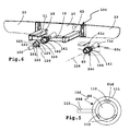
- a plug-in projection 140 of the fastening device 16c and a plug-in receptacle 121 of the holder 120 expediently have rectangular or square outer and inner contours, wherein other, also round geometries, are possible.
- the plug-in receptacle 121 is provided on a sleeve-like receiving part 122.
- an eccentric longitudinal stop 123 is provided on the receiving part 122.
- the longitudinal stop 123 and an abutment region or clamping region of the receiving part 122 are provided with a longitudinal spacing relative to one another with respect to a plug-in axis 124, which can advantageously bring about a certain tilting or tilting in the sense of optimized bracing.
- An abutment region 125 that is to say an abutment, is arranged or provided, for example, on a support sleeve 126, which in turn is arranged against rotation at the free end of the receiving part 122, for example welded or glued or screwed on.
- a support sleeve 126 which has a thread
- a holding member 61c forming cap sleeve 142 is screwed, which can be screwed onto the thread on the support sleeve 126.
- the two threads form form-fitting contours and counter-form-fitting contours.
- cap sleeve 142 is rotatable and displaceable to some extent with respect to the plug-in axis 124, which also represents a clamping axis, but only up to a not shown End stop. This makes it possible that by tightening the cap sleeve 142 on the support sleeve 126 of the mounting arm 141 is clamped to the vehicle bracket 13c.
- the holding member 61c i. the cap sleeve 142
- the holding member 61c is driven by a holding drive 60c.
- a drive pinion 143 of a motor 71c of the holding drive 60c meshes with a toothing 144 on the holding member 61c (the cap sleeve 142) so that it can be adjusted by a motor between a holding position screwed onto the supporting sleeve 126 and a release position.
- the fastening device 16c can be switched on and off via a drive switch 42.
- the fastening device 16c can be connected to an electrical system of the vehicle 80 via an electrical connection (not shown), e.g. for their control and / or electrical power supply.
- electrical contacts are present in the interior of the plug-in receptacle 121 and on the plug-in projection 140, which come into contact when the two parts are pushed against each other.
- the fastener 16c disposed on the load carrier 10c could equally be provided on the vehicle 80 and the "passive" component, i. e.g. the bracket 120, on the load carrier 10c. Then, for example, a support region similar to the support sleeve 126 may be provided on the insertion projection 140, while the movable support member, corresponding to the cap sleeve, in the region of. Plug receptacle 121 is arranged, wherein there, on the vehicle, then also conveniently the holding drive is provided.
- a holding drive 160 arranged on the vehicle 80, which can move a tie rod 161 back and forth in the direction of the plug axis 124 and / or pivot transversely thereto, wherein the tie rod 161 forms a holding member and into a plug projection 140 provided, ie provided on the load-carrier-side component of the load carrier coupling receptacle, so a resistance, and thus engages the two coupling parts (plug 121 and plug 140) against each other can clamp.
Landscapes
- Engineering & Computer Science (AREA)
- Mechanical Engineering (AREA)
- Fittings On The Vehicle Exterior For Carrying Loads, And Devices For Holding Or Mounting Articles (AREA)
- Lock And Its Accessories (AREA)
- Agricultural Machines (AREA)
Abstract
Description
Die Erfindung betrifft einen Lastenträger für ein Fahrzeug, insbesondere einen Personenkraftwagen, mit einer Tragbasis zum Tragen einer Last, und mit einer Befestigungseinrichtung zum lösbaren Befestigen an einem Widerhalt, insbesondere einer Anhängekupplung, des Kraftfahrzeugs, wobei die Befestigungseinrichtung mindestens ein Halteglied aufweist, das zwischen einer zum Halten an dem Widerhalt vorgesehenen Haltestellung, und einer zum Entfernen der Befestigungseinrichtung von dem Widerhalt vorgesehenen Freigabestellung verstellbar istThe invention relates to a load carrier for a vehicle, in particular a passenger car, with a support base for carrying a load, and with a fastening means for releasably attaching to a support, in particular a trailer hitch of the motor vehicle, wherein the fastening means comprises at least one holding member which is between a for holding stop provided on the abutment, and a release position provided for removing the fastening device from the abutment is adjustable
Lastenträger, die an einem Heck eines Kraftfahrzeuges lösbar befestigbar sind, beispielsweise in eine Steckaufnahme einsteckbar oder an einer Anhängekupplung befestigbar sind, sind allgemein bekannt. Bei Nichtgebrauch können die Lastenträger vom Fahrzeug entfernt werden, so dass für die Beförderung des Lastenträgers am Fahrzeug kein Bauraum notwendig ist und zudem auch Gewicht eingespart wird, was den Kraftstoffverbrauch senkt.Load carriers, which are releasably attachable to a rear of a motor vehicle, for example, plugged into a plug-in receptacle or attachable to a trailer hitch, are well known. When not in use, the load carrier can be removed from the vehicle, so that no space is required for the carriage of the load carrier on the vehicle and also weight is saved, which reduces fuel consumption.
Zur Befestigung derartiger Lastenträger sind verschiedenartige Konzepte bekannt. Beispielsweise geht eine Lastenträger-Kupplung, also eine Befestigungseinrichtung im Sinne des Oberbegriffes des Anspruches 1, aus der
Es ist daher die Aufgabe der vorliegenden Erfindung, einen bequem handhabbaren Lastenträger bereitzustellen.It is therefore the object of the present invention to provide a conveniently handleable load carrier.
Zur Lösung der Aufgabe ist bei einem Lastenträger der eingangs genannten Art vorgesehen, dass die Befestigungseinrichtung mindestens einen mit einem Antriebsschalter schaltbaren elektrischen oder fluidischen Halteantrieb zum Antreiben des mindestens einen Halteglieds aufweist.To solve the problem is provided in a load carrier of the type mentioned that the fastening device has at least one switchable with a drive switch electrical or fluidic holding drive for driving the at least one holding member.
Die Erfindung betrifft ferner eine Lastenträger-Kupplung oder eine Befestigungseinrichtung für einen Lastenträger. Die Befestigungseinrichtung kann die unten beschriebenen Antriebsschalter, Sensoren, eine Steuerung oder dergleichen umfassen und vorzugsweise als ein Modul ausgestaltet sein, das an einem Lastenträger oder einem Fahrzeug befestigt werden kann.The invention further relates to a load carrier coupling or a fastening device for a load carrier. The attachment means may comprise the drive switches, sensors, a controller or the like described below, and preferably be configured as a module which may be attached to a load carrier or a vehicle.
Der erfindungsgemäße Gedanke ist es also, dass ein motorischer Antrieb, also ein Halteantrieb mit Motor, zum Antreiben des einen Halteglieds oder mehrerer Halteglieder vorhanden ist. Eine manuelle Betätigung wäre zwar prinzipiell möglich, beispielsweise als Notbetätigung, wobei dies vorteilhaft nur eine zusätzliche, optionale Maßnahme darstellt.The idea according to the invention is thus that a motor drive, that is to say a holding drive with motor, is present for driving the one or more holding members. Although manual operation would be possible in principle, for example as an emergency operation, this advantageously represents only an additional, optional measure.
Bei der Befestigungseinrichtung ist vorgesehen, dass beispielsweise der Antriebsmotor am Lastenträger, d.h. am vom Kraftfahrzeug entfernbaren Bauteil angeordnet ist. Es ist aber auch möglich, dass ein Halteantrieb der Befestigungseinrichtung fahrzeugseitig montiert ist, d.h. also am Fahrzeug verbleibt, während der Lastenträger sozusagen das passive Bauteil darstellt. Selbstverständlich ist es auch möglich, dass an beiden Teilen, nämlich am Fahrzeug und am Lastenträger jeweils mindestens ein Halteantrieb der Befestigungseinrichtung vorgesehen ist.In the fastening device is provided that, for example, the drive motor on the load carrier, that is arranged on the component removable from the motor vehicle. But it is also possible that a holding drive of the fastening device is mounted on the vehicle side, that is, so remains on the vehicle, while the load carrier is, so to speak, the passive component. Of course, it is also possible that in each case at least one holding drive of the fastening device is provided on both parts, namely on the vehicle and on the load carrier.
Sämtliche nachfolgend im Zusammenhang mit dem Lastenträger beschriebenen Maßnahmen können selbstverständlich auch bei der erfindungsgemäßen Lastenträgerkupplung vorgesehen sein, so zum Beispiel dass das Halteglied durch Federkraft in die Freigabestellung oder die Haltestellung vorgespannt ist, dass der Halteantrieb mehrfach bestromt wird, um die Haltekraft immer wieder neu zu vergrößern oder dergleichen. Auch das Steuerungskonzept, das nachfolgend noch erläutert wird, ist selbstverständlich bei der Lastenträgerkupplung unabhängig davon realisierbar, ob ein jeweiliger Halteantrieb am vom Fahrzeug lösbaren Bauteil, dem Lastenträger, oder am Fahrzeug vorgesehen ist.All measures described below in connection with the load carrier can of course also be provided in the load carrier coupling according to the invention, for example, that the holding member is biased by spring force into the release position or the holding position that the holding drive is energized several times to the holding force again and again enlarge or the like. The control concept, which will be explained below, is of course also feasible in the load carrier coupling regardless of whether a respective holding drive is provided on the vehicle-detachable component, the load carrier, or on the vehicle.
Es versteht sich, dass das Konzept gemäß der Erfindung sowohl bei an einer Anhängekupplung befestigbaren Befestigungseinrichtungen oder damit ausgestatteten Lastenträgern zum Einsatz kommen kann, aber auch bei einer Lastenträgerkupplung oder einer Befestigungseinrichtung, die beispielsweise an einer Halterung des Fahrzeuges montiert, z.B. an eine Steckaufnahme oder an eine Steckaufnahmenanordnung angesteckt oder auf Steckvorsprünge am Fahrzeug aufgesteckt, werden kann. Mithin kann also die Befestigung, insbesondere die Verriegelung und Verklemmung, auch bei solchen Heckträgern motorisch geschehen. Weiterhin ist es im Sinne der Erfindung, dass nicht nur am Lastenträger selbst der Antrieb vorhanden sein kann, sondern auch beispielsweise an der fahrzeugseitigen Halterung oder Befestigungskomponente, beispielsweise einer Steckaufnahme. Die fahrzeugseitige Halterung kann mit einem Halteglied versehen sein, das erfindungsgemäß motorisch antreibbar ist.It will be appreciated that the concept according to the invention can be used both with attachment devices fastened to a trailer hitch or with load carriers equipped therewith, but also with a load carrier coupling or a fastening device mounted, for example, on a mounting of the vehicle, e.g. can be plugged into a plug-in receptacle or a plug-in receptacle assembly or attached to plug-in projections on the vehicle. Thus, therefore, the attachment, in particular the locking and jamming, done motorized even with such rear carriers. Furthermore, it is within the meaning of the invention that not only on the load carrier itself, the drive can be present, but also for example on the vehicle-mounted bracket or mounting component, such as a plug-in receptacle. The vehicle-mounted bracket may be provided with a holding member which is motor driven according to the invention.
Das mindestens eine Halteglied ist zweckmäßigerweise durch eine Federanordnung in die Haltestellung oder die Freigabestellung belastet. Somit wirkt der Halteantrieb beispielsweise entgegen der Kraft der Federanordnung im Sinne beispielsweise eines Lösens der Halteeinrichtung oder der Befestigungseinrichtung. Eine Federanordnung stellt insbesondere bei einer Störung oder einem Ausfall des Halteantriebs eine Sicherheit dar. Der Halteantrieb muss nur beim Montieren oder Demontieren der Befestigungseinrichtung betätigt werden bzw. auf das Halteglied wirken.The at least one holding member is expediently loaded by a spring arrangement in the holding position or the release position. Thus, the holding drive, for example, counteracts the force of the spring arrangement in the sense of, for example, a release the holding device or the fastening device. A spring arrangement represents a security, in particular in the event of a fault or failure of the holding drive. The holding drive only has to be actuated or mounted on the holding member when mounting or dismounting the fastening device.
Es versteht sich, dass das Halteglied bei einer erfindungsgemäßen Lastenträger-Kupplung bzw. bei einem erfindungsgemäßen Lastenträger beispielsweise auch einen Zuganker, Haken oder dergleichen umfassen kann, der motorisch angetrieben wird.It is understood that the holding member in a load carrier coupling according to the invention or in a load carrier according to the invention may for example also include a tie rod, hook or the like, which is driven by a motor.
Bevorzugt ist es, dass das Halteglied ein Formschlussglied umfasst, insbesondere einen Klemmkörper. Der Widerhalt, beispielsweise ein Kuppelkörper, der kugelig sein oder auch eine sonstige Geometrie aufweisen kann, ist dann zwischen den Klemmkörper und den Widerlagerkörper klemmbar. Beispielsweise kann der Kuppelkörper einen Bestandteil einer Anhängekupplung bilden. Bevorzugt ist als Kuppelkörper eine Kupplungskugel, das heißt ein kugeliger Widerhalt.It is preferred that the holding member comprises a form-fitting element, in particular a clamping body. The abutment, for example, a dome body, which may be spherical or may have a different geometry is then clamped between the clamping body and the abutment body. For example, the dome body may form part of a hitch. Preferably, as a coupling body, a coupling ball, that is a spherical Widerhalt.
Der Klemmkörper und der Widerlagerkörper sind zweckmäßigerweise also zum Klemmen einer Kupplungskugel ausgestaltet. Bevorzugt ist eine Klemmung im Äquatorialbereich. Weiterhin ist es vorteilhaft, wenn die Befestigungseinrichtung eine Stütze aufweist, mit der sie sich unmittelbar am Kuppelkörper, insbesondere der Kupplungskugel abstützen kann. Bevorzugt ist die Stütze so ausgestaltet und/oder angeordnet, dass sie sich oben an der bei einer Normkupplungskugel vorhandenen Abflachung abstützen kann. Somit ist ein einfaches Ausrichten des Lastenträgers bzw. der Befestigungseinrichtung an der ansonsten kugeligen Klemmfläche möglich.The clamping body and the abutment body are thus expediently designed for clamping a coupling ball. A clamping in the equatorial region is preferred. Furthermore, it is advantageous if the fastening device has a support, with which it can be supported directly on the coupling body, in particular the coupling ball. Preferably, the support is designed and / or arranged so that it can be supported at the top of the flattening present in a standard coupling ball. Thus, a simple alignment of the load carrier or the fastening device on the otherwise spherical clamping surface is possible.
Der Antriebsschalter kann beispielsweise ein Tastschalter sein. Bevorzugt umfasst der Antriebsschalter nicht nur einen, sondern mehrere Schalter. Beispielsweise kann ein Bediener einen Druckschalter betätigen, der dann als Antriebsschalter wirkt. Allerdings ist es z.B. aus Gründen der Sicherheit oder des Komforts möglich, dass mehrere Antriebsschalter, z.B. Bediener-Antriebsschalter und/oder Sensoren, betätigt sein müssen oder ein entsprechendes Betätigungssignal ausgeben müssen, um den Halteantrieb zu schalten.The drive switch may be, for example, a push button. Preferably, the drive switch comprises not only one, but several switches. For example, an operator can actuate a pressure switch, which then acts as a drive switch. However, it is possible for reasons of safety or comfort, for example, that several drive switches, eg operator drive switches and / or sensors, must be actuated or have to output a corresponding actuation signal in order to switch the holding drive.
Der Antriebsschalter kann aber auch ein Sensor sein oder einen Sensor umfassen, beispielsweise ein Abstandsensor, ein optischer Sensor oder dergleichen. Selbstverständlich können auch mehrere derartige Sensoren vorhanden sein. Bevorzugt umfasst der Antriebsschalter nämlich mindestens einen durch den Widerhalt betätigbaren Sensor, beispielsweise zwei oder mehr Sensoren, die einen Abstand zum Widerhalt, z.B. dem Kuppelkörper oder einer Steckaufnahme oder einem Steckvorsprung, messen können. Somit ist der Halteantrieb in Abhängigkeit von einem Abstand des jeweiligen Sensors von dem Widerhalt schaltbar.The drive switch may also be a sensor or comprise a sensor, for example a distance sensor, an optical sensor or the like. Of course, several such sensors may be present. Namely, the drive switch preferably comprises at least one sensor operable by the resistor, for example two or more sensors which are at a distance from the resistor, e.g. the dome body or a plug-in receptacle or a plug-in projection, can measure. Thus, the holding drive is switchable in dependence on a distance of the respective sensor of the abutment.
Eine solche Sensoranordnung, die beispielsweise zwei oder mehr Sensoren umfasst, kann auch zur Ausrichtung der Befestigungseinrichtung am Kuppelkörper bzw. am Widerhalt genutzt werden. Wenn beispielsweise die als Antriebsschalter wirkenden oder mit dem Antriebsschalter zusammenwirkenden Sensoren denselben oder einen jeweils vorbestimmten Abstand zum Widerhalt messen, also z.B. eine Parallelität beispielsweise zur Abflachung an der Oberseite der Normkupplungskugel vorhanden ist, wird der Halteantrieb in Richtung seiner Haltestellung betätigt. Ist dies nicht der Fall, das heißt dass die Befestigungseinrichtung eine Schräglage einnimmt, messen dies die Sensoren und schalten den Halteantrieb ab.Such a sensor arrangement, which comprises, for example, two or more sensors, can also be used for aligning the fastening device on the dome body or on the abutment. For example, if the sensors acting as drive switches or cooperating with the drive switch measure the same or a predetermined distance to the resistor, e.g. a parallelism, for example, to the flattening at the top of the standard coupling ball is present, the holding drive is actuated in the direction of its holding position. If this is not the case, that is to say that the fastening device assumes an inclined position, the sensors measure this and switch off the holding drive.
Weiterhin ist es zweckmäßig, dass der Antriebsschalter beispielsweise auch einen oder mehrere Bedienersensoren umfasst, beispielsweise Abstandssensoren, optische Sensoren oder dergleichen. Der mindestens eine Bedienersensor kann beispielsweise den Bediener selbst oder eine Bedienhandlung eines Bedieners erfassen. Wenn sich also beispielsweise ein Bediener im Nahbereich des Lastenträgers befindet, diesen also z.B. stützt oder hält, wird dadurch der Halteantrieb beispielsweise schaltbar oder geschaltet. Es ist auch möglich, dass der Bediener eine vorbestimmte Bedienhandlung an dem Abstandssensor vornimmt, beispielsweise seine Hand vor diesem schwenkt, um somit den Halteantrieb einzuschalten.Furthermore, it is expedient that the drive switch also comprises, for example, one or more operator sensors, For example, distance sensors, optical sensors or the like. The at least one operator sensor can detect, for example, the operator himself or an operator's action. If, for example, an operator is in the vicinity of the load carrier, that is, for example, supports or holds it, the holding drive is thereby for example switched or switched. It is also possible that the operator makes a predetermined operation on the distance sensor, for example, his hand pivots in front of this, so as to turn on the holding drive.
Der Halteantrieb kann zweckmäßigerweise ein Spanngetriebe aufweisen oder auch ein Klemmgetriebe. Es ist also möglich, dass zwischen dem Halteglied und dem Halteantrieb ein Spanngetriebe und/oder Klemmgetriebe vorhanden ist. Das Getriebe ist vorzugsweise ein Übersetzungsgetriebe, so dass die Kraft des Halteantriebs bzw. eines Motors des Halteantriebs verstärkt wird, wenn sich dieser bewegt.The holding drive may expediently have a tensioning gear or a clamping gear. It is therefore possible that a clamping gear and / or clamping gear is present between the holding member and the holding drive. The transmission is preferably a transmission gear, so that the force of the holding drive or a motor of the holding drive is amplified when it moves.
Selbstverständlich kann der Halteantrieb ein Drehantrieb sein oder auch ein Linearantrieb.Of course, the holding drive may be a rotary drive or a linear drive.
Weiterhin ist es möglich, dass zwischen dem Halteantrieb-Motor und dem Halteglied beispielsweise auch ein Seilzug vorhanden ist. Selbstverständlich könnte auch eine Zahnriemenanordnung vorgesehen sein. Mithin kann also ein Übertragungsgetriebe zwischen dem Motor des Halteantriebs und dem Halteglied vorhanden sein, so dass eine größere Entfernung zwischen dem Motor des Halteantriebs und dem Halteglied möglich ist. Das Übertragungsgetriebe kann beispielsweise eine Stange, einen Seilzug, einen Bowdenzug oder dergleichen umfassen.Furthermore, it is possible that between the holding drive motor and the support member, for example, a cable is present. Of course, a toothed belt arrangement could also be provided. Thus, therefore, a transmission gear between the motor of the holding drive and the holding member may be present, so that a greater distance between the motor of the holding drive and the holding member is possible. The transmission gear may include, for example, a rod, a cable, a Bowden cable or the like.
Das Halteglied kann in einer bevorzugten Ausführungsform einen Riegel umfassen. Die Befestigungseinrichtung könnte man dann auch als Verriegelungseinrichtung bezeichnen. Es versteht sich, dass auch mehrere Riegel vorgesehen sein können.The holding member may comprise a latch in a preferred embodiment. The attachment device could then one Also refer to as a locking device. It is understood that several bars can be provided.
Eine weitere Variante der Erfindung sieht vor, dass das Halteglied ein Formschlussglied umfasst, das zu einem Formschluss mit einer Formschlussgegenkontur am Widerhalt, z.B. einem Kuppelkörper oder einer Kupplungskugel, einer Steckaufnahme oder dergleichen, ausgestaltet ist. Wenn das Formschlussglied formschlüssig in die Formschlussgegenkontur eingreift bzw. mit dieser in formschlüssigem Eingriff ist, wird dadurch der Halt Befestigungseinrichtung am Widerhalt bewirkt.A further variant of the invention provides that the holding member comprises a form-fitting member, which for a positive connection with a form-fitting counter contour on the abutment, e.g. a coupling body or a coupling ball, a plug-in receptacle or the like, is configured. If the form-fitting element engages positively in the form-fitting counter-contour or is in positive engagement with the latter, this causes the fastening device to be held on the abutment.
Aber auch ein Verklemmen oder Verspannen des Lastenträgers am Widerhalt ist möglich, so dass dieser bezüglich des Fahrzeugs verspannt bzw. verklemmt ist. In diesem Fall umfasst das Halteglied beispielsweise ein Spannelement.But jamming or distortion of the load carrier on the abutment is possible, so that it is clamped or jammed with respect to the vehicle. In this case, the holding member comprises, for example, a clamping element.
Ein weiterer innovativer Gedanke, sieht vor, dass das Halteglied sowohl zum Verriegeln, als auch zum Spannen und/oder Klemmen ausgestaltet ist. Beispielsweise hat das Halteglied in dieser Ausgestaltung der Erfindung eine Riegelfläche und eine Spannfläche und/oder Klemmfläche. Die Riegelfläche oder die Spannfläche sind bezogen auf die Verriegelungsbewegung oder Entriegelungsbewegung des mindestens einen Halteglieds benachbart zueinander, z.B. nebeneinander angeordnet. Sie wirken mit einer Verriegelungsgegenkontur und einer Klemmgegenkontur bzw. Spanngegenkontur zusammen. Bei der Verriegelungsbewegung läuft die Kinematik nun so ab, dass zunächst die Riegelfläche und die Verriegelungsgegenkontur in Eingriff miteinander gelangen oder zumindest nebeneinander angeordnet sind, dann erst die Spannfläche mit der Spanngegenkontur oder die Klemmfläche mit der Klemmgegenkontur in Eingriff gelangen. Somit kann also das Halteglied zunächst eine Verriegelung des Lastenträgers und anschließend eine Verklemmung bewirken. Somit ist ein "klapperfreier" Fahrbetrieb möglich.Another innovative idea, provides that the holding member is designed both for locking, as well as for clamping and / or clamping. For example, the retaining member in this embodiment of the invention has a locking surface and a clamping surface and / or clamping surface. The locking surface or the clamping surface are related to the locking movement or unlocking movement of the at least one holding member adjacent to each other, for example, arranged side by side. They cooperate with a locking counter contour and a clamping counter contour or clamping counter contour. During the locking movement, the kinematics now run so that initially the locking surface and the locking counter contour come into engagement with each other or at least next to each other, then only the clamping surface with the clamping counter contour or the clamping surface with the clamping counter contour engage. Thus, therefore, the holding member is first a lock of the load carrier and then cause a deadlock. Thus, a "rattle-free" driving is possible.
Das Entriegeln bzw. Entspannen verläuft sinngemäß umgekehrt, so dass das Halteglied zunächst die Verspannung oder Verklemmung aufhebt, anschließend die Verriegelung.Unlocking or relaxing is analogously reversed, so that the holding member first lifts the tension or jamming, then the lock.
Bevorzugt ist eine Steuerung für den Halteantrieb vorgesehen.Preferably, a control for the holding drive is provided.
Die Steuerung kann beispielsweise so ausgestaltet sein, dass sie den Halteantrieb periodisch wiederholt mit Energie versorgt, beispielsweise bestromt oder fluidtechnisch ansteuert, wobei diese Energieversorgung von einer vorigen Betätigung durch den Antriebsschalter abhängt. Wird also der Halteantrieb durch den Antriebsschalter in Richtung der Haltestellung betätigt, taktet die Steuerung sozusagen nach und beaufschlagt den Halteantrieb immer wieder in Richtung der Haltestellung. Dadurch wird einem unbeabsichtigten Lösen des Halteglieds vorgebeugt. Auch das umgekehrte ist möglich, dass nämlich die Steuerung den Halteantrieb in Richtung der Freigabestellung periodisch mit Energie versorgt, wenn zuvor von einem Bediener der Befehl zum Schalten in Richtung der Freigabestellung gegeben worden ist.The controller may be configured, for example, so that it repeatedly periodically supplies the holding drive with energy, for example energized or fluidly actuated, wherein this power supply depends on a previous actuation by the drive switch. Thus, if the holding drive is actuated by the drive switch in the direction of the holding position, the controller clocks, as it were, and acts on the holding drive repeatedly in the direction of the holding position. As a result, an unintentional release of the holding member is prevented. The reverse is also possible, namely that the controller periodically supplies the holding drive in the direction of the release position with energy, if previously given by an operator command to switch in the direction of the release position.
Bevorzugt ist es, wenn der Lastenträger einen Empfänger zur drahtlosen Ansteuerung des Antriebsschalters aufweist. Somit kann also der Antriebsschalter drahtlos angesteuert werden, z.B. mit einer Fernbedienung, die ansonsten zur Verriegelung oder zum Öffnen des Fahrzeuges (Zentralverriegelung) vorgesehen ist.It is preferred if the load carrier has a receiver for wireless control of the drive switch. Thus, therefore, the drive switch can be wirelessly controlled, e.g. with a remote control, which is otherwise intended for locking or to open the vehicle (central locking).
Bevorzugt hat der Empfänger einen sehr kurzen, begrenzten Empfangsbereich. Dieser kann beispielsweise nur 50 bis 200cm betragen. Bevorzugt ist der Empfänger zur Anordnung am Heck des Kraftfahrzeuges ausgestaltet bzw. vorgesehen. Alle vorgenannten Maßnahmen haben den Vorteil, dass die Befestigungseinrichtung nur dann in die Freigabestellung verstellt werden kann, wenn sich ein Bediener in der Nähe des Lastenträgers befindet. Auch dies hat den Vorteil, dass der Lastenträger nicht unkontrolliert vom Fahrzeug entfernt werden kann, unter anderem als Diebstahlsicherung.Preferably, the receiver has a very short, limited reception area. This can for example be only 50 to 200cm. Preferably, the receiver is designed or provided for arrangement at the rear of the motor vehicle. All the above measures have the advantage that the fastening device can only be moved to the release position when an operator is in the vicinity of the load carrier. This also has the advantage that the load carrier can not be removed unchecked from the vehicle, including as anti-theft device.
Der Lastenträger hat zweckmäßigerweise eine Steuerung zur Aktivschaltung und/oder Deaktivierung des Halteantriebs oder auch des mindestens einen Antriebsschalters anhand mindestens einer Aktivierungsbedingung, die man im Falle der Deaktivierung auch als Deaktivierungsbedingung bezeichnen kann.The load carrier expediently has a control for activating and / or deactivating the holding drive or also the at least one drive switch on the basis of at least one activation condition, which in the case of deactivation can also be referred to as a deactivation condition.
Die Steuerung kann so ausgestaltet sein, dass sie den Antriebsschalter oder den Halteantrieb anhand der mindestens einen Aktivierungsbedingung für ein Zeitintervall aktiv schaltet oder deaktiviert. Somit ist es beispielsweise nur während dieses aktiven Zeitintervalles möglich, dass ein Bediener den Antriebsschalter betätigt, der beispielsweise im Heckbereich des Fahrzeuges oder am Lastenträger angeordnet ist.The controller may be configured to actively switch or disable the drive switch or the hold drive based on the at least one activation condition for a time interval. Thus, for example, it is possible only during this active time interval for an operator to actuate the drive switch, which is arranged, for example, in the rear region of the vehicle or on the load carrier.
Der Lastenträger ist zweckmäßigerweise über elektrische Kontakte mit einem Bordnetz des Fahrzeugs verbindbar, z.B. zur Stromversorgung und/oder zu Steuerungszwecken. Beispielsweise hat der Lastenträger einen Stecker zum Einstecken in eine Anhängersteckdose. Vorzugsweise hat der Lastenträger einen Buskoppler zum Empfangen von Bussignalen von dem Bordnetz.The load carrier is suitably connectable via electrical contacts with an electrical system of the vehicle, e.g. for power supply and / or for control purposes. For example, the load carrier has a plug for plugging in a trailer socket. Preferably, the load carrier has a bus coupler for receiving bus signals from the electrical system.
Vorzugsweise umfasst die Steuerung zur Betätigung des elektrischen Antriebsschalters ein Betätigungselement mit einem in einem Außenbereich des Fahrzeugs angeordneten Bedienbereich nahe bei dem Lastenträger oder am Lastenträger selbst, insbesondere in einem zum Ergreifen des Lastenträgers vorgesehenen Griffbereich. Somit ist das Betätigungselement am oder nahe beim Lastenträger bedienbar, so dass der Bediener beispielsweise gleichzeitig den Lastenträger ergreifen und den Antriebsschalter betätigen kann.The control for actuating the electric drive switch preferably comprises an actuating element with an operating region arranged in an outer region of the vehicle close to the load carrier or on the load carrier itself, in particular in a gripping region provided for gripping the load carrier. Thus, the actuator is operable on or near the load carrier, so that the operator, for example at the same time can grab the load carrier and operate the drive switch.
Die Steuerung umfasst weiterhin zweckmäßigerweise einen Sensoreingang und/oder einen Sensor und ist zur Auswertung eines Sensorsignals des Sensors als Aktivierungsbedingung ausgeschaltet, z.B. eines der vorher erläuterten Abstandssensoren.The controller expediently comprises a sensor input and / or a sensor and is switched off to evaluate a sensor signal of the sensor as an activation condition, e.g. one of the previously explained distance sensors.
Eine weitere Aktivierungsbedingung, die der Lastenträger über das Bordnetz des Fahrzeugs empfangen kann, kann auch der Stillstand eines Fahrzeug-Motors des Fahrzeugs sein, so dass beispielsweise bei laufendem Motor ein Betätigen des Halteantriebes nicht möglich ist.Another activation condition that can be received by the load carrier via the electrical system of the vehicle, the standstill of a vehicle engine of the vehicle may also be, so that, for example, when the engine is running, an actuation of the holding drive is not possible.
Weitere Aktivierungsbedingungen können sein:
- Eine Zentralverriegelung des Kraftfahrzeuges signalisiert "Fahrzeugtüren entriegelt"
- Schlüssel ist aus dem Zündschloss des Kraftfahrzeuges entfernt
- Motor ist aus, beispielsweise Klemme 15 aus,
- Klemme 15 ein, Kraftfahrzeug ist betriebsbereit
- oder eine sonstige Stellung des Motorstartschalters.
- A central locking of the motor vehicle signals "unlocked vehicle doors"
- Key is removed from the ignition of the vehicle
- Engine is off, for example terminal 15 off,
- Terminal 15 on, motor vehicle is ready for use
- or another position of the engine start switch.
Eine vorteilhafte Ausgestaltung der Erfindung sieht vor, dass die mindestens eine Aktivierungsbedingung ein von einem Freigabeschalter sendbares Freigabesignal ist oder umfasst. Der Freigabeschalter ist beispielsweise im Innenraum des Fahrzeugs, beispielsweise im Cockpit desselben, im Gepäckabteil, vorzugsweise geschützt durch einen Deckel, oder an anderer Stelle des Fahrzeuges angeordnet. Der Freigabeschalter kann aber auch einen an einem Fahrzeugschlüssel für das Fahrzeug oder an einem am Schlüsselanhängergehäuse angeordneten Sender umfassen und der Lastenträger einen zugeordneten Funkempfänger zum Empfang des Freigabesignals.An advantageous embodiment of the invention provides that the at least one activation condition is or includes a release signal that can be sent by a release switch. The release switch is arranged, for example, in the interior of the vehicle, for example in the cockpit thereof, in the luggage compartment, preferably protected by a cover, or elsewhere in the vehicle. However, the release switch can also comprise a transmitter arranged on a vehicle key for the vehicle or on a key fob housing and the load carrier an associated radio receiver for receiving the release signal.
Somit kann beispielsweise durch Betätigung des Freigabeschalters im Schlüssel das Zeitintervall durch den Bediener des Fahrzeuges gegeben werden, worauf dann das Zeitintervall zur Betätigung des Antriebsschalters beginnt. Der Sender ist beispielsweise in einem Fahrzeugschlüsselgehäuse, insbesondere dessen Griff, angeordnet.Thus, for example, by operating the release switch in the key, the time interval can be given by the operator of the vehicle, whereupon the time interval for actuating the drive switch begins. The transmitter is arranged, for example, in a vehicle key housing, in particular its handle.
Die mindestens eine Aktivierungsbedingung kann auch eine Funktionsstellung eines Motorschalters zum Starten eines Fahrzeug-Motors des Fahrzeugs umfassen. Die Funktionsstellung ist beispielsweise eine Betriebsbereitschaft des Fahrzeuges, zum Beispiel ein Signal "Klemme 15 ein". Das Signal kann beispielsweise das geschaltete Plus am Zündstartschalter sein ("Klemme 15") oder auch die sogenannte Zündschloss-Radiostellung ("Klemme 15r").The at least one activation condition may also include a functional position of an engine switch for starting a vehicle engine of the vehicle. The functional position is for example an operational readiness of the vehicle, for example a signal "terminal 15 on". The signal may be, for example, the switched plus on the ignition start switch ("terminal 15") or else the so-called ignition lock radio position ("terminal 15r").
Es ist aber auch der gerade umgekehrte Fall möglich, dass nämlich die mindestens eine Aktivierungsbedingung eine Funktionsstellung "Motor aus", zum Beispiel "Klemme 15", des Motorstartschalters umfasst. Somit ist also eine der Aktivierungsbedingungen jedenfalls so getroffen, dass zu der Aktivierung des Antriebsschalters und/oder zum Auslösen des Zeitintervalls der Motor ausgeschaltet wird oder ist. Die Aktivierungsbedingung kann beispielsweise auch ein Zustandswechsel "Motor ein - Motor aus" sein, so dass beispielsweise nach Abstellen des Fahrzeuges die Befestigungseinrichtung betätigbar ist, z.B. in die Freigabestellung verstellbar ist und/oder das Zeitintervall zum Betätigen Lösen der Befestigungseinrichtung beginnt und der Bediener Lastenträger beispielsweise nach Betätigen des Antriebsschalters und Entriegeln der Befestigungseinrichtung verstellen oder entfernen kann. Ein Zeitintervall, innerhalb dessen die Befestigungseinrichtung betätigbar ist, ist in dieser Situation vorzugsweise so bemessen, dass der Bediener zwar bequem zum Heck des Fahrzeuges gehen und dort den Lastenträger bedienen kann. Dann endet das Zeitintervall jedoch, so dass eine Fehlmanipulation des Lastenträgers verhindert wird.However, the reverse case is also possible, namely that the at least one activation condition comprises a functional position "motor off", for example "terminal 15", of the motor start switch. Thus, therefore, one of the activation conditions is in any case made such that the motor is switched off or is to the activation of the drive switch and / or to trigger the time interval. The activation condition may be, for example, a state change "engine on - engine off", so that, for example, after stopping the vehicle, the fastening device is actuated, eg in the release position is adjustable and / or the time interval for actuating release of the fastening device begins and the operator load carrier, for example can adjust or remove after pressing the drive switch and unlocking the fastening device. In this situation, a time interval within which the fastening device can be actuated is preferably dimensioned so that the operator can comfortably walk to the rear of the vehicle and can serve there the load carrier. Then, however, the time interval ends so that erroneous manipulation of the load carrier is prevented.
Die mindestens eine Aktivierungsbedingung kann auch eine Bestromung einer Leuchte des Fahrzeugs, insbesondere einer am Heck des Fahrzeugs angeordneten Leuchte, und/oder eine am Lastenträger angeordnete Leuchte umfassen. Die Heckleuchte ist beispielsweise eine Nebelschlussleuchte, ein Rückfahrscheinwerfer, eine Blinkleuchte des Fahrzeugs oder des Lastenträgers oder dergleichen. Wenn die erfindungsgemäße Steuerung auf der Basis des Heckleuchtensignals arbeitet, sind nur kurze Kabelwege erforderlich, was z.B. kostengünstig ist.The at least one activation condition may also include an energization of a lamp of the vehicle, in particular a lamp arranged at the rear of the vehicle, and / or a lamp arranged on the load carrier. The tail light is, for example, a rear fog lamp, a reversing light, a flashing light of the vehicle or the load carrier or the like. When the control according to the invention operates on the basis of the tail light signal, only short cable runs are required, e.g. is inexpensive.
Eine Variante der Erfindung kann vorsehen, dass die Leuchte eine Leuchte des Lastenträgers ist, deren Bestromung eine Aktivierungsbedingung für die erfindungsgemäße Steuerung bildet. So könnte die Steuerung beispielsweise mit einer Stromversorgungsleitung für mindestens eine dieser lastenträgerseitigen Leuchten verbunden sein, beispielsweise mit der zum Lastenträger führenden Versorgungsleitung. Diese Variante ist aufgrund einer kurzen Leitungsführung vorteilhaft.A variant of the invention can provide that the luminaire is a luminaire of the load carrier whose energization constitutes an activation condition for the control according to the invention. For example, the controller could be connected to a power supply line for at least one of these load-carrier-side lights, for example with the supply line leading to the load carrier. This variant is advantageous due to a short cable routing.
Besonders bevorzugt ist jedoch, dass die Steuerung zur Ermittlung einer Bestromung der Leuchte mit einem Bordnetz des Fahrzeugs, zum Beispiel mit einer zur jeweiligen Leuchte führenden Stromversorgungsleitung, verbunden ist. Es ist aber auch möglich, dass die Steuerung mit einem Bus des Bordnetzes verbunden ist, über das die Leuchte aktiviert wird. Das Bordnetz des Fahrzeugs ist von außen nicht manipulierbar, was die Diebstahlsicherheit verbessert. Kontakte der Anhänger-Steckdose sind nämlich prinzipiell von außen her zugänglich und dementsprechend manipulierbar.However, it is particularly preferred that the control for determining an energization of the luminaire is connected to an electrical system of the vehicle, for example with a power supply line leading to the respective luminaire. But it is also possible that the controller is connected to a bus of the electrical system, via which the light is activated. The electrical system of the vehicle can not be manipulated from the outside, which improves theft security. Contacts of the trailer socket are in principle accessible from the outside and accordingly manipulated.
Die mindestens eine Aktivierungsbedingung bildet zweckmäßigerweise einen Bestandteil einer Aktivierungsbedingungsgruppe, die die Steuerung zur Aktivschaltung des Antriebsschalters für das Zeitintervall prüft, wobei die Aktivierungsbedingungsgruppe mindestens zwei Aktivierungsbedingungen aufweist, welche die Steuerung für eine Aktivierung des Antriebsschalters prüft. Somit ist eine Aktivierung des Antriebsschalters bei einem Einfachfehler, beispielsweise einem Kurzschluss, einer Störung an einem Schalter, durch eine Manipulation von außen oder dergleichen, unproblematisch, weil mindestens eine zweite Aktivierungsbedingung hinzutreten muss, bevor die Steuerung den Antriebsschalter aktiv schaltet beziehungsweise für ein Auslösen des Halteantriebs freigibt.The at least one activation condition suitably forms part of an activation condition group which checks the control for activating the drive switch for the time interval, the activation condition group having at least two activation conditions which the control checks for activation of the drive switch. Thus, an activation of the drive switch in a single fault, such as a short circuit, a fault on a switch, by a manipulation from the outside or the like, unproblematic, because at least a second activation condition must occur before the controller activates the drive switch or for triggering the Holding drive releases.
Die Aktivierungsbedingungsgruppe umfasst zweckmäßigerweise mindestens zwei der vorgenannten Aktivierungsbedingungen.The activation condition group expediently comprises at least two of the aforementioned activation conditions.
Besonders vorteilhafte Varianten von Aktivierungsbedingungsgruppen werden nachfolgend vorgestellt:Particularly advantageous variants of activation condition groups are presented below:
Eine besonders bevorzugte Aktivierungsbedingungsgruppe umfasst beispielsweise die beiden folgenden Aktivierungsbedingungen: Motorstartschalter zum Starten eines Fahrzeug-Motors des Fahrzeugs in Funktionsstellung "Motor aus" und/oder "Schlüssel aus einem Zündschloss des Fahrzeugs entfernt". An dieser Bedingung erkennt die Steuerung, dass das Fahrzeug außer Betrieb ist. Eine andere Bedingung wäre, dass der Motor des Fahrzeuges nicht läuft. Allerdings ist das Signal "Klemme 15" im Bereich des Fahrzeug-Hecks z.B. wegen einer Anhänger-Steckdose beziehungsweise einer Anhängekupplung häufig ohnehin vorhanden, so dass die Stellung des Motorstartschalters eine bevorzugte, einfach realisierbare Bedingung ist. Die weitere Bedingung der Aktivierungsbedingungsgruppe ist dann:
- mindestens eine, vorzugsweise mindestens zwei Blinkleuchten des Fahrzeugs eingeschaltet beziehungsweise mit wechselnder Bestromung.
- at least one, preferably at least two flashing lights of the vehicle switched on or with alternating current.
Nach dem Abstellen des Fahrzeuges ist das Signal "Klemme 15" in der Regel "AUS" beziehungsweise wird der Zündschlüssel aus dem Zündschloss entfernt.After switching off the vehicle, the signal "terminal 15" is usually "OFF" or the ignition key is removed from the ignition.
In einem nächsten Schritt wird das Fahrzeug verriegelt oder entriegelt, wobei bei aktuellen Fahrzeugen die Blinker des Fahrzeuges zumindest einmal aufleuchten. Die Bedienung erfolgt beispielsweise über die Funkfernbedienung, deren Sender zweckmäßigerweise in einem Gehäuse des Fahrzeugschlüssels angeordnet ist. Die Sicherheit bei diesem Konzept ist hoch, da zum einen die Startbedingung "Klemme 15 aus" und zum anderen mindestens ein Heckleuchtensignal, vorzugsweise zwei Heckleuchtensignale (der beiden heckseitigen Blinkleuchten), von der erfindungsgemäßen Steuerung ausgewertet werden. Die Signale der heckseitigen Blinkerleuchten sind im Heckbereich mit kurzen Leitungswegen für die erfindungsgemäße Steuerung verfügbar. Eine Auslösung während der Fahrt des Fahrzeuges ist nicht möglich. Eine Sabotage ist kaum möglich. Zudem sind die Kosten dieser Variante gering. Die Bedienung ist komfortabel.In a next step, the vehicle is locked or unlocked, with current vehicles flashing the lights of the vehicle at least once. The operation takes place, for example, via the radio remote control, the transmitter is expediently arranged in a housing of the vehicle key. The safety in this concept is high because, on the one hand, the start condition "terminal 15 off" and, on the other hand, at least one tail light signal, preferably two tail light signals (the two rear turn signals), are evaluated by the controller according to the invention. The signals of the rear turn signals are available in the rear area with short cable routes for the control according to the invention. A trip while driving the vehicle is not possible. Sabotage is hardly possible. In addition, the cost of this variant are low. The operation is comfortable.
Es versteht sich, dass das Sicherheitskonzept der Aktivierungsbedingungsgruppe auch mit anderen kombinierten Aktivierungsbedingungen realisierbar ist, beispielsweise:
- Nebenschlussleuchte und/oder Rückfahrscheinwerfer eingeschaltet und
- Motorschalter zum Starten eines Fahrzeug-Motors des Fahrzeugs in Betriebsbereitschaft, beispielsweise Signal "Klemme 15 ein", "Schlüssel ins Zündschloss gesteckt" oder dergleichen.
- Shunt light and / or reversing lights switched on and
- Motor switch for starting a vehicle engine of the vehicle in operational readiness, for example, signal "terminal 15 on", "key inserted into the ignition" or the like.
Es versteht sich, dass zu den beiden vorgenannten Aktivierungsbedingungsgruppen auch weitere Aktivierungsbedingungen hinzutreten können, was die Sicherheit des erfindungsgemäßen Konzeptes erhöht.It is understood that to the two aforementioned activation conditions groups also further activation conditions can occur, which increases the security of the inventive concept.
Nachfolgend werden weitere Aktivierungsbedingungen erörtert, die vorteilhaft sind.In the following, further activation conditions will be discussed, which are advantageous.
Mindestens eine Aktivierungsbedingung kann beispielsweise auch umfassen, dass der Antriebsschalter vor Beginn der Aktivierung unbetätigt ist. Wenn also ein Bediener beispielsweise den Antriebsschalter bereits drückt, bevor das Zeitintervall an sich beginnen würde, aktiviert die Steuerung den Antriebsschalter nicht. Bei gedrücktem Antriebsschalter erfolgt also keine Aktivierung.At least one activation condition may also include, for example, that the drive switch is unactuated prior to the start of activation. For example, if an operator already presses the drive switch before the time interval itself begins, the controller will not activate the drive switch. When the drive switch is pressed so no activation.
Eine weitere Sicherheitsmaßnahme ist es, wenn die Steuerung ein Starten des Halteantriebs nur dann zulässt, wenn der Antriebsschalter nach Beginn des Zeitintervalls von einer unbetätigten Stellung in eine Betätigungsstellung betätigt wird. Die Steuerung prüft also eine Signalflanke "Aus-Ein".Another safety measure is when the controller only permits starting of the holding drive when the drive switch is actuated after the beginning of the time interval from an unactuated position to an actuated position. The controller thus checks a signal edge "off-on".
Es versteht sich, dass bei einer Ausgestaltung der Erfindung der Antriebsschalter nur einen Startimpuls für den Halteantrieb gibt und dieser dann so lange läuft, bis Freigabestellung oder die Haltestellung der Befestigungseinrichtung erreicht ist.It is understood that in one embodiment of the invention, the drive switch only gives a start pulse for the holding drive and this then runs until the release position or the holding position of the fastening device is reached.
Ferner kann z.B. bei der Steuerung eine Begrenzungseinrichtung vorgesehen sein, die eine Aktivierung, z.B. Bestromung, des Halteantriebs zeitlich auf eine zum Erreichen der Haltestellung oder der Freigabestellung nötige Dauer begrenzt. Dadurch wird z.B. eine Überhitzung oder ein unnötiger Energieverbrauch vermieden.Further, e.g. in the control, a limiting device may be provided which activates, e.g. Current supply, the holding drive limited in time to reach the holding position or the release position duration. This will e.g. avoiding overheating or unnecessary energy consumption.
Die Steuerung kann so ausgestaltet sein, dass sie das Zeitintervall während einer Bestromung des Halteantriebs und/oder während einer Betätigung des Antriebsschalters verlängert. Somit wird verhindert, dass der Halteantrieb abschaltet, bevor die Haltestellung oder die Freigabestellung erreicht ist. Andererseits braucht das Zeitintervall nicht unnötig lange zu sein, da lediglich der Start des Halteantriebs innerhalb des Zeitintervalls erfolgen muss.The controller may be configured to adjust the time interval during energization of the hold drive and / or extended during actuation of the drive switch. Thus, it is prevented that the holding drive shuts off before the holding position or the release position is reached. On the other hand, the time interval need not be unnecessarily long, since only the start of the holding drive within the time interval must be made.
Die Steuerung umfasst zweckmäßigerweise mindestens einen Signalausgang zur Ansteuerung einer optischen und/oder akustischen Funktionsanzeigeeinrichtung des Fahrzeugs oder des Lastenträgers. Die Funktionsanzeigeeinrichtung kann aber auch ein integraler Bestandteil der Steuerung sein, beispielsweise auf einer Steuerungsplatine oder im Gehäuse der Steuerung angeordnet sein. Die Funktionsanzeigeeinrichtung ist zweckmäßigerweise im Bereich des Lastenträgers angeordnet, das heißt im Bedienbereich zum Verstellen oder Ergreifen des Lastenträgers. Ferner kann die Funktionsanzeigeeinrichtung auch in einem Display des Fahrzeugs vorgesehen sein, beispielsweise im Cockpit desselben.The controller expediently comprises at least one signal output for controlling an optical and / or acoustic function display device of the vehicle or of the load carrier. However, the function display device can also be an integral part of the controller, for example, be arranged on a control board or in the housing of the controller. The function display device is expediently arranged in the region of the load carrier, that is to say in the operating region for adjusting or gripping the load carrier. Furthermore, the function display device can also be provided in a display of the vehicle, for example in the cockpit thereof.
Die Steuerung signalisiert beispielsweise eine Aktivierung des Antriebsschalters über die mindestens eine Funktionsanzeigeeinrichtung. Ferner kann die Steuerung beispielsweise auch eine Störung der Befestigungseinrichtung oder eine Fehlbedienung mittels der Funktionsanzeigeeinrichtung anzeigen, beispielsweise wenn der Antriebsschalter bereits vor Beginn des Zeitintervalls gedrückt war.The controller signals, for example, an activation of the drive switch via the at least one function display device. Further, the controller may also indicate, for example, a malfunction of the fastening device or a malfunction by means of the function display device, for example, when the drive switch was pressed before the beginning of the time interval.
Ein weiteres Sicherheitsmerkmal kann ein Doppel-Betätigungskonzept sein: Der Antriebsschalter kann nur dann wirksam betätigt werden, wenn ein zusätzlicher Freigabeschalter oder Sicherheitsschalter gleichzeitig oder in kurzer Zeit vorher bedient worden ist. Nur wenn also beide Schalter (Antriebsschalter und Sicherheitsschalter) gleichzeitig oder fast gleichzeitig betätigt werden, ist ein Verfahren des Halteantriebs von der Haltein die Freigabestellung oder umgekehrt möglich.Another safety feature can be a dual actuation concept: The drive switch can only be effectively operated when an additional release switch or safety switch has been operated simultaneously or in a short time before. Only if both switches (drive switch and safety switch) are pressed simultaneously or almost simultaneously be a method of retaining drive from the holding in the release position or vice versa is possible.
Nachfolgend werden Ausführungsbeispiele der Erfindung anhand der Zeichnung dargestellt. Es zeigen:
- Figur 1
- einen Lastenträger, der an einer Anhängekupplung eines Kraftfahrzeugs befestigbar ist, in einer Perspektive schräg von hinten,
- Figur 2
- eine Befestigungseinrichtung des Lastenträgers gemäß
Figur 1 , - Figur 3
- ein zweites Ausführungsbeispiel eines erfindungsgemäßen Lastenträgers mit einer alternativen Befestigungseinrichtung,
- Figur 4
- eine Schnittdarstellung der Befestigungseinrichtung des Lastenträgers gemäß
Figur 3 , - Figur 5
- eine Befestigungseinrichtung mit mehreren Klemmund/oder Widerlagerkörpern, und
- Figur 6
- einen an einer Steckaufnahme eines Fahrzeugs befestigbaren Lastenträger.
- FIG. 1
- a load carrier, which is attachable to a trailer coupling of a motor vehicle, in a perspective obliquely from behind,
- FIG. 2
- a fastening device of the load carrier according to
FIG. 1 . - FIG. 3
- A second embodiment of a load carrier according to the invention with an alternative fastening device,
- FIG. 4
- a sectional view of the fastening device of the load carrier according to
FIG. 3 . - FIG. 5
- a fastening device with a plurality of clamping and / or abutment bodies, and
- FIG. 6
- a fastened to a plug-in receptacle of a vehicle load carrier.
Bei den nachfolgend im Detail erläuterten Lastenträgern 10a-10c sind gleiche oder gleichartige Komponenten mit denselben Bezugszeichen versehen, wobei teilweise die Kleinbuchstaben a, b, c zur Unterscheidung der Ausführungsbeispiele bzw. Lastenträger 10a, 10b, 10c hinzugefügt sind.In the
Die Lastenträger 10a, 10b, 10c sind von einem Fahrzeug 80 lösbare Lastenträger.The
Die Lastenträger 10a, 10b, 10c haben jeweils eine Tragbasis 11, die als Tragegestell ausgestaltet ist. Die jeweilige Tragbasis 11 umfasst einen Grundschenkel 12, von dem Seitenschenkel 13 abstehen. Der Grundschenkel 12 und die Seitenschenkel 13 bilden eine U-förmige Konfiguration. Die Tragbasis 11 ist sozusagen das Grundgestell bzw. der Grundträger des Lastenträgers 10a, 10b, 10c.The
Die Tragbasis 11 ist zur lösbaren Befestigung am Fahrzeug 80 vorgesehen. Dazu ist eine Befestigungseinrichtung 16a, 16b, 16c vorhanden, mit der eine lösbare Verbindung zwischen dem Lastenträger 10a, 10b, 10b und dem Fahrzeug 80 herstellbar ist.The
Die Befestigungseinrichtung 16a, 16b ist beispielsweise zur Befestigung an einer Anhängekupplung 82 (angedeutet in
Die Befestigungseinrichtung 16c kann an einer insbesondere spezifisch für Lastenträger vorgesehene fahrzeugseitige Halterung 120 befestigt werden.The
Jedenfalls ist bei den Lastenträgern 10a, 10b, 10c vorgesehen, dass sie beim Fahrbetrieb des Fahrzeugs 80, dann wenn sie benötigt werden und eine Last auf sie aufgelegt werden soll, eine Gebrauchsstellung einnehmen und dabei vor das Heck 81 des Fahrzeugs 80 vorstehen.In any case, it is provided in the
Beispielsweise umfassen die Befestigungseinrichtungen 16a, 16b eine Klemmkammer oder Klemmaufnahme 17a, 17b, mit der die Befestigungseinrichtung 16a, 16b an einem Kugelkopf 86 der Anhängekupplung 82 oder einem sonstigen Formstück oder Kuppelkörper derselben verklemmt werden kann.For example, the
Die Lastenträger 10a, 10b, 10c haben zum Tragen einer Last jeweils Tragegestelle 25, die bezüglich der Tragbasis 11 feststehend oder beweglich, z.B. schwenkbar und/oder verschieblich, gelagert sind. Die jeweils Tragegestelle 25 umfassen jeweils Tragschenkel 26, die über einen Verbindungsschenkel 27 miteinander verbunden sind. Der Verbindungsschenkel 27 ist beispielsweise als ein Kennzeichenträger ausgestaltet oder hält einen Kennzeichenträger 28. Der Verbindungsschenkel 27 und die Tragschenkel 26 bilden eine U-förmige Anordnung. Beim Fahrbetrieb des Fahrzeugs 80 stützen die Grundschenkel 12 der Tragbasis 11 die Tragschenkel 26 ab. Der Verbindungsschenkel 27 und der Grundschenkel 12 liegen einander gegenüber. Selbstverständlich können auch andere Gestellbauweisen gewählt sein. Weiterhin ist es denkbar, dass beispielsweise anstatt eines Tragegestells 25 eine Tragplattform, mithin also eine plattenartige Anordnung, vorgesehen ist.The
Am Kennzeichenträger 28 können beispielsweise Leuchten 29 angeordnet sein. Die Leuchten 29 sind mittels Schwenklagern 30 schwenkbeweglich am Verbindungsschenkel 27 gelagert, so dass sie zwischen der in der Zeichnung dargestellten Fahrposition, bei der sie im Wesentlichen mit dem Kennzeichenträger 28 fluchten oder parallel dazu sind, und einer Nichtgebrauchsposition verstellbar, so dass sie nahe bei den Tragschenkeln 26 angeordnet sind. Mithin sind also die Leuchten 29 am Tragegestell 25 angeordnet und nicht an der Tragbasis 11, wobei dies selbstverständlich denkbar ist.On the
Das Tragegestell 25 lagert schwenkbar und/oder linear und/oder gekrümmt verschieblich Stützrinnen 31, die zum Abstellen von beispielsweise Fahrrädern oder anderen Zweirädern gedacht sind. Die Stützrinnen 31 sind mittels Schwenklagern 32 schwenkbar an den Tragschenkeln 26 gelagert, so dass sie zwischen der in der Zeichnung dargestellten Gebrauchsposition G und einer in einen Innenraum zwischen den Tragschenkeln 26 vorgesehenen Nichtgebrauchsstellung N oder Staustellung, verstellbar sind. Eine auf den Stützrinnen 31 befindliche Last kann nebenbei bemerkt mittels Riemen 53 gesichert werden, die in Halter 54 eingesteckt und dort vorzugsweise in der Art einer Ratsche verrastet werden.The
Auch eine Stütze 33 zum Abstützen der nicht dargestellten Last, kann zu den Verbindungsschenkeln 27 hin und von diesen weg in eine im Wesentlichen aufrechte Position oder winkelige Position gestellt werden, in der ein Lastenträger an ihnen befestigbar ist. Hierzu sind Schwenklager 34 vorgesehen. Mittels einer Klemmschraube 35 kann ein jeweiliges Schwenklager 34 fixiert werden, so dass die jeweilige Position der Stütze 33 fixiert ist.Also, a
Die Stütze 33 ist beispielsweise in der Gestalt eines U-Bügels oder eines V-Bügels ausgestaltet, d.h. sie bildet einen Haltebügel 36. An dem Haltebügel 36 sind beispielsweise Haltearme 37 zum Halten und Stützen der Last vorhanden. Die Haltearme 37 haben beispielsweise Klemmen, mit denen ein Rahmen eines Fahrrades geklemmt werden kann.The
Bei den Lastenträgern 10a, 10b, 10c sind mehrere Motoren vorgesehen, das heißt Antriebe elektrischer und/oder fluidischer Art, die deren jeweilige Handhabung deutlich erleichtern. Die Lastenträger 10a, 10b, 10c haben z.B. Halteantriebe 60a, 60b, 60c an ihren Befestigungseinrichtungen 16a, 16b, 16c. Diese funktionieren vorliegend elektrisch, wobei selbstverständlich auch andere Energieträger möglich sind, beispielsweise Druckluft, Öl oder dergleichen (pneumatische Antriebe, hydraulische Antriebe).In the
Die Befestigungseinrichtung 16a ist wahlweise manuell oder motorisch betätigbar, wobei nachfolgend das motorische Konzept vorgestellt werden wird. Beispielsweise ist an einem Klemmgehäuse 19, was die Klemmaufnahme 17a bereitstellt, ein Halteglied 61a beweglich gelagert. Das Halteglied 61a umfasst einen Klemmkörper 62, der an einem Schwenklager 63 schwenkbar gelagert ist. Der Klemmkörper 62 hat zwei Zug- und Lager-Arme 64, die vom Klemmkörper 62 winkelig abstehen, beispielsweise eine U-förmige Gestalt bilden. Am Klemmkörper 62 ist eine Ausnehmung 65 vorhanden, vorliegend eine kreisrunde Ausnehmung, die zur Aufnahme des Kugelkopfes 86 ausgestaltet ist. Die Arme 64 sind an einer Lagerachse 66 schwenkbar gelagert und sind an einem Widerlagerkörper 67 vorbeigeführt. Derart, dass sich der Widerlagerkörper 67 und der Klemmkörper 62 gegenüberliegend befinden und die Klemmaufnahme 17a begrenzen. Beispielsweise sind die Arme 64 durch Öffnungen 68 am Widerlagerkörper 67 hindurchgeführt.The
Der Klemmkörper 62 kann eine Schwenk- und/oder Schiebebewegung relativ zum Widerlagerkörper 67 durchlaufen, beispielsweise eine axiale Verschiebung angedeutet durch einen Pfeil 69 und/oder eine Schwenkbewegung angedeutet durch einen Pfeil 70. Somit kann also der Widerlagerkörper 67 um die Lagerachse 66 schwenken und somit die Klemmaufnahme 17a öffnen, so dass der Kugelkopf 86 in diese hinein bewegt werden kann, oder die Klemmaufnahme 17a schließen, wobei der Klemmkörper 62 zum Widerlagerkörper 67 hin bewegt wird im Sinne eines Klemmens des Kugelkopfes 86. Dies ist dann eine Haltestellung H.The clamping
Die Klemmaufnahme 17a der Befestigungseinrichtung 16a ist mittels eines Hebels 18 öffenbar und schließbar.The clamping
Der Klemmkörper 62 kann mit dem Hebel 18 betätigt werden, das heißt zwischen seiner Freigabestellung F, die in
Nun ist es prinzipiell möglich, dass ein Bediener den Hebel 18 ergreift und diesen betätigt. Vorliegend ist jedoch zusätzlich noch ein motorisches, erfindungsgemäßes Bedienkonzept realisiert. Der Halteantrieb 60a umfasst beispielsweise einen Linearantrieb mit einem Motor 71a, der in einem Gehäuse 72 angeordnet ist. Der Motor 71a betätigt oder hat eine Stange 73, beispielsweise eine Spindel oder auch eine Schubstange, an, so dass diese eine Auf- und Abbewegung 74 durchläuft.It is now possible in principle for an operator to grasp the
Der Halteantrieb 60a ist beispielsweise einerseits am Grundschenkel 12, also der Tragbasis 11, andererseits am Hebel 18 befestigt. An beiden Stellen kann eine Lagerung, insbesondere eine Drehlagerung und/oder Schiebelagerung vorhanden sein. Vorliegend ist die hebelseitige Lagerung mittels eines Schwenkschiebelagers 75 realisiert, so dass der Hebel 18 zwar schub- und zugfest mit der Stange 73 verbunden ist, jedoch relativ zur Stange 73 schwenken kann. Das Schwenkschiebelager 75 kann lösbar sein, so dass der Hebel 18 auch manuell betätigbar ist.The retaining
Beispielsweise wirkt der Motor 71a auf die Stange 73 mittels eines Ritzels, das mit einem Zahnstangenabschnitt an der Stange 73 im Bereich des Gehäuses 72 kämmt. Weiterhin ist auch ein Spindeltrieb möglich, das heißt dass beispielsweise der Motor 71a eine Spindelmutter antreibt, die mit einem Spindelgewinde an der Stange 73 kämmt.For example, the
Bevorzugt ist es in beiden Fällen, dass eine Selbsthemmung vorhanden ist, beispielsweise eine selbsthemmende Steigung des Gewindes an der Stange 73, so dass die Stange 73, somit also auch der Hebel 18, auch ohne Bestromung oder Betätigung des Motors 71a ihre bzw. seine jeweilige Position einhält. Eine zusätzliche Verriegelung ist nicht notwendig, jedoch möglich.It is preferred in both cases that a self-locking is present, for example, a self-locking pitch of the thread on the
Bei den Lastenträgern 10a, 10b können auch zum Tragen von Lasten, z.B. Fahrrädern, vorgesehene Lastentragteile 22a, 22b motorisch verstellt werden.The
Ein Lastentragteil-Antrieb 24a umfasst z.B. einen Motor 39a, der beispielsweise an der Tragbasis 11 befestigt ist. Z.B. befindet sich der Motor 39a in einem Innenraum des Seitenschenkels 13. Der Motor 39a ist mit einem Antriebs-Ritzel 40a versehen, um ein vom Tragegestell 25 gebildetes Lastentragteil 22a anzutreiben. Das Ritzel 40a kämmt beispielsweise mit einer Zahnschiene 41 am Lastentragteil 22a. Beispielsweise ist die Zahnschiene 41 an der dem Seitenschenkel 13 zugewandten Innenseite des Tragschenkels 26 angeordnet, derart, dass sie mit dem Ritzel 40a kämmen kann. Wenn also der Motor 39a läuft, bewegt er die Zahnschiene 41 linear hin und her, so dass dadurch auch der Schlitten bzw. das Lastentragteil 22a linear einer näher am Heck 81 befindlichen Fahrstellung F und einer davon entfernteren Ladestellung L verfahrbar ist.A load bearing
Beim Lastenträger 10b treibt ein Lastentragteil-Antrieb 24b die Stützrinnen 31 an. Aus Gründen der Vereinfachung ist nur ein Lastentragteil-Antrieb 24b dargestellt, der die in der Zeichnung rechten Stützrinnen 31 betätigt, wobei selbstverständlich auch für die beiden linken Stützrinnen 31 ein solcher Antrieb vorgesehen sein kann. Bei dem Lastentragteil-Antrieb 24b handelt es sich um einen Motor, nämlich einen Direktantrieb, der über eine nicht dargestellte Antriebswelle, die an seinen Stirnseiten vor sein Gehäuse vorsteht, mit den Stützrinnen 31 drehfest verbunden ist, um diese zwischen der in der Zeichnung dargestellten Nutzstellung und einer zwischen die Tragschenkel 26 hinein verstellten Nichtgebrauchsstellung zu verstellen.In the
Bei der Befestigungseinrichtung 16b ist ein elektrisches oder fluidisches Antriebskonzept im Vordergrund, die manuelle Bedienung nachrangig: In einem Gehäuse 90 der Befestigungseinrichtung 16b, das prinzipiell die Klemmaufnahme 17b umschließt, sind ein als Halteglied 61b dienender Klemmkörper 91 und ein diesem gegenüberliegender Widerlagerkörper 92 angeordnet. Der Widerlagerkörper 92 ist beispielsweise ortsfest.In the
Beispielsweise ist das Gehäuse 90 in der Art eines Deckels ausgestaltet. Das Gehäuse 90 hat an seiner Unterseite jedenfalls eine Einführöffnung für die Anhängekupplung 82. Das Gehäuse 90 hat beispielsweise eine Oberwand 93, von der sich Seitenwände 94, 95 und 96 weg erstrecken. Die Seitenwände 94, 95 sind einander gegenüberliegend. Die Seitenwände 96 (es sind zwei vorhanden) liegen sich ebenfalls gegenüber. Beispielsweise hat das Gehäuse eine kubische Gestalt, wobei selbstverständlich auch andere Geometrien möglich sind.For example, the
Der Widerlagerkörper 92 ist an der Seitenwand 95 feststehend angeordnet, der Klemmkörper 91 an einem Schiebelager 97 beweglich gelagert. Der Klemmkörper 91 kann relativ zum Widerlagerkörper 92 verstellt werden, das heißt zu diesem hin, bis er den Kugelkopf 86 klemmende Haltestellung H einnimmt, oder vom Widerlagerkörper 92 weg (gestrichelt dargestellt), bis er schließlich eine Freigabestellung F einnimmt, in der der Kugelkopf 86 oder ein sonstiger zu klemmender Kuppelkörper einer Anhängekupplung oder ein Kuppelstück des Fahrzeuges 80 zwischen den Klemmkörper 91 und dem Widerlagerkörper 92 hineingebracht werden kann oder aus dem Zwischenraum zwischen diesen beiden Komponenten heraus bewegt werden kann.The
In der Freigabestellung F kann die Befestigungseinrichtung 16d von der Anhängekupplung 82 entfernt werden. In der Haltestellung H hingegen ist ein fester Halt, zudem auch eine Klemmung möglich.In the release position F, the
Vorzugsweise ist das Halteglied 61b durch eine Feder 105 in die Haltestellung H belastet. Die Feder 105 stützt sich am Halteglied 61b und dem Gehäuse 90 ab. Der Halteantrieb 60b wirkt in diesem Fall als Löseantrieb, d.h. nur unidirektional, in die Freigabestellung F. Beispielsweise kann der Halteantrieb 60b auch durch einen Druckluft-Antrieb oder Elektromagnetantrieb gebildet sein, der nur in einer Richtung wirkt.Preferably, the holding
Die beiden klemmenden Komponenten, nämlich der Klemmkörper 91 und der Widerlagerkörper 92 haben einander zugewandte Formschlusskonturen 98. Die Formschlusskonturen 98 sind also an den vorderen, dem Kugelkopf 86 zugewandten Stirnseiten des Klemmkörpers 91 und des Widerlagerkörpers 92 angeordnet. Beispielsweise haben die Formschlusskonturen 98 eine innenkugelige oder kalottenartige Gestalt, so dass sie zur formschlüssigen Anlage an dem Kuppelkörper, vorliegend dem Kugelkopf 86 ausgestaltet sind. Wenn ein sonstiger Kuppelkörper, beispielsweise ein quaderförmiger Körper, ein polygonaler Körper oder dergleichen geklemmt oder gehalten werden soll, haben erfindungsgemäß zusammenwirkende Klemm- und Widerlagerkörper selbstverständlich dazu angepasste Formschlusskonturen, z.B. Planflächen, inneneckige Konturen oder dergleichen. Jedenfalls ist es zweckmäßig, wenn ein formschlüssiger Halt des Kugelkopfes 86 am Klemmkörper 91 und Widerlagerkörper 92 möglich ist.The two clamping components, namely the clamping
Zudem wirken der Klemmkörper 91 und der Widerlagerkörper 92 etwa im Bereich eines Äquatorialumfangs 99 auf den Kugelkopf 86, so dass ein optimales Zentrieren und zudem ein guter Halt möglich ist.In addition, the clamping
Weiterhin ist es möglich, dass Stützflächen im Bereich der Klemmaufnahme 17b vorhanden sind, beispielsweise eine Stütze 100 an der Oberwand 93 die zum Abstützen an einer oberen Abflachung 87 des Kugelkopfes 86 vorgesehen ist. Vorliegend ist die Stütze 100 stirnseitig, das heißt an ihrer der Abflachung 87 zugewandten Stirnfläche, relativ schmal oder mit einer Flächenausdehnung versehen, so dass das Gehäuse 90 relativ zum Kugelkopf 86 schwenkbar ist und die beiden klemmenden Komponenten (Klemmkörper 91 und der Widerlagerkörper 92) bezüglich des Äquatorialsumfangs 99 ausgerichtet werden können.Furthermore, it is possible for supporting surfaces to be present in the region of the clamping
Dieses Ausrichten wird auch durch Sensoren 101 und 102 unterstützt, die zu einer Abstandsmessung ausgestaltet sind. Beim Ausführungsbespiel sind die Sensoren 101, 102 an der Oberwand 93 angeordnet und messen einen Abstand zur Abflachung 87. Es versteht sich, dass auch an anderer Stelle Abstandssensoren oder sonstige Sensoren vorgesehen sein können, beispielsweise auch dazu, dass Vorhandensein des Kugelkopfes 86 (bei anderen Ausführungsformen selbstverständlich eines anderen Kuppelkörpers) innerhalb der Klemmaufnahme zu ermitteln, was als eine Schaltbedingung für den Halteantrieb 60a, 60b dienen kann. An dieser Stelle ist noch nachzutragen, dass selbstverständlich auch bei der Befestigungseinrichtung 16a Sensoren vorhanden sein können oder auch die später noch im Detail erläuterte Steuerung 52, die sowohl Sicherheitsfunktionen haben kann, als auch den Komfort erhöhen kann.This alignment is also supported by
Das Aufsetzen der Befestigungseinrichtung 16b auf die Anhängekupplung 82, insbesondere die Zentrierung, verläuft nun sehr komfortabel: Wenn die beiden Sensoren 101, 102 denselben Abstand zum zu kuppelnden Körper, vorliegend dem Kugelkopf 86, ermitteln, schalten sie einen Halteantrieb 60b ein.The placement of the
Der Halteantrieb 60b umfasst beispielsweise einen Elektromotor 71b, dessen Abtriebswelle 103 zum Vor- und Zurückspindeln des Klemmkörpers 91 ausgestaltet ist. Wenn also der Halteantrieb 60b in Gang gesetzt wird, fährt er den Klemmkörper 91 zum Widerlagerkörper 92 hin (in Richtung der Haltestellung H) oder von diesem Weg in Richtung der Freigabestellung F. Die Welle 103 durchsetzt beispielsweise das Schiebelager 97.The holding
Es ist beispielsweise denkbar, dass der Klemmkörper 91 linear geführt ist, so dass die Abtriebswelle 103 in den Klemmkörper 91 einschraubbar oder aus diesem herausschraubbar ist, um dessen Längsverstellung zu bewirken.It is for example conceivable that the clamping
Es versteht sich, dass die Klemmbacken oder Klemmkörperanordnung enthaltend den Klemmkörper 91 und den Widerlagerkörper 92 auch weitere Klemm- und Widerlagerelemente oder -körper umfassen kann. Bevorzugt ist es, dass beispielsweise wie in
Selbstverständlich können auch drei bewegliche Klemmkörper und kein Widerlagerkörper, zwei bewegliche Klemmkörper und ein ortsfester Widerlagerkörper vorgesehen sein. Des Weiteren ist es selbstverständlich nicht notwendig, dass wie beim Ausführungsbeispiel gemäß
Möglich ist es z.B., wie bei einer Befestigungseinrichtung 16d in
Die Sensoren 101, 102 können also, wie erläutert, den Halteantrieb 60b ein- und ausschalten, wenn die passende Positionierung von Klemm- und Widerlagerkörpern erreicht ist. Es ist aber auch möglich, dass beispielsweise Anzeigemittel, z.B. eine Anzeige 104, vorhanden ist, die bei geeigneter Ausrichtung der Sensoren 101, 102 relativ zum zu kuppelnden Element, dem Kugelkopf 86, leuchtet. Der Bediener hat somit einen Anhaltspunkt, ob die Winkellage der Befestigungseinrichtung 16b relativ zur Anhängekupplung 82 stimmt.The
Die vorliegend elektrischen Lastentragteil-Antriebe 24a, 24b sowie die Halteantriebe 60a, 60b werden vorzugsweise von einem Bordnetz 84 des Fahrzeugs 80 mit Energie, d.h. mit Strom, versorgt. Selbstverständlich wären auch fluidische, beispielsweise pneumatische Lastentragteil-Antriebe möglich, was jedoch bei den Ausführungsbeispielen nicht realisiert ist.The present electrical load-bearing part drives 24a, 24b and the holding drives 60a, 60b are preferably powered by an
Nachfolgend werden am Beispiel des Lastenträgers 10b eine Steuerung und ein Anschlusskonzept erläutert, die auch bei den Befestigungseinrichtungen 16a, 16c möglich sind.Below, a control and a connection concept are explained using the example of the
Beispielsweise ist ein Steckverbinder 56 des Lastenträgers 10b, in eine Anhängersteckdose 85 des Fahrzeugs 80 eingesteckt, um von dort mit Strom und zweckmäßigerweise auch mit Steuersignalen versorgt zu werden. Somit ist also eine Verbindung zum Bordnetz 84 des Fahrzeugs 80 hergestellt. Der Steckverbinder 56 ist über ein Kabel 57 mit der Steuerung 52 und diese wiederum in nicht dargestellter Weise elektrisch mit dem Halteantrieb 60b verbunden.For example, a
Bei dem Steuersignal, das die Steuerung 52 vom Bordnetz 84 empfängt, kann es sich beispielsweise um ein Bus-Signal bzw. eine Bus-Information von einem fahrzeugseitigen Bus, z.B. einen CAN-Bus, handeln. Wenn also beispielsweise signalisiert ist, dass die Türen des Fahrzeugs 80 geöffnet sind (Zentralverriegelung auf) heißt das, dass das Fahrzeug 80 steht, zumindest bei einer entsprechenden Programmierung des Fahrzeugs 80. Dann kann ein Bediener beispielsweise durch eine Druckbetätigung eines Schalters 42 die Steuerung 52 zum Ansteuerung des Halteantriebs 60b und/oder des Lastentragteil-Antriebs 24b betätigen.The control signal that the
Ein innovatives Bedienkonzept kann vorsehen, dass beispielsweise durch eine vorbestimmte Betätigung der Abstandssensoren 55 die Steuerung 52 einen Bedienbefehl erhält, um den Halteantrieb 60b zu betätigen bzw. mit Strom zu versorgen. Wenn also beispielsweise die Abstandssensoren 55 mit einer vorbestimmten Bediensequenz angesteuert werden, z.B. durch ein Schwenken einer Hand vor einem oder mehreren der Abstandssensoren 55, steuert die Steuerung 52 den Halteantrieb 60b zum Verstellen der Befestigungseinrichtung 16b an. Selbstverständlich kann dies auch in Abhängigkeit von einem Abstand des ansteuernden Körpers relativ zu einem oder mehreren der Abstandssensoren 55 abhängen.An innovative operating concept can provide that, for example, by a predetermined actuation of the
Weiterhin ist ein drahtloses Bedienkonzept möglich, bei dem beispielsweise ein Sender 58 einen in der Zeichnung nicht sichtbaren Empfänger der Steuerung 52 per Funk, Ultraschall, Infrarot oder in anderer Weise drahtlos ansteuert, um den Halteantrieb 60b zu schalten. Hier ist es besonders zweckmäßig, wenn das nur in einem relativ kurzen Nahbereich möglich ist, so dass der Bediener den Lastenträger 10a-10c nach Lösen der Befestigungseinrichtung 16a-16d halten kann.Furthermore, a wireless operating concept is possible in which, for example, a
Es versteht sich, dass über die in der Zeichnung beispielhaft dargestellten Abstandssensoren 55 hinaus auch weitere Sensoren, insbesondere auch optische oder Ultraschallsensoren, vorgesehen sein können.It goes without saying that, in addition to the
Ein Steckvorsprung 140 der Befestigungseinrichtung 16c und eine Steckaufnahme 121 der Halterung 120 haben zweckmäßigerweise rechteckige oder quadratische Außen- und Innenkonturen, wobei andere, auch runde Geometrien, möglich sind. Beispielsweise ist die Steckaufnahme 121 an einem hülsenartig ausgestalteten Aufnahmeteil 122 vorgesehen. An dem Aufnahmeteil 122 ist ein außermittiger Längsanschlag 123 vorgesehen. Der Längsanschlag 123 und ein Widerlagerbereich bzw. Spannbereich des Aufnahmeteils 122 sind bezüglich einer Steckachse 124 mit einem Längsabstand zueinander versehen, was ein gewisses Verkippen oder Verkanten im Sinne eines optimierten Verspannens vorteilhaft bewirken kann. Ein Widerlagerbereich 125, also ein Widerhalt, ist beispielsweise an einer Stützhülse 126 angeordnet oder vorgesehen, die ihrerseits wiederum am freien Ende des Aufnahmeteils 122 verdrehsicher angeordnet ist, beispielsweise angeschweißt oder angeklebt oder angeschraubt. Auf die Stützhülse 126, die ein Gewinde aufweist, ist eine drehbar an einem Befestigungsarm 141 des Lastenträgers 10c gelagerte, ein Halteglied 61c bildende Überwurfhülse 142 aufschraubbar, die auf das Gewinde an der Stützhülse 126 aufschraubbar ist. Die beiden Gewinde bilden Formschlusskonturen und Gegen-Formschlusskonturen.A plug-in
Die Überwurfhülse 142 ist zwar drehbar und in einem gewissen Maß bezüglich der Steckachse 124, die insoweit auch eine Spannachse darstellt, verschieblich, jedoch nur bis zu einem nicht dargestellten Endanschlag. Dadurch ist es möglich, dass durch Aufschrauben der Überwurfhülse 142 auf die Stützhülse 126 der Befestigungsarm 141 an der Fahrzeug-Halterung 13c verspannt ist.Although the cap sleeve 142 is rotatable and displaceable to some extent with respect to the plug-in
Das Halteglied 61c, d.h. die Überwurfhülse 142, ist durch einen Halteantrieb 60c antreibbar. Beispiel kämmt ein Abtriebsritzel 143 eines Motors 71c des Halteantrieb 60c mit einer Zahnung 144 am Halteglied 61c (der Überwurfhülse 142), so dass dieses zwischen einer auf die Stützhülse 126 aufgeschraubten Haltestellung und einer Freigabestellung motorisch verstellbar ist.The holding
Die Befestigungseinrichtung 16c kann über einen Antriebsschalter 42 ein- und ausgeschaltet werden. Die Befestigungseinrichtung 16c kann über eine nicht dargestellte elektrische Verbindung mit einem Bordnetz des Fahrzeugs 80 verbunden werden, z.B. zu ihrer Steuerung und/oder elektrischen Energieversorgung. Vorteilhaft sind elektrische Kontakte im Innenraum der Steckaufnahme 121 und am Steckvorsprung 140 vorhanden, die beim Aneinanderstecken der beiden Teile in Kontakt gelangen.The
Es versteht sich, dass die beim Lastenträger 10c angeordnete Befestigungseinrichtung 16c genauso am Fahrzeug 80 vorgesehen sein könnte und das "passive" Bauteil, d.h. z.B. die Halterung 120, am Lastenträger 10c. Dann könnte beispielsweise ein Stützbereich ähnlich der Stützhülse 126 am Steckvorsprung 140 vorgesehen sein, während das bewegliche Halteglied, entsprechend der Überwurfhülse, im Bereich der. Steckaufnahme 121 angeordnet ist, wobei dort, am Fahrzeug, dann auch zweckmäßigerweise der Halteantrieb vorgesehen ist.It will be understood that the
Möglich ist z.B. ein am Fahrzeug 80 angeordneter Halteantrieb 160, der einen Zuganker 161 in Richtung der Steckachse 124 hin und her bewegen und/oder quer dazu verschwenken kann, wobei der Zuganker 161 ein Halteglied bildet und in eine am Steckvorsprung 140 vorgesehene, d.h. am lastenträgerseitigen Bauteil der Lastenträger-Kupplung vorgesehene Aufnahme, also einen Widerhalt, eingreift und so die beiden Kupplungsteile (Steckaufnahme 121 und Steckvorsprung 140) gegeneinander verspannen kann.It is possible, for example, a holding
Claims (15)
Applications Claiming Priority (1)
| Application Number | Priority Date | Filing Date | Title |
|---|---|---|---|
| DE102010052885.4A DE102010052885B4 (en) | 2010-12-01 | 2010-12-01 | Load carrier with a powered attachment device |
Publications (2)
| Publication Number | Publication Date |
|---|---|
| EP2460692A2 true EP2460692A2 (en) | 2012-06-06 |
| EP2460692A3 EP2460692A3 (en) | 2012-08-01 |
Family
ID=45315386
Family Applications (1)
| Application Number | Title | Priority Date | Filing Date |
|---|---|---|---|
| EP11009410A Ceased EP2460692A3 (en) | 2010-12-01 | 2011-11-28 | Load carrier with a powered fastening device |
Country Status (2)
| Country | Link |
|---|---|
| EP (1) | EP2460692A3 (en) |
| DE (1) | DE102010052885B4 (en) |
Cited By (3)
| Publication number | Priority date | Publication date | Assignee | Title |
|---|---|---|---|---|
| WO2017140492A1 (en) * | 2016-02-17 | 2017-08-24 | Westfalia-Automotive Gmbh | Load carrier coupling |
| EP3708430A1 (en) * | 2019-03-14 | 2020-09-16 | Elite S.R.L. | Transport device for a towing coupling of a vehicle |
| EP3936388A1 (en) * | 2020-07-10 | 2022-01-12 | Carman Enterprise Co., Ltd. | Rear load carrier |
Families Citing this family (4)
| Publication number | Priority date | Publication date | Assignee | Title |
|---|---|---|---|---|
| DE102015220756A1 (en) | 2015-10-23 | 2017-04-27 | Zf Friedrichshafen Ag | Ball joint for a vehicle |
| DE102015220757A1 (en) | 2015-10-23 | 2017-04-27 | Zf Friedrichshafen Ag | Ball joint for a vehicle |
| DE102015220755A1 (en) * | 2015-10-23 | 2017-04-27 | Zf Friedrichshafen Ag | ball joint |
| DE102020122294A1 (en) | 2020-08-26 | 2022-03-03 | Bayerische Motoren Werke Aktiengesellschaft | PROCEDURE FOR ASSISTING A USER IN INSTALLATION OF A CARRIER AND COMPUTER PROGRAM PRODUCT |
Citations (1)
| Publication number | Priority date | Publication date | Assignee | Title |
|---|---|---|---|---|
| DE102008047110A1 (en) | 2008-09-12 | 2010-04-15 | Westfalia-Automotive Gmbh | Rear load carrier coupling and rear load carrier |
Family Cites Families (12)
| Publication number | Priority date | Publication date | Assignee | Title |
|---|---|---|---|---|
| US4018453A (en) | 1976-02-12 | 1977-04-19 | Bigelow Leon J | Quick release locking device |
| NL9301797A (en) * | 1993-10-18 | 1995-05-16 | Vermeulen Hollandia Octrooien | Mounting device for mounting an accessory, such as a carrier for bicycles, for example, on a car towing hook |
| DE9404236U1 (en) | 1994-03-14 | 1994-05-19 | Gruetzmann Kurt | Device for a load carrier for a motor vehicle with a trailer coupling |
| US6102422A (en) * | 1997-10-27 | 2000-08-15 | Damron; Charles C. | Retractable trailer hitch guide |
| SE521613C2 (en) | 1999-10-25 | 2003-11-18 | Thule Ind Ab | Cargo carrier for motor vehicles |
| DE19961713C1 (en) | 1999-12-21 | 2001-09-27 | Daimler Chrysler Ag | Vehicle has pneumatically operated locking device connected to locking system which by central control unit attached to vehicle commonly controls all locking and unlocking of devices |
| DE20116706U1 (en) | 2001-10-11 | 2001-12-06 | Knott Gmbh | Train coupling with stabilizing device |
| DE10203677A1 (en) | 2002-01-31 | 2003-08-07 | Jac Products Deutschland Gmbh | Support for a motor vehicle load bearer moves from a position completely sunk in a vehicle roof recess into a position protruding out over the roof surface and vice versa |
| DE102004044294A1 (en) | 2004-09-10 | 2006-03-30 | Paul Bussler | Load carrier for retractable trailer hitch |
| DE102005044240A1 (en) | 2005-09-16 | 2007-03-29 | GM Global Technology Operations, Inc., Detroit | Motor vehicle, has luggage rack that is guided over two rails that are arranged parallel to each other, where rails arranged at both sides in vehicle run laterally in edge regions of roof and rear end |
| DE102007059900A1 (en) | 2007-12-12 | 2009-06-18 | Robert Bosch Gmbh | Towing device with stabilizing device for avoiding and / or damping rolling movements between a towing vehicle and a trailer coupled thereto |
| DE102008057181A1 (en) * | 2008-11-13 | 2010-05-20 | Westfalia-Automotive Gmbh | Load carrier and vehicle-side coupling device |
-
2010
- 2010-12-01 DE DE102010052885.4A patent/DE102010052885B4/en active Active
-
2011
- 2011-11-28 EP EP11009410A patent/EP2460692A3/en not_active Ceased
Patent Citations (1)
| Publication number | Priority date | Publication date | Assignee | Title |
|---|---|---|---|---|
| DE102008047110A1 (en) | 2008-09-12 | 2010-04-15 | Westfalia-Automotive Gmbh | Rear load carrier coupling and rear load carrier |
Cited By (6)
| Publication number | Priority date | Publication date | Assignee | Title |
|---|---|---|---|---|
| WO2017140492A1 (en) * | 2016-02-17 | 2017-08-24 | Westfalia-Automotive Gmbh | Load carrier coupling |
| AU2017219550B2 (en) * | 2016-02-17 | 2021-10-21 | Westfalia-Automotive Gmbh | Load carrier coupling |
| AU2017219550B9 (en) * | 2016-02-17 | 2021-10-28 | Westfalia-Automotive Gmbh | Load carrier coupling |
| US11686331B2 (en) | 2016-02-17 | 2023-06-27 | Westfalia-Automotive Gmbh | Load carrier coupling |
| EP3708430A1 (en) * | 2019-03-14 | 2020-09-16 | Elite S.R.L. | Transport device for a towing coupling of a vehicle |
| EP3936388A1 (en) * | 2020-07-10 | 2022-01-12 | Carman Enterprise Co., Ltd. | Rear load carrier |
Also Published As
| Publication number | Publication date |
|---|---|
| EP2460692A3 (en) | 2012-08-01 |
| DE102010052885A1 (en) | 2012-06-06 |
| DE102010052885B4 (en) | 2023-02-09 |
Similar Documents
| Publication | Publication Date | Title |
|---|---|---|
| EP2332780B1 (en) | Load holder with a carriage and a carriage drive | |
| DE102010052885B4 (en) | Load carrier with a powered attachment device | |
| EP2786049B1 (en) | Transmission emergency unlocking means | |
| EP2457777B1 (en) | Load holder with a powered load bearing section | |
| EP2657051B1 (en) | Coupling assembly for a rear carrier | |
| DE102006014561B3 (en) | Motor vehicle comprises a tailgate or boot flap with illuminating units arranged completely inside a bumper and each having a mirror which moves when the tailgate or boot flap is opened and closed | |
| EP2572938B1 (en) | Load holder with a carriage and a holder device | |
| EP2130698B1 (en) | Tow bar | |
| EP1985473B1 (en) | Draw bar with an actuation device | |
| DE202010017234U1 (en) | Load carrier with a driven load-carrying part | |
| EP2130697B1 (en) | Tow bar | |
| WO2019101893A1 (en) | Actuation device for actuating an emergency release of the transmission of a motor vehicle, in particular of a car | |
| DE102008034846B4 (en) | Holder for a coupling arm of a trailer hitch | |
| EP2130699B1 (en) | Tow bar | |
| DE102009016743B4 (en) | Industrial transport vehicle | |
| EP2130700B1 (en) | Coupling arm for a trailer coupling | |
| EP2130696B1 (en) | Trailer coupling with a sensor | |
| DE102022123784A1 (en) | Trailer hitch, trailer system, motor vehicle and communication system | |
| WO2019102011A1 (en) | Actuation device for actuating an emergency release of the transmission of a motor vehicle, in particular of a car |
Legal Events
| Date | Code | Title | Description |
|---|---|---|---|
| PUAI | Public reference made under article 153(3) epc to a published international application that has entered the european phase |
Free format text: ORIGINAL CODE: 0009012 |
|
| AK | Designated contracting states |
Kind code of ref document: A2 Designated state(s): AL AT BE BG CH CY CZ DE DK EE ES FI FR GB GR HR HU IE IS IT LI LT LU LV MC MK MT NL NO PL PT RO RS SE SI SK SM TR |
|
| AX | Request for extension of the european patent |
Extension state: BA ME |
|
| PUAL | Search report despatched |
Free format text: ORIGINAL CODE: 0009013 |
|
| AK | Designated contracting states |
Kind code of ref document: A3 Designated state(s): AL AT BE BG CH CY CZ DE DK EE ES FI FR GB GR HR HU IE IS IT LI LT LU LV MC MK MT NL NO PL PT RO RS SE SI SK SM TR |
|
| AX | Request for extension of the european patent |
Extension state: BA ME |
|
| RIC1 | Information provided on ipc code assigned before grant |
Ipc: B60R 9/10 20060101AFI20120628BHEP Ipc: B60D 1/06 20060101ALI20120628BHEP |
|
| 17P | Request for examination filed |
Effective date: 20130124 |
|
| 17Q | First examination report despatched |
Effective date: 20130523 |
|
| GRAP | Despatch of communication of intention to grant a patent |
Free format text: ORIGINAL CODE: EPIDOSNIGR1 |
|
| INTG | Intention to grant announced |
Effective date: 20190228 |
|
| GRAJ | Information related to disapproval of communication of intention to grant by the applicant or resumption of examination proceedings by the epo deleted |
Free format text: ORIGINAL CODE: EPIDOSDIGR1 |
|
| INTC | Intention to grant announced (deleted) | ||
| APBK | Appeal reference recorded |
Free format text: ORIGINAL CODE: EPIDOSNREFNE |
|
| APBN | Date of receipt of notice of appeal recorded |
Free format text: ORIGINAL CODE: EPIDOSNNOA2E |
|
| APBR | Date of receipt of statement of grounds of appeal recorded |
Free format text: ORIGINAL CODE: EPIDOSNNOA3E |
|
| APAF | Appeal reference modified |
Free format text: ORIGINAL CODE: EPIDOSCREFNE |
|
| APBX | Invitation to file observations in appeal sent |
Free format text: ORIGINAL CODE: EPIDOSNOBA2E |
|
| APAQ | Information on invitation to file observation in appeal modified |
Free format text: ORIGINAL CODE: EPIDOSCOBA2E |
|
| APBZ | Receipt of observations in appeal recorded |
Free format text: ORIGINAL CODE: EPIDOSNOBA4E |
|
| APBT | Appeal procedure closed |
Free format text: ORIGINAL CODE: EPIDOSNNOA9E |
|
| STAA | Information on the status of an ep patent application or granted ep patent |
Free format text: STATUS: THE APPLICATION HAS BEEN REFUSED |
|
| 18R | Application refused |
Effective date: 20200818 |