EP2460485A2 - Headless compression screw with integrated reduction-compression instrument - Google Patents
Headless compression screw with integrated reduction-compression instrument Download PDFInfo
- Publication number
- EP2460485A2 EP2460485A2 EP12000073A EP12000073A EP2460485A2 EP 2460485 A2 EP2460485 A2 EP 2460485A2 EP 12000073 A EP12000073 A EP 12000073A EP 12000073 A EP12000073 A EP 12000073A EP 2460485 A2 EP2460485 A2 EP 2460485A2
- Authority
- EP
- European Patent Office
- Prior art keywords
- bone
- bone screw
- screw
- threaded portion
- instrument
- Prior art date
- Legal status (The legal status is an assumption and is not a legal conclusion. Google has not performed a legal analysis and makes no representation as to the accuracy of the status listed.)
- Granted
Links
- BOFNAOHMSHEKQL-UHFFFAOYSA-N CCCCCCCC1CCCC1 Chemical compound CCCCCCCC1CCCC1 BOFNAOHMSHEKQL-UHFFFAOYSA-N 0.000 description 1
Images







Classifications
-
- A—HUMAN NECESSITIES
- A61—MEDICAL OR VETERINARY SCIENCE; HYGIENE
- A61B—DIAGNOSIS; SURGERY; IDENTIFICATION
- A61B17/00—Surgical instruments, devices or methods
- A61B17/56—Surgical instruments or methods for treatment of bones or joints; Devices specially adapted therefor
- A61B17/58—Surgical instruments or methods for treatment of bones or joints; Devices specially adapted therefor for osteosynthesis, e.g. bone plates, screws or setting implements
- A61B17/88—Osteosynthesis instruments; Methods or means for implanting or extracting internal or external fixation devices
- A61B17/8875—Screwdrivers, spanners or wrenches
-
- A—HUMAN NECESSITIES
- A61—MEDICAL OR VETERINARY SCIENCE; HYGIENE
- A61B—DIAGNOSIS; SURGERY; IDENTIFICATION
- A61B17/00—Surgical instruments, devices or methods
- A61B17/56—Surgical instruments or methods for treatment of bones or joints; Devices specially adapted therefor
- A61B17/58—Surgical instruments or methods for treatment of bones or joints; Devices specially adapted therefor for osteosynthesis, e.g. bone plates, screws or setting implements
- A61B17/68—Internal fixation devices, including fasteners and spinal fixators, even if a part thereof projects from the skin
- A61B17/84—Fasteners therefor or fasteners being internal fixation devices
- A61B17/86—Pins or screws or threaded wires; nuts therefor
- A61B17/8625—Shanks, i.e. parts contacting bone tissue
- A61B17/863—Shanks, i.e. parts contacting bone tissue with thread interrupted or changing its form along shank, other than constant taper
-
- A—HUMAN NECESSITIES
- A61—MEDICAL OR VETERINARY SCIENCE; HYGIENE
- A61B—DIAGNOSIS; SURGERY; IDENTIFICATION
- A61B17/00—Surgical instruments, devices or methods
- A61B17/56—Surgical instruments or methods for treatment of bones or joints; Devices specially adapted therefor
- A61B17/58—Surgical instruments or methods for treatment of bones or joints; Devices specially adapted therefor for osteosynthesis, e.g. bone plates, screws or setting implements
- A61B17/88—Osteosynthesis instruments; Methods or means for implanting or extracting internal or external fixation devices
-
- A—HUMAN NECESSITIES
- A61—MEDICAL OR VETERINARY SCIENCE; HYGIENE
- A61B—DIAGNOSIS; SURGERY; IDENTIFICATION
- A61B17/00—Surgical instruments, devices or methods
- A61B17/56—Surgical instruments or methods for treatment of bones or joints; Devices specially adapted therefor
-
- A—HUMAN NECESSITIES
- A61—MEDICAL OR VETERINARY SCIENCE; HYGIENE
- A61B—DIAGNOSIS; SURGERY; IDENTIFICATION
- A61B17/00—Surgical instruments, devices or methods
- A61B17/56—Surgical instruments or methods for treatment of bones or joints; Devices specially adapted therefor
- A61B17/58—Surgical instruments or methods for treatment of bones or joints; Devices specially adapted therefor for osteosynthesis, e.g. bone plates, screws or setting implements
-
- A—HUMAN NECESSITIES
- A61—MEDICAL OR VETERINARY SCIENCE; HYGIENE
- A61B—DIAGNOSIS; SURGERY; IDENTIFICATION
- A61B17/00—Surgical instruments, devices or methods
- A61B17/56—Surgical instruments or methods for treatment of bones or joints; Devices specially adapted therefor
- A61B17/58—Surgical instruments or methods for treatment of bones or joints; Devices specially adapted therefor for osteosynthesis, e.g. bone plates, screws or setting implements
- A61B17/68—Internal fixation devices, including fasteners and spinal fixators, even if a part thereof projects from the skin
- A61B17/84—Fasteners therefor or fasteners being internal fixation devices
- A61B17/86—Pins or screws or threaded wires; nuts therefor
-
- A—HUMAN NECESSITIES
- A61—MEDICAL OR VETERINARY SCIENCE; HYGIENE
- A61B—DIAGNOSIS; SURGERY; IDENTIFICATION
- A61B17/00—Surgical instruments, devices or methods
- A61B17/56—Surgical instruments or methods for treatment of bones or joints; Devices specially adapted therefor
- A61B17/58—Surgical instruments or methods for treatment of bones or joints; Devices specially adapted therefor for osteosynthesis, e.g. bone plates, screws or setting implements
- A61B17/88—Osteosynthesis instruments; Methods or means for implanting or extracting internal or external fixation devices
- A61B17/8875—Screwdrivers, spanners or wrenches
- A61B17/8886—Screwdrivers, spanners or wrenches holding the screw head
-
- A—HUMAN NECESSITIES
- A61—MEDICAL OR VETERINARY SCIENCE; HYGIENE
- A61B—DIAGNOSIS; SURGERY; IDENTIFICATION
- A61B17/00—Surgical instruments, devices or methods
- A61B17/56—Surgical instruments or methods for treatment of bones or joints; Devices specially adapted therefor
- A61B17/58—Surgical instruments or methods for treatment of bones or joints; Devices specially adapted therefor for osteosynthesis, e.g. bone plates, screws or setting implements
- A61B17/68—Internal fixation devices, including fasteners and spinal fixators, even if a part thereof projects from the skin
- A61B17/84—Fasteners therefor or fasteners being internal fixation devices
- A61B17/86—Pins or screws or threaded wires; nuts therefor
- A61B17/8605—Heads, i.e. proximal ends projecting from bone
- A61B17/861—Heads, i.e. proximal ends projecting from bone specially shaped for gripping driver
-
- A—HUMAN NECESSITIES
- A61—MEDICAL OR VETERINARY SCIENCE; HYGIENE
- A61B—DIAGNOSIS; SURGERY; IDENTIFICATION
- A61B17/00—Surgical instruments, devices or methods
- A61B17/56—Surgical instruments or methods for treatment of bones or joints; Devices specially adapted therefor
- A61B17/58—Surgical instruments or methods for treatment of bones or joints; Devices specially adapted therefor for osteosynthesis, e.g. bone plates, screws or setting implements
- A61B17/68—Internal fixation devices, including fasteners and spinal fixators, even if a part thereof projects from the skin
- A61B17/84—Fasteners therefor or fasteners being internal fixation devices
- A61B17/86—Pins or screws or threaded wires; nuts therefor
- A61B17/864—Pins or screws or threaded wires; nuts therefor hollow, e.g. with socket or cannulated
-
- A—HUMAN NECESSITIES
- A61—MEDICAL OR VETERINARY SCIENCE; HYGIENE
- A61B—DIAGNOSIS; SURGERY; IDENTIFICATION
- A61B17/00—Surgical instruments, devices or methods
- A61B2017/0046—Surgical instruments, devices or methods with a releasable handle; with handle and operating part separable
Definitions
- the invention relates to a bone screw for connecting two bone fragments, to a device for implanting such a bone screw, and to a method for setting, compressing and/or fixing bone fragments.
- Bone screws are used in various ways in osteosynthesis, for example, for setting bone fragments, as compression screws or for fixing bone fragments.
- a bone screw with two axially terminal threaded segments and a middle threadless segment is known from United States patent no. 5,019,079 to Ross .
- the diameter of the middle segment corresponds essentially to the external diameter of the external thread at the distal threaded segment, but is larger than the core diameter of the external thread at the proximal threaded segment, so that the middle segment can be used for laterally stabilizing the two bone fragments of the fracture.
- this objective is accomplished with a bone screw, and with a device for implanting such a bone screw, as well as with a method for setting, compressing and/or fixing bone fragments.
- the inventive bone screw comprises essentially two threaded segments, which are disposed coaxially with the longitudinal axis and terminally at the bone screw, the pitches S V and S H of the front and rear segments respectively, which may be identical or may be different from one another.
- the two threaded segments are constructed so that the external diameter of the front threaded segment is smaller than or equal to the core diameter of the external thread at the rear threaded segment.
- An advantage of the inventive bone screw and the inventive device are that due to the pitch of the external thread at the front threaded segment and at the rear threaded segment being the same, the steps of setting the bone fragments, compressing the bone fragments, and recessing the head of the screw can be carried out separately and in a controlled manner.
- the rear threaded segment is configured with a core diameter, which may be larger than or equal to the external diameter of the front threaded segment, interaction of the rear threaded segment with the thread already cut in the bone fragments for the front threaded segment can be avoided.
- the external threads at the front and rear threaded segments are self-cutting threads.
- a preferred embodiment of the inventive bone screw includes, between the two threaded segments, a middle, threadless segment, which has an external diameter, which is smaller than or equal to the core diameter of the external thread at the front threaded segment.
- the inventive device serves for setting, compressing and fixing bone fragments by means of a bone screw and includes a surgical implantation instrument, which has a central borehole through which a screwdriver can be passed, extending coaxially through the implantation instrument. Furthermore, the central borehole is expanded from the front end of the implantation instrument up to a depth T, so that a shoulder is formed at the depth T. In the expanded part of the central borehole, there is an internal thread, which is complementary to the external thread of the rear threaded segment of the bone screw, so that the rear threaded segment of the bone screw can be screwed into the central borehole up to a depth T.
- the depth T is selected so that T may be greater than L, where L is the length of the rear threaded segment of the bone screw.
- T may also be equal to or less than L, which may have the effect of partially inserting the rear threaded segment of the bone screw into the central borehole.
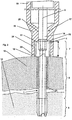
- Figure 1 shows a cross-sectional view of an embodiment of the inventive bone screw
- Figure 2 shows a cross-sectional view of the embodiment shown in Figure 1 , an implantation instrument, and a screwdriver;
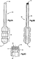
- Figure 3A shows a side view of an embodiment of a compression sleeve
- Figure 3B shows a cross-sectional view of the compression sleeve of Figure 3A ;
- Figure 3C shows an enlarged partial cross-sectional view of the compression sleeve of Figures 3A-3B ;
- Figure 4A shows a side view of an embodiment of a cannulated screwdriver
- Figure 4B shows a cross-sectional view of the screwdriver of Figure 4A ;
- Figure 5A shows a side view of an embodiment of a protection handle
- Figure 5B shows a cross-sectional view of the protection handle of Figure 5A ;
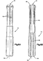
- Figure 6A shows a side view of a coupling member for use with the protection handle of Figures 5A-5B ;
- Figure 6B shows a cross-sectional view of the coupling member of Figure 6A ;
- Figure 7A show a side view of an embodiment of a combi-instrument
- Figures 7B-7C show cross-sectional views of the combi-instrument of Figure 7A ;
- Figure 8A shows a cross-sectional view of a compression sleeve for use with the combi-instrument of Figure 7A ;
- Figure 8B shows an enlarged cross-sectional view of the compression sleeve of Figure 8A ;
- Figure shows a side view of a handle for use with the combi-instrument of Figure 7A ;
- Figure 9B shows a cross-sectional view of the handle of Figure 9A ;
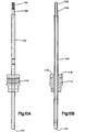
- Figure 10A shows a side view of a cannulated screwdriver and locking collar for use with the combi-instrument of Figure 7A ;
- Figure 10B shows a cross-sectional view of the cannulated screwdriver and locking collar of Figure 10A ;
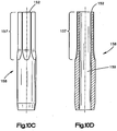
- Figure 10C shows an enlarged side view of the engagement portion of the cannulated screwdriver of Figures 10A-10B ;
- Figure 10D shows a cross-sectional view of the engagement portion of Figure 10C ;
- Figure 11A shows a side view of a locking ring for use with the combi- instrument of Figure 7A ;
- Figure 11B shows a cross-sectional view of the locking ring of Figure 11 A
- Figure 12A shows a side view of a locking collar for use with the combi-instrument of Figure 7A ;
- Figure 12B shows an end view of the locking collar of Figure 12A ;
- Figure 12C shows a cross-sectional view of the locking collar of Figure 12A ;
- Figure 13A shows a side view of an embodiment of a compression sleeve having a hex-shaped inlet for use with a plastic-sealed screw;
- Figure 13B shows an enlarged side view of the compression sleeve of Figure 13A ;
- Figure 13C shows an enlarged partial cross-sectional view of the compression sleeve of Figure 13A ;
- Figure 14A shows a side view of a plastic seal for use with a screw
- Figure 14B shows a cross-sectional view of the plastic seal of Figure 14A .
- FIG. 1 A preferred embodiment of the inventive bone screw 1 is shown in Figure 1 .
- This bone screw 1 includes a rear threaded segment 7 with an external thread 9, which has a core diameter D KH , an external diameter D HS and a pitch S H , a middle, threadless segment 6 with an external diameter D MS . which adjoins the rear threaded segment 7 coaxially with the longitudinal axis 2, and a front threaded segment 5 with an external thread 8, which has a core diameter D KV , an external diameter D VS and a pitch Sv.
- the two threaded segments 5, 7 have different diameters, that is, the core diameter D KH of the rear threaded segment 7 is larger than or equal to the external diameter D VS of the front threaded segment 5.
- the pitches of the two external threads 8, 9 may be identical, or may be different from one another.
- the lead of the front threaded segment 5 may be equal to or different from the lead of the rear threaded segment 7.
- the external diameter D MS of the middle segment 6 is smaller than or equal to the core diameter D KV of the front threaded segment 5.
- several indentations 23, distributed over the periphery of the two threaded segments 5, 7 which may be aligned axially, are disposed with cutting edges 12 essentially parallel to the longitudinal axis 2, so that these two external threads 8, 9 are constructed as self-cutting threads.
- means 11 for accommodating a screwdriver for example, a hexagonal recess, Torx® or Phillips, are disposed coaxially.
- the bone screw 1 is equipped with a central borehole 10, which extends from the front end 3 up to the rear end 4 and serves, for example, for accommodating a guiding wire (not shown).
- FIG 2 the inventive device is shown together with a bone screw 1 , a portion of the rear threaded segment 7 is screwed into the implantation instrument 15 and the front threaded segment 5 of which is screwed completely into the distal bone fragment 14.
- the implantation instrument 15 includes a continuous central borehole 17, which is expanded from the front end 18 up to a depth T and, in expanded part 24, has an internal thread 20, which is complementary to the external thread 9.
- a shoulder 22 against which the rear end 4 of the bone screw 1 rests when the rear threaded segment 7 is screwed completely into the implantation instrument 15.
- a screwdriver 16 can be passed through the narrower part 25 of the central borehole 17 from the rear end 19 of the implantation instrument 15, so that the screwdriver 16 can be introduced into the means 11, which are disposed at the rear end 4 of the bone screw 1 for accommodating a screwdriver and the bone screw 1 can be rotated by means of the screwdriver 16 relative to the implantation instrument 15.
- a borehole 21, passing through the proximal bone fragments 13 and into the distal bone fragment 14, may be produced.
- the diameter of the borehole 21 corresponds to the core diameter D KV ( Figure 1 ) of the external thread 8 at the front threaded segment 5 of the bone screw 1.
- Borehole 21 may be optional, however, particularly when bone screw 1 is self- drilling.
- the rear, threaded segment 7 of the bone screw 1 is screwed completely and up to a depth T in the internal thread 20 into the central borehole of the implantation instrument 15.
- the bone screw may then screwed into the pre-drilled boreholes 21 in the two bone fragments 13, 14. Since the rear threaded segment 7 of the bone screw 1 is taken up completely in the implantation instrument 15, the external thread 9 of the rear threaded segment 7 cannot engage the proximal bone fragments 13, so that, as the implantation instrument 15 is rotated, only the front threaded segment 5 of the bone screw 1 can be screwed into the distal bone fragment 14.
- the front end 18 of the implantation instrument 15 assumes the task of a screw head, so that, after the bone screw 1 has been brought into the two bone fragments 13, 14 far enough that the front end 18 of the implantation instrument 15 lies against the proximal bone fragment 14, the two bone fragments 13, 14 are moved towards one another by rotating the implantation instrument 15 further. As soon as the two bone fragments 13, 14 are in contact with one another, compression of the two bone fragments 13, 14 commences.
- the screwdriver 16 is inserted through the central borehole 17 in the implantation instrument 15 into the means 11 for accommodating the screwdriver and the bone screw 1 is rotated further with the screwdriver 16, so that, while the implantation instrument 15 is held in place, the bone screw 1 is screwed out of the internal thread 20 at the front end 18 of the implantation instrument 15 and the rear threaded segment 7 is screwed into the proximal bone fragment 13, until the rear threaded segment 7 is brought completely beneath the surface of the proximal bone fragment 13. Since the two bone fragments 13, 14 are not moved relative to one another during this last process, the compression may be unchanged after the rear, threaded segment 7 is driven into the proximal bone fragment 13.
- the bone screw 1 is used where a screw head would interfere, for example, for fractures in the vicinity of a joint, for intraarticular fixation such as scaphoid fractures, for small fragments and for fixations in the vicinity of sinews, nerves and vessels.
- Bone screw 1 may also be used in conjunction with or adjacent to a bone plate (not shown).
- FIGS. 3A-3C show an embodiment of a compression sleeve 30 for use with a bone screw 1.
- compression sleeve 30 may have a leading end 32, a trailing end 34, and a gripping portion 36 disposed near the trailing end 34.
- compression sleeve 30 may have a bore 38 running through the sleeve 30, and extending between leading opening 40 and trailing opening 42.
- An enlarged view of the leading end 32 of the compression sleeve 30 is seen in FIG. 3C .
- Internal threads 44 may be disposed at and/or near the leading end 32 and leading opening 40 of the sleeve 30.
- Sleeve 30 may also have a shoulder 46 disposed adjacent internal threads 40. Shoulder 46 may be sized to prevent a bone screw 1 from protruding too far into the bore 38 of sleeve 30. Shoulder 46 may be positioned within bore 38 such that the rear threaded segment 7 of bone screw 1 can fully engage the internal threads 40. Compression sleeve 30 may be used in a substantially similar manner as implantation instrument 15, discussed supra.
- FIGS. 4A-4B show an embodiment of a screwdriver 50 for use with a bone screw 1.
- screwdriver 50 may have an engaging end 52, a trailing end 54, and indicia 56a, 56b, 56c.
- Screwdriver 50 may also have a depressed section 58 at or near the trailing end 54, which may aid in engaging a handle.
- screwdriver 50 may have a bore 60 running between a leading opening 62 and a trailing opening 64.
- Screwdriver may also have an engaging portion 66 for engaging a bone screw 1 in a similar manner to that described supra in relation to screwdriver 16.
- Engaging portion 66 may be of any chosen shape to effectively engage a bone screw 1.
- Indicia 56a, 56b, 56c may aid in determining the depth of insertion of a bone screw 1 in a bone or tissue.
- indicia 56a, 56b, 56c may be fully or partially visible during use.
- the engaging portion 66 of the screwdriver 50 engages a receiving portion (an embodiment of which is shown as means 11 above) of a bone screw 1
- the bone screw 1 is further inserted in a bone or tissue, and may become disengaged with the internal threads 40 of a compression sleeve 30.
- the indicia 56a, 56b, 56c may progressively become covered, such that as indicia 56c becomes covered by sleeve 30, the bone screw 1 may be fully inserted into a bone or tissue.
- FIGS. 5A-5B show an embodiment of a handle 70 for use with an instrument described herein.
- handle 70 may have a gripping portion 72, and a coupling member 74 having an leading opening 76 and expandable fingers 82.
- Coupling member 74 may be a separate and distinct component (as shown in FIGS. 6A- 6B ), and may be at least partially inserted into a compression sleeve 30 via opening 42. Expandable fingers 82 may be beneficial to resiliently contract within bore 38 of compression 30 to create a more secure fit.
- handle 70 may also have a bore 78 for receiving coupling member 74.
- Receiving portion 74 may also have a bore 80 for receiving a portion of a guide wire (not shown) therethrough.
- FIGS. 6A-6B show an embodiment of a coupling member 74 in more detail.
- coupling member 74 may have leading opening 76, a trailing opening 86, with a bore 80 extending therebetween.
- Coupling member 74 may also have a leading end 85 and a trailing end 86.
- Bore 80 may be sized and dimensioned to fit a guide wire (not shown).
- handle 70 may be beneficial to provide a safe and ergonomic way for a user to insert bone screw 1 into a bone segment.
- a guide wire may be inserted into a bone segment at a desired location.
- the compression sleeve 30, with bone screw 1 already engaged with internal threads 40, may be engaged with handle 70, and thereafter inserted over the guide wire, such that the front end 3 of the bone screw 1 is adjacent the bone surface.
- the coupling portion 74 engages the compression sleeve 30 via its trailing opening 42, and the free end of the guide wire is housed in the bore 78 of handle 70.
- Bone screw 1 may then be inserted into the bone surface with the exposed, free end of the guide wire safely housed in the handle.
- the handle 70 and coupling portion 74 may be disengaged from the compression sleeve 30, and the screwdriver 50 may be brought into engagement to further insert the bone screw 1 into the bone surface and/or disengage the bone screw 1 from the compression sleeve 30.
- the configuration and removable engagement of handle 70 with compression sleeve 30 offers protection to the user from the free end of the guide wire, and also provides an ergonomic method to insert bone screw 1 at least partially into a bone surface.
- FIGS. 7A-7C show an embodiment of another type of instrument, combi-instrument 100, that may be used with a bone screw 1.
- combi-instrument 100 may have a handle 110, a locking collar 115, a locking ring 120, a compression sleeve 130 having a gripping portion 135 and a shaft portion 140, a screwdriver 150 having a leading portion 158, and a bore 160 extending therethrough.
- combi-instrument 100 may function in a substantially similar manner to that of the other devices described herein.
- combi-instrument 100 may have a selective engagement feature that allows a bone screw 1 to be at least partially inserted with and without the use of screwdriver 150.
- the selective locking arrangement between locking collar 115 and locking ring 120 may selectively determine whether the compression sleeve 130 is fixed in relation to the handle 110 and screwdriver 150.
- a guidewire (not shown) may be utilized for more precise and accurate placement and use of the instrument 100.
- FIGS. 8A-8B show an embodiment of a compression sleeve 130 for use with combi-instrument 100.
- Compression sleeve 130 may be substantially similar in design and function to compression sleeve 30 and implantation instrument 15 described supra.
- Compression sleeve 130 may have a bore 131 extending between a leading opening 133 and a trailing opening 132.
- Sleeve 130 may also have a gripping portion 135 and a shaft 140.
- sleeve 130 may also have internal threads 134 for engaging a bone screw 1, and a shoulder 136 for restricting movement of a bone screw 1 within bore 131.
- Compression sleeve 130 also may have an auxiliary shaft portion 139, which is either polygonal or otherwise non-circular in shape, for receiving a locking ring 120 such that when locking ring 120 is received on the auxiliary shaft, the locking ring 120 cannot rotate relative to the compression sleeve 130.
- compression sleeve 130 and locking ring 120 are rotationally fixed during use, although locking ring 120 may be slidably associated with the auxiliary shaft portion 139.
- FIGS. 9A-9B show an embodiment of a handle 110 for use with combi-instrument 100.
- Handle 110 may have a bore 111 extending between a leading opening 113 and a trailing opening 114. Handle 110 may also have a gripping portion 190, with indentations 192 for enhancing a user's gripping abilities. Handle 110 may further have an enlarged chamber 112, at least partially concurrent with bore 114, that may receive at least a portion of a locking collar 115. Handle 110 preferably is fixedly attached to locking collar 115 by way of fasteners (not shown) inserted into fixation holes 194.
- FIGS. 10A-10D show an embodiment of a cannulated screwdriver 150 for use with the combi-instrument 100.
- Screwdriver 150 may be substantially similar to screwdrivers 16, 50 described above.
- Screwdriver 150 may have a leading end 152, a trailing end 154, a bore 156, and a leading portion 158 at and/or near the leading end 152.
- screwdriver 150 may be sized to interact with locking collar 115.
- Leading portion 158 is shown in more detail in FIGS. 10C-10D .
- Leading portion 158 may have an engaging portion 157 for engaging a bone screw 1.
- Leading portion 158 may also have a bore 159 coaxial with but of a reduced diameter than bore 156 of screwdriver 150.
- Leading portion 158 may also be a separate and distinct component of screwdriver 150, and accordingly may be a least partially inserted into bore 156 of screwdriver 150. Any and all of the characteristics of leading portion 158 may also be used with screwdriver 16, 50. Screwdriver 150 may be fixedly attached to handle 110 during use.
- FIGS. 11A-11B show an embodiment of a locking ring 120 for use with combi-instrument 100.
- locking ring 120 may have indentations 122 to assist gripping, a first end 124, a second end 126, a first opening 125, and a second opening 123.
- Locking ring 120 may also have locking elements 127a, 127b protruding within the cavity 129 of locking ring 120. Locking elements 127a, 127b may engage indentations 118 of locking collar 115, as discussed below.
- Locking ring 120 may have one, two, three, or more locking elements.
- Inner surface 121 of locking ring 120 preferably corresponds to the shape and dimensions of auxiliary shaft portion 139 of compression sleeve 130.
- FIGS. 12A-12C show an embodiment of a locking collar 115 for use with combi-instrument 100.
- locking collar 115 may have an insertion end 117 for insertion into a handle 110, and an engaging end 119 for engaging a locking ring 120.
- Locking collar 115 may also have a bore 116 extending between ends 117, 119.
- the engaging end 119 of locking collar 115 may have a plurality of indentations 118 disposed around bore 116. Some indentations 118 may engage locking elements 127a, 127b of locking ring 120.
- Locking collar 115 is fixedly attached to handle 110 by way fasteners being inserted into fixation holes 196, which may align with the fixation holes 194 of handle 110. Fixation holes 194, 196 may be threaded.
- Locking collar 115 may also have indicia 191a, 191b, 191c, which may be utilized in a substantially similar manner as indicia 56a, 56b, 56c of screwdriver 50 (discussed supra), such that as the insertion of the bone screw 1 in a bone or tissue progresses, indicia 191 a, 191 b, 191 c are progressively covered up.
- Indicia 56, 191 may be different colors to indicate the level of insertion of bone screw 1.
- Indicia 56, 191 may be spaced apart as a variety of distances.
- Indicia 56, 191 are preferably spaced apart at about 2 mm.
- the combi-instrument 100 is arranged such that the locking elements 127 of the locking ring 120 engage indentations 118 of the locking collar 115.
- the entire combi- instrument 100 is essentially an integral tool.
- the combi-instrument 100 is then rotated and/or otherwise manipulated to insert bone screw 1 into a bone or tissue to a desired depth, but preferably such that the leading end 133 of the compression sleeve 130 is near the bone or tissue surface.
- the locking ring 120 may be slid toward the distal end of the device, such that locking elements 127 become disengaged with indentations 118 of locking collar 115.
- Locking ring 120 preferably is slid in this direction to the point that it abuts compression sleeve 130.
- handle 110 (with screwdriver 150 and locking collar 115 fixedly attached) may be rotated to further insert the bone screw 1 into a bone or tissue, while concurrently disengaging the rear threaded segment 7 from the internal threads 134 of the compression sleeve 130. This is achieved because the engaging portion 157 of the screwdriver 150 is now allowed to engage the bone screw 1 and rotate free of the compression sleeve 130 within its bore 131.
- FIGS. 13A-14B show another embodiment of a compression sleeve 200 and an embodiment of a plastic seal 220 for use with a bone screw 1, and in accordance with the overall objectives of the invention described herein.
- compression sleeve 200 may have a bore 202 extending between leading opening 204 and trailing opening 206. Bore 202 may have more than one diameter.
- Compression sleeve 200 may also have a shaft portion 208, and a tip portion 209 having a leading end 210. As seen in more detail in FIGS.
- tip portion 209 may have a hex-shaped inner surface 212 for receiving a portion of a plastic seal 220 (see FIGS. 14A-14B , infra). Inner surface 212 may be other shapes as well suitable for restricting rotational movement of a plastic seal 220 within the tip portion 209. Tip portion 209 may also have a ring 214 disposed near the leading end 210 for elastically securing a portion of a plastic seal 220. Ring 214 may be elastically deformable so as to allow a portion of a plastic seal 220 to engage the ring 214 while still allowing the plastic seal 220 to slide past the ring and further into the bore 202.
- FIGS. 14A-14B show an embodiment of a plastic seal 220 for use with compression sleeve 200 and bone screw 1.
- seal 220 may have a leading end 222, an insertion end 224, with a bore 226 extending between leading opening 230 and trailing opening 228.
- Seal 220 may also have a bulbous leading portion 234 for receiving a portion of a bone screw 1.
- the inner surface of the leading portion 234 may have a shoulder 232, similar in design and function to shoulder 22, 46, 136 described above.
- the inner surface of leading portion 234 may or may not be threaded.
- the inner surface is not threaded, and bone screw 1 is inserted into the leading portion 234 by axial force.
- inner surface is threaded, and bone screw 1 may be threadedly received within leading portion 234.
- Seal 220 may also be molded over at least a portion of bone screw 1.
- Seal 220 may also have a hex-shaped outer surface 236 at or near the insertion end 224, which may be inserted into the hex-shaped inner surface 212 of compression sleeve 200. Other shapes other than hex-shaped surfaces may be utilized.
- Seal 220 is preferably made of plastic, and is preferably a single-use, disposable element.
- bone screw 1 is inserted into the leading opening 230 of seal 220, and the insertion end 224 is inserted within the leading opening 204 of compression sleeve 200, such that the hex-shaped outer surface 236 of the seal 220 engages the hex-shaped inner surface 212 of the compression sleeve 200.
- Bone screw 1 may then be partially inserted into bone or tissue to a desired depth. Bone screw 1 may then be engaged by a screwdriver via bore 206 of compression sleeve 200 to insert screw 1 further into bone or tissue, and concurrently disengaging bone screw 1 with seal 220. Bone screw 1 may be engaged as such until the bone screw 1 is completely disengaged with seal 220.
- Plastic seal 220 may then be removed from compression sleeve 200 and discarded.
- Bone screw 1 may be fully or partially inserted into instrument 15 or compression sleeve 30, 130, 200 prior to engagement with a bone surface. Threaded portions of bone screw 1 may have a variety of pitches, lengths, diameters, and different threaded segments on a bone screw 1 may have the same or different pitches, lengths, and diameters. Various combinations of characteristics will be appreciated by those skilled in the art.
Landscapes
- Health & Medical Sciences (AREA)
- Orthopedic Medicine & Surgery (AREA)
- Life Sciences & Earth Sciences (AREA)
- Surgery (AREA)
- Medical Informatics (AREA)
- Engineering & Computer Science (AREA)
- Biomedical Technology (AREA)
- Heart & Thoracic Surgery (AREA)
- Nuclear Medicine, Radiotherapy & Molecular Imaging (AREA)
- Molecular Biology (AREA)
- Animal Behavior & Ethology (AREA)
- General Health & Medical Sciences (AREA)
- Public Health (AREA)
- Veterinary Medicine (AREA)
- Neurology (AREA)
- Surgical Instruments (AREA)
- Prostheses (AREA)
Abstract
Description
- The invention relates to a bone screw for connecting two bone fragments, to a device for implanting such a bone screw, and to a method for setting, compressing and/or fixing bone fragments.
- Bone screws are used in various ways in osteosynthesis, for example, for setting bone fragments, as compression screws or for fixing bone fragments. [0004] A bone screw with two axially terminal threaded segments and a middle threadless segment is known from United States patent no.
5,019,079 to Ross . The diameter of the middle segment corresponds essentially to the external diameter of the external thread at the distal threaded segment, but is larger than the core diameter of the external thread at the proximal threaded segment, so that the middle segment can be used for laterally stabilizing the two bone fragments of the fracture. It may be a disadvantage of this particular construction of bone screws that the two external threads have different pitches, so that the different steps for the implantation, the setting the bone fragments, the compression of the bone fragments and the recessing of the screw head cannot be carried out separately from one another. - Pursuant to the invention, this objective is accomplished with a bone screw, and with a device for implanting such a bone screw, as well as with a method for setting, compressing and/or fixing bone fragments.
- The inventive bone screw comprises essentially two threaded segments, which are disposed coaxially with the longitudinal axis and terminally at the bone screw, the pitches SV and SH of the front and rear segments respectively, which may be identical or may be different from one another. After these two bone fragments have been set and compressed, wherein only the front threaded segment is screwed into the distal bone fragment while the rear threaded segment is screwed, for example, into an implantation instrument and not yet into the proximal bone fragment, the bone screw can be screwed further into the bone fragments, until the rear threaded segment also is recessed completely in the proximal bone fragment. This can be accomplished without at the same time changing the position of the bone fragments relative to one another and without changing the compression of the two bone fragments. The two threaded segments are constructed so that the external diameter of the front threaded segment is smaller than or equal to the core diameter of the external thread at the rear threaded segment.
- An advantage of the inventive bone screw and the inventive device are that due to the pitch of the external thread at the front threaded segment and at the rear threaded segment being the same, the steps of setting the bone fragments, compressing the bone fragments, and recessing the head of the screw can be carried out separately and in a controlled manner.
- Because the rear threaded segment is configured with a core diameter, which may be larger than or equal to the external diameter of the front threaded segment, interaction of the rear threaded segment with the thread already cut in the bone fragments for the front threaded segment can be avoided.
- Preferably, the external threads at the front and rear threaded segments are self-cutting threads.
- A preferred embodiment of the inventive bone screw includes, between the two threaded segments, a middle, threadless segment, which has an external diameter, which is smaller than or equal to the core diameter of the external thread at the front threaded segment. With that, the front threaded segment can be screwed completely into the distal bone fragment and the borehole in the proximal bone fragment does not have to be enlarged relative to the borehole in the distal bone fragment for setting and compressing the bone fragments. Compared to embodiments of known bone screws, the front threaded segment of which directly adjoins the rear threaded segment in the axial direction and for which the borehole in the proximal bone fragment would have to be enlarged so that the front threaded segment can be screwed only into the distal bone fragment, a higher stability of the connection between the bone screw and the proximal bone fragment can furthermore be attained with the present device.
- The inventive device serves for setting, compressing and fixing bone fragments by means of a bone screw and includes a surgical implantation instrument, which has a central borehole through which a screwdriver can be passed, extending coaxially through the implantation instrument. Furthermore, the central borehole is expanded from the front end of the implantation instrument up to a depth T, so that a shoulder is formed at the depth T. In the expanded part of the central borehole, there is an internal thread, which is complementary to the external thread of the rear threaded segment of the bone screw, so that the rear threaded segment of the bone screw can be screwed into the central borehole up to a depth T. The depth T is selected so that T may be greater than L, where L is the length of the rear threaded segment of the bone screw. With that, it can be achieved that the rear threaded segment of the bone screw can be screwed completely into the central borehole of the implantation instrument. However, T may also be equal to or less than L, which may have the effect of partially inserting the rear threaded segment of the bone screw into the central borehole.
- The invention and further developments of the invention are explained in even greater detail in the following by means of the partially diagrammatic representations of several examples. In the drawings,
-
Figure 1 shows a cross-sectional view of an embodiment of the inventive bone screw; -
Figure 2 shows a cross-sectional view of the embodiment shown inFigure 1 , an implantation instrument, and a screwdriver; -
Figure 3A shows a side view of an embodiment of a compression sleeve; -
Figure 3B shows a cross-sectional view of the compression sleeve ofFigure 3A ; -
Figure 3C shows an enlarged partial cross-sectional view of the compression sleeve ofFigures 3A-3B ; -
Figure 4A shows a side view of an embodiment of a cannulated screwdriver; -
Figure 4B shows a cross-sectional view of the screwdriver ofFigure 4A ; -
Figure 5A shows a side view of an embodiment of a protection handle; -
Figure 5B shows a cross-sectional view of the protection handle ofFigure 5A ; -
Figure 6A shows a side view of a coupling member for use with the protection handle ofFigures 5A-5B ; -
Figure 6B shows a cross-sectional view of the coupling member ofFigure 6A ; -
Figure 7A show a side view of an embodiment of a combi-instrument; -
Figures 7B-7C show cross-sectional views of the combi-instrument ofFigure 7A ; -
Figure 8A shows a cross-sectional view of a compression sleeve for use with the combi-instrument ofFigure 7A ; -
Figure 8B shows an enlarged cross-sectional view of the compression sleeve ofFigure 8A ; - Figure shows a side view of a handle for use with the combi-instrument of
Figure 7A ; -
Figure 9B shows a cross-sectional view of the handle ofFigure 9A ; -
Figure 10A shows a side view of a cannulated screwdriver and locking collar for use with the combi-instrument ofFigure 7A ; -
Figure 10B shows a cross-sectional view of the cannulated screwdriver and locking collar ofFigure 10A ; -
Figure 10C shows an enlarged side view of the engagement portion of the cannulated screwdriver ofFigures 10A-10B ; -
Figure 10D shows a cross-sectional view of the engagement portion ofFigure 10C ; -
Figure 11A shows a side view of a locking ring for use with the combi- instrument ofFigure 7A ; -
Figure 11B shows a cross-sectional view of the locking ring ofFigure 11 A; -
Figure 12A shows a side view of a locking collar for use with the combi-instrument ofFigure 7A ; -
Figure 12B shows an end view of the locking collar ofFigure 12A ; -
Figure 12C shows a cross-sectional view of the locking collar ofFigure 12A ; -
Figure 13A shows a side view of an embodiment of a compression sleeve having a hex-shaped inlet for use with a plastic-sealed screw; -
Figure 13B shows an enlarged side view of the compression sleeve ofFigure 13A ; -
Figure 13C shows an enlarged partial cross-sectional view of the compression sleeve ofFigure 13A ; -
Figure 14A shows a side view of a plastic seal for use with a screw; and -
Figure 14B shows a cross-sectional view of the plastic seal ofFigure 14A . - A preferred embodiment of the
inventive bone screw 1 is shown inFigure 1 . Thisbone screw 1 includes a rear threadedsegment 7 with an external thread 9, which has a core diameter DKH, an external diameter DHS and a pitch SH, a middle,threadless segment 6 with an external diameter DMS. which adjoins the rear threadedsegment 7 coaxially with thelongitudinal axis 2, and a front threadedsegment 5 with anexternal thread 8, which has a core diameter DKV, an external diameter DVS and a pitch Sv. The two threadedsegments segment 7 is larger than or equal to the external diameter DVS of the front threadedsegment 5. The pitches of the twoexternal threads 8, 9 may be identical, or may be different from one another. Moreover, the lead of the front threadedsegment 5 may be equal to or different from the lead of the rear threadedsegment 7. The external diameter DMS of themiddle segment 6 is smaller than or equal to the core diameter DKV of the front threadedsegment 5. Moreover, at thefront end 3 of thebone screw 1 and at the transition between the rear threadedsegment 7 and themiddle segment 6,several indentations 23, distributed over the periphery of the two threadedsegments edges 12 essentially parallel to thelongitudinal axis 2, so that these twoexternal threads 8, 9 are constructed as self-cutting threads. At the rear end of 4 of thebone screw 1, means 11 for accommodating a screwdriver, for example, a hexagonal recess, Torx® or Phillips, are disposed coaxially. Moreover, thebone screw 1 is equipped with acentral borehole 10, which extends from thefront end 3 up to therear end 4 and serves, for example, for accommodating a guiding wire (not shown). - In
Figure 2 , the inventive device is shown together with abone screw 1 , a portion of the rear threadedsegment 7 is screwed into theimplantation instrument 15 and the front threadedsegment 5 of which is screwed completely into thedistal bone fragment 14. Theimplantation instrument 15 includes a continuouscentral borehole 17, which is expanded from thefront end 18 up to a depth T and, in expandedpart 24, has aninternal thread 20, which is complementary to the external thread 9. At the depth T, between the expandedpart 24 of thecentral borehole 17 and thenarrower part 25 of thecentral borehole 17, there is ashoulder 22, against which therear end 4 of thebone screw 1 rests when the rear threadedsegment 7 is screwed completely into theimplantation instrument 15. Ascrewdriver 16 can be passed through thenarrower part 25 of thecentral borehole 17 from therear end 19 of theimplantation instrument 15, so that thescrewdriver 16 can be introduced into themeans 11, which are disposed at therear end 4 of thebone screw 1 for accommodating a screwdriver and thebone screw 1 can be rotated by means of thescrewdriver 16 relative to theimplantation instrument 15. - For setting, compressing and fixing the two
bone fragments borehole 21, passing through the proximal bone fragments 13 and into thedistal bone fragment 14, may be produced. The diameter of theborehole 21 corresponds to the core diameter DKV (Figure 1 ) of theexternal thread 8 at the front threadedsegment 5 of thebone screw 1.Borehole 21 may be optional, however, particularly whenbone screw 1 is self- drilling. - At the start of the implantation process, the rear, threaded
segment 7 of thebone screw 1 is screwed completely and up to a depth T in theinternal thread 20 into the central borehole of theimplantation instrument 15. By rotating theimplantation instrument 15 about thelongitudinal axis 2, the bone screw may then screwed into thepre-drilled boreholes 21 in the twobone fragments segment 7 of thebone screw 1 is taken up completely in theimplantation instrument 15, the external thread 9 of the rear threadedsegment 7 cannot engage the proximal bone fragments 13, so that, as theimplantation instrument 15 is rotated, only the front threadedsegment 5 of thebone screw 1 can be screwed into thedistal bone fragment 14. In this phase, thefront end 18 of theimplantation instrument 15 assumes the task of a screw head, so that, after thebone screw 1 has been brought into the twobone fragments front end 18 of theimplantation instrument 15 lies against theproximal bone fragment 14, the twobone fragments implantation instrument 15 further. As soon as the twobone fragments bone fragments bone fragments implantation instrument 15 further, thescrewdriver 16 is inserted through thecentral borehole 17 in theimplantation instrument 15 into themeans 11 for accommodating the screwdriver and thebone screw 1 is rotated further with thescrewdriver 16, so that, while theimplantation instrument 15 is held in place, thebone screw 1 is screwed out of theinternal thread 20 at thefront end 18 of theimplantation instrument 15 and the rear threadedsegment 7 is screwed into theproximal bone fragment 13, until the rear threadedsegment 7 is brought completely beneath the surface of theproximal bone fragment 13. Since the twobone fragments segment 7 is driven into theproximal bone fragment 13. - Preferably, the
bone screw 1 is used where a screw head would interfere, for example, for fractures in the vicinity of a joint, for intraarticular fixation such as scaphoid fractures, for small fragments and for fixations in the vicinity of sinews, nerves and vessels.Bone screw 1 may also be used in conjunction with or adjacent to a bone plate (not shown). -
FIGS. 3A-3C show an embodiment of acompression sleeve 30 for use with abone screw 1. As seen in the side view ofFIG. 3A ,compression sleeve 30 may have aleading end 32, a trailingend 34, and a grippingportion 36 disposed near the trailingend 34. As seen in the cross-sectional view ofFIG. 3B ,compression sleeve 30 may have abore 38 running through thesleeve 30, and extending between leadingopening 40 and trailingopening 42. An enlarged view of theleading end 32 of thecompression sleeve 30 is seen inFIG. 3C .Internal threads 44 may be disposed at and/or near the leadingend 32 and leadingopening 40 of thesleeve 30.Sleeve 30 may also have ashoulder 46 disposed adjacentinternal threads 40.Shoulder 46 may be sized to prevent abone screw 1 from protruding too far into thebore 38 ofsleeve 30.Shoulder 46 may be positioned withinbore 38 such that the rear threadedsegment 7 ofbone screw 1 can fully engage theinternal threads 40.Compression sleeve 30 may be used in a substantially similar manner asimplantation instrument 15, discussed supra. -
FIGS. 4A-4B show an embodiment of ascrewdriver 50 for use with abone screw 1. As seen in the side view ofFIG. 4A ,screwdriver 50 may have anengaging end 52, a trailingend 54, andindicia Screwdriver 50 may also have adepressed section 58 at or near the trailingend 54, which may aid in engaging a handle. As seen in the cross-sectional view ofFIG. 4B ,screwdriver 50 may have abore 60 running between a leadingopening 62 and a trailingopening 64. Screwdriver may also have an engagingportion 66 for engaging abone screw 1 in a similar manner to that described supra in relation toscrewdriver 16. Engagingportion 66 may be of any chosen shape to effectively engage abone screw 1. -
Indicia bone screw 1 in a bone or tissue. When inserted into a compression sleeve or other implantation instrument,indicia portion 66 of thescrewdriver 50 engages a receiving portion (an embodiment of which is shown as means 11 above) of abone screw 1, thebone screw 1 is further inserted in a bone or tissue, and may become disengaged with theinternal threads 40 of acompression sleeve 30. As thescrewdriver 50 is inserted farther into thebore 38 ofsleeve 30, theindicia indicia 56c becomes covered bysleeve 30, thebone screw 1 may be fully inserted into a bone or tissue. -
FIGS. 5A-5B show an embodiment of ahandle 70 for use with an instrument described herein. As seen in the side view ofFIG. 5A , handle 70 may have a grippingportion 72, and acoupling member 74 having an leadingopening 76 andexpandable fingers 82. Couplingmember 74 may be a separate and distinct component (as shown inFIGS. 6A- 6B ), and may be at least partially inserted into acompression sleeve 30 viaopening 42.Expandable fingers 82 may be beneficial to resiliently contract within bore 38 ofcompression 30 to create a more secure fit. As seen in the cross-sectional view ofFIG. 5B , handle 70 may also have abore 78 for receivingcoupling member 74. Receivingportion 74 may also have abore 80 for receiving a portion of a guide wire (not shown) therethrough. -
FIGS. 6A-6B show an embodiment of acoupling member 74 in more detail. As seen in the side view ofFIG. 6A and cross-sectional view ofFIG. 6B ,coupling member 74 may have leadingopening 76, a trailingopening 86, with abore 80 extending therebetween. Couplingmember 74 may also have aleading end 85 and a trailingend 86.Bore 80 may be sized and dimensioned to fit a guide wire (not shown). - In use, handle 70 may be beneficial to provide a safe and ergonomic way for a user to insert
bone screw 1 into a bone segment. First, a guide wire may be inserted into a bone segment at a desired location. Thecompression sleeve 30, withbone screw 1 already engaged withinternal threads 40, may be engaged withhandle 70, and thereafter inserted over the guide wire, such that thefront end 3 of thebone screw 1 is adjacent the bone surface. In this arrangement, thecoupling portion 74 engages thecompression sleeve 30 via its trailingopening 42, and the free end of the guide wire is housed in thebore 78 ofhandle 70.Bone screw 1 may then be inserted into the bone surface with the exposed, free end of the guide wire safely housed in the handle. After thebone screw 1 is inserted into the bone surface to a desired depth, thehandle 70 andcoupling portion 74 may be disengaged from thecompression sleeve 30, and thescrewdriver 50 may be brought into engagement to further insert thebone screw 1 into the bone surface and/or disengage thebone screw 1 from thecompression sleeve 30. Thus, the configuration and removable engagement ofhandle 70 withcompression sleeve 30 offers protection to the user from the free end of the guide wire, and also provides an ergonomic method to insertbone screw 1 at least partially into a bone surface. -
FIGS. 7A-7C show an embodiment of another type of instrument, combi-instrument 100, that may be used with abone screw 1. As seen in the side view ofFIG. 7A , and cross-sectional views ofFIGS. 7B-7C , combi-instrument 100 may have ahandle 110, alocking collar 115, alocking ring 120, acompression sleeve 130 having a grippingportion 135 and ashaft portion 140, ascrewdriver 150 having a leadingportion 158, and abore 160 extending therethrough. - In use, combi-
instrument 100 may function in a substantially similar manner to that of the other devices described herein. One difference between the combi-instrument 100 and other devices described herein is that combi-instrument 100 may have a selective engagement feature that allows abone screw 1 to be at least partially inserted with and without the use ofscrewdriver 150. As described in more detail below, the selective locking arrangement between lockingcollar 115 and lockingring 120 may selectively determine whether thecompression sleeve 130 is fixed in relation to thehandle 110 andscrewdriver 150. Asbore 160 may pass all the way through the combi-instrument 100, a guidewire (not shown) may be utilized for more precise and accurate placement and use of theinstrument 100. -
FIGS. 8A-8B show an embodiment of acompression sleeve 130 for use with combi-instrument 100.Compression sleeve 130 may be substantially similar in design and function tocompression sleeve 30 andimplantation instrument 15 described supra.Compression sleeve 130 may have abore 131 extending between aleading opening 133 and a trailingopening 132.Sleeve 130 may also have agripping portion 135 and ashaft 140. As withcompression sleeve 30 discussed above,sleeve 130 may also haveinternal threads 134 for engaging abone screw 1, and ashoulder 136 for restricting movement of abone screw 1 withinbore 131.Compression sleeve 130 also may have anauxiliary shaft portion 139, which is either polygonal or otherwise non-circular in shape, for receiving alocking ring 120 such that when lockingring 120 is received on the auxiliary shaft, thelocking ring 120 cannot rotate relative to thecompression sleeve 130. As such,compression sleeve 130 and lockingring 120 are rotationally fixed during use, although lockingring 120 may be slidably associated with theauxiliary shaft portion 139. -
FIGS. 9A-9B show an embodiment of ahandle 110 for use with combi-instrument 100. Handle 110 may have abore 111 extending between aleading opening 113 and a trailingopening 114. Handle 110 may also have agripping portion 190, withindentations 192 for enhancing a user's gripping abilities. Handle 110 may further have anenlarged chamber 112, at least partially concurrent withbore 114, that may receive at least a portion of alocking collar 115. Handle 110 preferably is fixedly attached to lockingcollar 115 by way of fasteners (not shown) inserted into fixation holes 194. -
FIGS. 10A-10D show an embodiment of a cannulatedscrewdriver 150 for use with the combi-instrument 100.Screwdriver 150 may be substantially similar toscrewdrivers Screwdriver 150 may have aleading end 152, a trailingend 154, abore 156, and a leadingportion 158 at and/or near theleading end 152. As seen inFIGS. 10A-10B ,screwdriver 150 may be sized to interact with lockingcollar 115. Leadingportion 158 is shown in more detail inFIGS. 10C-10D . Leadingportion 158 may have anengaging portion 157 for engaging abone screw 1. Leadingportion 158 may also have abore 159 coaxial with but of a reduced diameter thanbore 156 ofscrewdriver 150. Leadingportion 158 may also be a separate and distinct component ofscrewdriver 150, and accordingly may be a least partially inserted intobore 156 ofscrewdriver 150. Any and all of the characteristics of leadingportion 158 may also be used withscrewdriver Screwdriver 150 may be fixedly attached to handle 110 during use. -
FIGS. 11A-11B show an embodiment of alocking ring 120 for use with combi-instrument 100. As seen in the side view ofFIG. 11A and the cross-sectional view ofFIG. 11B , lockingring 120 may haveindentations 122 to assist gripping, afirst end 124, asecond end 126, afirst opening 125, and asecond opening 123. Lockingring 120 may also have lockingelements cavity 129 of lockingring 120. Lockingelements indentations 118 of lockingcollar 115, as discussed below. Lockingring 120 may have one, two, three, or more locking elements.Inner surface 121 of lockingring 120 preferably corresponds to the shape and dimensions ofauxiliary shaft portion 139 ofcompression sleeve 130. -
FIGS. 12A-12C show an embodiment of alocking collar 115 for use with combi-instrument 100. As seen in the side view ofFIG. 12A , the front view ofFIG. 12B , and the cross-sectional view ofFIG. 12C , lockingcollar 115 may have aninsertion end 117 for insertion into ahandle 110, and anengaging end 119 for engaging alocking ring 120. Lockingcollar 115 may also have abore 116 extending betweenends FIG. 12B , theengaging end 119 of lockingcollar 115 may have a plurality ofindentations 118 disposed aroundbore 116. Someindentations 118 may engage lockingelements ring 120. Lockingcollar 115 is fixedly attached to handle 110 by way fasteners being inserted intofixation holes 196, which may align with the fixation holes 194 ofhandle 110. Fixation holes 194, 196 may be threaded. - Locking
collar 115 may also haveindicia indicia bone screw 1 in a bone or tissue progresses,indicia bone screw 1. Indicia 56, 191 may be spaced apart as a variety of distances. Indicia 56, 191 are preferably spaced apart at about 2 mm. - The engagement and release of locking
collar 115 with lockingring 120 will now be described. After thebone screw 1 is threaded attached tocompression sleeve 130 by engaginginternal threads 134 with the rear threadedsegment 7 ofbone screw 1 , the combi-instrument 100 is arranged such that the locking elements 127 of thelocking ring 120 engageindentations 118 of thelocking collar 115. In this configuration, the entire combi-instrument 100 is essentially an integral tool. The combi-instrument 100 is then rotated and/or otherwise manipulated to insertbone screw 1 into a bone or tissue to a desired depth, but preferably such that theleading end 133 of thecompression sleeve 130 is near the bone or tissue surface. At this point, thelocking ring 120 may be slid toward the distal end of the device, such that locking elements 127 become disengaged withindentations 118 of lockingcollar 115. Lockingring 120 preferably is slid in this direction to the point that it abutscompression sleeve 130. After lockingring 120 is disengaged, handle 110 (withscrewdriver 150 and lockingcollar 115 fixedly attached) may be rotated to further insert thebone screw 1 into a bone or tissue, while concurrently disengaging the rear threadedsegment 7 from theinternal threads 134 of thecompression sleeve 130. This is achieved because the engagingportion 157 of thescrewdriver 150 is now allowed to engage thebone screw 1 and rotate free of thecompression sleeve 130 within itsbore 131. -
FIGS. 13A-14B show another embodiment of acompression sleeve 200 and an embodiment of aplastic seal 220 for use with abone screw 1, and in accordance with the overall objectives of the invention described herein. As seen in the side view ofFIG. 13A , the enlarged side view ofFIG. 13B , and partial cross-sectional view ofFIG. 13C ,compression sleeve 200 may have abore 202 extending between leadingopening 204 and trailing opening 206.Bore 202 may have more than one diameter.Compression sleeve 200 may also have ashaft portion 208, and atip portion 209 having aleading end 210. As seen in more detail inFIGS. 13B-13C ,tip portion 209 may have a hex-shapedinner surface 212 for receiving a portion of a plastic seal 220 (seeFIGS. 14A-14B , infra).Inner surface 212 may be other shapes as well suitable for restricting rotational movement of aplastic seal 220 within thetip portion 209.Tip portion 209 may also have aring 214 disposed near theleading end 210 for elastically securing a portion of aplastic seal 220.Ring 214 may be elastically deformable so as to allow a portion of aplastic seal 220 to engage thering 214 while still allowing theplastic seal 220 to slide past the ring and further into thebore 202. -
FIGS. 14A-14B show an embodiment of aplastic seal 220 for use withcompression sleeve 200 andbone screw 1. As seen in the side view ofFIG. 14A , and the cross-sectional view ofFIG. 14B ,seal 220 may have aleading end 222, aninsertion end 224, with abore 226 extending between leadingopening 230 and trailingopening 228.Seal 220 may also have a bulbous leadingportion 234 for receiving a portion of abone screw 1. The inner surface of the leadingportion 234 may have ashoulder 232, similar in design and function toshoulder portion 234 may or may not be threaded. In one embodiment, the inner surface is not threaded, andbone screw 1 is inserted into the leadingportion 234 by axial force. In another embodiment, inner surface is threaded, andbone screw 1 may be threadedly received within leadingportion 234.Seal 220 may also be molded over at least a portion ofbone screw 1.Seal 220 may also have a hex-shapedouter surface 236 at or near theinsertion end 224, which may be inserted into the hex-shapedinner surface 212 ofcompression sleeve 200. Other shapes other than hex-shaped surfaces may be utilized.Seal 220 is preferably made of plastic, and is preferably a single-use, disposable element. - In use,
bone screw 1 is inserted into the leadingopening 230 ofseal 220, and theinsertion end 224 is inserted within the leadingopening 204 ofcompression sleeve 200, such that the hex-shapedouter surface 236 of theseal 220 engages the hex-shapedinner surface 212 of thecompression sleeve 200.Bone screw 1 may then be partially inserted into bone or tissue to a desired depth.Bone screw 1 may then be engaged by a screwdriver via bore 206 ofcompression sleeve 200 to insertscrew 1 further into bone or tissue, and concurrently disengagingbone screw 1 withseal 220.Bone screw 1 may be engaged as such until thebone screw 1 is completely disengaged withseal 220.Plastic seal 220 may then be removed fromcompression sleeve 200 and discarded. -
Bone screw 1 may be fully or partially inserted intoinstrument 15 orcompression sleeve bone screw 1 may have a variety of pitches, lengths, diameters, and different threaded segments on abone screw 1 may have the same or different pitches, lengths, and diameters. Various combinations of characteristics will be appreciated by those skilled in the art. - It is expressly contemplated that characteristics from some embodiments may be combined, integrated, or interchangeable with characteristics from other embodiments. In this sense, the described components of the instruments described herein are "modular" in nature. Such combinations will be appreciated by those skilled in the art, in addition to modifications thereof.
- While the invention has been shown and described herein with reference to particular embodiments, it is to be understood that the various additions, substitutions, or modifications of form, structure, arrangement, proportions, materials, and components and otherwise, used in the practice and which are particularly adapted to specific environments and operative requirements, may be made to the described embodiments without departing from the scope of the present invention. Accordingly, it should be understood that the embodiments disclosed herein are merely illustrative of the principles of the invention, and that various modifications may be made by those skilled in the art which will embody the principles of the invention and fall within the scope thereof.
Claims (13)
- A device for imparting a force on a screw, comprising:a sleeve (30) having a bore (38) therethrough, and an inner threaded portion (40) configured to engage the screw (1);a driving tool (50) at least partially received in the bore (38), and configured to engage the screw (1);wherein the driving tool (50) has a plurality of indicia (56a, 56b, 56c) configured to indicate the depth of insertion of the screw (1).
- The device of claim 1, wherein the plurality of indicia (56a, 56b, 56c) comprise grooves.
- The device of claim 1, wherein at least two indicia (56a, 56b, 56c) are different colors.
- The device of claim 1, further comprising a handle (70) removably associated with the sleeve (30).
- The device of claim 1, wherein the sleeve (30) further comprises a distal portion comprising a plastic seal (220).
- The device of claim 1, wherein the screw (1) has a front end having a first threaded portion (5), and a rear end having a second threaded portion (7).
- The device of claim 6, wherein the pitch of the first threaded portion (5) is substantially different than the pitch of the second threaded portion (7).
- The device of claim 6, wherein the pitch of the first threaded portion (5) is substantially equal to the pitch of the second threaded portion (7).
- The device of claim 6, wherein the lead of the first threaded portion (5) is substantially different than the lead of the second threaded portion (7).
- The device of claim 6, wherein the lead of the first threaded portion (5) is substantially equal to the lead of the second threaded portion (5).
- Assembly comprising a device of one of the claims 1 to 10 and a bone screw (1), wherein the bone screw (1) has a front end having a first threaded portion (5) with an external thread (8), and a rear end having a second threaded portion (7) with an external thread (9).
- The assembly of claim 1, wherein the inner threaded portion (40) of the sleeve (30) is configured to engage the external thread (9) on the second threaded portion (7) of the bone screw (1).
- Assembly according to claim 11 or 12 for setting, compressing and fixing bone fragments.
Applications Claiming Priority (2)
| Application Number | Priority Date | Filing Date | Title |
|---|---|---|---|
| US11/205,829 US8216243B2 (en) | 2001-12-04 | 2005-08-16 | Headless compression screw with integrated reduction-compression instrument |
| EP06801622.9A EP1916955B1 (en) | 2005-08-16 | 2006-08-15 | Headless compression screw with integrated reduction-compression instrument |
Related Parent Applications (2)
| Application Number | Title | Priority Date | Filing Date |
|---|---|---|---|
| EP06801622.9 Division | 2006-08-15 | ||
| EP06801622.9A Division EP1916955B1 (en) | 2005-08-16 | 2006-08-15 | Headless compression screw with integrated reduction-compression instrument |
Publications (3)
| Publication Number | Publication Date |
|---|---|
| EP2460485A2 true EP2460485A2 (en) | 2012-06-06 |
| EP2460485A3 EP2460485A3 (en) | 2014-03-19 |
| EP2460485B1 EP2460485B1 (en) | 2015-09-30 |
Family
ID=37561112
Family Applications (2)
| Application Number | Title | Priority Date | Filing Date |
|---|---|---|---|
| EP12000073.2A Active EP2460485B1 (en) | 2005-08-16 | 2006-08-15 | Headless compression screw with integrated reduction-compression instrument |
| EP06801622.9A Active EP1916955B1 (en) | 2005-08-16 | 2006-08-15 | Headless compression screw with integrated reduction-compression instrument |
Family Applications After (1)
| Application Number | Title | Priority Date | Filing Date |
|---|---|---|---|
| EP06801622.9A Active EP1916955B1 (en) | 2005-08-16 | 2006-08-15 | Headless compression screw with integrated reduction-compression instrument |
Country Status (11)
| Country | Link |
|---|---|
| US (3) | US8216243B2 (en) |
| EP (2) | EP2460485B1 (en) |
| JP (1) | JP5153633B2 (en) |
| KR (1) | KR101277775B1 (en) |
| CN (1) | CN101304699B (en) |
| AU (1) | AU2006279529A1 (en) |
| BR (1) | BRPI0615212B8 (en) |
| CA (2) | CA2854565C (en) |
| TW (1) | TWI468145B (en) |
| WO (1) | WO2007022261A2 (en) |
| ZA (1) | ZA200801473B (en) |
Cited By (1)
| Publication number | Priority date | Publication date | Assignee | Title |
|---|---|---|---|---|
| US12446941B2 (en) | 2020-04-16 | 2025-10-21 | DePuy Synthes Products, Inc. | Self-retaining screwdriver with slotted tip |
Families Citing this family (59)
| Publication number | Priority date | Publication date | Assignee | Title |
|---|---|---|---|---|
| US8216243B2 (en) | 2001-12-04 | 2012-07-10 | Synthes Usa, Llc | Headless compression screw with integrated reduction-compression instrument |
| IL162169A0 (en) * | 2001-12-04 | 2005-11-20 | Synthes Ag | Bone screw |
| BRPI0519961A2 (en) * | 2005-03-24 | 2009-04-07 | Synthes Gmbh | bone implant cement reinforcement device and method |
| US20080177333A1 (en) * | 2006-10-24 | 2008-07-24 | Warsaw Orthopedic, Inc. | Adjustable jacking implant |
| US20090005787A1 (en) * | 2007-06-28 | 2009-01-01 | Angela Crall | Device and system for implanting polyaxial bone fasteners |
| WO2010093658A2 (en) * | 2009-02-10 | 2010-08-19 | Synthes Usa, Llc | Screw with variable diameter cannulation and driver |
| US8366719B2 (en) | 2009-03-18 | 2013-02-05 | Integrated Spinal Concepts, Inc. | Image-guided minimal-step placement of screw into bone |
| US20100256688A1 (en) * | 2009-04-03 | 2010-10-07 | Stryker Trauma Gmbh | Sonic screw |
| US9808281B2 (en) * | 2009-05-20 | 2017-11-07 | DePuy Synthes Products, Inc. | Patient-mounted retraction |
| CN102018566B (en) * | 2009-09-17 | 2012-12-19 | 北京市春立正达医疗器械股份有限公司 | Metal mortar driver |
| US8545505B2 (en) | 2010-01-15 | 2013-10-01 | Pioneer Surgical Technology, Inc. | Low friction rod persuader |
| US9342716B2 (en) * | 2010-02-04 | 2016-05-17 | Carefusion 303, Inc. | Software-defined multi-mode RFID read devices |
| US8535318B2 (en) | 2010-04-23 | 2013-09-17 | DePuy Synthes Products, LLC | Minimally invasive instrument set, devices and related methods |
| US8512383B2 (en) | 2010-06-18 | 2013-08-20 | Spine Wave, Inc. | Method of percutaneously fixing a connecting rod to a spine |
| US8394108B2 (en) * | 2010-06-18 | 2013-03-12 | Spine Wave, Inc. | Screw driver for a multiaxial bone screw |
| US8641717B2 (en) | 2010-07-01 | 2014-02-04 | DePuy Synthes Products, LLC | Guidewire insertion methods and devices |
| WO2012012328A1 (en) * | 2010-07-20 | 2012-01-26 | X-Spine Systems, Inc. | Spinal facet compression screw with variable pitch thread zones and buttress head |
| US8945193B2 (en) | 2010-07-20 | 2015-02-03 | X-Spine Systems, Inc. | Minimally invasive spinal facet compression screw and system for bone joint fusion and fixation |
| US20120029577A1 (en) * | 2010-07-28 | 2012-02-02 | Sean Kerr | System and method for bone fixation using biodegradable screw having radial cutouts |
| ES2541207T3 (en) * | 2010-12-14 | 2015-07-16 | Stryker Trauma Sa | Fixing clamp with selector wheel |
| WO2012103354A1 (en) * | 2011-01-26 | 2012-08-02 | Del Palma Orthopedics, LLC | Upper extremity fusion devices |
| USD652138S1 (en) * | 2011-02-12 | 2012-01-10 | Eca Medical Instruments | Divoted medical instrument handle |
| DE102012104973A1 (en) * | 2011-09-22 | 2013-03-28 | Zbigniew Combrowski | Surgical instrument |
| EP2787913B1 (en) | 2011-12-06 | 2016-07-13 | Synthes GmbH | Self holding feature for a screw |
| WO2013123366A1 (en) | 2012-02-16 | 2013-08-22 | Paragon 28, Inc. | Charco-resis implant, alignment instrument, system and method of use |
| US9724149B2 (en) * | 2013-03-07 | 2017-08-08 | Warsaw Orhtopedic, Inc. | Surgical implant system and method |
| US9433445B2 (en) | 2013-03-14 | 2016-09-06 | DePuy Synthes Products, Inc. | Bone anchors and surgical instruments with integrated guide tips |
| US9504489B2 (en) * | 2013-06-12 | 2016-11-29 | Bradshaw Medical, Inc. | Cannulated medical instrument handle with an airspace |
| US9295500B2 (en) | 2013-06-12 | 2016-03-29 | Spine Wave, Inc. | Screw driver with release for a multiaxial bone screw |
| US9468479B2 (en) | 2013-09-06 | 2016-10-18 | Cardinal Health 247, Inc. | Bone plate |
| CA2932299C (en) * | 2013-12-26 | 2021-11-02 | Skeletal Dynamics, Llc | Headless compression screw |
| US9526553B2 (en) * | 2014-04-04 | 2016-12-27 | K2M, Inc. | Screw insertion instrument |
| US9855087B2 (en) | 2014-08-04 | 2018-01-02 | DePuy Synthes Products, LLC | Methods and devices for spinal screw insertion |
| JP2017501772A (en) * | 2014-10-06 | 2017-01-19 | ライト メディカル テクノロジー インコーポレイテッドWright Medical Technology, Inc. | Torque screwdriver for headless screw type compression fixture |
| CN105496501A (en) * | 2015-12-21 | 2016-04-20 | 武汉康斯泰德科技有限公司 | Threading type metal bone needle |
| US10426535B2 (en) | 2017-01-05 | 2019-10-01 | Stryker European Holdings I, Llc | Self-holding screw head |
| US10702324B2 (en) | 2017-02-27 | 2020-07-07 | Osteomed Llc | Reduction tool |
| US10433883B2 (en) | 2017-06-27 | 2019-10-08 | Medos International Sarl | Spinal screw insertion devices and methods |
| US10779872B2 (en) | 2017-11-02 | 2020-09-22 | Medos International Sarl | Bone anchor insertion instruments and methods |
| US10856924B2 (en) | 2017-12-21 | 2020-12-08 | Globus Medical Inc. | Headless compression screw driver system |
| US11832860B2 (en) | 2018-06-22 | 2023-12-05 | University Of Virginia Patent Foundation | Bone fixation system for promoting the union of a bone fracture and fusion of bones across a joint space and related methods thereof |
| USD957636S1 (en) | 2018-08-08 | 2022-07-12 | Medshape, Inc. | Low profile staple |
| US11224472B2 (en) * | 2019-06-13 | 2022-01-18 | Medos International Sarl | Screw inserter instruments and methods |
| US11123113B2 (en) * | 2019-06-13 | 2021-09-21 | Medos International Sarl | Screw inserter instruments and methods |
| US12004782B2 (en) | 2020-03-26 | 2024-06-11 | Warsaw Orthopedic, Inc. | Instrument for locking orthopedic screws |
| US12059189B2 (en) * | 2020-06-17 | 2024-08-13 | Arthrex, Inc. | Compression/reduction drivers for performing surgical methods |
| US11627998B2 (en) | 2020-12-11 | 2023-04-18 | Warsaw Orthopedic, Inc. | Head position and driver combination instrument |
| US11291488B1 (en) | 2021-02-24 | 2022-04-05 | Medshape, Inc. | Dynamic compression devices and processes for making and using same |
| USD1019954S1 (en) | 2021-02-24 | 2024-03-26 | Medshape, Inc. | Dynamic compression device |
| US12023068B2 (en) | 2021-03-02 | 2024-07-02 | Medshape, Inc. | Resorption-controlled compression devices and processes for making and using the same |
| US11291477B1 (en) | 2021-05-04 | 2022-04-05 | Warsaw Orthopedic, Inc. | Dorsal adjusting implant and methods of use |
| US11432848B1 (en) | 2021-05-12 | 2022-09-06 | Warsaw Orthopedic, Inc. | Top loading quick lock construct |
| US11712270B2 (en) | 2021-05-17 | 2023-08-01 | Warsaw Orthopedic, Inc. | Quick lock clamp constructs and associated methods |
| WO2022271504A1 (en) * | 2021-06-22 | 2022-12-29 | Smith & Nephew, Inc. | Self-countersinking bone fastener and method for countersinking a bone fastener used in connection with an orthopedic implant |
| US12527606B1 (en) | 2021-08-26 | 2026-01-20 | Medshape, Inc. | System and method for bone fixation based on bone quality |
| US11957391B2 (en) | 2021-11-01 | 2024-04-16 | Warsaw Orthopedic, Inc. | Bone screw having an overmold of a shank |
| US11679005B1 (en) * | 2022-05-26 | 2023-06-20 | Spinal Simplicity, Llc | Implant removal tool |
| US11832864B1 (en) | 2023-04-12 | 2023-12-05 | OC Medical Devices, LLC | Orthopedic implants and tools |
| US12178485B1 (en) | 2023-08-26 | 2024-12-31 | University Of Utah Research Foundation | Cannulated continuous compression screw |
Citations (1)
| Publication number | Priority date | Publication date | Assignee | Title |
|---|---|---|---|---|
| US5019079A (en) | 1989-11-20 | 1991-05-28 | Zimmer, Inc. | Bone screw |
Family Cites Families (30)
| Publication number | Priority date | Publication date | Assignee | Title |
|---|---|---|---|---|
| US2248054A (en) * | 1939-06-07 | 1941-07-08 | Becker Joseph | Screw driver |
| US2631584A (en) * | 1948-07-22 | 1953-03-17 | Alfred T Purificato | Fracture securing instrument |
| US4140111A (en) * | 1977-09-06 | 1979-02-20 | Morrill William E | Hand tool for inserting bone fracture pins |
| CH634742A5 (en) * | 1978-12-19 | 1983-02-28 | Synthes Ag | Device for fixing bone fragments |
| SU827050A1 (en) | 1979-03-26 | 1981-05-07 | Казанский Научно-Исследовательскийинститут Травматологии И Ортопедии | Osteosynthesis device |
| US4463753A (en) | 1980-01-04 | 1984-08-07 | Gustilo Ramon B | Compression bone screw |
| US4530355A (en) * | 1982-01-18 | 1985-07-23 | Richards Manufacturing Co., Inc. | Compression screw assembly |
| EP0209685A3 (en) * | 1985-07-12 | 1988-11-09 | Fischerwerke Arthur Fischer GmbH & Co. KG | Fixation element for osteosynthesis |
| US5324297A (en) * | 1989-01-31 | 1994-06-28 | Advanced Osseous Technologies, Inc. | Ultrasonic tool connector |
| US4963144A (en) * | 1989-03-17 | 1990-10-16 | Huene Donald R | Bone screw fixation assembly, bone screw therefor and method of fixation |
| IT1237496B (en) | 1989-10-26 | 1993-06-08 | Giuseppe Vrespa | SCREW DEVICE FOR ANCHORING BONE PROSTHESES, METHOD FOR THE APPLICATION OF SUCH DEVICE AND RELATED EQUIPMENT |
| DE9017101U1 (en) | 1990-12-19 | 1991-04-11 | Gerhard Hug Gmbh, 7801 Umkirch | Bone screw |
| US5766221A (en) * | 1991-12-03 | 1998-06-16 | Boston Scientific Technology, Inc. | Bone anchor implantation device |
| US6030162A (en) * | 1998-12-18 | 2000-02-29 | Acumed, Inc. | Axial tension screw |
| DE4307633C1 (en) | 1993-03-11 | 1994-05-19 | Pennig Dietmar | Screw for locking marrow-cavity pin in position - has threaded section of shank near head and opposite thread on head with unthreaded section of shank between |
| FR2706811A1 (en) * | 1993-06-25 | 1994-12-30 | Michelin & Cie | |
| US5431660A (en) * | 1993-11-30 | 1995-07-11 | Burke; Dennis W. | Spring loaded screw and driver/extractor therefor |
| US5536127A (en) | 1994-10-13 | 1996-07-16 | Pennig; Dietmar | Headed screw construction for use in fixing the position of an intramedullary nail |
| US5779704A (en) | 1996-03-19 | 1998-07-14 | Kim; Andrew C. | Bi-directional universal dynamic compression device |
| FR2758972B1 (en) | 1997-02-04 | 1999-05-07 | Eos Medical | THREADED HEAD SCREW DEVICE FOR ALLOWING FIXING OF SMALL BONE FRAGMENTS |
| US5941706A (en) * | 1997-10-20 | 1999-08-24 | Ura; Robert S. | Variable depth medical drill and method of making the same |
| DE10055888C1 (en) * | 2000-11-10 | 2002-04-25 | Biedermann Motech Gmbh | Bone screw, has connector rod receiving part with unsymmetrically arranged end bores |
| DE10129490A1 (en) | 2001-06-21 | 2003-01-02 | Helmut Mueckter | Implantable screw for stabilization of joint or bone fracture, has flexible shaft which interconnects proximal head portion and distal insertion portion of elongated screw body |
| JP2003019142A (en) * | 2001-07-05 | 2003-01-21 | Robert Reed Shokai Co Ltd | Medical driver |
| US20030093103A1 (en) * | 2001-08-08 | 2003-05-15 | Don Malackowski | Surgical tool system with components that perform inductive data transfer |
| US8216243B2 (en) | 2001-12-04 | 2012-07-10 | Synthes Usa, Llc | Headless compression screw with integrated reduction-compression instrument |
| IL162169A0 (en) | 2001-12-04 | 2005-11-20 | Synthes Ag | Bone screw |
| DE20203439U1 (en) | 2002-03-02 | 2003-07-17 | Chen, Eduard, Dr., 69118 Heidelberg | Surgical navigation screwdriver with fixing sleeve for screws with externally threaded heads has removable grip, integral tracker attachment sleeve for navigated computer-assisted applications |
| DE10224005B4 (en) | 2002-05-29 | 2015-08-13 | Stryker Leibinger Gmbh & Co. Kg | Cutting / bending system for fitting a bone plate |
| EP1594411A4 (en) * | 2003-02-03 | 2010-07-07 | Integra Lifesciences Corp | Compression screw apparatuses, systems and methods |
-
2005
- 2005-08-16 US US11/205,829 patent/US8216243B2/en not_active Expired - Lifetime
-
2006
- 2006-08-15 ZA ZA200801473A patent/ZA200801473B/en unknown
- 2006-08-15 CN CN200680038257XA patent/CN101304699B/en active Active
- 2006-08-15 JP JP2008527102A patent/JP5153633B2/en not_active Expired - Fee Related
- 2006-08-15 AU AU2006279529A patent/AU2006279529A1/en not_active Abandoned
- 2006-08-15 KR KR1020087003694A patent/KR101277775B1/en not_active Expired - Fee Related
- 2006-08-15 CA CA2854565A patent/CA2854565C/en active Active
- 2006-08-15 EP EP12000073.2A patent/EP2460485B1/en active Active
- 2006-08-15 WO PCT/US2006/031977 patent/WO2007022261A2/en not_active Ceased
- 2006-08-15 EP EP06801622.9A patent/EP1916955B1/en active Active
- 2006-08-15 BR BRPI0615212A patent/BRPI0615212B8/en active IP Right Grant
- 2006-08-15 CA CA2619047A patent/CA2619047C/en active Active
- 2006-08-16 TW TW95130114A patent/TWI468145B/en not_active IP Right Cessation
-
2012
- 2012-06-19 US US13/527,162 patent/US8540726B2/en not_active Expired - Fee Related
-
2013
- 2013-08-12 US US13/964,835 patent/US9113976B2/en not_active Expired - Fee Related
Patent Citations (1)
| Publication number | Priority date | Publication date | Assignee | Title |
|---|---|---|---|---|
| US5019079A (en) | 1989-11-20 | 1991-05-28 | Zimmer, Inc. | Bone screw |
Cited By (1)
| Publication number | Priority date | Publication date | Assignee | Title |
|---|---|---|---|---|
| US12446941B2 (en) | 2020-04-16 | 2025-10-21 | DePuy Synthes Products, Inc. | Self-retaining screwdriver with slotted tip |
Also Published As
| Publication number | Publication date |
|---|---|
| JP5153633B2 (en) | 2013-02-27 |
| EP2460485B1 (en) | 2015-09-30 |
| WO2007022261A3 (en) | 2007-07-05 |
| EP1916955B1 (en) | 2013-07-24 |
| US8216243B2 (en) | 2012-07-10 |
| BRPI0615212A2 (en) | 2011-05-10 |
| KR101277775B1 (en) | 2013-06-27 |
| US20060025773A1 (en) | 2006-02-02 |
| EP2460485A3 (en) | 2014-03-19 |
| CN101304699A (en) | 2008-11-12 |
| US20120283785A1 (en) | 2012-11-08 |
| ZA200801473B (en) | 2009-09-30 |
| WO2007022261A2 (en) | 2007-02-22 |
| CA2619047C (en) | 2014-08-05 |
| CA2854565C (en) | 2018-06-19 |
| EP1916955A2 (en) | 2008-05-07 |
| CA2619047A1 (en) | 2007-02-22 |
| BRPI0615212B1 (en) | 2018-02-14 |
| US20130331852A1 (en) | 2013-12-12 |
| US9113976B2 (en) | 2015-08-25 |
| TW200722035A (en) | 2007-06-16 |
| AU2006279529A1 (en) | 2007-02-22 |
| BRPI0615212B8 (en) | 2021-06-22 |
| CA2854565A1 (en) | 2007-02-22 |
| KR20080042825A (en) | 2008-05-15 |
| CN101304699B (en) | 2010-12-01 |
| US8540726B2 (en) | 2013-09-24 |
| TWI468145B (en) | 2015-01-11 |
| JP2009504336A (en) | 2009-02-05 |
Similar Documents
| Publication | Publication Date | Title |
|---|---|---|
| EP2460485B1 (en) | Headless compression screw with integrated reduction-compression instrument | |
| US7708738B2 (en) | Self-boring and self-tapping screw for osteosynthesis and compression | |
| US7582107B2 (en) | Compression screw apparatuses, systems and methods | |
| JP4728322B2 (en) | Adjustable tool for fasteners cannulated | |
| AU2005316909B2 (en) | Bone plate with pre-assembled drill guide tips | |
| US8460349B2 (en) | Bone screw | |
| US20070005070A1 (en) | Self-centering screw and retaining screw driver for use in surgery | |
| US20090198291A1 (en) | Bone screw | |
| RU2277392C2 (en) | Bone screw and device for setting, compressing and fixing bone fragments | |
| WO2006136037A1 (en) | Device for the fixation of bones |
Legal Events
| Date | Code | Title | Description |
|---|---|---|---|
| PUAI | Public reference made under article 153(3) epc to a published international application that has entered the european phase |
Free format text: ORIGINAL CODE: 0009012 |
|
| 17P | Request for examination filed |
Effective date: 20120109 |
|
| AC | Divisional application: reference to earlier application |
Ref document number: 1916955 Country of ref document: EP Kind code of ref document: P |
|
| AK | Designated contracting states |
Kind code of ref document: A2 Designated state(s): AT BE BG CH CY CZ DE DK EE ES FI FR GB GR HU IE IS IT LI LT LU LV MC NL PL PT RO SE SI SK TR |
|
| RIN1 | Information on inventor provided before grant (corrected) |
Inventor name: FRENK, ANDRE Inventor name: CICOIRA, FRANCO Inventor name: YEVMENENKO, YAN Inventor name: PISTOIA, WALTER Inventor name: BEUTTER, FLORIAN |
|
| PUAL | Search report despatched |
Free format text: ORIGINAL CODE: 0009013 |
|
| AK | Designated contracting states |
Kind code of ref document: A3 Designated state(s): AT BE BG CH CY CZ DE DK EE ES FI FR GB GR HU IE IS IT LI LT LU LV MC NL PL PT RO SE SI SK TR |
|
| RIC1 | Information provided on ipc code assigned before grant |
Ipc: A61B 17/86 20060101ALI20140213BHEP Ipc: A61B 17/00 20060101ALN20140213BHEP Ipc: A61B 17/88 20060101AFI20140213BHEP |
|
| RIC1 | Information provided on ipc code assigned before grant |
Ipc: A61B 17/86 20060101ALI20141128BHEP Ipc: A61B 17/88 20060101AFI20141128BHEP Ipc: A61B 17/00 20060101ALN20141128BHEP |
|
| RIC1 | Information provided on ipc code assigned before grant |
Ipc: A61B 17/00 20060101ALN20141212BHEP Ipc: A61B 17/88 20060101AFI20141212BHEP Ipc: A61B 17/86 20060101ALI20141212BHEP |
|
| RIC1 | Information provided on ipc code assigned before grant |
Ipc: A61B 17/88 20060101AFI20150123BHEP Ipc: A61B 17/86 20060101ALI20150123BHEP Ipc: A61B 17/00 20060101ALN20150123BHEP |
|
| RIC1 | Information provided on ipc code assigned before grant |
Ipc: A61B 17/88 20060101AFI20150302BHEP Ipc: A61B 17/00 20060101ALN20150302BHEP Ipc: A61B 17/86 20060101ALI20150302BHEP |
|
| GRAP | Despatch of communication of intention to grant a patent |
Free format text: ORIGINAL CODE: EPIDOSNIGR1 |
|
| RIC1 | Information provided on ipc code assigned before grant |
Ipc: A61B 17/86 20060101ALI20150327BHEP Ipc: A61B 17/00 20060101ALN20150327BHEP Ipc: A61B 17/88 20060101AFI20150327BHEP |
|
| INTG | Intention to grant announced |
Effective date: 20150430 |
|
| GRAS | Grant fee paid |
Free format text: ORIGINAL CODE: EPIDOSNIGR3 |
|
| GRAA | (expected) grant |
Free format text: ORIGINAL CODE: 0009210 |
|
| AC | Divisional application: reference to earlier application |
Ref document number: 1916955 Country of ref document: EP Kind code of ref document: P |
|
| AK | Designated contracting states |
Kind code of ref document: B1 Designated state(s): AT BE BG CH CY CZ DE DK EE ES FI FR GB GR HU IE IS IT LI LT LU LV MC NL PL PT RO SE SI SK TR |
|
| REG | Reference to a national code |
Ref country code: CH Ref legal event code: EP Ref country code: GB Ref legal event code: FG4D |
|
| REG | Reference to a national code |
Ref country code: AT Ref legal event code: REF Ref document number: 751912 Country of ref document: AT Kind code of ref document: T Effective date: 20151015 |
|
| REG | Reference to a national code |
Ref country code: IE Ref legal event code: FG4D |
|
| REG | Reference to a national code |
Ref country code: DE Ref legal event code: R096 Ref document number: 602006046841 Country of ref document: DE |
|
| REG | Reference to a national code |
Ref country code: CH Ref legal event code: NV Representative=s name: E. BLUM AND CO. AG PATENT- UND MARKENANWAELTE , CH |
|
| PG25 | Lapsed in a contracting state [announced via postgrant information from national office to epo] |
Ref country code: FI Free format text: LAPSE BECAUSE OF FAILURE TO SUBMIT A TRANSLATION OF THE DESCRIPTION OR TO PAY THE FEE WITHIN THE PRESCRIBED TIME-LIMIT Effective date: 20150930 Ref country code: GR Free format text: LAPSE BECAUSE OF FAILURE TO SUBMIT A TRANSLATION OF THE DESCRIPTION OR TO PAY THE FEE WITHIN THE PRESCRIBED TIME-LIMIT Effective date: 20151231 Ref country code: LT Free format text: LAPSE BECAUSE OF FAILURE TO SUBMIT A TRANSLATION OF THE DESCRIPTION OR TO PAY THE FEE WITHIN THE PRESCRIBED TIME-LIMIT Effective date: 20150930 Ref country code: LV Free format text: LAPSE BECAUSE OF FAILURE TO SUBMIT A TRANSLATION OF THE DESCRIPTION OR TO PAY THE FEE WITHIN THE PRESCRIBED TIME-LIMIT Effective date: 20150930 |
|
| REG | Reference to a national code |
Ref country code: NL Ref legal event code: MP Effective date: 20150930 |
|
| REG | Reference to a national code |
Ref country code: LT Ref legal event code: MG4D |
|
| REG | Reference to a national code |
Ref country code: AT Ref legal event code: MK05 Ref document number: 751912 Country of ref document: AT Kind code of ref document: T Effective date: 20150930 |
|
| PG25 | Lapsed in a contracting state [announced via postgrant information from national office to epo] |
Ref country code: SE Free format text: LAPSE BECAUSE OF FAILURE TO SUBMIT A TRANSLATION OF THE DESCRIPTION OR TO PAY THE FEE WITHIN THE PRESCRIBED TIME-LIMIT Effective date: 20150930 |
|
| PG25 | Lapsed in a contracting state [announced via postgrant information from national office to epo] |
Ref country code: ES Free format text: LAPSE BECAUSE OF FAILURE TO SUBMIT A TRANSLATION OF THE DESCRIPTION OR TO PAY THE FEE WITHIN THE PRESCRIBED TIME-LIMIT Effective date: 20150930 Ref country code: IS Free format text: LAPSE BECAUSE OF FAILURE TO SUBMIT A TRANSLATION OF THE DESCRIPTION OR TO PAY THE FEE WITHIN THE PRESCRIBED TIME-LIMIT Effective date: 20160130 Ref country code: SK Free format text: LAPSE BECAUSE OF FAILURE TO SUBMIT A TRANSLATION OF THE DESCRIPTION OR TO PAY THE FEE WITHIN THE PRESCRIBED TIME-LIMIT Effective date: 20150930 Ref country code: EE Free format text: LAPSE BECAUSE OF FAILURE TO SUBMIT A TRANSLATION OF THE DESCRIPTION OR TO PAY THE FEE WITHIN THE PRESCRIBED TIME-LIMIT Effective date: 20150930 Ref country code: CZ Free format text: LAPSE BECAUSE OF FAILURE TO SUBMIT A TRANSLATION OF THE DESCRIPTION OR TO PAY THE FEE WITHIN THE PRESCRIBED TIME-LIMIT Effective date: 20150930 Ref country code: NL Free format text: LAPSE BECAUSE OF FAILURE TO SUBMIT A TRANSLATION OF THE DESCRIPTION OR TO PAY THE FEE WITHIN THE PRESCRIBED TIME-LIMIT Effective date: 20150930 |
|
| PG25 | Lapsed in a contracting state [announced via postgrant information from national office to epo] |
Ref country code: AT Free format text: LAPSE BECAUSE OF FAILURE TO SUBMIT A TRANSLATION OF THE DESCRIPTION OR TO PAY THE FEE WITHIN THE PRESCRIBED TIME-LIMIT Effective date: 20150930 Ref country code: PL Free format text: LAPSE BECAUSE OF FAILURE TO SUBMIT A TRANSLATION OF THE DESCRIPTION OR TO PAY THE FEE WITHIN THE PRESCRIBED TIME-LIMIT Effective date: 20150930 Ref country code: PT Free format text: LAPSE BECAUSE OF FAILURE TO SUBMIT A TRANSLATION OF THE DESCRIPTION OR TO PAY THE FEE WITHIN THE PRESCRIBED TIME-LIMIT Effective date: 20160201 Ref country code: RO Free format text: LAPSE BECAUSE OF FAILURE TO SUBMIT A TRANSLATION OF THE DESCRIPTION OR TO PAY THE FEE WITHIN THE PRESCRIBED TIME-LIMIT Effective date: 20150930 |
|
| REG | Reference to a national code |
Ref country code: DE Ref legal event code: R097 Ref document number: 602006046841 Country of ref document: DE |
|
| REG | Reference to a national code |
Ref country code: FR Ref legal event code: PLFP Year of fee payment: 11 |
|
| PLBE | No opposition filed within time limit |
Free format text: ORIGINAL CODE: 0009261 |
|
| STAA | Information on the status of an ep patent application or granted ep patent |
Free format text: STATUS: NO OPPOSITION FILED WITHIN TIME LIMIT |
|
| PG25 | Lapsed in a contracting state [announced via postgrant information from national office to epo] |
Ref country code: DK Free format text: LAPSE BECAUSE OF FAILURE TO SUBMIT A TRANSLATION OF THE DESCRIPTION OR TO PAY THE FEE WITHIN THE PRESCRIBED TIME-LIMIT Effective date: 20150930 |
|
| 26N | No opposition filed |
Effective date: 20160701 |
|
| PG25 | Lapsed in a contracting state [announced via postgrant information from national office to epo] |
Ref country code: SI Free format text: LAPSE BECAUSE OF FAILURE TO SUBMIT A TRANSLATION OF THE DESCRIPTION OR TO PAY THE FEE WITHIN THE PRESCRIBED TIME-LIMIT Effective date: 20150930 |
|
| PG25 | Lapsed in a contracting state [announced via postgrant information from national office to epo] |
Ref country code: BE Free format text: LAPSE BECAUSE OF FAILURE TO SUBMIT A TRANSLATION OF THE DESCRIPTION OR TO PAY THE FEE WITHIN THE PRESCRIBED TIME-LIMIT Effective date: 20150930 |
|
| PG25 | Lapsed in a contracting state [announced via postgrant information from national office to epo] |
Ref country code: MC Free format text: LAPSE BECAUSE OF FAILURE TO SUBMIT A TRANSLATION OF THE DESCRIPTION OR TO PAY THE FEE WITHIN THE PRESCRIBED TIME-LIMIT Effective date: 20150930 |
|
| REG | Reference to a national code |
Ref country code: IE Ref legal event code: MM4A |
|
| REG | Reference to a national code |
Ref country code: FR Ref legal event code: PLFP Year of fee payment: 12 |
|
| PG25 | Lapsed in a contracting state [announced via postgrant information from national office to epo] |
Ref country code: IE Free format text: LAPSE BECAUSE OF NON-PAYMENT OF DUE FEES Effective date: 20160815 |
|
| REG | Reference to a national code |
Ref country code: DE Ref legal event code: R082 Ref document number: 602006046841 Country of ref document: DE Representative=s name: KLUNKER IP PATENTANWAELTE PARTG MBB, DE |
|
| PG25 | Lapsed in a contracting state [announced via postgrant information from national office to epo] |
Ref country code: LU Free format text: LAPSE BECAUSE OF NON-PAYMENT OF DUE FEES Effective date: 20160815 |
|
| PG25 | Lapsed in a contracting state [announced via postgrant information from national office to epo] |
Ref country code: CY Free format text: LAPSE BECAUSE OF FAILURE TO SUBMIT A TRANSLATION OF THE DESCRIPTION OR TO PAY THE FEE WITHIN THE PRESCRIBED TIME-LIMIT Effective date: 20150930 Ref country code: HU Free format text: LAPSE BECAUSE OF FAILURE TO SUBMIT A TRANSLATION OF THE DESCRIPTION OR TO PAY THE FEE WITHIN THE PRESCRIBED TIME-LIMIT; INVALID AB INITIO Effective date: 20060815 |
|
| PG25 | Lapsed in a contracting state [announced via postgrant information from national office to epo] |
Ref country code: TR Free format text: LAPSE BECAUSE OF FAILURE TO SUBMIT A TRANSLATION OF THE DESCRIPTION OR TO PAY THE FEE WITHIN THE PRESCRIBED TIME-LIMIT Effective date: 20150930 |
|
| REG | Reference to a national code |
Ref country code: FR Ref legal event code: PLFP Year of fee payment: 13 |
|
| PG25 | Lapsed in a contracting state [announced via postgrant information from national office to epo] |
Ref country code: BG Free format text: LAPSE BECAUSE OF FAILURE TO SUBMIT A TRANSLATION OF THE DESCRIPTION OR TO PAY THE FEE WITHIN THE PRESCRIBED TIME-LIMIT Effective date: 20150930 |
|
| PGFP | Annual fee paid to national office [announced via postgrant information from national office to epo] |
Ref country code: DE Payment date: 20240702 Year of fee payment: 19 |
|
| PGFP | Annual fee paid to national office [announced via postgrant information from national office to epo] |
Ref country code: GB Payment date: 20240701 Year of fee payment: 19 |
|
| PGFP | Annual fee paid to national office [announced via postgrant information from national office to epo] |
Ref country code: FR Payment date: 20240702 Year of fee payment: 19 |
|
| PGFP | Annual fee paid to national office [announced via postgrant information from national office to epo] |
Ref country code: CH Payment date: 20240901 Year of fee payment: 19 |
|
| PGFP | Annual fee paid to national office [announced via postgrant information from national office to epo] |
Ref country code: IT Payment date: 20240710 Year of fee payment: 19 |
|
| REG | Reference to a national code |
Ref country code: DE Ref legal event code: R119 Ref document number: 602006046841 Country of ref document: DE |
|
| REG | Reference to a national code |
Ref country code: CH Ref legal event code: H13 Free format text: ST27 STATUS EVENT CODE: U-0-0-H10-H13 (AS PROVIDED BY THE NATIONAL OFFICE) Effective date: 20260324 |
|
| PG25 | Lapsed in a contracting state [announced via postgrant information from national office to epo] |
Ref country code: CH Free format text: LAPSE BECAUSE OF NON-PAYMENT OF DUE FEES Effective date: 20250831 |
|
| GBPC | Gb: european patent ceased through non-payment of renewal fee |
Effective date: 20250815 |