EP2459904B1 - Electronically controlled range valve for multi-speed planetary transmission - Google Patents
Electronically controlled range valve for multi-speed planetary transmission Download PDFInfo
- Publication number
- EP2459904B1 EP2459904B1 EP10804864.6A EP10804864A EP2459904B1 EP 2459904 B1 EP2459904 B1 EP 2459904B1 EP 10804864 A EP10804864 A EP 10804864A EP 2459904 B1 EP2459904 B1 EP 2459904B1
- Authority
- EP
- European Patent Office
- Prior art keywords
- shift
- fluid
- valve
- shift valve
- electro
- Prior art date
- Legal status (The legal status is an assumption and is not a legal conclusion. Google has not performed a legal analysis and makes no representation as to the accuracy of the status listed.)
- Not-in-force
Links
Images


Classifications
-
- F—MECHANICAL ENGINEERING; LIGHTING; HEATING; WEAPONS; BLASTING
- F16—ENGINEERING ELEMENTS AND UNITS; GENERAL MEASURES FOR PRODUCING AND MAINTAINING EFFECTIVE FUNCTIONING OF MACHINES OR INSTALLATIONS; THERMAL INSULATION IN GENERAL
- F16H—GEARING
- F16H59/00—Control inputs to control units of change-speed- or reversing-gearings for conveying rotary motion
- F16H59/02—Selector apparatus
- F16H59/04—Ratio selector apparatus
- F16H59/045—Ratio selector apparatus consisting of fluid valves
-
- F—MECHANICAL ENGINEERING; LIGHTING; HEATING; WEAPONS; BLASTING
- F16—ENGINEERING ELEMENTS AND UNITS; GENERAL MEASURES FOR PRODUCING AND MAINTAINING EFFECTIVE FUNCTIONING OF MACHINES OR INSTALLATIONS; THERMAL INSULATION IN GENERAL
- F16H—GEARING
- F16H61/00—Control functions within control units of change-speed- or reversing-gearings for conveying rotary motion ; Control of exclusively fluid gearing, friction gearing, gearings with endless flexible members or other particular types of gearing
- F16H61/02—Control functions within control units of change-speed- or reversing-gearings for conveying rotary motion ; Control of exclusively fluid gearing, friction gearing, gearings with endless flexible members or other particular types of gearing characterised by the signals used
- F16H61/0202—Control functions within control units of change-speed- or reversing-gearings for conveying rotary motion ; Control of exclusively fluid gearing, friction gearing, gearings with endless flexible members or other particular types of gearing characterised by the signals used the signals being electric
- F16H61/0204—Control functions within control units of change-speed- or reversing-gearings for conveying rotary motion ; Control of exclusively fluid gearing, friction gearing, gearings with endless flexible members or other particular types of gearing characterised by the signals used the signals being electric for gearshift control, e.g. control functions for performing shifting or generation of shift signal
- F16H61/0206—Layout of electro-hydraulic control circuits, e.g. arrangement of valves
-
- F—MECHANICAL ENGINEERING; LIGHTING; HEATING; WEAPONS; BLASTING
- F16—ENGINEERING ELEMENTS AND UNITS; GENERAL MEASURES FOR PRODUCING AND MAINTAINING EFFECTIVE FUNCTIONING OF MACHINES OR INSTALLATIONS; THERMAL INSULATION IN GENERAL
- F16H—GEARING
- F16H59/00—Control inputs to control units of change-speed- or reversing-gearings for conveying rotary motion
- F16H59/02—Selector apparatus
- F16H59/08—Range selector apparatus
-
- F—MECHANICAL ENGINEERING; LIGHTING; HEATING; WEAPONS; BLASTING
- F16—ENGINEERING ELEMENTS AND UNITS; GENERAL MEASURES FOR PRODUCING AND MAINTAINING EFFECTIVE FUNCTIONING OF MACHINES OR INSTALLATIONS; THERMAL INSULATION IN GENERAL
- F16H—GEARING
- F16H61/00—Control functions within control units of change-speed- or reversing-gearings for conveying rotary motion ; Control of exclusively fluid gearing, friction gearing, gearings with endless flexible members or other particular types of gearing
- F16H61/04—Smoothing ratio shift
- F16H61/0437—Smoothing ratio shift by using electrical signals
-
- F—MECHANICAL ENGINEERING; LIGHTING; HEATING; WEAPONS; BLASTING
- F16—ENGINEERING ELEMENTS AND UNITS; GENERAL MEASURES FOR PRODUCING AND MAINTAINING EFFECTIVE FUNCTIONING OF MACHINES OR INSTALLATIONS; THERMAL INSULATION IN GENERAL
- F16H—GEARING
- F16H61/00—Control functions within control units of change-speed- or reversing-gearings for conveying rotary motion ; Control of exclusively fluid gearing, friction gearing, gearings with endless flexible members or other particular types of gearing
- F16H61/12—Detecting malfunction or potential malfunction, e.g. fail safe ; Circumventing or fixing failures
- F16H2061/1204—Detecting malfunction or potential malfunction, e.g. fail safe ; Circumventing or fixing failures for malfunction caused by simultaneous engagement of different ratios resulting in transmission lock state or tie-up condition
-
- F—MECHANICAL ENGINEERING; LIGHTING; HEATING; WEAPONS; BLASTING
- F16—ENGINEERING ELEMENTS AND UNITS; GENERAL MEASURES FOR PRODUCING AND MAINTAINING EFFECTIVE FUNCTIONING OF MACHINES OR INSTALLATIONS; THERMAL INSULATION IN GENERAL
- F16H—GEARING
- F16H61/00—Control functions within control units of change-speed- or reversing-gearings for conveying rotary motion ; Control of exclusively fluid gearing, friction gearing, gearings with endless flexible members or other particular types of gearing
- F16H61/12—Detecting malfunction or potential malfunction, e.g. fail safe ; Circumventing or fixing failures
- F16H2061/1244—Keeping the current state
-
- F—MECHANICAL ENGINEERING; LIGHTING; HEATING; WEAPONS; BLASTING
- F16—ENGINEERING ELEMENTS AND UNITS; GENERAL MEASURES FOR PRODUCING AND MAINTAINING EFFECTIVE FUNCTIONING OF MACHINES OR INSTALLATIONS; THERMAL INSULATION IN GENERAL
- F16H—GEARING
- F16H61/00—Control functions within control units of change-speed- or reversing-gearings for conveying rotary motion ; Control of exclusively fluid gearing, friction gearing, gearings with endless flexible members or other particular types of gearing
- F16H61/12—Detecting malfunction or potential malfunction, e.g. fail safe ; Circumventing or fixing failures
- F16H2061/1256—Detecting malfunction or potential malfunction, e.g. fail safe ; Circumventing or fixing failures characterised by the parts or units where malfunctioning was assumed or detected
- F16H2061/1288—Detecting malfunction or potential malfunction, e.g. fail safe ; Circumventing or fixing failures characterised by the parts or units where malfunctioning was assumed or detected the failing part is an actuator
-
- F—MECHANICAL ENGINEERING; LIGHTING; HEATING; WEAPONS; BLASTING
- F16—ENGINEERING ELEMENTS AND UNITS; GENERAL MEASURES FOR PRODUCING AND MAINTAINING EFFECTIVE FUNCTIONING OF MACHINES OR INSTALLATIONS; THERMAL INSULATION IN GENERAL
- F16H—GEARING
- F16H2200/00—Transmissions for multiple ratios
- F16H2200/003—Transmissions for multiple ratios characterised by the number of forward speeds
- F16H2200/0052—Transmissions for multiple ratios characterised by the number of forward speeds the gear ratios comprising six forward speeds
-
- F—MECHANICAL ENGINEERING; LIGHTING; HEATING; WEAPONS; BLASTING
- F16—ENGINEERING ELEMENTS AND UNITS; GENERAL MEASURES FOR PRODUCING AND MAINTAINING EFFECTIVE FUNCTIONING OF MACHINES OR INSTALLATIONS; THERMAL INSULATION IN GENERAL
- F16H—GEARING
- F16H61/00—Control functions within control units of change-speed- or reversing-gearings for conveying rotary motion ; Control of exclusively fluid gearing, friction gearing, gearings with endless flexible members or other particular types of gearing
- F16H61/68—Control functions within control units of change-speed- or reversing-gearings for conveying rotary motion ; Control of exclusively fluid gearing, friction gearing, gearings with endless flexible members or other particular types of gearing specially adapted for stepped gearings
- F16H61/684—Control functions within control units of change-speed- or reversing-gearings for conveying rotary motion ; Control of exclusively fluid gearing, friction gearing, gearings with endless flexible members or other particular types of gearing specially adapted for stepped gearings without interruption of drive
- F16H61/686—Control functions within control units of change-speed- or reversing-gearings for conveying rotary motion ; Control of exclusively fluid gearing, friction gearing, gearings with endless flexible members or other particular types of gearing specially adapted for stepped gearings without interruption of drive with orbital gears
-
- Y—GENERAL TAGGING OF NEW TECHNOLOGICAL DEVELOPMENTS; GENERAL TAGGING OF CROSS-SECTIONAL TECHNOLOGIES SPANNING OVER SEVERAL SECTIONS OF THE IPC; TECHNICAL SUBJECTS COVERED BY FORMER USPC CROSS-REFERENCE ART COLLECTIONS [XRACs] AND DIGESTS
- Y10—TECHNICAL SUBJECTS COVERED BY FORMER USPC
- Y10T—TECHNICAL SUBJECTS COVERED BY FORMER US CLASSIFICATION
- Y10T74/00—Machine element or mechanism
- Y10T74/20—Control lever and linkage systems
- Y10T74/20012—Multiple controlled elements
- Y10T74/20018—Transmission control
- Y10T74/20024—Fluid actuator
Definitions
- the present invention relates generally to power transmissions for motor vehicles, and more particularly, to a shift by wire control system for a power transmission including an electronically controlled range valve.
- An electro-hydraulic control system controls shifting and operation of automatic vehicle transmissions.
- the electro-hydraulic control system typically includes either a manual valve or a shift by wire valve.
- the vehicle operator manually changes the position of the valve to accomplish certain shifts, for example, to initiate movement of the vehicle from a non-moving state to a moving state or vice versa, or to change the direction in which the vehicle is moving (i.e., shifts from neutral to a forward range, from neutral to a reverse range, from a reverse range to a forward range, from a reverse range to neutral, from a forward range to neutral, or from a forward range to a reverse range).
- a push button range selector may be used in a shift by wire system.
- Activation of a push button or similar actuator by the vehicle operator sends an electrical signal to an electronic control unit.
- the electronic control unit executes computer logic to determine which valve(s) in the electro-hydraulic control system need to change position in order for pressurized hydraulic fluid to be directed to the appropriate clutches to accomplish the requested shift.
- the electronic control unit sends electrical signals to solenoid valves of the electro-hydraulic control system, which initiate the valve position changes required to accomplish the requested shift.
- DE 10 2007 025997 A1 describes an electro-hydraulic control system for a transmission having first, second, and third selectively engageable torque transmitting mechanisms.
- the control system includes a main source of fluid pressure and first, second, and third trim valves operable to effect the engagement of respective first, second, and third torque transmitting mechanisms.
- a latch valve is in fluid communication with the first torque transmitting mechanism and an interlock valve is in selective fluid communication with the latch valve.
- the first trim valve, latch valve, and interlock valve are in fluid communication with the main source of fluid pressure.
- the first trim valve operates selectively communicate fluid pressure to the latch valve to effect engagement of the first torque transmitting mechanism, while the interlock valve is operable to selectively communicate fluid pressure to one of the second and third trim valve to effect engagement of the respective second and third torque transmitting mechanisms.
- Said document does not disclose a fourth shift valve having at least first, second and third spaced-apart lands, wherein the first and second lands define a chamber and the second and third lands define a further chamber.
- an electro-hydraulic control system for a multi-speed vehicle transmission comprising:
- the electro-hydraulic control may include a torque converter clutch control valve, wherein the torque converter clutch control valve is coupled to at least one of the first, second, third and fourth shift valves.
- the plurality of fluid passages may selectively couple the first, second, third, and fourth shift valves such that a first reverse range can be achieved whether the fourth shift valve is in the first position or the second position.
- the plurality of fluid passages may selectively couple the first, second, third, and fourth shift valves such that a neutral range can be achieved whether the fourth shift valve is in the first position or the second position.
- the plurality of fluid passages may selectively couple the first, second, third and fourth shift valves such that at least two of the shift valves are required to change position in order for the transmission to shift from a neutral range to a forward range.
- the electro-hydraulic control may include first and second trim systems each configured to receive electrical signals from the electrical control and control the rate at which fluid pressure is delivered to the shift mechanisms of the transmission via the first, second, third, and fourth shift valves, wherein the first trim system is directly fluidly coupled to the first shift valve, the second trim system is directly fluidly coupled to the second shift valve, the second trim system is fluidly coupled to the third shift valve via the second shift valve, and the second trim system is fluidly coupled to the first shift valve via the second and third shift valves.
- the fluid passages may selectively couple the first, second, third and fourth shift valves such that at least one of the trim systems and at least one of the shift valves are required to be actuated in order for the transmission to shift from a neutral range to a reverse range.
- Fluid in the first and second fluid chambers of the fourth shift valve may be at an exhaust pressure in neutral and reverse ranges during normal operation and also during an electrical failure.
- the first land may have a first diameter
- the second land may have a second diameter
- the third land may have a third diameter, where the second diameter is larger than the first diameter, and the third diameter is larger than the second diameter.
- the electro-hydraulic control may apply fluid pressure to a differential area of the third land of the fourth shift valve to keep the fourth shift valve in the second position during an electrical failure occurring in a low forward range.
- the low forward range may be a forward range lower than a fourth forward range.
- the electro-hydraulic control may apply fluid pressure to a differential area of the second land of the fourth shift valve to keep the fourth shift valve in the second position during an electrical failure occurring in a high forward range.
- the high forward range may be a forward range higher than a third forward range.
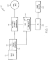
- Fig. 1 depicts a simplified block diagram of an electro-hydraulic transmission control 20 including a shift by wire valve 26, in the context of an exemplary vehicle powertrain 10.
- the lines shown as connecting blocks 12, 14, 16, 18, 20, 22, 24, 26, 28 of powertrain 10 represent connections which, in practice, may include one or more electrical, mechanical and/or fluid connections, passages, couplings or linkages, as will be understood by those skilled in the art and as described herein.
- Powertrain 10 includes drive unit 12, torque converter 14, torque converter clutch 16, transmission 18, electro-hydraulic control 20, electronic control 22, range selector 24, and final drive 28.
- Drive unit 12 generally provides a torque output to torque converter 14.
- Drive unit 12 may be an internal combustion engine of a compression-ignition type (i.e. diesel) or a spark-ignition type (i.e. gasoline), a hybrid unit, or other suitable unit for generating torque output to drive a vehicle.
- Torque converter 14 selectively establishes a coupling between drive unit 12 and transmission 18 to convert and/or transfer the torque output from drive unit 12 to the vehicle transmission 18.
- Such coupling is a fluid coupling when torque converter clutch 16 is not applied, and a mechanical coupling when torque converter clutch is applied.
- Torque converter clutches are often provided to effect unitary rotation of the torque converter pump and turbine in response to reduced hydraulic pressure within the torque converter, which may occur when "slip" (i.e., a difference in rotational speed) between the torque converter pump and turbine is not required.
- Transmission 18 includes an input shaft, an output shaft, an assembly of gears, and a plurality of gear-shifting mechanisms that are selectively engaged and disengaged by electro-hydraulic transmission control 20 to cause the vehicle to assume one of a plurality of operational modes or ranges including at least six forward speed ratios, a neutral range, and at least one reverse range.
- the shift mechanisms of transmission 18 are in fluid communication with hydraulic control elements of control 20.
- shift mechanism may be used to refer to one or more clutches, brakes, or other friction elements or devices, or similar suitable mechanisms configured to cause the transmission to switch from one range or gear ratio to another, different range or gear ratio.
- Control 20 includes a two-position shift valve 26 that allows for shifting into reverse and neutral ranges when in one position and allows for shifting into forward ranges when in its other position.
- reverse and neutral ranges are achieved when shift valve 26 is in an off or de-actuated position and forward ranges are achievable when shift valve 26 is in the on or actuated position.
- shift valve 26 can control three modes of operation (reverse, neutral, and forward ranges) with only two positions. The structure and operation of shift valve 26 is described in more detail below.
- control 20 including shift valve 26 also denoted by fourth shift valve shown in Figs. 2-13 relates to a six-speed vehicle transmission that includes three planetary gearsets and five shift mechanisms (e.g. two rotating shift mechanisms and three stationary shift mechanisms C1, C2, C3, C4, C5). During normal operation of transmission 18, two shift mechanisms are engaged in each range except neutral.
- An illustrative embodiment of transmission 18 is disclosed in U.S. Patent No. 4,070,927 to Polak . Those of ordinary skill in the art will understand that such transmission is offered only as an example, and that aspects of the present invention are applicable to other multi-speed vehicle transmissions.
- transmission 18 has a shift schedule as shown in Table 1 below. TABLE 1 Range Clutches Applied Reverse C3, C5 Neutral C5 1st C1, C5 2 nd C1, C4 3 rd C1, C3 4 th C1, C2 5 th C2, C3 6 th C2, C4
- shift mechanisms C1, C2, C3, C4, and C5 may be applied and released to achieve particular operating ranges of the transmission.
- the torque output by transmission 18 is applied to the final drive 28.
- the final drive 20 generally includes the drive wheels and driven load mass carried by the vehicle. Characteristics of final drive 20 may vary considerably over the course of the vehicle's use, as may be the case particularly with commercial vehicles such as trucks, buses, emergency vehicles, and the like.
- Electrical control 22 controls operation of transmission 18 based on inputs from one or more components of drive unit 12, torque converter 14, transmission 18, range selector 24; and/or other inputs.
- Such inputs may include electrical digital and/or analog signals received from sensors, controls or other like devices associated with the vehicle components.
- inputs may include signals indicative of transmission input speed, driver requested torque, engine output torque, engine speed, temperature of the hydraulic fluid, transmission output speed, turbine speed, brake position, gear ratio, torque converter slip, and/or other measurable parameters.
- Electrical control 22 generally includes electrical circuitry configured to process, analyze or evaluate one or more of the inputs and issue electrical control signals to appropriate components of electro-hydraulic control system 20, as needed, through one or more electrical lines, conductors, or other suitable connections.
- Such connections may include hard-wired and/or networked components in any suitable configuration including, for example, insulated wiring and/or wireless transmission as may be appropriate or desired.
- Range selector 24 issues signals or commands indicative of a selected or desired operational mode of the vehicle, i.e., a selected or desired forward speed ratio, a desired reverse range, or neutral.
- range selector 24 is an electronically-controlled or "shift-by-wire" range selecting mechanism, rather than a manual selector.
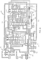
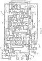
- control 20 includes two-position shift valve 26, three additional shift valves 36, 38, 40, also denoted by first, second and third shift valves, and three clutch pressure control or "trim" systems 30, 32, and 34.
- Fluid circuits including a main pressure circuit 60, a control pressure circuit 62, and an exhaust circuit 64, are coupled to a source of pressurized fluid (not shown). Fluid circuits 60, 62, 64 fluidly couple the hydraulic components of control 20 to one another as shown and described below.
- main pressure circuit 60 draws hydraulic fluid at a main pressure from a fluid supply, such as a sump or reservoir (not shown).
- a fluid supply such as a sump or reservoir (not shown).
- the main pressure defines a range including a minimum system pressure and a maximum system pressure for main pressure circuit 60.
- the main pressure is in the range of about 50-250 pounds per square inch (psi).
- main pressure is denoted using a backward-slash pattern.
- Control pressure circuit 62 circulates hydraulic fluid at a control pressure, which is typically regulated by a regulator or modulator valve as will be understood.
- control pressure is generally in the range of about 50-110 psi. Control pressure is denoted in the drawings by a dotted pattern.
- Exhaust circuit 64 is in fluid communication with components of control 20 as shown in the drawings. Exhaust pressure is in the range of about zero psi. Exhaust circuit 64 is operably coupled to an exhaust backfill regulator valve 44. The EBF valve 44 provides an exhaust backfill pressure, which is configured to prevent air from entering exhausted clutches. In the illustrated embodiment, the exhaust backfill pressure is generally in the range of about 2 psi. In the drawings, exhaust pressure is denoted by a forward-slash pattern.
- restrictors or orifices 80, 82, 84, 86, 88 are also shown.
- the restrictors or orifices 80, 82, 84, 86, 88 are positioned in fluid passages to alter or moderate the rate of fluid flow through the passages or a portion thereof, in order to control the rate at which pressure in a fluid passage changes.
- These elements are typically used to provide additional control over fluid pressure in the passages.
- series of orifices 80, 82, 84 are used to prevent actuation of pressure switches 72, 74, 76 from occurring until their corresponding shift valve 38, 40, 26 is fully stroked.
- Electro-hydraulic actuators 50, 52, 54, 56 also denoted by first, second, third and fourth electro-hydraulic actuators, and pressure switches 70, 72, 74, 76 are in fluid communication with each of the shift valves 36, 38, 40, 26, respectively. It will be understood that actuators 50, 52, 54, 56, and pressure switches 70, 72, 74, 76 are electrically coupled to control 22, although for ease understanding these electrical connections are not shown in Figs. 2-13 .
- each of the valves of control 20 includes a valve head, a valve spool, at least one valve land interposed between portions of the valve spool or between the valve head and a portion of the valve spool, and a return spring disposed in a spring chamber.
- Each valve spool is axially translatable in a valve bore in response to changes in fluid pressure or fluid flow through the various passages of control 20.
- the valve bores have been omitted from the figures.
- valve lands each define a diameter that is greater than the diameter defined by the valve spool, such that surfaces of the lands may slidably engage interior surfaces of the valve bore when the valve spool translates within the valve bore.
- Spool portions between valve lands may selectively connect fluid passages to other fluid passages, or connect fluid passages to fluid chambers, depending on the position of the valve.
- Each of shift valves 36, 38, 40 has more than four spaced-apart lands that define at least four fluid chambers therebetween.
- Shift valve 26 has four spaced-apart lands that define three fluid chambers therebetween.
- Shift valves 36 and 40 are generally single-diameter shift valves, meaning that all of the valve's lands have substantially the same diameter or there is no pressure differential.
- Shift valve 38 is a two-diameter shift valve, with land 166 having a smaller diameter than land 168, as best shown in Figs. 8 and 10 .
- the land above land 166 (nearest the valve head) on shift valve 38 has substantially the same diameter as land 166, and the lands below land 168 (nearer to the return spring) have substantially the same diameter as land 168.
- Shift valve 26 is a three-diameter shift valve.
- Land 172 has a larger diameter than land 170, and land 174 has a larger diameter than land 172 as best shown in Figs. 11-13 .
- Land 176 has substantially the same diameter as land 174.
- the height of land 174 is smaller than the heights of the other lands 170, 172 and 176.
- shift valves 26, 38 allow control 20 to use valve latching to provide failure recovery from any range of transmission 18 in the event of an electrical failure.
- the latching features on shift valve 26 additionally serve to hold shift valve 26 in the stroked position as long as a forward range is commanded, thereby preventing an unintended shift out of a forward range in the event that shift valve 26 fails.
- return springs 180, 182, 184, 186, 188 bias their respective valve in a destroked position. Changes in fluid pressure or fluid flow in selected fluid passages may cause the valve spool to translate within the valve bore, causing the return spring to partially or fully compress.
- shift valves 36, 38, 40, 26 are slidable between the destroked position and a stroked position, where the stroked position is one in which the return spring is fully compressed.
- each of actuators 50, 52, 54, 56 is a solenoid valve of the on/off type.
- the positioning of the shift valves 36, 38, 40, 26 determines which of the shift mechanisms Cl, C2, C3, C4, C5 receive fluid pressure and which do not, thereby controlling which shift mechanisms are applied and which are released at any given time.
- the pressure control valves of clutch trim systems 30, 32, 34 are configured to assume intermediate positions between the first and second positions, in which the return spring is partially compressed, in addition to the first and second positions.
- the displacement of the pressure control valves of the clutch trim systems 30, 32, 34 is controlled by electro-hydraulic actuators that have a variable output pressure, such as variable-bleed solenoids. Because the rate of application of fluid pressure can be controlled in this way, clutch trim systems 30, 32, 34 control the rate at which a shift mechanism is applied or released.
- Clutch trim systems 30 and 32 control the rate of application or release of the shift mechanisms C1, C2, C3, C4, C5 (depending on the positioning of the shift valves 26, 36, 38, 40), while clutch trim system 34 controls the rate of application or release of torque converter clutch 14.
- Actuators 50, 52, 54, 56 and the variable-output electro-hydraulic actuators of the clutch trim systems 30, 32, 34 are operably coupled to control 22 to receive electrical signals (i.e. electrical current) therefrom.
- the electrical signals generated and sent by control 22 to the electro-hydraulic actuators of control 20 selectively actuate the valves (in response to driver input or other inputs) to accomplish shifting of transmission 18.
- Each of the electro-hydraulic actuators of control 20 is either of the normally low type or of the normally high type.
- a normally low (or normally off) solenoid valve provides maximum output pressure when it receives electrical input and provides zero or minimum output pressure when no electrical input is received; while a normally high (or normally on) solenoid valve provides maximum output pressure when it is not receiving any electrical input and provides zero or minimum output pressure when electrical input is provided.
- actuated when referring to an actuator or solenoid valve as being “actuated,” this means either that electrical input is supplied to the solenoid (as in the case of normally low solenoids) or that electrical input is not supplied to the solenoid (as in the case of normally high solenoids).
- each of actuators 50, 52, 54, 56 is a normally low solenoid
- the electro-hydraulic actuators of trim systems 32 and 34 are normally low solenoids
- the electro-hydraulic actuator of trim system 30 is a normally high solenoid.
- pressure switches 70, 72, 74, 76 are each configured to issue an electrical output signal to control 22 in response to a predetermined fluid pressure being detected by the pressure switch, for diagnostic purposes or for other reasons. Such electrical signals inform control 22 of changes in status of components of control 20. Generation of an output signal by pressure switches 70, 72, 74 can be triggered either by the presence or the absence of a predetermined level of fluid pressure, depending on the configuration of the switch.
- the term "actuated" when used to describe activity of a pressure switch means simply that the switch has issued an output signal to control 22, without limiting the pressure switch to a particular type or configuration.
- each shift valve 26, 36, 38, 40 has a corresponding pressure switch 76, 70, 72, 74, in fluid communication therewith.
- Each of pressure switches 70, 72, 74, 76 acts as a binary switch such that it is actuated when the shift valve to which it is coupled is in the stroked position.
- Control 20 may include other pressure switches in addition to those used to monitor the position of the shift valves. For example, control 20 may use pressure switches to detect changes in position of the trim valves 30, 32, 34, representing also the trim systems.
- Table 2 shows a steady state mechanization of components of control 20 during normal operation.
- the number "1” is used to denote that a component is actuated, while the number “0” denotes that a component is not actuated.
- the mechanization of trim system 34 is omitted from Table 2 because the application of torque converter clutch 14 is controlled independently by trim system actuator 58.
- control 20 during normal operation, including two possible reverse ranges, a neutral range, and multiple forward ranges, will now be described.
- control 20 provides two alternative reverse ranges.
- Reverse1 shift valve actuators 52 and 54 are actuated, causing shift valves 38 and 40 to move to the stroked position while shift valve 36 remains in the destroked position due to actuator 50 being non-actuated.
- Trim system 30 is fluidly coupled to fluid chamber 148 as a result of actuation of shift valve 38 by actuator 52. As a result, trim system 30 applies main pressure to shift mechanism C5 through fluid chamber 148 and fluid passage 94.
- trim system 32 is fluidly coupled to fluid chamber 150 via fluid chamber 144 of shift valve 36, fluid passage 100, fluid chamber 152 of shift valve 40, and fluid passage 98. As a result, trim system 32 applies main pressure to shift mechanism C3 via fluid chamber 150 and fluid passage 96.
- the fluid chambers 192, 190, 150, 156 and 148 are also denoted by first, second, third, fourth and fifth fluid chambers.
- Shift valve 26 is not actuated in the Reverse1 range. However, even if shift valve 26 were actuated in the Reverse1 range, control 20 would remain in the Reverse1 range because the fluid passages 104, 108 (which feed shift mechanisms C1, C2 respectively when shift valve 26 is stroked) are connected to exhaust pressure. Thus, the Reverse1 range can be achieved and maintained regardless of the position of shift valve 26. Moreover, in order for control 20 to fail to a forward range, two valve malfunctions would have to occur, e.g. a failure of shift valve 26 and a failure of at least one of the other shift valves 36, 38,40, or a failure of shift valve 26 and a failure of one of the trim systems 30,32.
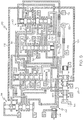
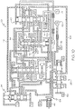
- a neutral range configuration of control 20 is shown in Fig. 4 .
- all three shift valves 36, 38, 40 are actuated by control pressure supplied by actuators 50, 52, 54 respectively.
- pressure switches 70, 72, 74 are actuated.
- Shift valve 26 is not actuated in the neutral range and therefore, the neutral range can be attained and maintained independently of shift valve 26.
- trim system 30 supplies main pressure to shift mechanism C5 via passage 128, fluid chamber 148, and passage 94.
- trim system 32 In order to transition from the neutral range of Fig. 4 to either of the reverse ranges of Figs. 2 and 3 , trim system 32 would have to be actuated and either shift valve 36 (for Reverse1 range) or shift valve 38 (for Reverse2 range) would have to change position.
- shift valve 26 and at least one other shift valve 36, 38, 40 have to change position.
- control 20 provides protection against unintentional shifting out of neutral into a moving range by requiring at least two valves to change position.
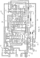
- Exemplary forward range configurations of control 20 are shown in Figs. 5 , 6 , and 7 .
- Each of the forward ranges requires either shift mechanism C1 or shift mechanism C2 to be applied.
- Both shift mechanism C1 and C2 are in fluid communication with shift valve 26.
- shift valve 26 When shift valve 26 is not actuated (i.e. destroked), both shift mechanism C1 and shift mechanism C2 are in direct fluid communication with exhaust backfill circuit 64 and EBF valve 44 as shown in Figs. 2-4 . Movement of shift valve 26 to the on or stroked position is initiated by actuator 56 independently of the other valve systems of control 20.
- shifting from a non-forward range into a forward range can only be accomplished if shift valve 26 is in the actuated or stroked position shown in Figs. 5 , 6 , and 7 .
- shift valve 26 is in the on or stroked position in all forward ranges, as indicated by Table 2.
- Actuator 56 is actuated by electrical signals issued by control 22 in response to a forward range request received from range selector 24 in the form of an electrical signal.
- control 20 is configured so that transitions from non-forward ranges to a forward range only occur if an electrical forward range request signal has been received by control 22.
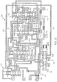
- Fig. 5 shows a configuration of control 20 for a first forward range in which trim system 30 applies main pressure to shift mechanism C5 via fluid chamber 148 of shift valve 38.
- Actuation of shift valve 26 by actuator 56 places shift mechanism C1 in fluid communication with main pressure via fluid chamber 192 of shift valve 26, fluid passage 104 and fluid chamber 156 of shift valve 40.
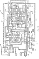
- Fig. 6 shows a configuration of control 20 for a second forward range in which trim system 30 applies main pressure to shift mechanism C4 via fluid chamber 144 of shift valve 36, passage 100, and fluid chamber 154 of shift valve 40. Main pressure is applied to shift mechanism C1 as described above with regard to Fig. 5 .
- Fig. 7 illustrates a configuration of control 20 for a fourth forward range in which main pressure is applied to shift mechanisms C1 and C2.
- Main pressure is applied to shift mechanism C1 as described above with regard to Fig. 5 .
- Main pressure is applied to shift mechanism C2 via fluid chamber 190 of shift valve 26, fluid passage 108, fluid chamber 136 of shift valve 38, fluid passage196, and fluid chamber 158 of shift valve 40.
- Fig. 7 also illustrates the application of torque converter clutch 14 by actuator 58, which by applying control pressure to the head of trim valve 34, connects main pressure from passage 116 with the torque converter clutch 14. Since main pressure flows through passage 116 in all of the normal modes of operation of control 20, torque converter clutch 14 can be actuated by actuator 58 at any time (i.e., in any range).
- Table 3 shows a steady state mechanization of components of control 20 in a failure mode resulting from an electrical failure.
- the number "1” is used to denote that a component is actuated, while the number “0” denotes that a component is not actuated.
- the letter “H” is used to indicate that a component is hydraulically held in position in the absence of electrical input.
- the mechanization of trim system 34 is omitted since the torque converter clutch 14 is not applied during an electrical failure.
- Figs. 8-13 show the configuration of control 20 in the event of an electrical failure in the Reverse 1, Reverse2, neutral, and first, second and fourth forward ranges in accordance with Table 3.
- Trim system 30 is actuated by a normally high solenoid and is therefore actuated in the event of an electrical failure.
- trim system 30 applies main pressure to either shift mechanism C5 or shift mechanism C3, depending on the position of shift valve 38, in the event of an electrical failure.
- trim system 30 When shift valve 38 is stroked during normal operation, trim system 30 is fluidly coupled to shift mechanism C5. This is the case in the Reverse1, neutral, and first forward ranges as shown in Figs. 2 , 4 and 5 . If an electrical failure occurs in one of these ranges, actuator 52 will not deliver pressure to shift valve 38 because of the absence of electrical input. However, the stroked position of shift valve 38 is maintained because trim system 30 applies main pressure to the differential area d3 of land 168 of shift valve 38 via fluid chamber 148. This is shown in Figs. 8 (Reverse1), 10 (neutral), and 11 (1 st forward range).
- the Reverse1 range fails to a neutral state in which the C5 shift mechanism is applied as shown in Fig. 8 .
- the Reverse2 range fails to a neutral state in which the C3 shift mechanism is applied as shown in Fig. 9 .
- the neutral range fails to the failure mode C5 neutral state shown in Fig. 10 .
- the failure mode C5 and C3 neutral states cannot be shifted out of as long as the electrical failure occurs, because shifting out of neutral to either a reverse range or forward range requires electrical input.
- Figs. 8 , 9 , and 10 also show how the flow of control pressure to the head of shift valve 40, via fluid chamber 140 of shift valve 36 and fluid passage 108, maintains the stroked position of shift valve 40 in the absence of electrical input to actuator 54.
- shift valve 40 When shift valve 40 is stroked, main pressure is blocked from entering passage 104, which is in fluid communication with shift valve 26.
- Figs. 11 , 12 , and 13 show failure mode configurations of control 20 for forward ranges.
- the first forward range is maintained in the event of an electrical failure due to the latching of shift valve 38 by pressure applied to the differential area of land 168, and the latching of shift valve 26.
- Pressure applied to the differential area of land 174 maintains the stroked position of shift valve 26 in the absence of electrical input to actuator 56.
- the second and third forward ranges fail to the third forward range in the event of an electrical failure, as shown in Fig. 12 .
- the shift valve 26 is latched as described above with reference to Fig. 11 .
- shift valve 38 is destroked in the second and third forward ranges. The destroked position is maintained in the event of electrical failure because the lands below land 168 have the same diameter as land 168.
- shift mechanism C3 is applied (if the failure occurred in the second forward range) or maintained (if the failure occurred in the third forward range) because the actuator for trim system 30 is of the normally high type.
- the fourth and higher forward ranges fail to the fifth forward range in the event of an electrical failure as shown in Fig. 13 .
- shift valve 26 is latched in the stroked position by pressure applied to the differential area of land 172.
- main pressure is supplied to shift mechanism C2 as described above with regard to Fig. 7 .
- Shift valve 40 is hydraulically latched by control pressure via passage 102 as described above.
- Trim system 30 applies main pressure to shift mechanism C3 because shift valve 38 is destroked.
- shift valve 26 In all forward ranges, the latching features on shift valve 26 in communication with shift mechanisms C1 and C2 as described above hold shift valve 26 in the stroked position as long as the transmission is receiving a forward range command from electrical control 22 or range selector 24, thereby providing protection against a mechanical failure of shift valve 26 that might otherwise cause shift valve 26 to erroneously move to the destroked position.
Landscapes
- Engineering & Computer Science (AREA)
- General Engineering & Computer Science (AREA)
- Mechanical Engineering (AREA)
- Control Of Transmission Device (AREA)
- Gear-Shifting Mechanisms (AREA)
Applications Claiming Priority (2)
| Application Number | Priority Date | Filing Date | Title |
|---|---|---|---|
| US12/510,487 US8371988B2 (en) | 2009-07-28 | 2009-07-28 | Electronically controlled range valve for multi-speed planetary transmission |
| PCT/US2010/040162 WO2011014326A1 (en) | 2009-07-28 | 2010-06-28 | Electronically controlled range valve for multi-speed planetary transmission |
Publications (3)
| Publication Number | Publication Date |
|---|---|
| EP2459904A1 EP2459904A1 (en) | 2012-06-06 |
| EP2459904A4 EP2459904A4 (en) | 2013-04-24 |
| EP2459904B1 true EP2459904B1 (en) | 2017-09-20 |
Family
ID=43527553
Family Applications (1)
| Application Number | Title | Priority Date | Filing Date |
|---|---|---|---|
| EP10804864.6A Not-in-force EP2459904B1 (en) | 2009-07-28 | 2010-06-28 | Electronically controlled range valve for multi-speed planetary transmission |
Country Status (7)
| Country | Link |
|---|---|
| US (3) | US8371988B2 (enExample) |
| EP (1) | EP2459904B1 (enExample) |
| KR (1) | KR101719017B1 (enExample) |
| CN (2) | CN104675987B (enExample) |
| CA (1) | CA2769058C (enExample) |
| IN (1) | IN2012DN01497A (enExample) |
| WO (1) | WO2011014326A1 (enExample) |
Families Citing this family (16)
| Publication number | Priority date | Publication date | Assignee | Title |
|---|---|---|---|---|
| US20090258756A1 (en) * | 2008-04-15 | 2009-10-15 | Long Charles F | Fly-by-wire control for multi-speed planetary transmission |
| US8371988B2 (en) | 2009-07-28 | 2013-02-12 | Allison Transmission, Inc. | Electronically controlled range valve for multi-speed planetary transmission |
| US8578802B2 (en) * | 2009-12-16 | 2013-11-12 | Allison Transmission, Inc. | System and method for multiplexing gear engagement control and providing fault protection in a toroidal traction drive automatic transmission |
| US8401752B2 (en) | 2009-12-16 | 2013-03-19 | Allison Transmission, Inc. | Fail-to-neutral system and method for a toroidal traction drive automatic transmission |
| DE102011017695B4 (de) * | 2011-04-28 | 2023-11-09 | Zf Friedrichshafen Ag | Vorrichtung zum Betätigen einer Getriebeeinrichtung mit mehreren elektrohydraulisch betätigbaren reib- und formschlüssigen Schaltelementen |
| JP5612624B2 (ja) * | 2012-03-08 | 2014-10-22 | 富士重工業株式会社 | レンジ切替装置 |
| US9399454B2 (en) * | 2014-11-21 | 2016-07-26 | GM Global Technology Operations LLC | Transmission with electronic range selector and pull out of park control logic |
| JP6660483B2 (ja) * | 2016-10-26 | 2020-03-11 | ジヤトコ株式会社 | 車両の制御装置及び車両の制御方法 |
| US10023190B2 (en) * | 2016-10-28 | 2018-07-17 | Ford Global Technologies, Llc | Method and control for operating a transmission in neutral |
| CN110651347B (zh) * | 2017-06-05 | 2021-08-27 | 阿尔卑斯阿尔派株式会社 | 推压式换档装置 |
| CN110892178B (zh) | 2017-06-30 | 2021-11-09 | 艾里逊变速箱公司 | 用于多级变速器的控制系统及其方法 |
| US10514094B2 (en) * | 2017-07-13 | 2019-12-24 | GM Global Technology Operations LLC | Method for controlling the internal electronic range selection for a 9 speed automatic transmission |
| GB201803286D0 (en) * | 2018-02-28 | 2018-04-11 | 3D Oscopy Ltd | Imaging system and method |
| CN109869477B (zh) * | 2019-03-28 | 2024-01-26 | 徐州徐工施维英机械有限公司 | 一种变速箱换档保护系统及工程机械 |
| US11181193B2 (en) * | 2019-11-27 | 2021-11-23 | Allison Transmission, Inc. | Power off hydraulic default strategy |
| CN113464639B (zh) * | 2021-06-09 | 2023-01-24 | 贵州大学 | 一种重型液力自动变速器的断电保护系统 |
Family Cites Families (22)
| Publication number | Priority date | Publication date | Assignee | Title |
|---|---|---|---|---|
| US4070927A (en) * | 1976-06-04 | 1978-01-31 | General Motors Corporation | Planetary gearing arrangement for a transmission |
| US4075912A (en) * | 1976-12-20 | 1978-02-28 | General Motors Corporation | Transmission with sump oil level responsive controls |
| JPS5642761A (en) * | 1979-09-10 | 1981-04-21 | Toyota Motor Corp | Oil pressure controller for automatic transmission |
| JP2689630B2 (ja) * | 1989-08-09 | 1997-12-10 | トヨタ自動車株式会社 | 車両用油圧クラッチの油圧制御装置 |
| JPH08184365A (ja) * | 1994-12-28 | 1996-07-16 | Nippon Soken Inc | 車両用自動変速装置 |
| US5601506A (en) * | 1995-10-13 | 1997-02-11 | General Motors Corporation | Electro-hydraulic control system in a power transmission |
| US5616093A (en) * | 1995-10-13 | 1997-04-01 | General Motors Corporation | Electro-hydraulic control system in a power transmission |
| US6319164B1 (en) * | 2000-05-23 | 2001-11-20 | General Motors Corporation | Electro-hydraulic control with a manual selection valve |
| KR100391411B1 (ko) * | 2000-12-30 | 2003-07-12 | 현대자동차주식회사 | 차량용 자동변속기의 유압 제어 시스템 |
| US6520881B1 (en) * | 2001-08-06 | 2003-02-18 | General Motors Corporation | Fly-by-wire electro-hydraulic control mechanism for a six speed transmission |
| US6585617B1 (en) * | 2001-12-19 | 2003-07-01 | General Motors Corporation | Electro-hydraulic control system for a multi-speed power transmission |
| US7140993B2 (en) * | 2004-10-28 | 2006-11-28 | General Motors Corporation | Fly-by-wire limp home and multi-plex system |
| US7288039B2 (en) * | 2005-10-31 | 2007-10-30 | General Motors Corporation | Multiplexed pressure switch system for an electrically variable hybrid transmission |
| US7396306B2 (en) | 2005-11-21 | 2008-07-08 | General Motors Corporation | Multiplexed control system and method for an electrically variable hybrid transmission |
| US7618344B2 (en) * | 2005-12-28 | 2009-11-17 | Aisin Aw Co., Ltd. | Hydraulic control apparatus for a multi-stage automatic transmission |
| US7510496B2 (en) * | 2006-06-06 | 2009-03-31 | General Motors Corporation | Electro-hydraulic control system with interlock protection |
| US7651427B2 (en) * | 2007-01-24 | 2010-01-26 | GM Global Trechnology Operations, Inc. | Electro-hydraulic control system with multiplexed pressure switch diagnostic system |
| US7736269B2 (en) * | 2007-02-14 | 2010-06-15 | Gm Global Technology Operations, Inc. | Electro-hydraulic control system with three-position dog clutch actuator valve |
| US8052563B2 (en) * | 2007-09-18 | 2011-11-08 | GM Global Technology Operations LLC | Electro-hydraulic control system for transmission with dual-area piston for torque-transmitting mechanism |
| US7980995B2 (en) * | 2007-09-18 | 2011-07-19 | GM Global Technology Operations LLC | Electro-hydraulic control system with multiplexed solenoid for retarder operation and main pressure modulation |
| KR100953307B1 (ko) * | 2007-11-06 | 2010-04-21 | 현대자동차주식회사 | 차량용 8속 자동 변속기의 유압 제어시스템 |
| US8371988B2 (en) * | 2009-07-28 | 2013-02-12 | Allison Transmission, Inc. | Electronically controlled range valve for multi-speed planetary transmission |
-
2009
- 2009-07-28 US US12/510,487 patent/US8371988B2/en not_active Expired - Fee Related
-
2010
- 2010-06-28 KR KR1020127004978A patent/KR101719017B1/ko active Active
- 2010-06-28 CN CN201410829773.0A patent/CN104675987B/zh active Active
- 2010-06-28 IN IN1497DEN2012 patent/IN2012DN01497A/en unknown
- 2010-06-28 WO PCT/US2010/040162 patent/WO2011014326A1/en not_active Ceased
- 2010-06-28 CA CA2769058A patent/CA2769058C/en active Active
- 2010-06-28 EP EP10804864.6A patent/EP2459904B1/en not_active Not-in-force
- 2010-06-28 CN CN201080042264.3A patent/CN102575763B/zh active Active
-
2013
- 2013-02-11 US US13/764,058 patent/US8858378B2/en active Active
-
2014
- 2014-10-14 US US14/514,022 patent/US9765877B2/en active Active
Non-Patent Citations (1)
| Title |
|---|
| None * |
Also Published As
| Publication number | Publication date |
|---|---|
| EP2459904A1 (en) | 2012-06-06 |
| CA2769058A1 (en) | 2011-02-03 |
| US20110028270A1 (en) | 2011-02-03 |
| US9765877B2 (en) | 2017-09-19 |
| US20130145883A1 (en) | 2013-06-13 |
| CN104675987B (zh) | 2018-04-06 |
| IN2012DN01497A (enExample) | 2015-06-05 |
| CA2769058C (en) | 2017-05-23 |
| WO2011014326A1 (en) | 2011-02-03 |
| US20150027259A1 (en) | 2015-01-29 |
| CN102575763A (zh) | 2012-07-11 |
| US8371988B2 (en) | 2013-02-12 |
| KR101719017B1 (ko) | 2017-03-22 |
| CN104675987A (zh) | 2015-06-03 |
| CN102575763B (zh) | 2015-01-21 |
| US8858378B2 (en) | 2014-10-14 |
| EP2459904A4 (en) | 2013-04-24 |
| KR20120048653A (ko) | 2012-05-15 |
Similar Documents
| Publication | Publication Date | Title |
|---|---|---|
| EP2459904B1 (en) | Electronically controlled range valve for multi-speed planetary transmission | |
| EP2401527B1 (en) | Electro-hydraulic failure recovery control for dual clutch transmission | |
| US8206254B2 (en) | Manual valve control for multi-speed planetary transmission | |
| US8894546B2 (en) | Electro-hydraulic control including blocking features for mulit-speed automatic transmission | |
| CN115978188B (zh) | 用于多级变速器的控制系统及其方法 |
Legal Events
| Date | Code | Title | Description |
|---|---|---|---|
| PUAI | Public reference made under article 153(3) epc to a published international application that has entered the european phase |
Free format text: ORIGINAL CODE: 0009012 |
|
| 17P | Request for examination filed |
Effective date: 20120216 |
|
| AK | Designated contracting states |
Kind code of ref document: A1 Designated state(s): AL AT BE BG CH CY CZ DE DK EE ES FI FR GB GR HR HU IE IS IT LI LT LU LV MC MK MT NL NO PL PT RO SE SI SK SM TR |
|
| DAX | Request for extension of the european patent (deleted) | ||
| A4 | Supplementary search report drawn up and despatched |
Effective date: 20130326 |
|
| RIC1 | Information provided on ipc code assigned before grant |
Ipc: F16H 61/02 20060101AFI20130320BHEP Ipc: F16H 61/12 20100101ALN20130320BHEP |
|
| 17Q | First examination report despatched |
Effective date: 20131206 |
|
| STAA | Information on the status of an ep patent application or granted ep patent |
Free format text: STATUS: EXAMINATION IS IN PROGRESS |
|
| RAP1 | Party data changed (applicant data changed or rights of an application transferred) |
Owner name: ALLISON TRANSMISSION, INC. |
|
| RIC1 | Information provided on ipc code assigned before grant |
Ipc: F16H 61/12 20100101ALN20170403BHEP Ipc: F16H 61/02 20060101AFI20170403BHEP |
|
| REG | Reference to a national code |
Ref country code: DE Ref legal event code: R079 Ref document number: 602010045433 Country of ref document: DE Free format text: PREVIOUS MAIN CLASS: F16H0061120000 Ipc: F16H0061020000 |
|
| GRAP | Despatch of communication of intention to grant a patent |
Free format text: ORIGINAL CODE: EPIDOSNIGR1 |
|
| STAA | Information on the status of an ep patent application or granted ep patent |
Free format text: STATUS: GRANT OF PATENT IS INTENDED |
|
| INTG | Intention to grant announced |
Effective date: 20170523 |
|
| RIC1 | Information provided on ipc code assigned before grant |
Ipc: F16H 61/12 20100101ALN20170515BHEP Ipc: F16H 61/02 20060101AFI20170515BHEP |
|
| GRAS | Grant fee paid |
Free format text: ORIGINAL CODE: EPIDOSNIGR3 |
|
| GRAA | (expected) grant |
Free format text: ORIGINAL CODE: 0009210 |
|
| STAA | Information on the status of an ep patent application or granted ep patent |
Free format text: STATUS: THE PATENT HAS BEEN GRANTED |
|
| AK | Designated contracting states |
Kind code of ref document: B1 Designated state(s): AL AT BE BG CH CY CZ DE DK EE ES FI FR GB GR HR HU IE IS IT LI LT LU LV MC MK MT NL NO PL PT RO SE SI SK SM TR |
|
| REG | Reference to a national code |
Ref country code: GB Ref legal event code: FG4D |
|
| REG | Reference to a national code |
Ref country code: CH Ref legal event code: EP |
|
| REG | Reference to a national code |
Ref country code: AT Ref legal event code: REF Ref document number: 930420 Country of ref document: AT Kind code of ref document: T Effective date: 20171015 |
|
| REG | Reference to a national code |
Ref country code: IE Ref legal event code: FG4D |
|
| REG | Reference to a national code |
Ref country code: DE Ref legal event code: R096 Ref document number: 602010045433 Country of ref document: DE |
|
| REG | Reference to a national code |
Ref country code: NL Ref legal event code: MP Effective date: 20170920 |
|
| PG25 | Lapsed in a contracting state [announced via postgrant information from national office to epo] |
Ref country code: SE Free format text: LAPSE BECAUSE OF FAILURE TO SUBMIT A TRANSLATION OF THE DESCRIPTION OR TO PAY THE FEE WITHIN THE PRESCRIBED TIME-LIMIT Effective date: 20170920 Ref country code: LT Free format text: LAPSE BECAUSE OF FAILURE TO SUBMIT A TRANSLATION OF THE DESCRIPTION OR TO PAY THE FEE WITHIN THE PRESCRIBED TIME-LIMIT Effective date: 20170920 Ref country code: FI Free format text: LAPSE BECAUSE OF FAILURE TO SUBMIT A TRANSLATION OF THE DESCRIPTION OR TO PAY THE FEE WITHIN THE PRESCRIBED TIME-LIMIT Effective date: 20170920 Ref country code: NO Free format text: LAPSE BECAUSE OF FAILURE TO SUBMIT A TRANSLATION OF THE DESCRIPTION OR TO PAY THE FEE WITHIN THE PRESCRIBED TIME-LIMIT Effective date: 20171220 Ref country code: HR Free format text: LAPSE BECAUSE OF FAILURE TO SUBMIT A TRANSLATION OF THE DESCRIPTION OR TO PAY THE FEE WITHIN THE PRESCRIBED TIME-LIMIT Effective date: 20170920 |
|
| REG | Reference to a national code |
Ref country code: LT Ref legal event code: MG4D |
|
| REG | Reference to a national code |
Ref country code: AT Ref legal event code: MK05 Ref document number: 930420 Country of ref document: AT Kind code of ref document: T Effective date: 20170920 |
|
| PG25 | Lapsed in a contracting state [announced via postgrant information from national office to epo] |
Ref country code: GR Free format text: LAPSE BECAUSE OF FAILURE TO SUBMIT A TRANSLATION OF THE DESCRIPTION OR TO PAY THE FEE WITHIN THE PRESCRIBED TIME-LIMIT Effective date: 20171221 Ref country code: LV Free format text: LAPSE BECAUSE OF FAILURE TO SUBMIT A TRANSLATION OF THE DESCRIPTION OR TO PAY THE FEE WITHIN THE PRESCRIBED TIME-LIMIT Effective date: 20170920 Ref country code: BG Free format text: LAPSE BECAUSE OF FAILURE TO SUBMIT A TRANSLATION OF THE DESCRIPTION OR TO PAY THE FEE WITHIN THE PRESCRIBED TIME-LIMIT Effective date: 20171220 |
|
| PG25 | Lapsed in a contracting state [announced via postgrant information from national office to epo] |
Ref country code: NL Free format text: LAPSE BECAUSE OF FAILURE TO SUBMIT A TRANSLATION OF THE DESCRIPTION OR TO PAY THE FEE WITHIN THE PRESCRIBED TIME-LIMIT Effective date: 20170920 |
|
| PG25 | Lapsed in a contracting state [announced via postgrant information from national office to epo] |
Ref country code: RO Free format text: LAPSE BECAUSE OF FAILURE TO SUBMIT A TRANSLATION OF THE DESCRIPTION OR TO PAY THE FEE WITHIN THE PRESCRIBED TIME-LIMIT Effective date: 20170920 Ref country code: PL Free format text: LAPSE BECAUSE OF FAILURE TO SUBMIT A TRANSLATION OF THE DESCRIPTION OR TO PAY THE FEE WITHIN THE PRESCRIBED TIME-LIMIT Effective date: 20170920 Ref country code: ES Free format text: LAPSE BECAUSE OF FAILURE TO SUBMIT A TRANSLATION OF THE DESCRIPTION OR TO PAY THE FEE WITHIN THE PRESCRIBED TIME-LIMIT Effective date: 20170920 Ref country code: CZ Free format text: LAPSE BECAUSE OF FAILURE TO SUBMIT A TRANSLATION OF THE DESCRIPTION OR TO PAY THE FEE WITHIN THE PRESCRIBED TIME-LIMIT Effective date: 20170920 |
|
| PG25 | Lapsed in a contracting state [announced via postgrant information from national office to epo] |
Ref country code: SK Free format text: LAPSE BECAUSE OF FAILURE TO SUBMIT A TRANSLATION OF THE DESCRIPTION OR TO PAY THE FEE WITHIN THE PRESCRIBED TIME-LIMIT Effective date: 20170920 Ref country code: IT Free format text: LAPSE BECAUSE OF FAILURE TO SUBMIT A TRANSLATION OF THE DESCRIPTION OR TO PAY THE FEE WITHIN THE PRESCRIBED TIME-LIMIT Effective date: 20170920 Ref country code: IS Free format text: LAPSE BECAUSE OF FAILURE TO SUBMIT A TRANSLATION OF THE DESCRIPTION OR TO PAY THE FEE WITHIN THE PRESCRIBED TIME-LIMIT Effective date: 20180120 Ref country code: EE Free format text: LAPSE BECAUSE OF FAILURE TO SUBMIT A TRANSLATION OF THE DESCRIPTION OR TO PAY THE FEE WITHIN THE PRESCRIBED TIME-LIMIT Effective date: 20170920 Ref country code: SM Free format text: LAPSE BECAUSE OF FAILURE TO SUBMIT A TRANSLATION OF THE DESCRIPTION OR TO PAY THE FEE WITHIN THE PRESCRIBED TIME-LIMIT Effective date: 20170920 Ref country code: AT Free format text: LAPSE BECAUSE OF FAILURE TO SUBMIT A TRANSLATION OF THE DESCRIPTION OR TO PAY THE FEE WITHIN THE PRESCRIBED TIME-LIMIT Effective date: 20170920 |
|
| REG | Reference to a national code |
Ref country code: DE Ref legal event code: R097 Ref document number: 602010045433 Country of ref document: DE |
|
| PLBE | No opposition filed within time limit |
Free format text: ORIGINAL CODE: 0009261 |
|
| STAA | Information on the status of an ep patent application or granted ep patent |
Free format text: STATUS: NO OPPOSITION FILED WITHIN TIME LIMIT |
|
| PG25 | Lapsed in a contracting state [announced via postgrant information from national office to epo] |
Ref country code: DK Free format text: LAPSE BECAUSE OF FAILURE TO SUBMIT A TRANSLATION OF THE DESCRIPTION OR TO PAY THE FEE WITHIN THE PRESCRIBED TIME-LIMIT Effective date: 20170920 |
|
| 26N | No opposition filed |
Effective date: 20180621 |
|
| PG25 | Lapsed in a contracting state [announced via postgrant information from national office to epo] |
Ref country code: SI Free format text: LAPSE BECAUSE OF FAILURE TO SUBMIT A TRANSLATION OF THE DESCRIPTION OR TO PAY THE FEE WITHIN THE PRESCRIBED TIME-LIMIT Effective date: 20170920 |
|
| REG | Reference to a national code |
Ref country code: CH Ref legal event code: PL |
|
| GBPC | Gb: european patent ceased through non-payment of renewal fee |
Effective date: 20180628 |
|
| REG | Reference to a national code |
Ref country code: BE Ref legal event code: MM Effective date: 20180630 |
|
| PG25 | Lapsed in a contracting state [announced via postgrant information from national office to epo] |
Ref country code: MC Free format text: LAPSE BECAUSE OF FAILURE TO SUBMIT A TRANSLATION OF THE DESCRIPTION OR TO PAY THE FEE WITHIN THE PRESCRIBED TIME-LIMIT Effective date: 20170920 Ref country code: LU Free format text: LAPSE BECAUSE OF NON-PAYMENT OF DUE FEES Effective date: 20180628 |
|
| REG | Reference to a national code |
Ref country code: IE Ref legal event code: MM4A |
|
| PG25 | Lapsed in a contracting state [announced via postgrant information from national office to epo] |
Ref country code: FR Free format text: LAPSE BECAUSE OF NON-PAYMENT OF DUE FEES Effective date: 20180630 Ref country code: LI Free format text: LAPSE BECAUSE OF NON-PAYMENT OF DUE FEES Effective date: 20180630 Ref country code: CH Free format text: LAPSE BECAUSE OF NON-PAYMENT OF DUE FEES Effective date: 20180630 Ref country code: IE Free format text: LAPSE BECAUSE OF NON-PAYMENT OF DUE FEES Effective date: 20180628 Ref country code: GB Free format text: LAPSE BECAUSE OF NON-PAYMENT OF DUE FEES Effective date: 20180628 |
|
| PG25 | Lapsed in a contracting state [announced via postgrant information from national office to epo] |
Ref country code: BE Free format text: LAPSE BECAUSE OF NON-PAYMENT OF DUE FEES Effective date: 20180630 |
|
| PG25 | Lapsed in a contracting state [announced via postgrant information from national office to epo] |
Ref country code: MT Free format text: LAPSE BECAUSE OF NON-PAYMENT OF DUE FEES Effective date: 20180628 |
|
| PG25 | Lapsed in a contracting state [announced via postgrant information from national office to epo] |
Ref country code: TR Free format text: LAPSE BECAUSE OF FAILURE TO SUBMIT A TRANSLATION OF THE DESCRIPTION OR TO PAY THE FEE WITHIN THE PRESCRIBED TIME-LIMIT Effective date: 20170920 |
|
| PG25 | Lapsed in a contracting state [announced via postgrant information from national office to epo] |
Ref country code: HU Free format text: LAPSE BECAUSE OF FAILURE TO SUBMIT A TRANSLATION OF THE DESCRIPTION OR TO PAY THE FEE WITHIN THE PRESCRIBED TIME-LIMIT; INVALID AB INITIO Effective date: 20100628 Ref country code: PT Free format text: LAPSE BECAUSE OF FAILURE TO SUBMIT A TRANSLATION OF THE DESCRIPTION OR TO PAY THE FEE WITHIN THE PRESCRIBED TIME-LIMIT Effective date: 20170920 |
|
| PG25 | Lapsed in a contracting state [announced via postgrant information from national office to epo] |
Ref country code: MK Free format text: LAPSE BECAUSE OF NON-PAYMENT OF DUE FEES Effective date: 20170920 Ref country code: CY Free format text: LAPSE BECAUSE OF FAILURE TO SUBMIT A TRANSLATION OF THE DESCRIPTION OR TO PAY THE FEE WITHIN THE PRESCRIBED TIME-LIMIT Effective date: 20170920 |
|
| PG25 | Lapsed in a contracting state [announced via postgrant information from national office to epo] |
Ref country code: AL Free format text: LAPSE BECAUSE OF FAILURE TO SUBMIT A TRANSLATION OF THE DESCRIPTION OR TO PAY THE FEE WITHIN THE PRESCRIBED TIME-LIMIT Effective date: 20170920 |
|
| P01 | Opt-out of the competence of the unified patent court (upc) registered |
Effective date: 20230526 |
|
| PGFP | Annual fee paid to national office [announced via postgrant information from national office to epo] |
Ref country code: DE Payment date: 20240627 Year of fee payment: 15 |
|
| REG | Reference to a national code |
Ref country code: DE Ref legal event code: R119 Ref document number: 602010045433 Country of ref document: DE |
|
| PG25 | Lapsed in a contracting state [announced via postgrant information from national office to epo] |
Ref country code: DE Free format text: LAPSE BECAUSE OF NON-PAYMENT OF DUE FEES Effective date: 20260101 |