EP2458519A1 - Method and apparatus of informing about a sensor mounting time period - Google Patents
Method and apparatus of informing about a sensor mounting time period Download PDFInfo
- Publication number
- EP2458519A1 EP2458519A1 EP11189990A EP11189990A EP2458519A1 EP 2458519 A1 EP2458519 A1 EP 2458519A1 EP 11189990 A EP11189990 A EP 11189990A EP 11189990 A EP11189990 A EP 11189990A EP 2458519 A1 EP2458519 A1 EP 2458519A1
- Authority
- EP
- European Patent Office
- Prior art keywords
- sensor
- informing
- living body
- time period
- standard time
- Prior art date
- Legal status (The legal status is an assumption and is not a legal conclusion. Google has not performed a legal analysis and makes no representation as to the accuracy of the status listed.)
- Withdrawn
Links
Images


Classifications
-
- G—PHYSICS
- G16—INFORMATION AND COMMUNICATION TECHNOLOGY [ICT] SPECIALLY ADAPTED FOR SPECIFIC APPLICATION FIELDS
- G16H—HEALTHCARE INFORMATICS, i.e. INFORMATION AND COMMUNICATION TECHNOLOGY [ICT] SPECIALLY ADAPTED FOR THE HANDLING OR PROCESSING OF MEDICAL OR HEALTHCARE DATA
- G16H40/00—ICT specially adapted for the management or administration of healthcare resources or facilities; ICT specially adapted for the management or operation of medical equipment or devices
- G16H40/20—ICT specially adapted for the management or administration of healthcare resources or facilities; ICT specially adapted for the management or operation of medical equipment or devices for the management or administration of healthcare resources or facilities, e.g. managing hospital staff or surgery rooms
-
- G—PHYSICS
- G16—INFORMATION AND COMMUNICATION TECHNOLOGY [ICT] SPECIALLY ADAPTED FOR SPECIFIC APPLICATION FIELDS
- G16H—HEALTHCARE INFORMATICS, i.e. INFORMATION AND COMMUNICATION TECHNOLOGY [ICT] SPECIALLY ADAPTED FOR THE HANDLING OR PROCESSING OF MEDICAL OR HEALTHCARE DATA
- G16H40/00—ICT specially adapted for the management or administration of healthcare resources or facilities; ICT specially adapted for the management or operation of medical equipment or devices
- G16H40/60—ICT specially adapted for the management or administration of healthcare resources or facilities; ICT specially adapted for the management or operation of medical equipment or devices for the operation of medical equipment or devices
- G16H40/63—ICT specially adapted for the management or administration of healthcare resources or facilities; ICT specially adapted for the management or operation of medical equipment or devices for the operation of medical equipment or devices for local operation
Definitions
- the present invention relates to a method of informing about a sensor mounting time period and an apparatus for informing about a sensor mounting time period.
- a biological information monitor collects biological information of a patient using sensors attached to the patient, processes the biological information as the information related to the patient's physical conditions, and converts it into a format including numerical values and the like, before transmitting the information to medical professionals such as doctors and nurses.
- the sensors of a biological information monitor are mounted on the patient's body under closely contacting conditions from the standpoint of maintaining best measurement accuracies at all times.
- maintaining a sensor in close contact for a prolonged period may cause pain due to pressure or a rash in the area of contact.
- a technology for mitigating the patient's burden by making the sensor more compact and lighter is disclosed in Japanese Unexamined Publication No. 2007-54594 .
- Japanese Unexamined Publication No. 2008-245701 disclose a technology of mitigating the burden caused by a localized pressure on a patient by applying a more uniform pressure in mounting a sensor on the patient's body.
- the present invention was made to solve the problems shown above.
- the object of the present invention is to provide a method and an apparatus for informing to medical professionals the elapsed time period during which a sensor communicating with the apparatus is mounted continuously on the patient's body, so that the sensor's mounting position is changed within the specified time interval.
- the method of informing the sensor mounting time period according to the present invention is to measure the time a sensor has been mounted on the living body for measuring biological information and issues a notification when the time reached a specified standard time.
- the sensor mounting time period informing apparatus is provided with detecting part, timer part, discriminating part, and informing part.
- the detecting part detects whether or not any sensor, communicating with the apparatus, is mounted on the living body for measuring biological information.
- the timer part counts the elapsed time period during which the sensor is continuously mounted on the living body based on the detection result of the detecting part.
- the discriminating part discriminates whether or not the elapsed time has reached the specified standard time.
- the informing part issues a notification when the elapsed time has reached the standard time based on the discrimination result of the discriminating part.
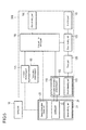
- Fig. 1 shows an outline block diagram for describing the apparatus for informing about a sensor mounting time period according to a first embodiment.
- the apparatus for informing about a sensor mounting time period is shown by the range surrounded by the chain line.
- the apparatus for informing about a sensor mounting time period is to notify that the duration of the time when a biological information sensor, which communicates with the apparatus, is mounted on the living body including patient's body, continuously has reached a specified standard time using the biological information measured by the sensor of the biological information monitor.
- the present embodiment will be described based mainly on a case of informing the sensor mounting time period of the pulse oximeter used as a biological information monitor.
- the pulse oximeter is a device for measuring oxygen saturation (S p O 2 ) of arterial blood continuously in a non-invasive manner.
- the biological information monitor herein is not limited to the pulse oximeter, but rather it is possible to constitute an apparatus for informing about a sensor mounting time period so long as the sensor of the biological information monitor other than the pulse oximeter is of a type that is mounted on the surface of a living body. Examples of applications to biological information monitors other than the pulse oximeter will be described later.
- an apparatus for informing about a sensor mounting time period 200 has a detecting part 100, a timer part 120, an discriminating part 130, an informing part 140, and a standard time setting part 150.
- the detecting part 100 has a biological information processing part 110 and a mount detecting part 115, and is connected to a sensor 20 by a cable or by a wireless device.
- Fig. 1 shows the relation between a living body 10 and the sensor 20 that detects the living body 10 by dotted lines.
- the sensor 20 is mounted on the living body 10 to measure biological information. More specifically, the sensor of the pulse oximeter, normally called a "probe" is mounted on a part of the surface of the living body (e.g., finger tip or forehead of the patient) to measure the transmitted light (transmission type probe) or reflected light (reflection type probe) of the light irradiated on the living body 10.
- the sensor 20 has a sensor affixing part 21, a sensing part 22, and a sensor information storage part 23.
- the sensor affixing part 21 affixes the sensing part 22 to the surface of the living body when mounting the sensor 20 on the living body 10. More specifically, the sensor affixing part 21 affixes the sensing part 22 in such a way to have the light emitting part and the light receiving part of the sensing part 22 placed in serial via the living body 10 in case of a transmission type probe. Also, it affixes the sensing part 22 in such a way as to have the illuminating part and the light receiving part of the sensing part 22 placed in parallel with the patient's body in case of a reflection type probe.
- the sensor affixing part 21 has various affixing devices including a clip type affixing device to pinch the patient's finger, an adhesive tape type affixing device to apply an adhesive tape on a patient's finger, a type which looks like a finger stall to be capped on a finger, etc., for the transmission type probe, and an adhesive type affixing device to be applied on the patient's forehead, etc., for the reflection type probe.
- a clip type affixing device to pinch the patient's finger
- an adhesive tape type affixing device to apply an adhesive tape on a patient's finger
- a type which looks like a finger stall to be capped on a finger, etc. for the transmission type probe
- an adhesive type affixing device to be applied on the patient's forehead, etc., for the reflection type probe.
- the sensing part 22 irradiates the living body 10 with a red light and an infrared light and receives the transmitted lights.
- the sensing part 22 is equipped with a light emitting part and a light receiving part, and is connected to the biological information processing part 110 of the detecting part 100.
- the light emitting part is equipped with a light emitting diode that emits lights with wave lengths in the neighborhood of 660 nm (red) and also 940 nm (infrared) and emits the lights onto a part of the surface of the living body such as finger tip.
- the light receiving part is equipped with, for example, a photo-diode to receive the light transmitted through blood vessels and living organisms, converts it to an electric current signal, and outputs it to the detecting part 100.
- the sensor information storage part 23 stores the type of the sensor 20. More specifically, the sensor information storage part 23 stores the information concerning the sensor 20 including the type of the sensor affixing part 21 and others in a memory element such as a resistor or a memory (ROM).
- the memory element is, for example, embedded in a sensor-side connector of the cable that connects the sensor 20 with the detecting part 100.
- the apparatus for informing about a sensor mounting time period 200 reads the information concerning the type of the sensor 20 stored in the sensor information storage part 23, and transmits it to the standard time setting part 150.
- the detecting part 100 detects whether the sensor 20 is mounted on the living body 10 or not.
- the detecting part 100 has a biological information processing part 110 and a mount detecting part 115, and is connected to the sensor 20 and the timer part 120.
- the biological information processing part 110 measures biological information to transmit it to the mount detecting part 115, and also processes the biological information to calculate the oxygen saturation of arterial blood.
- the mount detecting part 115 detects whether or not the sensor 20 is mounted on the living body 10 based on the biological information measured.
- biological information is information obtained biologically from the living body
- the fact that biological information is obtained by the biological information measuring part 110 means that the sensor 20 is mounted on the living body 10.
- the mount detecting part 115 generates a count-enable signal for clock operations and transmits it to the timer part 120.
- the mount detecting part 115 activates the clock-enabling signal.
- the mount detecting part 115 does not activate the clock-enabling signal.
- the timer part 120 counts the elapsed time period when the sensor 20 is continuously mounted on the living body 10 based on the detection result of the detecting part 100.
- the timer part 120 is connected to the detecting part 100 and the discriminating part 130.
- the timer part 120 starts timer as it receives the clock-enabling signal from the detecting part 100 and measures the time period during which the sensor 20 is continuously mounted on the living body 10.
- the timer part 120 is equipped with, for example, a digital counter that operates with a specified clock cycle, and starts counting time with the digital counter as it receives the clock-enabling signal.
- the timer part 120 transmits the duration time period that corresponds with the count value to the discriminating part 130.
- the timer part 120 continues the counting operation even during a period when the mounted sensor 20 is temporarily (e.g., less than 1 second) is removed from the living body 10 and the biological information is not measured temporarily. In other words, it treats the temporary removal of the sensor 20 from the living body 10 as if the sensor 20 is continuously mounted on the living body 10. On the other hand, if it is judged that the removal of the sensor 20 is not temporary, it resets the digital counter and waits for the sensor 20 to be mounted again on the living body 10.
- temporarily e.g., less than 1 second
- the timer can also be started when a medical professional operates a timer start key (not shown). Consequently, the mounting start time of the sensor 20 can be more securely determined.
- the discriminating part 130 discriminates whether or not the elapsed time period during which the sensor 20 is mounted continuously on the living body 10 has reached the specified standard time.
- the discriminating part 130 is connected to the timer part 120 and the informing part 140.
- the discriminating part 130 generates the standard time reaching signal for informing whether or not the elapsed time period has reached the standard time and transmits it to the informing part 140.
- the discriminating part 130 activates the standard time reaching signal when the elapsed time period received from the timer part 120 reaches the standard time. On the other hand, the discriminating part 130 does not activate the standard time reaching signal when the elapsed time period has not reached the standard time.
- the informing part 140 issues a notification based on the discrimination result of the discriminating part 130 when the elapsed time has reached the standard time. More specifically, the informing part 140 is connected to the discriminating part 130 and executes the informing action upon receiving the standard time reaching signal from the discriminating part 130.
- the informing part 140 is equipped with, e.g., a speaker, lamp, monitor display, etc., and is capable of informing by an alarm sound, voice message, light, optical message, etc., upon receiving the standard time reaching signal from the discriminating part 130. Moreover, the informing part 140 is equipped with a communication device so that it is also capable of informing a medical professional at a central control center located at a distance from the patient's current position.
- the standard time setting part 150 is connected to the sensor information storage part 23 and the discriminating part 130, generates the standard time and transmits it to the discriminating part 130.
- the standard time is the time determined depending on the type of the sensor 20 based on the time period during which the sensor 20 can be mounted at the same location of the surface of the living body continuously.
- the type of the sensor 20 is reported to the standard time setting part 150 by the sensor information storage part 23 of the sensor 20.
- the type of the sensor 20 depends on, e.g., the type of the sensor affixing part 21.
- the standard time setting part 150 can set the standard time depending on the type of the sensor affixing part 21.
- the standard time setting part 150 sets, for example, the standard time as 4 hours when the sensor affixing part 21 is a clip-style affixing device, or 8 hours when the sensor affixing part 21 is an adhesive-type affixing device.
- the setting of the standard time depending on the type of the sensor affixing part 21 can be arbitrarily changed.
- the detecting part 100 has a biological information processing part 110 and a mount detecting part 115.
- the biological information processing part 110 has a light emission control part 111, a demodulation part 112, light absorbance ratio calculation part 113, and an oxygen saturation calculation part 114, transmits biological information to the mount detecting part 115, and calculates the oxygen saturation of arterial blood by processing the biological information.
- the light emission control part 111 controls the timing of illumination of a light emitting part 22a of the sensing part 22. More specifically, the light emission control part 111 generates a light emission timing signal and controls it in such a manner that a red light-emitting diode and a infrared light-emitting diode illuminates reciprocally at a given timing.
- the modulation part 112 generates red transmitted light signals and infrared transmitted light signals. More specifically, the demodulation part 112 converts electric current signals generated by a light-receiving part 22b of the sensing part 22 into electric voltage signals, and then generates red transmitted light signals and infrared transmitted light signals by demodulating the electric voltage signals using the light emission timing signals generated by the light emission control part 111.
- the red lights and the infrared lights entering the living body 10 from the light-emitting part 22a are received by the light-receiving part 22b after passing through body tissues, venous blood and arterial blood.
- the transmitted light signal weakens when the blood flow volume in the artery increases as the patient's heart contracts, while the transmitted light signal strengthens when the blood flow volume in the artery reduces as the heart expands. Therefore, the transmitted light varies with the variation of the blood flow volume in the artery due to the pulsation of the heart.
- the light absorbance ratio calculation part 113 calculates the ratio between the light absorbance of the red light and the infrared light.
- the transmitted light signal generated in the demodulation part 112 appears in a wavy form in which an AC component (pulsation component) is superimposed on a DC component.
- the light absorbance ratio calculation part 113 separates the DC component and the AC component for each of the red transmitted light signal and the infrared transmitted signal and calculates pulsation ratios (AC component/DC component).
- the light absorbance ratio calculation part 113 calculates an approximate ratio between the absorbances of the red light and the infrared light by calculating the ratio of the pulsation rate of the red light and the pulsation rate of the infrared light.
- the oxygen saturation calculation part 114 calculates the arterial blood oxygen saturation of hemoglobin from the ratio between the red light and the infrared light. As to the process of this calculation, it is similar to the calculation process in the pulse oximeter of the prior art so that detailed explanation is omitted here.
- the calculated arterial blood oxygen saturation is displayed on a display device not shown here.
- the mount detecting part 115 detects whether or not the sensor 20 is mounted on the living body based on the biological information signal received from the biological information processing part 110. More specifically, the mount detecting part 115 is connected to the demodulation part 112 of the biological information processing part 110, and detects whether or not the sensor 20 is mounted on the living body 10 using the transmitted light signal generated by the demodulation part 112. The method of detecting whether or not the sensor 20 is mounted on the living body 10 using the transmitted light signal is described below with reference to Fig. 3 .
- Fig. 3 is a waveform diagram showing a chronological change of transmitted light signals emitted from the demodulation part 112 shown in Fig. 2 .
- the vertical axis of Fig. 3 represents the intensity of the transmitted light signal and the horizontal axis represents the elapsed time.
- Fig. 3 shows the transmitted light signal outputted from the demodulation part 112 when the living body 10 is irradiated with red light and infrared light, and the transmitted light signal reflect the pulse waves of the red light and the infrared light.
- the pulse waves measured for the red light and the infrared light will be denoted as the pulse wave 1 and the pulse wave 2.
- the DC component DC 2 of the transmitted light signal of the pulse wave 2 is shown larger than the maximum valued of the transmitted light signal of the pulse wave 1 for the convenience of drawing the pulse wave 1 and the pulse wave 2.
- the DC components DC 1 and DC 2 of the transmitted light signals of the pulse wave 1 and the pulse wave 2 depend on the thickness of body tissue and the amount of venous blood, while the amplitudes A1 and A2 depend on the degree of combination between hemoglobin and oxygen in the arterial blood.
- the DC components DC 1 and DC 2 of the pulse wave 1 and the pulse wave 2 assume values within their respective specified ranges.
- the specified position of the living body 10 here means the part of a relatively thin tissue of the living body 10, for example, the finger tip.
- the DC components DC 1 and DC 2 assumes the values between the upper threshold value I UTh and the lower threshold I LTh of the transmitted light signal intensity, the DC components DC 1 and DC 2 lie within the specified ranged.
- the DC components DC 1 and DC 2 do not assume the values between the upper threshold value I UTh and the lower threshold I LTh , the DC components DC 1 and DC 2 do not lie within the specified ranged. In this case, there is a probability that the sensor 20 may not be properly mounted at the specified position of the living body 10.
- the DC components DC 1 or DC 2 is greater than the upper threshold value I UTh , there is a possibility that the finger tip is not properly inserted between the light-emitting part 22a and the light-receiving part 22b of the sensor 20, so that the light from the light-emitting part may be directly transmitted to the light-receiving part 22b.
- the DC components DC 1 or DC 2 is smaller than the lower threshold I LTh , there is a possibility that the sensor 20 is removed from the finger tip, or the sensor 20 is mounted on a living body part thicker than the finger tip, so that the light may not be transmitted between the light-emitting part 22a and the light-receiving part 22b of the sensor 20.
- the amplitudes A 1 and A 2 of the pulse wave 1 and the pulse wave 2 assume values within the specified range depending on the degree of combination between hemoglobin and oxygen within arterial blood.
- the specified range herein can be arbitrarily determined based on the degree of combination between hemoglobin and oxygen and the relation between the transmitted red light and infrared light of the living body.
- the amplitudes A 1 and A 2 are not values within the specified range, there is a possibility that the sensor 20 may not be properly mounted at the specified position of the living body 10.
- the intervals T 1 and T 2 of the pulse wave 1 and the pulse wave 2 may assume values within the specified range in correspondence with the change of the volume of the arterial blood.
- the intervals T 1 and T 2 are not values within the specified range, there is a possibility that the sensor 20 may not be properly mounted at the specified position of the living body 10.
- amplitudes and intervals other items such as the rising time or shape of the pulse wave can be added as the judgment conditions.
- the ratio between the transmitted light and the incident light can be used instead of the absolute value of the transmitted light as the transmitted light signal.
- the detecting part 100 activates the clock-enabling signal.
- the detecting part 100 does not activate the clock-enabling signal.
- the elapsed time period during which the sensor 20 is mounted continuously on the living body 10 is measured based on the detection result of whether the sensor 20 is mounted on the living body 10. More specifically, the timer part 120 starts timer as it receives the clock-enabling signal from the detecting part 100 and measures the elapsed time period during which the sensor 20 is continuously mounted on the living body 10.
- the discriminating part 130 activates the standard time reaching signal when the elapsed time period received from the timer part 120 reaches the standard time. On the other hand, the discriminating part 130 does not activate the standard time reaching signal when the elapsed time period has not reached the standard time.
- a notification that the elapsed time has reached the standard time is issued based on discrimination result of the discriminating part 130. More specifically, the informing part 140 receives the standard time reaching signal from the discriminating part 130 and notifies medical professionals with an alarm sound, voice, light or visual message.
- Fig. 4 shows a flowchart for describing the method of informing about a sensor mounting time period according to the embodiment.
- the method of informing the sensor mounting time period is to measure the time a sensor has been mounted continuously on the living body for measuring biological information and issues a notification when the time reached a specified standard time.
- step S101 a judgment is made as to whether or not the sensor communicating with the apparatus is mounted on the living body (step S101). If it is confirmed that the sensor communicating with the apparatus is mounted on the living body (steps S101: YES), the program advances to the next step S102. On the other hand, if it is not confirmed that the sensor communicating with the apparatus is mounted on the living body (steps S101: NO), the program awaits for the sensor to be mounted on the living body.
- step S102 the elapsed time period during which a sensor communicating with the apparatus is mounted continuously on the living body is measured.
- step S103 a judgment is made as to whether or not the elapsed time has reached the specified standard time.
- step S 103: YES the program advances to the next step S 104.
- step S103: NO the program awaits until the elapsed time reaches the specified standard time.
- the configuration of the pulse oximeter as the biological information monitor for informing the sensor mounting time period has been described.
- the configurations of biological information monitors other than the pulse oximeter for informing the sensor mounting time period will be described below.
- the apparatuses for informing about a sensor mounting time period described below are different from the apparatus for informing about a sensor mounting time period based on the pulse oximeter only in the configurations of the detecting part and the sensor. Therefore, only the configurations of the detecting part and the sensor are explained and the configurations of other parts will be omitted in the following descriptions.
- the apparatus for informing about a sensor mounting time period using the electrocardiograph uses a plurality of electrodes in its sensing part of the sensor.
- the electrodes are affixed to the living body with the sensor affixing part including adhesive tapes and the cardiogram signals from the electrodes are transmitted to the biological information processing part of the detecting part.
- the biological information processing part amplifies the cardiograph signals, extracts cardiogram waveforms, and transmits them to the mount detecting part.
- the part that measures and processes the cardiogram waveforms in the biological information processing part is similar to that of the conventional cardiograph, so that its description is omitted here.
- the mount detecting part measures the cardiogram waveforms extracted by the biological information processing part to obtain amplitudes and intervals, determines whether or not the sensor communicating with the apparatus is mounted on the living body based on whether or not the measured values are within the specified ranges.
- the shapes of the cardiogram waveforms can be used as an additional condition in the judgment as well.
- the apparatus for informing about a sensor mounting time period using the electroencephalograph uses a plurality of electrodes in its sensing part of the sensor.
- the electrodes are typically made as needle electrodes or dish electrodes and are affixed by the sensor affixing part including adhesive tapes or cap-lie affixing equipment.
- the electroencephalogram signals from the electrodes are transmitted to the biological information processing part of the detecting part.
- the biological information processing part amplifies the electroencephalogram signals, extracts electroencephalogram waveforms, and transmits them to the mount detecting part.
- the part that measures and processes the electroencephalogram waveforms in the biological information processing part is similar to that of the conventional electroencephalograph, so that its description is omitted here.
- the mount detecting part measures the electroencephalogram waveforms extracted by the biological information processing part to obtain amplitudes and intervals, determines whether or not the sensor communicating with the apparatus is mounted on the living body based on whether or not the measured values are within the specified ranges. Moreover, the rising times and shapes of the electroencephalogram waveforms can be used as additional conditions in the judgment as well.
- the apparatus for informing about a sensor mounting time period using the clinical thermometer uses a thermister in its sensing part of the sensor.
- the thermister is affixed to the living body with the sensor affixing part including adhesive tapes and the body temperature from the thermister is transmitted after converting it an electrical signal to the biological information processing part of the detecting part.
- the biological information processing part measures the body temperature and transmits it to the mount detecting part.
- the part that measures and processes the body temperature in the biological information processing part is similar to that of the conventional clinical thermometer, so that its description is omitted here.
- the mount detecting part detects whether or not the sensor communicating with the apparatus is mounted on the living body based on the measured body temperature is within the specified range.
- the apparatus for informing about a sensor mounting time period using the phonocardiograph uses a microphone in its sensing part of the sensor.
- the microphone is affixed to the living body with the sensor affixing part including adhesive tapes and the phonocardiogram is transmitted after converting it an electrical signal to the biological information processing part of the detecting part.
- the biological information processing part after amplifying and wave-filtering the transmitted electrical signal, extracts only the sound from the heart, and transmits it as the phonocardiogram signal to the mount detecting part.
- the part that measures and processes the phonocardiogram in the biological information processing part is similar to that of the conventional phonocardiograph, so that its description is omitted here.
- the mount detecting part measures the phonocardiogram signal extracted by the biological information processing part to obtain DC components, amplitudes and intervals, determines whether or not the sensor communicating with the apparatus is mounted on the living body based on whether or not the measured values are within the specified ranges.
- the rising times and shapes of the phonocardiogram signals can be used as additional conditions in the judgment as well.
- the apparatus for informing about a sensor mounting time period using the percutaneous gas monitor uses a percutaneous gas sensor in its sensing part of the sensor.
- the percutaneous gas sensor is affixed to the living body with the sensor affixing part including adhesive tapes and the gas collected from the body surface by sampling is transmitted to the biological information processing part of the detecting part.
- the biological information processing part analyzes the transmitted gas components, converts the analysis result to an electrical signal and transmits it as a gas component signal to the mount detecting part.
- the mount detecting part detects whether or not the sensor communicating with the apparatus is mounted on the living body based on whether or not the specified amount of the gas component of the measurement target exists.
- NIBP Non-invasive blood pressure
- the apparatus for informing about a sensor mounting time period using the NIBP monitor uses a cuff that serves both as the sensing part and the affixing part of the sensor.
- the pressure and the pressure pulse wave accompanying the cardiac motion are detected inside the cuff wrapped around the patient's arm.
- the pressure sensor converts the pressure and the pressure pulse wave into electrical signals and transmits them to the biological information processing part of the detecting part.
- the biological information processing part extracts the cuff pressure and pressure pulse wave, and transmits them as the cuff pressure signal and the pressure pulse wave signal to the mount detecting part.
- the part that measures the blood pressure in the biological information processing part is similar to that of the conventional NIBP monitor, so that its description is omitted here.
- the mount detecting part measures the pulse wave signal extracted by the biological information processing part to obtain DC components, amplitudes and intervals, determines whether or not the sensor communicating with the apparatus is mounted on the living body based on whether or not the measured pulse wave signal and cuff pressure values are within the specified ranges. Moreover, the rising times and shapes of the pulse wave signal can be used as additional conditions in the judgment as well.
- the apparatus for informing about a sensor mounting time period detects whether or not the sensor communicating with the apparatus is mounted on the living body, and measures the elapsed time period during which a sensor communicating with the apparatus is mounted continuously on the living body based on the detection result. It then makes a judgment as to whether or not the elapsed time period has reached the specified standard time, and reports that the elapsed time period has reached the standard time base on the detection result.
- the standard time setting part is connected to the sensor information storing part and the discriminating part, and the standard time is set in accordance with the type of the sensor.
- Fig. 5 shows an outline block diagram for describing the apparatus for informing about a sensor mounting time period according to a second embodiment.
- the apparatus 200 for informing about a sensor mounting time period according to the present embodiment further has a temperature measuring part 160, a pressure measuring part 170, and a manual setting part 180 in addition to the configuration of the apparatus 200 for informing about a sensor mounting time period according to the first embodiment.
- the standard time setting part 150 is further connected to the biological information processing part 110, the temperature measuring part 160, the pressure measuring part 170, and the manual setting part 180 in addition to the sensor information storing part 23 and the discriminating part 130.
- the temperature measuring part 160 directly or indirectly measures the temperature of the contact area between the living body 10 and the sensor 20. If it is desired to measure the body temperature directly, it is achieved by causing the sensor 20 to contact with the surface of the living body 10 directly.
- the temperature of the contact area can be estimated by measuring the forward direction voltage in case the light-emitting part is a light-emitting diode.
- the pressure measuring part 170 directly or indirectly measures the pressure of the contact area between the living body 10 and the sensor 20. If it is desired to measure the contact pressure of the sensor 20 against the living body 10 directly, it is achieved by causing a pressure sensor to contact on the surface of the living body to measure the pressure of the contact area between the living body 10 and the sensor 20.
- the standard time setting can be done as follows.
- the standard time can be set in accordance with at least one of the items: the type of the sensor 20, biological information, the temperature of the contact area between the living body 10 and the sensor 20, and the contact pressure between the sensor 20 and the living body 10.
- the standard time can be set up by medical professionals preferentially and directly in a manual mode.
- the standard time can be set up using the measured biological information as follows;
- the biological information is transmitted from the biological information processing part 110 to the standard time setting part 150.
- the standard time setting part 150 can set the standard time based on the biological information processing result received from the biological information processing part 110. For example, even if the same sensor is used, there is a chance that the mounting position may need to be changed earlier than the normal standard depending on the patient's condition.
- the standard time setting part 150 can set up the standard time shorter than usual, if the amplitude of the pulse wave measured by the biological information processing part 110 is extremely small and does not meet the specified value. Also, the standard time setting part 150 can set up the standard time shorter than usual in correspondence with the cardiac rate, if the cardiac rate is extremely high or extremely low.
- the standard time can be set up using the measured temperature as follows;
- the temperature of the contact area between the living body 10 and the sensor 20 is transmitted as the temperature measuring result from the temperature measuring part 160 to the standard time setting part 150.
- the standard time setting part 150 can set up the standard time based on the temperature measuring result received from the temperature measuring part 160.
- the standard time setting part 150 can be equipped with the compensation device.
- the compensation device compensates, for example, in such a way that the higher the measured temperature, the shorter the standard time. Consequently, if the temperature of the contact area between the living body 10 and the sensor 20 is high, the standard time is set shorter. As a result, the burden of the patient on the skin due to the heat of the light-emitting part can be reduced.
- the standard time setting part 150 can set the standard time between 0 and several seconds if the measured temperature exceeds the specified temperature. As a result, the discriminating part 130 can issue the standard time reaching signal instantaneously. Therefore, if the temperature of the contact area between the living body 10 and the sensor 20 is higher than the specified value, it is possible to take an emergency measure of causing the system to be shut down immediately or to shift its condition safer for the patient.
- the standard time can be set up using the measured contact pressure as follows;
- the contact pressure between the living body 10 and the sensor 20 is transmitted as the contact pressure result from the pressure measuring part 170 to the standard time setting part 150.
- the standard time setting part 150 can set up the standard time based on the pressure measuring result received from the pressure measuring part 170.
- the standard time setting part 150 can be equipped with the compensation device.
- the compensation device compensates, for example, in such a way that the higher the measured pressure, the shorter the standard time. Consequently, if the contact pressure between the living body 10 and the sensor 20 is high, the standard time is set shorter. As a result, it is possible to prevent an excessive contact pressure from being applied to the patient's skin by the sensor 20 for a prolonged period of time.
- the standard time setting part 150 can set the standard time between 0 and several seconds if the measured contact pressure exceeds the specified value. As a result, the discriminating part 130 can issue the standard time reaching signal instantaneously. Therefore, if the contact pressure between the living body 10 and the sensor 20 is higher than the specified value, it is possible to take an emergency measure of causing the system to be shut down immediately or to shift its condition safer for the patient.
- the standard time can be set up directly by a medical professional in a manual mode as follows:
- the standard time setting part 150 can set up the standard time based on the manual setting information received from the manual setting part 180.
- the manual setting part 180 is equipped with, for example, an input keyboard, a touch panel, etc.
- the standard time setting part 150 can set up the standard time based on the manual setting information entered by a medical professional via the manual setting part 180.
- the manual setting information can be information related to the patient's physical condition in addition to the value corresponding to the standard time.
- the standard time can be set in accordance with at least one of the items: the type of the sensor 20, biological information, the temperature of the contact area between the living body 10 and the sensor 20, and the contact pressure between the sensor 20 and the living body 10.
- the standard time can be set up by medical professionals preferentially and directly in a manual mode.
- the present embodiment provides the following effects in addition to the effects provided by the first embodiment.
- the configuration of the apparatus for informing about a sensor mounting time period is such that the notification is issued using the biological information monitors, e.g., pulse oximeter, electrocardiograph, electroencephalograph, clinical thermometer, phonocardiograph, percutaneous gas monitor, and NIBP monitor.
- the biological information monitor applicable is not limited to the abovementioned biological information monitor, but rather any other types of sensors such as a respiratory sound measuring device, electromyograph, tissue oximeter, etc., can be used to configure the apparatus for informing about a sensor mounting time period so long as they can be affixed on the living body surface.
- the standard time is adjusted using at least one kind of information from the group; type of the sensor, temperature measurement result, pressure measurement result, biological information measurement result, and manual setup information.
- type of the sensor type of the sensor
- temperature measurement result temperature measurement result
- pressure measurement result pressure measurement result
- biological information measurement result biological information measurement result
- manual setup information manual setup information
- the mounting of the sensor on the living body can be identified so long as the temperature and/or the pressure falls within the specified ranges.
Applications Claiming Priority (1)
| Application Number | Priority Date | Filing Date | Title |
|---|---|---|---|
| JP2010262486A JP5426521B2 (ja) | 2010-11-25 | 2010-11-25 | センサ装着時間報知方法および装置 |
Publications (1)
| Publication Number | Publication Date |
|---|---|
| EP2458519A1 true EP2458519A1 (en) | 2012-05-30 |
Family
ID=45346238
Family Applications (1)
| Application Number | Title | Priority Date | Filing Date |
|---|---|---|---|
| EP11189990A Withdrawn EP2458519A1 (en) | 2010-11-25 | 2011-11-21 | Method and apparatus of informing about a sensor mounting time period |
Country Status (4)
| Country | Link |
|---|---|
| US (1) | US20120136228A1 (ja) |
| EP (1) | EP2458519A1 (ja) |
| JP (1) | JP5426521B2 (ja) |
| CN (1) | CN102551734A (ja) |
Cited By (1)
| Publication number | Priority date | Publication date | Assignee | Title |
|---|---|---|---|---|
| JP2012110520A (ja) * | 2010-11-25 | 2012-06-14 | Nippon Koden Corp | センサ装着時間報知方法および装置 |
Families Citing this family (11)
| Publication number | Priority date | Publication date | Assignee | Title |
|---|---|---|---|---|
| TWI555403B (zh) * | 2013-06-20 | 2016-10-21 | 晨星半導體股份有限公司 | 電視控制方法與相關之電視 |
| JP5739507B2 (ja) * | 2013-11-25 | 2015-06-24 | 日本光電工業株式会社 | センサ装着時間報知装置 |
| US10588555B2 (en) | 2014-05-20 | 2020-03-17 | Pioneer Corporation | Pulse oximeter |
| CN105163180A (zh) * | 2015-08-21 | 2015-12-16 | 小米科技有限责任公司 | 播放控制方法、装置及终端 |
| WO2017119130A1 (ja) * | 2016-01-08 | 2017-07-13 | 株式会社三菱ケミカルホールディングス | 非侵襲型生体脂質計測器及び非侵襲型生体脂質計測方法 |
| JP6712773B2 (ja) * | 2016-03-08 | 2020-06-24 | パナソニックIpマネジメント株式会社 | 生体信号検知装置 |
| JP2021006071A (ja) * | 2017-09-20 | 2021-01-21 | アルプスアルパイン株式会社 | 生体情報測定装置 |
| JP6989401B2 (ja) * | 2018-02-06 | 2022-01-05 | 株式会社日立製作所 | 生体情報利用管理システムおよび生体情報利用管理方法 |
| JP2019048050A (ja) * | 2018-09-03 | 2019-03-28 | パイオニア株式会社 | パルスオキシメータ |
| JP2021007783A (ja) * | 2020-10-13 | 2021-01-28 | パイオニア株式会社 | パルスオキシメータ |
| JP7257571B2 (ja) * | 2020-10-13 | 2023-04-13 | エア・ウォーター・バイオデザイン株式会社 | パルスオキシメータ |
Citations (2)
| Publication number | Priority date | Publication date | Assignee | Title |
|---|---|---|---|---|
| JP2007054594A (ja) | 2005-07-29 | 2007-03-08 | Nippon Koden Corp | パルスオキシメータ用プローブ |
| JP2008245701A (ja) | 2007-03-29 | 2008-10-16 | Nippon Koden Corp | 装着バンド及び生体信号測定用プローブの生体への装着方法。 |
Family Cites Families (9)
| Publication number | Priority date | Publication date | Assignee | Title |
|---|---|---|---|---|
| JPH0366358A (ja) * | 1989-08-03 | 1991-03-22 | Terumo Corp | 生体信号計測装置 |
| US6035223A (en) * | 1997-11-19 | 2000-03-07 | Nellcor Puritan Bennett Inc. | Method and apparatus for determining the state of an oximetry sensor |
| JP4327825B2 (ja) * | 2000-03-14 | 2009-09-09 | 株式会社東芝 | 身体装着型生活支援装置および方法 |
| US6606510B2 (en) * | 2000-08-31 | 2003-08-12 | Mallinckrodt Inc. | Oximeter sensor with digital memory encoding patient data |
| CN101803907B (zh) * | 2005-09-21 | 2015-02-18 | 杨章民 | 电子装置 |
| US8092379B2 (en) * | 2005-09-29 | 2012-01-10 | Nellcor Puritan Bennett Llc | Method and system for determining when to reposition a physiological sensor |
| US8352004B2 (en) * | 2007-12-21 | 2013-01-08 | Covidien Lp | Medical sensor and technique for using the same |
| WO2009124077A1 (en) * | 2008-03-31 | 2009-10-08 | Nellcor Puritan Bennett Llc | Detection of site oximetry degradation |
| JP5426521B2 (ja) * | 2010-11-25 | 2014-02-26 | 日本光電工業株式会社 | センサ装着時間報知方法および装置 |
-
2010
- 2010-11-25 JP JP2010262486A patent/JP5426521B2/ja active Active
-
2011
- 2011-10-31 US US13/285,112 patent/US20120136228A1/en not_active Abandoned
- 2011-11-21 EP EP11189990A patent/EP2458519A1/en not_active Withdrawn
- 2011-11-23 CN CN2011103818066A patent/CN102551734A/zh active Pending
Patent Citations (2)
| Publication number | Priority date | Publication date | Assignee | Title |
|---|---|---|---|---|
| JP2007054594A (ja) | 2005-07-29 | 2007-03-08 | Nippon Koden Corp | パルスオキシメータ用プローブ |
| JP2008245701A (ja) | 2007-03-29 | 2008-10-16 | Nippon Koden Corp | 装着バンド及び生体信号測定用プローブの生体への装着方法。 |
Non-Patent Citations (2)
| Title |
|---|
| "STATEMENT IN ACCORDANCE WITH THE NOTICE FROM THE EUROPEAN PATENT OFFICE DATED 1 OCTOBER 2007 CONCERNING BUSINESS METHODS - EPC / ERKLAERUNG GEMAESS DER MITTEILUNG DES EUROPAEISCHEN PATENTAMTS VOM 1.OKTOBER 2007 UEBER GESCHAEFTSMETHODEN - EPU / DECLARATION CONFORMEMENT AU COMMUNIQUE DE L'OFFICE EUROP", 20071101, 1 November 2007 (2007-11-01), XP002456252 * |
| EPO: "Mitteilung des Europäischen Patentamts vom 1. Oktober 2007 über Geschäftsmethoden = Notice from the European Patent Office dated 1 October 2007 concerning business methods = Communiqué de l'Office européen des brevets,en date du 1er octobre 2007, concernant les méthodes dans le domaine des activités", JOURNAL OFFICIEL DE L'OFFICE EUROPEEN DES BREVETS.OFFICIAL JOURNAL OF THE EUROPEAN PATENT OFFICE.AMTSBLATTT DES EUROPAEISCHEN PATENTAMTS, OEB, MUNCHEN, DE, vol. 30, no. 11, 1 November 2007 (2007-11-01), pages 592 - 593, XP002498048, ISSN: 0170-9291 * |
Cited By (1)
| Publication number | Priority date | Publication date | Assignee | Title |
|---|---|---|---|---|
| JP2012110520A (ja) * | 2010-11-25 | 2012-06-14 | Nippon Koden Corp | センサ装着時間報知方法および装置 |
Also Published As
| Publication number | Publication date |
|---|---|
| JP2012110520A (ja) | 2012-06-14 |
| US20120136228A1 (en) | 2012-05-31 |
| CN102551734A (zh) | 2012-07-11 |
| JP5426521B2 (ja) | 2014-02-26 |
Similar Documents
| Publication | Publication Date | Title |
|---|---|---|
| EP2458519A1 (en) | Method and apparatus of informing about a sensor mounting time period | |
| US8574161B2 (en) | Vital sign monitor for cufflessly measuring blood pressure using a pulse transit time corrected for vascular index | |
| US20200352510A1 (en) | Patch-based physiological sensor | |
| US20080221461A1 (en) | Vital sign monitor for cufflessly measuring blood pressure without using an external calibration | |
| US20110288421A1 (en) | Blood pressure monitor | |
| JP2006239114A (ja) | カフレス電子血圧計 | |
| JP2021519639A (ja) | 心肺蘇生中の自発循環再開の検出をサポートする装置、システム及び方法 | |
| JP2011502716A (ja) | 脈動性生物測定信号の処理方法および装置 | |
| WO2013049837A1 (en) | Umbilical probe measurement systems | |
| US11064918B2 (en) | Patch-based physiological sensor | |
| US20220087609A1 (en) | In-ear biometric monitoring using photoplethysmography (ppg) | |
| US11202578B2 (en) | Patch-based physiological sensor | |
| KR20120057813A (ko) | 광용적맥파를 이용한 심박측정 방법 | |
| JP7315146B2 (ja) | パッチベースの生理学的センサ | |
| KR101038434B1 (ko) | 벨트형 심전도 측정장치와 밴드형 맥파 측정장치를 이용한 심장의 수축기 혈압 변화 측정장치 | |
| US11116410B2 (en) | Patch-based physiological sensor | |
| US11096590B2 (en) | Patch-based physiological sensor | |
| US10842392B2 (en) | Patch-based physiological sensor | |
| US20200297225A1 (en) | Vital sign measurement device | |
| JP5739507B2 (ja) | センサ装着時間報知装置 | |
| US20220047166A1 (en) | Biological information detector | |
| Peter et al. | Determination of Blood Vessels Expandability; Multichannel Photoplethysmography | |
| KR20230017966A (ko) | 의료장치 |
Legal Events
| Date | Code | Title | Description |
|---|---|---|---|
| PUAI | Public reference made under article 153(3) epc to a published international application that has entered the european phase |
Free format text: ORIGINAL CODE: 0009012 |
|
| AK | Designated contracting states |
Kind code of ref document: A1 Designated state(s): AL AT BE BG CH CY CZ DE DK EE ES FI FR GB GR HR HU IE IS IT LI LT LU LV MC MK MT NL NO PL PT RO RS SE SI SK SM TR |
|
| AX | Request for extension of the european patent |
Extension state: BA ME |
|
| 17P | Request for examination filed |
Effective date: 20121130 |
|
| 17Q | First examination report despatched |
Effective date: 20140226 |
|
| STAA | Information on the status of an ep patent application or granted ep patent |
Free format text: STATUS: THE APPLICATION IS DEEMED TO BE WITHDRAWN |
|
| 18D | Application deemed to be withdrawn |
Effective date: 20170601 |