EP2458406A1 - Réduction de trajets multiples de signaux satellites dans des dispositifs GNSS - Google Patents
Réduction de trajets multiples de signaux satellites dans des dispositifs GNSS Download PDFInfo
- Publication number
- EP2458406A1 EP2458406A1 EP11189982A EP11189982A EP2458406A1 EP 2458406 A1 EP2458406 A1 EP 2458406A1 EP 11189982 A EP11189982 A EP 11189982A EP 11189982 A EP11189982 A EP 11189982A EP 2458406 A1 EP2458406 A1 EP 2458406A1
- Authority
- EP
- European Patent Office
- Prior art keywords
- gnss
- data
- satellites
- satellite
- obstruction
- Prior art date
- Legal status (The legal status is an assumption and is not a legal conclusion. Google has not performed a legal analysis and makes no representation as to the accuracy of the status listed.)
- Ceased
Links
Images


Classifications
-
- G—PHYSICS
- G01—MEASURING; TESTING
- G01S—RADIO DIRECTION-FINDING; RADIO NAVIGATION; DETERMINING DISTANCE OR VELOCITY BY USE OF RADIO WAVES; LOCATING OR PRESENCE-DETECTING BY USE OF THE REFLECTION OR RERADIATION OF RADIO WAVES; ANALOGOUS ARRANGEMENTS USING OTHER WAVES
- G01S19/00—Satellite radio beacon positioning systems; Determining position, velocity or attitude using signals transmitted by such systems
- G01S19/01—Satellite radio beacon positioning systems transmitting time-stamped messages, e.g. GPS [Global Positioning System], GLONASS [Global Orbiting Navigation Satellite System] or GALILEO
- G01S19/13—Receivers
- G01S19/22—Multipath-related issues
-
- G—PHYSICS
- G01—MEASURING; TESTING
- G01S—RADIO DIRECTION-FINDING; RADIO NAVIGATION; DETERMINING DISTANCE OR VELOCITY BY USE OF RADIO WAVES; LOCATING OR PRESENCE-DETECTING BY USE OF THE REFLECTION OR RERADIATION OF RADIO WAVES; ANALOGOUS ARRANGEMENTS USING OTHER WAVES
- G01S19/00—Satellite radio beacon positioning systems; Determining position, velocity or attitude using signals transmitted by such systems
- G01S19/01—Satellite radio beacon positioning systems transmitting time-stamped messages, e.g. GPS [Global Positioning System], GLONASS [Global Orbiting Navigation Satellite System] or GALILEO
- G01S19/13—Receivers
- G01S19/35—Constructional details or hardware or software details of the signal processing chain
-
- G—PHYSICS
- G01—MEASURING; TESTING
- G01S—RADIO DIRECTION-FINDING; RADIO NAVIGATION; DETERMINING DISTANCE OR VELOCITY BY USE OF RADIO WAVES; LOCATING OR PRESENCE-DETECTING BY USE OF THE REFLECTION OR RERADIATION OF RADIO WAVES; ANALOGOUS ARRANGEMENTS USING OTHER WAVES
- G01S19/00—Satellite radio beacon positioning systems; Determining position, velocity or attitude using signals transmitted by such systems
- G01S19/38—Determining a navigation solution using signals transmitted by a satellite radio beacon positioning system
- G01S19/39—Determining a navigation solution using signals transmitted by a satellite radio beacon positioning system the satellite radio beacon positioning system transmitting time-stamped messages, e.g. GPS [Global Positioning System], GLONASS [Global Orbiting Navigation Satellite System] or GALILEO
- G01S19/42—Determining position
- G01S19/48—Determining position by combining or switching between position solutions derived from the satellite radio beacon positioning system and position solutions derived from a further system
- G01S19/485—Determining position by combining or switching between position solutions derived from the satellite radio beacon positioning system and position solutions derived from a further system whereby the further system is an optical system or imaging system
-
- G—PHYSICS
- G01—MEASURING; TESTING
- G01S—RADIO DIRECTION-FINDING; RADIO NAVIGATION; DETERMINING DISTANCE OR VELOCITY BY USE OF RADIO WAVES; LOCATING OR PRESENCE-DETECTING BY USE OF THE REFLECTION OR RERADIATION OF RADIO WAVES; ANALOGOUS ARRANGEMENTS USING OTHER WAVES
- G01S19/00—Satellite radio beacon positioning systems; Determining position, velocity or attitude using signals transmitted by such systems
- G01S19/01—Satellite radio beacon positioning systems transmitting time-stamped messages, e.g. GPS [Global Positioning System], GLONASS [Global Orbiting Navigation Satellite System] or GALILEO
- G01S19/13—Receivers
- G01S19/24—Acquisition or tracking or demodulation of signals transmitted by the system
- G01S19/28—Satellite selection
Definitions
- the present invention relates to mitigating the effects of multipath error from indirect satellite signals in Global Navigation Satellite System (GNSS) devices.
- GNSS Global Navigation Satellite System
- GNSS global navigation satellite systems
- the satellite signals may comprise carrier harmonic signals that are modulated by pseudo-random binary codes and which, on the receive side, may be used to measure the delay relative to a local reference clock. These delay measurements are used to determine the pseudo-ranges between the receiver and the satellites. The pseudo-ranges are not true geometric ranges because the receiver's local clock is different from the satellite onboard clocks.
- Multipath errors are caused by reflection of the radio signal from surfaces located near the receiving antenna.
- the antenna receives both the direct signal running the shortest path from the satellite to the receiver and the reflected signals following indirect paths.
- the combination of two (or more) signals at the antenna leads to the distortion of raw measurements.
- Multipath errors affect both pseudo-range and carrier phase measurements.
- the spatial correlation of multipath depends on the location of the reflection surface relative to the antenna. For surfaces generating reflections arriving at the upper side of the antenna, the carrier phase multipath may be substantially uncorrelated for antennas located only decimeters away.
- Signals from GNSS satellites are received.
- Image data from an image sensor is received.
- Orientation data from an orientation sensor is received.
- the orientation data describes the orientation of the image sensor.
- Obstruction data is determined based on the image data.
- the obstruction data includes an obstruction region that indicates the sky in that region is obstructed by a structure. Based on the orientation data, obstruction data, and GNSS satellite location data, the position of GNSS satellites with respect to the obstruction region is determined.
- the location of the GNSS device is determined based on signals from some of the GNSS satellites and the position of GNSS satellites with respect to the obstruction region.
- signals from satellites with positions within the obstruction region are excluded when determining the location of the GNSS device.
- signals from satellites with positions with respect to the obstruction region that indicate a higher probability that signals from those satellites will be subject to multipath error as compared to non-suspect satellites
- Figure 1 illustrates a perspective view of a handheld GNSS device according to embodiments of the invention
- Figure 2 illustrates another perspective view of a handheld GNSS device according to embodiments of the invention
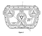
- Figure 3 illustrates another perspective view of a handheld GNSS device according to embodiments of the invention
- Figure 4 illustrates an exploded view of a handheld GNSS device including a viewfinder for a camera according to embodiments of the invention
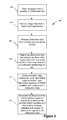
- Figure 5 illustrates a flowchart of a method for mitigating mutlipath error when determining the position of handheld GNSS device according to embodiments of the invention
- Figure 6 depicts an image generated from image data received according to a step of a method for mitigating mutlipath error when determining the position of handheld GNSS device according to embodiments of the invention
- Figure 7 depicts an image generated from obstruction data generated according to a step of a method for mitigating mutlipath error when determining the position of handheld GNSS device according to embodiments of the invention
- Figure 8 depicts locations of GNSS satellites in an image generated from obstruction data generated according to a step of a method for mitigating mutlipath error when determining the position of handheld GNSS device according to embodiments of the invention
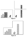
- Figure 9 depicts images generate from image data for three different orientations of a camera.
- Figure 10 depicts an image representing obstruction data generated from image data that was stitched together from image data for three orientations of a camera
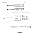
- Figure 11 illustrates a logic diagram showing the relationships between the various components of a handheld GNSS device according to embodiments of the invention.
- Figure 12 illustrates a typical computing system that may be employed to implement some or all of the processing functionality in certain embodiments.
- FIG 1 illustrates an exemplary handheld GNSS device 100.
- Handheld GNSS device 100 utilizes a single housing 102.
- Several GNSS elements are integral to the housing 102 in that they are within the housing or securely mounted thereto. A securely mounted element may be removable.
- Housing 102 allows the user to hold the handheld GNSS device 100 similar to the way one would hold a typical camera.
- the housing 102 may include GNSS antenna cover 104 to cover a GNSS antenna 402 (shown in exemplary exploded view in Figure 4 ) which may receive signals transmitted by a plurality of GNSS satellites and used by handheld GNSS device 100 to determine position.
- the GNSS antenna 402 is integral with the housing 102 in that it resides in the housing 102 under the GNSS antenna cover 104.
- GNSS antenna 402 may receive signals transmitted by at least four GNSS satellites.
- GNSS antenna cover 104 is located on the top side of handheld GNSS device 100.
- Handheld GNSS device 100 may further include at least one handgrip 108.
- two handgrips 108 are integral to the housing 102.
- the handgrips 108 may be covered with a rubber material for comfort and to reduce slippage of a user's hands.
- a front camera lens 110 is located on the front side of the handheld GNSS device 100.
- An image sensor (not shown) is mounted within handheld GNSS device 100 allowing the image sensor to work with front camera lens 110 to produced image data of scenes in front of handheld GNSS device 100.
- a second bottom camera lens 116 may be located on the bottom side of the handheld GNSS device 100 in the example shown in Figure 3 .
- the camera included may be a still or video camera.
- handheld GNSS device 100 may further include display 112 for displaying information to assist the user in positioning the device.
- Display 112 may be any electronic display such as a liquid crystal (LCD) display, light emitting diode (LED) display, and the like. Such display devices are well-known by those of ordinary skill in the art and any such device may be used.
- display 112 is integral with the back side of the housing 102 of handheld GNSS device 100.
- Handheld GNSS device 100 may further include a camera for recording still images or video. Such recording devices are well-known by those of ordinary skill in the art and any such device may be used.
- front camera lens 110 is located on the front side of handheld GNSS device 100.
- display 112 may be used to display the output of front camera lens 110.
- handheld GNSS device 100 may also include a second bottom camera lens 116 on the bottom of handheld GNSS device 100 for viewing and alignment of the handheld GNSS device 100 with a point of interest marker.
- the image of the point of interest marker may also be recorded along with the GNSS data to ensure that the GNSS receiver 808 was mounted correctly, or compensate for misalignment later based on the recorded camera information.
- a description of the bottom camera lens 116 and its use to compensate for misalignment may be found in US Patent Application No. 12/571,244, filed September 30, 2009 , assigned to the assignee of the present invention, and which is incorporated herein by reference in its entirety for all purposes.
- Handheld GNSS device 100 may further include orientation sensors (not shown) that may include various types of sensors such as horizon sensors, MEMS gyroscopes, or magnetic compasses for generating orientation data for the device.
- the orientation data describes the orientation of handheld GNS S device 100 and camera lens 110 with respect to a ground plane.
- Orientation data may be recorded by itself or associated with various other data such as GNSS position data or image data. As discussed below, the orientation data may be used to mitigate error due to multipath satellite signals.
- the horizon sensors may be any type of horizon sensor, such as an inclinometer, accelerometer, and the like. Such horizon sensors are well-known by those of ordinary skill in the art and any such device may be used. In one example, a representation of the output of the horizon sensors may be displayed using display 112.
- the horizon sensor information such as pitch and roll, can be recorded along with GNSS data. The horizon sensor information may be useful, for example, to later compensate for mis-leveling of the antenna.
- Magnetic compasses are well-know by those of ordinary skill in the art and any such device may be used. Magnetic compasses allow determination of the magnetic direction that handheld GNSS device 100 is facing. Magnetic compass data may be recorded with a captured image. Magnetic compass data may be useful, for example, the direction of image data obtained from the front facing camera.
- MEMS gyroscopes are well-know by those of ordinary skill in the art and any such device may be used.
- the MEMS gyroscopes allow measurement of the angular velocity of handheld GNSS device 100. Based on a starting direction from, for example, a magnetic compass, the MEMS gyroscope information may be used to determine the direction that the front of the device is facing.
- the MEMS gyroscope information may be recorded with a captured image.
- the MEMS gyroscope information may be used, for example, to determine the spatial relationship between two images captured by the front facing camera.
- Handheld GNSS device 100 may further include a distance sensor (not shown) to measure a linear distance.
- the distance sensor may use any range-finding technology, such as sonar, laser, radar, infrared, and the like. Such distance sensors are well-known by those of ordinary skill in the art and any such device may be used.
- Figure 3 illustrates a bottom view of the handheld GNSS device 100 according to embodiments of the invention.
- the handheld GNSS device 100 may be mounted on a tripod, or some other support structure, by a mounting structure such as three threaded bushes 114, in some embodiments of the invention.
- FIG. 5 illustrates an exemplary process 500 for mitigating the effects of multipath error using handheld GNSS device 100 according to embodiments of the invention.
- GNSS antenna 402 and GNSS receiver 408 receive signals from a plurality of GNSS satellites.
- a user will position handheld GNSS device 100 such that an image sensor, such as the sensor mounted for use with front camera lens 110, obtains image data of the area in front of handheld GNSS device 100.
- CPU 1108 ( Figure 11 ) receives orientation data from an orientation sensor of handheld GNSS device 100.
- CPU 1108 determines obstruction data that defines obstruction regions in the image data where structures obstruct the sky.
- CPU 1108 of handheld GNSS device 100 determines whether any structures represented in the obstruction data are obstructing handheld GNSS device 100's view of any satellites that are present in the field of view of the image data.
- CPU 1108 determines the location of the handheld GNSS device 100 based on signals from some of the plurality of GNSS satellites and the position of those satellites relative to the obstruction region as determined in step 510.
- Each step of exemplary process 500 is explained in further detail below.
- signals from a plurality of GNSS satellites are received by handheld GNSS device 100 through antenna 402 and GNSS receiver 408 of Figure 4 .
- the signals may comprise carrier harmonic signals that are modulated by pseudo-random binary codes that may be used to measure the delay relative to a local reference clock.
- Each satellite signal contains a unique satellite identification code that identifies the signal as coming from a particular satellite.
- measurements of the delay in receiving some of the signals relative to a reference clock may be used to determine the location of handheld GNSS device 100.
- an image sensor such as the sensor mounted with front camera lens 110, obtains image data that may be used to produce image 602 in Figure 6 .
- the image data includes data that represents mountain 604, building 606, and tree 608.
- the rest of the image data represents sky 610.
- the field of view of the image data produced by the image sensor mounted with front camera lens 110 may be obtained from the focusing and zoom settings of the lens. Alternatively, the field of view may be obtained from known fixed settings if the lens is a fixed focus and non-zoom lens.
- the image sensor using front camera lens 110 may have a fixed field of view of 45 degrees. However other fields of view may be used.
- orientation data is received from orientation sensors.
- the orientation data may provide enough information to determine the three dimensional orientation of handheld GNSS device 100 at the time when the image data in step 504 was obtained.
- the orientation data may include inclination data that describes the pitch and roll of the device with respect to the horizon and magnetic direction data that describes the magnetic direction that the device is pointing.
- the location in the physical world that the image data represents may be calculated.
- image data represents data taken when the image sensor was pointed due north and inclined at 15 degrees with respect to the horizon.
- the portion of the sky and landscape that the image data represents can be calculated.
- image data obtained from that position would have associated orientation data that indicated the image sensor was pointed northwest and inclined at 30 degrees with respect to the horizon.
- the portion of the sky and landscape that the image data represents may be calculated based on the orientation data and the field of view of the image data.
- the portions of the sky that the image data represents may be calculated, for example, by using the field of view information with orientation data for the image sensor.
- orientation data determines that the optical axis of the image sensor is at an azimuth of 30 degrees and an elevation above the horizon of 60 degrees.
- image sensor with a fixed field of view of 45 degrees that is symmetric about the optical axis.
- the image data from the image sensor would represent a region of the sky from an azimuth of 7.5 to 52.5 degrees and an elevation above the horizon from 37.5 to 82.5 degrees.
- image data from multiple orientations of the image sensor may be stitched together using known image processing techniques. Orientation data may also aid in the stitching process by defining the spatial relationship between the image data taken at two different orientations. Using the stitching process, image data can be obtained for the entire visible sky. Alternatively, instead of stitching the image data together, the image data at each unique orientation can be processed separately according to steps 508 and 510 below.
- image processing techniques are used to determine obstruction data that defines structures present in the image data that obstruct the view of the sky.
- Exemplary image processing techniques for carrying out step 508 may themselves include or employ color identification, spectrial analysis, infrared analysis, or edge detection.
- Image 702 of Figure 7 is generated from obstruction data based on the image data used to produce image 602 of Figure 6 .
- the obstruction data includes obstruction region 704 that accounts for the obstruction caused by mountain 604 and building 606 as well as obstruction region 706 that accounts for the obstruction caused by tree 608.
- the region in the obstruction data not covered by the obstruction regions is considered unobstructed sky 708.
- the position of GNSS satellites with respect to the obstruction regions is determined.
- the GNSS satellite data identify the location of GNSS satellites in the sky.
- the GNSS satellite data may include the elevation angles and azimuths of satellites in a GNSS constellation. This is information that is widely available to those of ordinary skill in the art.
- a representation of the exemplary results of step 506 is depicted in overlay 802 of Figure 8 . While such an overlay is not necessarily produced according to process 500, overlay 802 is useful for explaining step 506.
- Overlay 802 has the locations of satellites 804-812 marked with solid circles. Satellite 804 is obstructed by mountain 604, satellite 806 is obstructed by building 606, and satellite 812 is obstructed by obstruction 706 caused by tree 608. These satellites may be considered obstructed satellites. Satellites 808 and 810 are not obstructed. However, based on satellite 808's proximity to obstruction region 704, it may be considered a suspect satellite because delay measurements based on signals received from this satellite may be more prone to multipath error.
- the location of handheld GNSS device 100 is determined based on the signals from some of the plurality of GNSS satellites in step 502 and location of the plurality of GNSS satellites in the obstruction data as determined in step 510.
- the location of handheld GNSS device 100 may be determined based on the signals from satellites 808 and 810 with signals from other satellites not shown in Figure 8 while excluding signals from obstructed satellites 804, 806, and 812.
- satellite 808's proximity to obstruction region 704 may indicate that signals from satellite 808 are more likely to be affected by multipath error than satellite 810, which is further away from the obstruction regions.
- the signal from satellite 808 may be excluded or any delay measurement based on the signal can be de-weighted in the determination of the location of handheld GNSS device 100. De-weighting of a signal can be accomplished by devaluing the amount that measurements of that signal are used when determining the location of handheld GNSS device 100. This may be especially useful when there are signals from more than 4 satellites available, as that is the minimum number of satellites required to determine the location.
- Factors other than a satellite's proximity to an obstruction region may also be used to determine whether delay measurements based on signals from that satellite are prone to multipath error. For example, three dimensional effects may be considered. If a satellite with a direct line of sight to handheld GNSS device 100 is located 180 degrees from a large obstruction region, signals from the satellite may reflect off the structure represented by the obstruction region. Despite getting a direct signal from the satellite, handheld GNSS device 100 may also receive a reflected signal which may cause multipath error. In this example, based on the predicted source of reflected signals off the obstruction region, the satellite may be added to the suspect satellite list.
- whether a satellite is consider suspect may be determined based on whether the satellite has a probability of multipath error being above some multipath threshold.
- the probability of a satellite having multipath error above the threshold may be determined based on the positional factors discussed above (e.g., distance to obstruction regions or three dimensional affects), other factors, or a combination of factors.
- the threshold may be determined, for example, by computer simulations of handheld GNSS device 100 in a multipath environment.
- display 112 of handheld GNSS device 100 may provide an indication that the user should move the device to a different location to reduce multipath error.
- Figure 11 illustrates an exemplary logic diagram showing the relationships between the various components of handheld GNSS device 100.
- GNSS antenna 404 may send position data received from GNSS satellites to receiver 408.
- Receiver 408 may convert the received GNSS satellite signals into Earth-based coordinates, such as WGS84, ECEF, ENU, and the like.
- GNSS receiver 408 may further send the coordinates to CPU 1108 for processing along with other data.
- Orientation data 1112 may include pitch data from pitch horizon sensors and roll data from roll horizon sensors, for example.
- Image data 1110 from video or still camera may also be sent along to the CPU 1108 with the position data received by the GNSS antenna 402, positioning assistance data received by communication antenna 106, and orientation data 1112.
- CPU 1108 processes the data to determine the position of the point of interest marker and provides display data to be displayed on display 112.
- CPU 1108 may store or retrieve data from memory 1106. For example, image data and associated orientation data may be stored in memory 1106 until a determining whether any GNSS satellites are obstructed from view.
- GNSS satellite location data may also be stored in memory 1106.
- FIG. 12 illustrates an exemplary computing system 1200 that may be employed to implement processing functionality for various aspects of the current technology (e.g., as a GNSS device, receiver, CPU 1108, activity data logic/database, combinations thereof, and the like.). Components of computing system 1200 may be used to implement the steps of exemplary process 500. Those skilled in the relevant art will also recognize how to implement the current technology using other computer systems or architectures.
- Computing system 1200 may represent, for example, a user device such as a desktop, mobile phone, geodesic device, and so on as may be desirable or appropriate for a given application or environment.
- Computing system 1200 can include one or more processors, such as a processor 1204.
- Processor 1204 can be implemented using a general or special purpose processing engine such as, for example, a microprocessor, microcontroller or other control logic. In this example, processor 1204 is connected to a bus 1202 or other communication medium.
- the computing system 1200 may also include information storage mechanism 1210, which may include, for example, a media drive 1212 and a removable storage interface 1220.
- the media drive 1212 may include a drive or other mechanism to support fixed or removable storage media, such as a hard disk drive, a floppy disk drive, a magnetic tape drive, an optical disk drive, a CD or DVD drive (R or RW), or other removable or fixed media drive.
- Storage media 1218 may include, for example, a hard disk, floppy disk, magnetic tape, optical disk, CD or DVD, or other fixed or removable medium that is read by and written to by media drive 1212. As these examples illustrate, the storage media 1218 may include a computer-readable storage medium having stored therein particular computer software or data.
- information storage mechanism 1210 may include other similar instrumentalities for allowing computer programs or other instructions or data to be loaded into computing system 1200 .
- Such instrumentalities may include, for example, a removable storage unit 1222 and an interface 1220 , such as a program cartridge and cartridge interface, a removable memory (for example, a flash memory or other removable memory module) and memory slot, and other removable storage units 1222 and interfaces 1220 that allow software and data to be transferred from the removable storage unit 1222 to computing system 1200.
- Computing system 1200 can also include a communications interface 1224.
- Communications interface 1224 can be used to allow software and data to be transferred between computing system 1200 and external devices.
- Examples of communications interface 1224 can include a modem, a network interface (such as an Ethernet or other NIC card), a communications port (such as for example, a USB port), a PCMCIA slot and card, etc.
- Some examples of a channel include a phone line, a cellular phone link, an RF link, a network interface, a local or wide area network, and other communications channels.
- computer program product and “computer-readable storage medium” may be used generally to refer to media such as, for example, memory 1208, storage media 1218, or removable storage unit 1222 .
- These and other forms of computer-readable media may be involved in providing one or more sequences of one or more instructions to processor 1204 for execution.
- Such instructions generally referred to as "computer program code” (which may be grouped in the form of computer programs or other groupings), when executed, enable the computing system 1200 to perform features or functions of embodiments of the current technology.
- the software may be stored in a computer-readable medium and loaded into computing system 1200 using, for example, removable storage drive 1222, media drive 1212 or communications interface 1224.
- the control logic in this example, software instructions or computer program code
- the processor 1204 when executed by the processor 1204, causes the processor 1204 to perform the functions of the technology as described herein.
Applications Claiming Priority (1)
| Application Number | Priority Date | Filing Date | Title |
|---|---|---|---|
| US41720910P | 2010-11-24 | 2010-11-24 |
Publications (1)
| Publication Number | Publication Date |
|---|---|
| EP2458406A1 true EP2458406A1 (fr) | 2012-05-30 |
Family
ID=45350650
Family Applications (1)
| Application Number | Title | Priority Date | Filing Date |
|---|---|---|---|
| EP11189982A Ceased EP2458406A1 (fr) | 2010-11-24 | 2011-11-21 | Réduction de trajets multiples de signaux satellites dans des dispositifs GNSS |
Country Status (3)
| Country | Link |
|---|---|
| US (1) | US8717233B2 (fr) |
| EP (1) | EP2458406A1 (fr) |
| JP (1) | JP6297768B2 (fr) |
Cited By (3)
| Publication number | Priority date | Publication date | Assignee | Title |
|---|---|---|---|---|
| WO2014159294A3 (fr) * | 2013-03-14 | 2014-12-31 | Microsoft Corporation | Utilisation de données de visibilité satellitaire permettant d'obtenir une meilleure précision de localisation |
| WO2015194966A1 (fr) * | 2014-06-19 | 2015-12-23 | Kongsberg Seatex As | Procédé et système de contrôle de la qualité et de correction de données de position provenant de satellites de navigation dans des zones avec des objets d'obstruction |
| US20190164040A1 (en) * | 2017-11-30 | 2019-05-30 | Apple Inc. | Visual Inertial Odometry Health Fitting |
Families Citing this family (29)
| Publication number | Priority date | Publication date | Assignee | Title |
|---|---|---|---|---|
| DE102012224104A1 (de) * | 2012-12-20 | 2014-06-26 | Continental Teves Ag & Co. Ohg | Verfahren zum Bereitstellen eines GNSS-Signals |
| US9885789B2 (en) * | 2013-03-14 | 2018-02-06 | Google Llc | Accounting for atmospheric and terrestrial obstacles in geographic positioning |
| US20140266884A1 (en) * | 2013-03-15 | 2014-09-18 | Nextnav, Llc | Systems and methods for maintaining time synchronization |
| US9036682B2 (en) | 2013-05-03 | 2015-05-19 | Deere & Company | Phase multi-path mitigation |
| US9329274B2 (en) | 2013-07-09 | 2016-05-03 | Honeywell International Inc. | Code minus carrier multipath observation for satellite exclusion |
| US9720093B2 (en) | 2013-08-23 | 2017-08-01 | Javad Gnss, Inc. | Land surveying using GNSS device |
| US10386497B2 (en) | 2013-10-08 | 2019-08-20 | Javad Gnss, Inc. | Automated localization for GNSS device |
| US9671497B2 (en) | 2014-05-09 | 2017-06-06 | Javad Gnss, Inc. | Synchronization using multiple offset GNSS receiver channels |
| US10281588B2 (en) | 2014-07-17 | 2019-05-07 | Javad Gnss, Inc. | GNSS surveying using RTK engine verification |
| US10613231B2 (en) | 2014-12-18 | 2020-04-07 | Javad Gnss, Inc. | Portable GNSS survey system |
| US9804270B2 (en) | 2015-08-31 | 2017-10-31 | Qualcomm Incorporated | Sensor-based GNSS view zone selection |
| US10408944B2 (en) | 2016-01-29 | 2019-09-10 | Javad Gnss, Inc. | Hybrid RTK |
| US10514467B2 (en) | 2016-04-08 | 2019-12-24 | Javad Gnss, Inc. | Up sampling reference station data |
| WO2017205839A1 (fr) | 2016-05-27 | 2017-11-30 | Javad Gnss, Inc | Localisateur magnétique pour dispositif gnss |
| US10754045B2 (en) | 2016-08-09 | 2020-08-25 | Javad Gnss, Inc. | Clustering GNSS data |
| US11428822B2 (en) * | 2016-12-01 | 2022-08-30 | Google Llc | Methods and systems for location determination |
| US10495762B2 (en) * | 2017-05-19 | 2019-12-03 | Qualcomm Incorporated | Non-line-of-sight (NLoS) satellite detection at a vehicle using a camera |
| US10983220B2 (en) | 2017-11-20 | 2021-04-20 | Javad Gnss, Inc. | Spoofing detection and rejection |
| US11656076B2 (en) | 2018-05-15 | 2023-05-23 | Javad Gnss, Inc. | Method of calibrating a total station using a GNSS device |
| KR102314678B1 (ko) | 2019-02-25 | 2021-10-19 | 한국전자통신연구원 | 위성항법 다중경로오차 감쇄 방법 및 장치 |
| US11808866B2 (en) | 2019-08-16 | 2023-11-07 | Javad Gnss, Inc. | Total station with GNSS device |
| US11513234B2 (en) | 2019-09-13 | 2022-11-29 | Apple Inc. | Estimating device position in multipath environments |
| US11619745B2 (en) * | 2019-10-29 | 2023-04-04 | Qualcomm Incorporated | Camera-based GNSS environment detector |
| DE102019220051A1 (de) * | 2019-12-18 | 2021-06-24 | Robert Bosch Gmbh | Verfahren zur Bestimmung der Sichtbarkeit eines GNSS-Satelliten und Verfahren zur hochgenauen Positionsbestimmung sowie Computerprogramm, elektronisches Speichermedium und Vorrichtung |
| US11513237B2 (en) | 2020-07-17 | 2022-11-29 | Trimble Inc. | GNSS satellite line of sight detection |
| WO2022141535A1 (fr) * | 2020-12-31 | 2022-07-07 | 深圳市大疆创新科技有限公司 | Procédé de positionnement de plateforme mobile, plateforme mobile et support de stockage |
| US11809198B2 (en) * | 2021-05-10 | 2023-11-07 | Trimble Inc. | Hybrid sky and ground navigation for machine employing satellite positioning |
| CN113253306B (zh) * | 2021-06-07 | 2021-10-08 | 中国人民解放军国防科技大学 | 模拟gnss多径信道的方法及装置 |
| US20230059402A1 (en) * | 2021-08-19 | 2023-02-23 | Here Global B.V. | Method, apparatus, and system for providing increased accuracy for a positioning receiver in a multipath signal environment |
Citations (3)
| Publication number | Priority date | Publication date | Assignee | Title |
|---|---|---|---|---|
| US7033308B2 (en) | 2003-07-07 | 2006-04-25 | Fanuc Ltd | Automatic tool changing device for machine tool |
| US20100176992A1 (en) * | 2007-07-31 | 2010-07-15 | T Siobbel Stephen | Method and device for determining a position |
| EP2216657A1 (fr) * | 2009-02-04 | 2010-08-11 | Riegl Laser Measurement Systems GmbH | Procédé et installation de détermination de la position |
Family Cites Families (10)
| Publication number | Priority date | Publication date | Assignee | Title |
|---|---|---|---|---|
| JP2001289652A (ja) * | 2000-04-07 | 2001-10-19 | Honda Motor Co Ltd | ナビゲーション装置 |
| JP4004316B2 (ja) * | 2002-03-20 | 2007-11-07 | 株式会社トプコン | 測量装置及び測量装置を用いて画像データを取得する方法 |
| JP4391458B2 (ja) * | 2005-09-29 | 2009-12-24 | 三菱電機株式会社 | 測位装置、測位方法および測位プログラム |
| JP2007333636A (ja) * | 2006-06-16 | 2007-12-27 | Mitsubishi Electric Corp | 路側装置、端末装置およびdgps測位システム |
| JP2008096110A (ja) * | 2006-10-05 | 2008-04-24 | Alpine Electronics Inc | 測位装置、カーナビゲーション装置及び測位方法 |
| US8606498B2 (en) | 2007-02-16 | 2013-12-10 | Javad Gnss, Inc. | Path approximation for planar motion of a ground vehicle |
| PL2562578T3 (pl) * | 2007-03-16 | 2017-12-29 | Kollmorgen Corporation | System do panoramicznego przetwarzania obrazu |
| US8120527B2 (en) | 2008-01-30 | 2012-02-21 | Javad Gnss, Inc. | Satellite differential positioning receiver using multiple base-rover antennas |
| JP2009192448A (ja) * | 2008-02-18 | 2009-08-27 | Tama Art Univ | 情報表示装置及び情報提供システム |
| US9250328B2 (en) | 2009-09-30 | 2016-02-02 | Javad Gnss, Inc. | Graphics-aided remote position measurement with handheld geodesic device |
-
2011
- 2011-11-21 US US13/301,633 patent/US8717233B2/en active Active
- 2011-11-21 EP EP11189982A patent/EP2458406A1/fr not_active Ceased
- 2011-11-22 JP JP2011255021A patent/JP6297768B2/ja active Active
Patent Citations (3)
| Publication number | Priority date | Publication date | Assignee | Title |
|---|---|---|---|---|
| US7033308B2 (en) | 2003-07-07 | 2006-04-25 | Fanuc Ltd | Automatic tool changing device for machine tool |
| US20100176992A1 (en) * | 2007-07-31 | 2010-07-15 | T Siobbel Stephen | Method and device for determining a position |
| EP2216657A1 (fr) * | 2009-02-04 | 2010-08-11 | Riegl Laser Measurement Systems GmbH | Procédé et installation de détermination de la position |
Non-Patent Citations (1)
| Title |
|---|
| JUN-ICHI MEGURO ET AL: "GPS accuracy improvement by satellite selection using omnidirectional infrared camera", INTELLIGENT ROBOTS AND SYSTEMS, 2008. IROS 2008. IEEE/RSJ INTERNATIONAL CONFERENCE ON, IEEE, PISCATAWAY, NJ, USA, 22 September 2008 (2008-09-22), pages 1804 - 1810, XP031348241, ISBN: 978-1-4244-2057-5 * |
Cited By (6)
| Publication number | Priority date | Publication date | Assignee | Title |
|---|---|---|---|---|
| WO2014159294A3 (fr) * | 2013-03-14 | 2014-12-31 | Microsoft Corporation | Utilisation de données de visibilité satellitaire permettant d'obtenir une meilleure précision de localisation |
| CN105229490A (zh) * | 2013-03-14 | 2016-01-06 | 微软技术许可有限责任公司 | 使用卫星可见性数据来用于提升的位置准确性 |
| US9857474B2 (en) | 2013-03-14 | 2018-01-02 | Microsoft Technology Licensing, Llc | Using satellite visibility data for improved location accuracy |
| WO2015194966A1 (fr) * | 2014-06-19 | 2015-12-23 | Kongsberg Seatex As | Procédé et système de contrôle de la qualité et de correction de données de position provenant de satellites de navigation dans des zones avec des objets d'obstruction |
| US20190164040A1 (en) * | 2017-11-30 | 2019-05-30 | Apple Inc. | Visual Inertial Odometry Health Fitting |
| US11740321B2 (en) * | 2017-11-30 | 2023-08-29 | Apple Inc. | Visual inertial odometry health fitting |
Also Published As
| Publication number | Publication date |
|---|---|
| US8717233B2 (en) | 2014-05-06 |
| US20120293365A1 (en) | 2012-11-22 |
| JP6297768B2 (ja) | 2018-03-20 |
| JP2012112959A (ja) | 2012-06-14 |
Similar Documents
| Publication | Publication Date | Title |
|---|---|---|
| US8717233B2 (en) | Satellite signal multipath mitigation in GNSS devices | |
| US9228835B2 (en) | Visual stakeout | |
| EP2423703B1 (fr) | Dispositif de système de positionnement global portable | |
| EP2312330B1 (fr) | Mesure à distance aidée par graphiques avec un dispositif géodésique portable | |
| Noureldin et al. | Fundamentals of inertial navigation, satellite-based positioning and their integration | |
| EP2458405A1 (fr) | Mesure à distance aidée par graphiques avec un dispositif géodésique portable | |
| US10338228B2 (en) | Portable GNSS survey system | |
| US9478034B1 (en) | Geoposition determination by starlight refraction measurement | |
| US10976441B2 (en) | Method of using GNSS system having magnetic locator | |
| US20230251088A1 (en) | Method of calibrating a total station using a gnss device | |
| US10754045B2 (en) | Clustering GNSS data | |
| CN113295174B (zh) | 一种车道级定位的方法、相关装置、设备以及存储介质 | |
| US20240019587A1 (en) | Total station with gnss device | |
| US20230176233A1 (en) | Gnss positioning methods and devices using ppp-rtk, rtk, ssr, or like correction data | |
| RU2007149048A (ru) | Навигационное устройство с информацией, получаемой от камеры | |
| JP6783681B2 (ja) | 演算装置、演算方法およびプログラム | |
| Elsayed et al. | From Stationary to Mobile: Unleashing the Full Potential of Terrestrial LiDAR through Sensor Integration |
Legal Events
| Date | Code | Title | Description |
|---|---|---|---|
| PUAI | Public reference made under article 153(3) epc to a published international application that has entered the european phase |
Free format text: ORIGINAL CODE: 0009012 |
|
| AK | Designated contracting states |
Kind code of ref document: A1 Designated state(s): AL AT BE BG CH CY CZ DE DK EE ES FI FR GB GR HR HU IE IS IT LI LT LU LV MC MK MT NL NO PL PT RO RS SE SI SK SM TR |
|
| AX | Request for extension of the european patent |
Extension state: BA ME |
|
| 17P | Request for examination filed |
Effective date: 20121127 |
|
| 17Q | First examination report despatched |
Effective date: 20130103 |
|
| STAA | Information on the status of an ep patent application or granted ep patent |
Free format text: STATUS: THE APPLICATION HAS BEEN REFUSED |
|
| 18R | Application refused |
Effective date: 20131023 |