EP2458394B1 - Procédés et appareil pour tester des dispositifs d'alimentation électrique - Google Patents
Procédés et appareil pour tester des dispositifs d'alimentation électrique Download PDFInfo
- Publication number
- EP2458394B1 EP2458394B1 EP11190311.8A EP11190311A EP2458394B1 EP 2458394 B1 EP2458394 B1 EP 2458394B1 EP 11190311 A EP11190311 A EP 11190311A EP 2458394 B1 EP2458394 B1 EP 2458394B1
- Authority
- EP
- European Patent Office
- Prior art keywords
- electric power
- power
- testing apparatus
- coupling
- testing
- Prior art date
- Legal status (The legal status is an assumption and is not a legal conclusion. Google has not performed a legal analysis and makes no representation as to the accuracy of the status listed.)
- Active
Links
- 238000012360 testing method Methods 0.000 title claims description 184
- 238000000034 method Methods 0.000 title claims description 23
- 230000008878 coupling Effects 0.000 claims description 29
- 238000010168 coupling process Methods 0.000 claims description 29
- 238000005859 coupling reaction Methods 0.000 claims description 29
- 238000004088 simulation Methods 0.000 claims description 10
- 230000003134 recirculating effect Effects 0.000 claims description 9
- 230000001939 inductive effect Effects 0.000 claims description 8
- 230000009467 reduction Effects 0.000 description 14
- 238000001914 filtration Methods 0.000 description 10
- 230000005540 biological transmission Effects 0.000 description 9
- 230000000712 assembly Effects 0.000 description 6
- 238000000429 assembly Methods 0.000 description 6
- 238000009499 grossing Methods 0.000 description 5
- 238000002955 isolation Methods 0.000 description 5
- 238000013101 initial test Methods 0.000 description 4
- 230000008030 elimination Effects 0.000 description 3
- 238000003379 elimination reaction Methods 0.000 description 3
- 230000001172 regenerating effect Effects 0.000 description 3
- 230000001052 transient effect Effects 0.000 description 2
- 230000008859 change Effects 0.000 description 1
- 238000006243 chemical reaction Methods 0.000 description 1
- 230000000694 effects Effects 0.000 description 1
- 230000006870 function Effects 0.000 description 1
- 238000009434 installation Methods 0.000 description 1
- 238000004519 manufacturing process Methods 0.000 description 1
- 230000001105 regulatory effect Effects 0.000 description 1
- 230000002459 sustained effect Effects 0.000 description 1
- 230000001360 synchronised effect Effects 0.000 description 1
- 238000012956 testing procedure Methods 0.000 description 1
Images


Classifications
-
- G—PHYSICS
- G01—MEASURING; TESTING
- G01R—MEASURING ELECTRIC VARIABLES; MEASURING MAGNETIC VARIABLES
- G01R31/00—Arrangements for testing electric properties; Arrangements for locating electric faults; Arrangements for electrical testing characterised by what is being tested not provided for elsewhere
- G01R31/40—Testing power supplies
- G01R31/42—AC power supplies
Definitions
- the subject matter described herein relates generally to electric power device testing and, more particularly, to methods and apparatus for testing full-power converter assemblies.
- OETTMEIER M ET AL "Power-electronic-based machine emulator for high-power high-frequency drive converter test", VEHICLE POWER AND PROPULSION CONFERENCE (VPPC), 2010 IEEE, IEEE, 1 September 2010 (2010-09-01), pages 1-6 discloses a machine emulator for high-power high-frequency application configured to emulate a permanent-magnet synchronous machine for automotive application. The machine emulator mirrors the type and also the parameters of a machine by controlled power-electronic devices.
- At least some known full-power converter assemblies, or power converters are electrically tested up to their predetermined electrical ratings prior to shipping from a manufacturing facility to an installation site.
- One such test is typically referred to as a "full-power test”.
- Such full-power testing verifies performance of each power converter at their rated capacities. Smaller power converters, i.e., those power converters rated for 500 kilowatts (kW) or less are typically tested with testing apparatus that includes a full-power transformer, a full-power circuit breaker, and appropriately sized variable test loads that include motors with an adjustable brake and/or variable load resistor banks. However, for larger power converters in excess of 500 kW, the size and costs of the testing apparatus increases commensurately.
- the larger testing apparatus is expensive to purchase, install, and maintain, requires a large physical footprint, and may be unwieldy to position for testing power converters of varying sizes.
- At least some known power converter testing apparatus is typically electrically coupled to a local utility grid to supply the necessary testing power.
- a local utility grid to supply the necessary testing power.
- not all such utility grids are sufficiently powered to support large-scale power converter testing.
- utility grid connections in remote areas may not have the necessary voltage stability and may not have the necessary sustained current supply capabilities.
- bulk power purchasing from a utility on a transient basis may be expensive and may require coordination with the associated utility such that the utility can be prepared to support the large transient electrical loads that full-power converter testing will likely entail.
- many known power converter testing apparatus include a "point of common coupling" that transmits electric power into the testing apparatus and receives at least some of the output power from the testing apparatus.
- Some testing procedures typically include testing power converters at electrical frequencies that may not be consistent with local grid frequencies. For example, a power converter designed for a 50 Hertz (Hz) frequency, as is common in Europe, is difficult to test with a 60 Hz North American grid. Grid operating requirements typically restrict harmonic frequencies transmitted thereon. Therefore, grid isolation equipment that may include expensive filters may be required to support test activities of power converters.
- Approximating language may be applied to modify any quantitative representation that could permissibly vary without resulting in a change in the basic function to which it is related. Accordingly, a value modified by a term or terms, such as “about” and “substantially”, are not to be limited to the precise value specified. In at least some instances, the approximating language may correspond to the precision of an instrument for measuring the value.
- range limitations may be combined and/or interchanged, such ranges are identified and include all the sub-ranges contained therein unless context or language indicates otherwise.
- the exemplary systems and methods described herein overcome disadvantages of known power converter testing apparatus by providing a testing apparatus that simulates a utility grid electric power supply to the power converter being tested.
- the power converter testing apparatus includes a direct current (DC) link between an alternating current (AC) source and an AC test supply device that simulates a utility grid electric power supply to the apparatus being tested.
- DC direct current
- AC alternating current
- the power converter testing apparatus recirculates electric power in an internal loop rather than through a second utility grid connection, thereby eliminating the second utility grid connection.
- the power converter testing apparatus uses the single utility grid connection to merely transmit initial testing power and to replenish electric power that has dissipated in the electric power recirculation loop.
- using the single utility grid connection merely as an initial and make-up power source facilitates a reduction in the size of otherwise large electric power transmission devices, such as, electric power transformers and utility grid isolation circuit breakers.
- use of a single utility grid connection facilitates a reduction in the number of such electric power transformers and utility grid isolation circuit breakers.
- the power converter testing apparatus eliminates recirculating electric power back to the utility grid, the apparatus facilitates a reduction of induced electrical disturbances to the utility grid, such as, induced harmonics, thereby facilitating a reduction in the size and number of filtering equipment interfacing the utility grid and the testing apparatus.
- the apparatus is substantially isolated from the utility grid, testing the power converters using a range of frequencies, voltages, and power factors is facilitated.
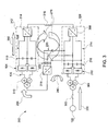
- FIG. 1 is a schematic view of a prior art full-power converter assembly testing apparatus 100.
- Testing apparatus 100 is configured to test a full-power converter assembly 102.
- Assembly 102 includes a rectifier portion 104 coupled to a high-frequency inverter portion 106 via a direct current (DC) link 108 that includes at least one capacitive device 110.
- DC link 108 includes a plurality of capacitive devices 110.
- Assembly 102 also includes a power transformer 112 coupled to inverter portion 106.
- inverter portion 106 is a three-level inverter, therefore assembly 102 is a three-level converter.
- inverter 106 is a two-level inverter or any multilevel inverter that enables operation of testing apparatus 100 as described herein.
- inverter and “converter” are used to describe any inverter and converter that enables operation of testing apparatus 100 as described herein.
- Prior art full-power converter assembly testing apparatus 100 includes a power transformer 120 coupled to an electric power grid 122 via a circuit breaker 124 (shown in an open position) coupled to rectifier portion 104 of full-power converter assembly 102 via a first test connection 126.
- power transformer 120 is a step-down transformer.
- both circuit breaker 124 and power transformer 120 are rated for the full-rated load of assembly 102.
- Testing apparatus 100 also includes a second test connection 128 coupled to transformer 112.
- Testing apparatus 100 further includes a high-frequency inductive coupling device (L hf ) 130 coupled to second test connection 128.
- Testing apparatus 100 also includes a variable frequency drive (VFD) 132 coupled to L hf 130.
- VFD 132 includes a DC link 138 that includes a plurality of capacitive devices 140.
- VFD 132 also includes a power transformer 142 coupled to L hf 130.
- Power transformer 142 is typically a step-down transformer.
- Testing apparatus 100 further includes an active front end (AFE) 150 coupled to VFD 132 via a DC link 152 that includes a plurality of capacitive devices 154. Testing apparatus 100 also includes a power transformer 156 coupled to AFE 150. Power transformer 156 is typically a step-up transformer. Testing apparatus 100 further includes a circuit breaker 158 (shown in an open position) coupling grid 122 to power transformer 156. Also, typically, both circuit breaker 158 and power transformer 156 are rated for the full-rated load of assembly 102. Testing apparatus 100 also includes an inductive-capacitive filtering device 160 coupled to grid 122, circuit breaker 124, and circuit breaker 158. Testing apparatus 100 further includes a point of common coupling (POCC) 170 that is defined by a coupling of an input section 172 of testing apparatus 100 and an output section 174 of testing apparatus 100.
- POCC point of common coupling
- circuit breakers 124 and 158 are in a closed position (both are shown in an open position in FIG. 1 ) and electric power grid 122 is coupled to input section 172 and output section 174 of testing apparatus 100.
- Alternating current (AC) (not shown) is transmitted from grid 122 at a predetermined grid AC voltage, and a substantially consistent frequency, to power transformer 120 as shown by current directional arrow 180.
- Power transformer 120 receives the AC current at the grid AC voltage, steps-down the AC voltage and steps-up the AC electric current, and transmits AC electric current at a predetermined value and a predetermined AC voltage via first test connection 126 to rectifier portion 104 of full-power converter assembly 102 being tested.
- Rectifier portion 104 receives the AC current at the AC voltage and rectifies such electric power to a predetermined DC current having a predetermined DC voltage.
- the DC current is transmitted through DC link 108 to high-frequency inverter portion 106, wherein capacitive devices 110 facilitate smoothing of the associated DC voltage.
- Inverter portion 106 converts the received DC current at the DC voltage to an AC current at a predetermined AC voltage and a predetermined AC frequency with a predetermined real-to-reactive power ratio.
- the converted AC power is transmitted from inverter portion 106 to power transformer 112, wherein transformer 112 steps-up the voltage and steps-down the current to predetermined values.
- electric power transmitted from full-power converter assembly 102 is at least occasionally at approximately rated, or near rated, full power conditions.
- assembly 102 While tested by testing apparatus 100, assembly 102 is typically operated to vary an output voltage within a range that may extend from 0 to 6 kilovolts (kV) and an output frequency within a range that may extend from 0 to 600 Hertz (Hz). Some assemblies 102 may be tested specifically at grid-rated frequency, typically 50 Hz or 60 Hz, depending on the shipping destination of assembly 102.
- kV kilovolts
- Hz Hertz
- AC electric power is transmitted from full-power converter assembly 102 to VFD 132 via second test connection 128 and L hf 130, wherein L hf 130 facilitates filtering high frequency harmonic distortions from the AC electric power transmitted to power transformer 142.
- Power transformer 142 receives the transmitted, filtered AC current at the transmitted and filtered AC voltage, steps-down the filtered AC voltage and steps-up the filtered AC electric current, and transmits AC electric current to a predetermined value and a predetermined AC voltage to high-frequency inverter portion 136.
- Inverter portion 136 receives the AC current at the AC voltage transmitted from power transformer 142 and converts the AC power to a predetermined DC current having a predetermined DC voltage while simulating a predetermined loading on assembly 102.
- the converted DC power is transmitted to AFE 150 via DC links 138 and 152, wherein capacitive devices 140 and 154 facilitate smoothing the transmitted DC power.
- AFE 150 receives the DC power transmitted from high-frequency inverter portion 136 and converts the received DC current at the DC voltage to an AC current at a predetermined AC voltage and a predetermined AC frequency with a predetermined real-to-reactive power ratio.
- electric power transmitted from AFE 150 has a frequency at or near electric power grid 122 frequency.
- the AC power is transmitted from AFE 150 to power transformer 156, wherein transformer 156 steps-up the AC voltage and steps-down the AC current for transmission to POCC 170 via circuit breaker 158 and output section 174.
- Such AC power is approximately at rated grid voltage.
- Inductive-capacitive filtering device 160 facilitates filtering harmonic distortions from the AC power transmitted to POCC 170 to reduce a potential for harmonic distortions being transmitted to electric power grid 122, and for meeting grid total harmonic distortion (THD) standards imposed by local regulatory authorities and/or the owner/operator of grid 122. However, while being at least effective in meeting such standards, such filtering may not remove all harmonic distortions.
- TDD grid total harmonic distortion
- prior art full-power converter assembly testing apparatus 100 recirculates electric power therethrough as shown by power recirculation arrows 190. While the majority of electric power is recirculated within testing apparatus 100, at least a portion of electric power is transmitted back into electric power grid 122, with at least some harmonic distortions therein, and at least a portion of electric power dissipated within testing apparatus 100 is restored via electric power grid 122. Furthermore, in operation, voltages, currents, and frequencies are controlled via at least some manual and at least some automated modulation of assembly 102, VFD 132, and AFE 150 using associated control devices (none shown). Upon completion of testing, assembly 102, VFD 132, and AFE 150 are modulated to reduce the amount of electric power recirculating within until circuit breakers 124 and 158 are opened and remaining power within testing apparatus 100 is dissipated into heat energy.
- FIG. 2 is a schematic view of an exemplary full-power converter assembly testing apparatus 200 that may be used instead of testing apparatus 100 (shown in FIG. 1 ).
- testing apparatus 200 includes a grid circuit breaker 202 (shown in the open position) coupled to electric power grid 122. Circuit breaker 202 has rated power transmission parameters less than those of circuit breaker 124 (described further below).
- Testing apparatus 200 also includes a voltage modulation device 204 coupled to circuit breaker 202.
- voltage modulation device 204 is a variac unit.
- Such variac unit includes a variable ratio transformer that includes a substantially continuous, high-resolution tap changing device that further includes at least one remotely-controlled drive device operably coupled thereto (neither shown).
- Testing apparatus 200 further includes a power transformer 206 coupled to optional voltage modulation device 204 that is similar to power transformer 120, however, transformer 206 has rated power transmission parameters less than those of power transformer 120 (also described further below).
- Testing apparatus 200 also includes a variable frequency test drive (VFTD) 208 that is similar to VFD 132 (shown in FIG. 1 ) and coupled to power transformer 206.
- VFTD 208 includes a rectifier portion 210 coupled to a high-frequency inverter portion 212 via a DC link 214 that includes a plurality of capacitive devices 216.
- power transformer 206 is coupled to rectifier portion 210.
- Testing apparatus 200 also includes an AFE 218 coupled to DC link 214 of VFTD 208 via a DC link 220 and a plurality of capacitive devices 222.
- AFE 218 is substantially similar to AFE 150 (shown in FIG. 1 ).
- Testing apparatus 200 further includes an optional low pass filter (LPF) unit 224 coupled to AFE 218.
- Testing apparatus 200 also includes power transformer 120, first test connection 126, second test connection 128, L hf 130, and power transformer 142.
- full-power converter assembly 102 is coupled to first test connection and second test connection 128.
- Testing apparatus 200 does not include a POCC 170 coupling an input section 172 with an output section 174 (all shown in FIG. 1 ).
- apparatus 200 includes a single connection with electric power grid 122 via grid circuit breaker 202. Therefore, power converter testing apparatus 200 recirculates electric power in an internal loop rather than through a second utility grid connection, thereby eliminating the second utility grid connection, i.e., output section 174 and POCC 170.
- Power converter testing apparatus 200 uses the single utility grid connection at circuit breaker 202 to merely transmit initial testing power and to replenish electric power that has dissipated in the electric power recirculation loop.
- circuit breaker 202 may have rated power transmission parameters less than those of circuit breaker 124 (shown in FIG. 1 ) and power transformer 206 may have rated power transmission parameters less than those of power transformer 120.
- testing apparatus 200 facilitates a reduction of induced electrical disturbances to grid 122, such as, induced harmonics, thereby facilitating a reduction in the size and number of filtering equipment interfacing grid 122 and testing apparatus 200, i.e., inductive-capacitive filtering device 160 (shown in FIG. 1 ).
- filtering equipment interfacing grid 122 and testing apparatus 200 i.e., inductive-capacitive filtering device 160 (shown in FIG. 1 ).
- Such elimination of unnecessary equipment, reductions in size of remaining equipment, and elimination of power transfer from testing apparatus 200 into grid 122 facilitate a reduction in dissipated and otherwise wasted energy, thereby facilitating an increase in efficiency of testing apparatus 200 over that of testing apparatus 100.
- grid circuit breaker 202 is in a closed position (shown in an open position in FIG. 2 ) and electric power grid 122 is coupled to voltage modulation device 204 of testing apparatus 200.
- Alternating current (AC) (not shown) is transmitted from grid 122 at a predetermined grid AC voltage, and a substantially consistent frequency, to power transformer 206 via voltage modulation device 204 as shown by a power directional arrow 230.
- Voltage modulation device 204 is locally or remotely operated to adjust a tap changer about the variable ratio transformer therein to finely adjust an incoming AC voltage and AC current that is transmitted to power transformer 206.
- Power transformer 206 receives the AC current at the adjusted AC voltage, steps-down the AC voltage and steps-up the AC current, and transmits AC current at a predetermined value and a predetermined AC voltage to rectifier portion 210 of VFTD 208.
- Rectifier portion 210 receives the AC current at the AC voltage and rectifies such electric power to a predetermined DC current having a predetermined DC voltage.
- the DC current as shown by a power directional arrow 240, is transmitted through DC link 220 to AFE 218, wherein capacitive devices 222 facilitate smoothing the transmitted DC power.
- AFE 218 receives the DC power transmitted from rectifier portion 210 and converts the received DC current at the DC voltage to an AC current at a predetermined AC voltage and a predetermined AC frequency with a predetermined real-to-reactive power ratio.
- electric power transmitted from AFE 218 has a frequency range such that the frequency may be varied to simulate input frequencies from a plurality of devices that include, without limitation, wind turbine generators (not shown).
- the AC power is transmitted from AFE 218 to LPF unit 224, as shown by power directional arrow 250, wherein LPF unit 224 filters (or, chops) higher-frequency harmonics from the transmitted AC power.
- LPF unit 224 is not used because AFE 218 is configured to transmit AC power therefrom with little to no higher-frequency harmonics therein.
- the AC power having the filtered AC voltages and currents is transmitted from LPF unit 224 to power transformer 120.
- Power transformer 120 receives the AC current at the filtered AC voltage, steps-down the AC voltage and steps-up the AC electric current, and transmits AC electric current at a predetermined value and a predetermined AC voltage via first test connection 126 to rectifier portion 104 of full-power converter assembly 102 being tested.
- Rectifier portion 104 receives the AC current at the AC voltage and rectifies such electric power to a predetermined DC current having a predetermined DC voltage.
- the DC current is transmitted through DC link 108 to high-frequency inverter portion 106, as shown by a power directional arrow 260, wherein capacitive devices 110 facilitate smoothing of the associated DC voltage.
- Inverter portion 106 converts the received DC current at the DC voltage to an AC current at a predetermined AC voltage and a predetermined AC frequency with a predetermined real-to-reactive power ratio.
- the converted AC power is transmitted from inverter portion 106 to power transformer 112, wherein transformer 112 steps-up the voltage and steps-down the current to predetermined values.
- assembly 102 is typically operated to vary an output voltage within a range that may extend from 0 to 6 kV and an output frequency within a range that may extend from 0 to 600 Hz.
- Some assemblies 102 may be tested specifically at grid-rated frequency, typically 50 Hz or 60 Hz, depending on the shipping destination of assembly 102.
- AC electric power is transmitted from full-power converter assembly 102 to VFTD 208 via second test connection 128 and L hf 130, wherein L hf 130 facilitates filtering high frequency harmonic distortions from the AC electric power transmitted to power transformer 142.
- Power transformer 142 receives the transmitted, filtered AC current at the transmitted, filtered AC voltage, steps-down the filtered AC voltage and steps-up the filtered AC electric current, and transmits AC electric current to a predetermined value and a predetermined AC voltage to high-frequency inverter portion 212.
- Inverter portion 212 receives the AC current at the AC voltage transmitted from power transformer 142 and converts the AC power to a predetermined DC current having a predetermined DC voltage while simulating a predetermined loading on assembly 102.
- the converted DC power is transmitted via recirculation to AFE 218 via DC links 214 and 220, wherein capacitive devices 216 and 222 facilitate smoothing the transmitted DC power.
- loading may include, without limitation, actual loading of the full-power conversion assembly being tested with a driven electo-mechanical apparatus and/or an emulated electro-mechanical loading via a variable frequency drive device, both as described herein.
- full-power converter assembly testing apparatus 200 recirculates electric power therethrough as shown by power recirculation arrows 270.
- electric power is pulled in from electric power grid 122.
- Substantially all of the electric power is recirculated within testing apparatus 200, while at least a portion of the electric power is dissipated as heat energy.
- Substantially none of the recirculating electric power is transmitted back into electric power grid 122, however, makeup electric power is transmitted into testing apparatus 200 from grid 122 with at least a portion of electric power dissipated within testing apparatus 200 restored via electric power grid 122.
- voltages, currents, and frequencies are controlled via at least some manual and at least some automated modulation of assembly 102, VFTD 208, AFE 218, and voltage modulation device 204 using associated control devices (none shown).
- assembly 102, VFTD 208, AFE 218, and voltage modulation device 204 are modulated to reduce the amount of electric power recirculating within and to substantially reduce electric power transmitted into testing apparatus 200 from electric power grid 122 until circuit breaker 202 is opened and remaining recirculating power is dissipated into heat energy.
- testing apparatus 200 simulates a utility grid electric power supply to the power converter being tested, i.e., apparatus 102.
- power converter testing apparatus 200 includes DC link 220 between AC source, i.e., inverter portion 212 and AC test supply device, i.e., AFE 218 that simulates electric power grid 122. Therefore, power converter testing apparatus 200 recirculates electric power in an internal loop rather than through a second utility grid connection, thereby eliminating the second utility grid connection, i.e., output section 174 and POCC 170.
- Power converter testing apparatus 200 uses the single utility grid connection at circuit breaker 202 to merely transmit initial testing power into testing apparatus 200 and to replenish electric power that has dissipated therein.
- apparatus 200 facilitates a reduction of induced electrical disturbances to grid 122, such as, induced harmonics.
- FIG. 3 is a schematic view of an alternative full-power converter assembly testing apparatus 300.
- Testing apparatus 300 is similar to testing apparatus 200 (shown in FIG. 2 ) with the exception that testing apparatus 300 is more suitable for low-frequency testing as compared to testing apparatus 200 that is more suitable for high-frequency testing.
- testing apparatus 300 is more suitable for testing the associated assemblies within a voltage range of 0 to 3 kV and a frequency range of 0 to 100 Hz
- testing apparatus 200 is more suitable for testing the associated assemblies within a voltage range of 0 to 6 kV and a frequency range of 0 to 600 Hz.
- testing apparatus 300 includes a grid circuit breaker 302 (shown in the open position) coupled to electric power grid 122. Testing apparatus 300 also includes a power transformer 304 coupled to grid circuit breaker 302. Testing apparatus 300 further includes a variable frequency test drive (VFTD) 306 coupled to power transformer 304. VFTD 306 is similar to VFTD 208 (shown in FIG. 2 ) with the exception that VFTD 306 includes a low-frequency inverter portion 308 in contrast to high-frequency inverter portion 212 (shown in FIG. 2 ).
- rectifier portion 210, DC link 214, and capacitive devices 216 are substantially similar to those related devices associated with testing apparatus 200.
- Testing apparatus 300 also includes AFE 218 coupled to DC link 214 of VFTD 306 via DC link 220 and plurality of capacitive devices 222. Testing apparatus further includes a power transformer 310 coupled to AFE 218. Power transformer 310, AFE 218, DC link 220, and capacitive devices 222 are substantially similar to the related devices associated with testing apparatus 200.
- a full-power converter assembly 312 is positioned within testing apparatus 300 and coupled therein via first test connection 126 and second test connection 128.
- assembly 312 is similar to assembly 102 (shown in FIG. 2 ) with the exception that assembly 312 includes a low-frequency inverter portion 314 in contrast to high-frequency inverter portion 106 (shown in FIG. 2 ).
- rectifier portion 104, DC link 108, and capacitive devices 110 are substantially similar to devices associated with testing apparatus 200.
- Assembly 312 is coupled to VFTD 306 via a low-frequency inductive coupling device L lf 316.
- Testing apparatus 300 differs from testing apparatus 200 by eliminating optional LPF unit 224, voltage modulation device 204, power transformer 112, and power transformer 142. Operation of testing apparatus 300 is similar to operation of testing apparatus 200. Alternatively, some embodiments of testing apparatus 300 may include an optional LPF unit similar to LPF unit 224 (shown in FIG. 2 ). Also, alternatively, some embodiments of testing apparatus 300 may include a voltage modulation device similar to voltage modulation device 204 (shown in FIG. 2 ).
- FIG. 4 is a schematic view of another alternative full-power converter assembly testing apparatus 400.
- Apparatus 400 is substantially similar to testing apparatus 300 (shown in FIG. 3 ) with the exception that apparatus 400 includes a low-frequency inductive coupling device L lf 402 and a low-frequency inverter portion 404 that defme a virtual machine 406. Virtual machine 406 is controlled and modulated to simulate a load on full-power converter assembly 312.
- some embodiments of testing apparatus 400 may include an optional LPF unit similar to LPF unit 224 (shown in FIG. 2 ).
- some embodiments of testing apparatus 400 may include a voltage modulation device similar to voltage modulation device 204 (shown in FIG. 2 ).
- FIG. 5 is a schematic view of yet another alternative full-power converter assembly testing apparatus 500.
- Apparatus 500 is substantially similar to apparatus 400 (shown in FIG. 4 ) with the exception that apparatus 500 does not include low-frequency inductive coupling device L lf 402 and low-frequency inverter portion 404 to define virtual machine 406 (all shown in FIG. 4 ). Rather, apparatus 500 includes a machine 502 that, in this alternative exemplary embodiment, is a motor-generator.
- Machine 502 includes a motor 504 rotatably coupled to a generator 506 via a shaft 508.
- Machine 502 is controlled and modulated to establish loads on full-power converter assembly 312.
- testing apparatus 500 may include an optional LPF unit similar to LPF unit 224 (shown in FIG. 2 ). Also, alternatively, some embodiments of testing apparatus 500 may include a voltage modulation device similar to voltage modulation device 204 (shown in FIG. 2 ).
- full-power converter assembly testing apparatus 200, 300, 400, and 500 are modified to test regenerative full-power converters (not shown).
- Such regenerative full-power converters include an active front end similar to AFE 218 (shown in FIGs. 2 , 3 , 4 , and 5 ) in place of rectifier 104 (shown in FIGs. 2 , 3 , 4 , and 5 ).
- Power flows 250. 260, and 270 (all shown in FIGs. 2 , 3 , 4 , and 5 ) may then be transmitted in both directions.
- Such a regenerative full-power converter may be used to test braking operation of industrial drive trains and converters used for renewable energy sources, for example, wind turbines.
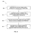
- FIG. 6 is a flow chart illustrating an exemplary method 600 that may be used in assembling full-power converter assembly testing apparatus 200 (shown in FIG. 2 ).
- an electric power supply apparatus i.e., circuit breaker 202, voltage modulation device 204, and power transformer 206 (all shown in FIG. 2 ) is coupled 602 to electric power grid 122.
- a DC generation apparatus i.e., rectifier portion 210 (shown in FIG. 2 ) is coupled 604 to an electric power supply apparatus, i.e., power transformer 206.
- An electric power grid simulation device, i.e., AFE 218 (shown in FIG. 2 ) is coupled 606 to rectifier portion 210.
- Full-power converter assembly test connection 126 (shown in FIG. 2 ) is coupled 608 to AFE 218.
- Fig. 7 is a flow chart illustrating an exemplary method 700 that may be used in testing full-power converter assembly 102 (shown in FIG. 2 ) using testing apparatus 200 (shown in FIG. 2 ).
- full-power converter assembly 102 is coupled 702 to electric power supply test connection 126 and 128 (both shown in FIG. 2 ).
- Full-power converter assembly 102 is coupled 704 to a test load, i.e., VFTD 208 (shown in FIG. 2 ).
- Electric power supply test connection 126 is coupled 706 to DC link 220 (shown in FIG. 2 ). Electric power is recirculated 708 from VFTD 208 to full-power converter assembly 102.
- the above-described power converter testing apparatus provides a cost effective and reliable method for increasing efficiency and performance of power converter testing apparatus during testing operations.
- the power converter testing apparatus facilitates increasing the operating efficiency of the testing operations by facilitating use of a direct current (DC) link between an alternating current (AC) source and an AC test supply device that simulates a utility grid electric power supply to the apparatus being tested.
- DC direct current
- AC alternating current
- the power converter testing apparatus recirculates electric power in an internal loop rather than through a second utility grid connection, thereby eliminating the second utility grid connection.
- the power converter testing apparatus uses the single utility grid connection to merely transmit initial testing power and to replenish electric power that has dissipated in the electric power recirculation loop.
- using the single utility grid connection merely as an initial and make-up power source facilitates a reduction in the size of otherwise large electric power transmission devices, such as, electric power transformers and utility grid isolation circuit breakers.
- use of a single utility grid connection facilitates a reduction in the number of such electric power transformers and utility grid isolation circuit breakers.
- the power converter testing apparatus eliminates recirculating electric power back to the utility grid, the apparatus facilitates a reduction of induced electrical disturbances to the utility grid, such as, induced harmonics, thereby facilitating a reduction in the size and number of filtering equipment interfacing the utility grid and the testing apparatus.
- the apparatus is substantially isolated from the utility grid, testing the power converters using a range of frequencies, voltages, and power factors is facilitated.
- Exemplary embodiments of systems and methods for testing a full-power converter assembly are described above in detail.
- the system and methods are not limited to the specific embodiments described herein, but rather, components of systems and/or steps of the method may be utilized independently and separately from other components and/or steps described herein.
- the systems and methods may also be used in combination with other electrical systems and methods, and are not limited to practice with only the power converter testing apparatus as described herein. Rather, the exemplary embodiment can be implemented and utilized in connection with many other electrical system and testing applications.
Landscapes
- Engineering & Computer Science (AREA)
- Power Engineering (AREA)
- Physics & Mathematics (AREA)
- General Physics & Mathematics (AREA)
- Testing Electric Properties And Detecting Electric Faults (AREA)
- Testing Relating To Insulation (AREA)
- Power Conversion In General (AREA)
- Tests Of Circuit Breakers, Generators, And Electric Motors (AREA)
- Control Of Electric Motors In General (AREA)
- Supply And Distribution Of Alternating Current (AREA)
Claims (13)
- Un appareil de test (200/300/400/500) pour un test à pleine puissance d'un ensemble convertisseur (102) comprenant :un appareil d'alimentation de puissance électrique d'un réseau (202/204) ;un redresseur (210) couplé audit appareil d'alimentation de puissance électrique d'un réseau ;un dispositif de simulation du réseau de puissance électrique (218/224) couplé audit redresseur (210)un dispositif d'entraînement à fréquence variable (208) couplé au redresseur pour fournir une simulation d'une charge de machine ; etune connexion test (126/128) de l'ensemble convertisseur couplée audit dispositif de simulation du réseau de puissance électrique.
- Un appareil de test (200/300/400/500) selon la revendication 1, dans lequel ledit appareil d'alimentation de puissance électrique d'un réseau (202/204) comprend un transformateur à rapport variable (204).
- Un appareil de test (200/300/400/500) selon la revendication 1 ou la revendication 2, dans lequel une liaison DC (214) est couplée au redresseur (210).
- Un appareil de test (200/300/400/500) selon une quelconque revendication précédente, dans lequel ledit dispositif de simulation de puissance du réseau électrique (218/224) comprend un dispositif de contrôle de fréquence d'extrémité avant actif (218).
- Un appareil de test (200/300/400/500) selon une quelconque revendication précédente, dans lequel ledit dispositif de simulation de puissance du réseau électrique (218/224) comprend un filtre passe-bas (224).
- Un appareil de test (200/300/400/500) selon une quelconque revendication précédente, comprenant en outre au moins un de :un dispositif de couplage à haute fréquence inductif (130) ;un dispositif de couplage à basse fréquence inductif (316/402) ; etune unité de moteur-générateur (502).
- Une méthode d'assemblage d'un appareillage de test pour le test à pleine puissance d'un ensemble convertisseur, ladite méthode comprenant :le couplage d'un appareil d'alimentation de puissance électrique (202/204) à un réseau électrique (122) ;le couplage d'un redresseur (210) à l'appareil d'alimentation de puissance électrique ;le couplage d'un dispositif de simulation du réseau de puissance électrique (218) au redresseur (210) ;le couplage d'un dispositif d'entraînement à fréquence variable (132) qui simule substantiellement une charge de machine au dispositif de simulation du réseau de puissance électrique au redresseur (210) : etle couplage d'une connexion test de l'ensemble convertisseur au dispositif de simulation du réseau de puissance électrique.
- Une méthode selon la revendication 7, dans laquelle le couplage d'un appareil d'alimentation de puissance électrique (204) à un réseau de puissance électrique comprend le couplage d'un transformateur à rapport variable au réseau de puissance électrique.
- Une méthode selon la revendication 7 ou la revendication 8, dans laquelle le couplage du redresseur (210) à l'appareil d'alimentation de puissance électrique comprend le couplage d'une liaison DC et du redresseur à l'appareil d'alimentation de puissance électrique.
- Une méthode selon une quelconque des revendications 7 à 9, dans laquelle le couplage d'un dispositif de simulation de puissance du réseau électrique (218) au redresseur (210) comprend le couplage d'un dispositif de contrôle de fréquence (132, 208) au redresseur (210).
- Une méthode selon une quelconque des revendications 7 à 10, dans laquelle le couplage d'un dispositif de simulation du réseau de puissance électrique au redresseur (210) comprend le couplage d'un filtre passe-bas (224) au dispositif de contrôle de fréquence (208).
- Une méthode en accord avec une quelconque des revendications 7 à 11, comprenant en outre le couplage du dispositif d'entraînement à fréquence variable (132) à au moins un de :un dispositif de couplage inductif à haute fréquence (130) ;un dispositif de couplage inductif à basse fréquence (316) ; etune unité de moteur-générateur.
- Une méthode pour tester un ensemble convertisseur à pleine puissance, ladite méthode comprenant :le couplage d'un ensemble convertisseur (102) à une connexion test d'alimentation de puissance électrique (126, 128) ;le couplage d'un ensemble convertisseur (102) à une charge test (208) ;l'assemblage de l'appareil de test selon une quelconque des revendications 7 à 12; etla recirculation de la puissance électrique de la charge test vers l'ensemble convertisseur.
Applications Claiming Priority (1)
| Application Number | Priority Date | Filing Date | Title |
|---|---|---|---|
| US12/956,785 US8604822B2 (en) | 2010-11-30 | 2010-11-30 | Methods and apparatus for testing electric power devices |
Publications (3)
| Publication Number | Publication Date |
|---|---|
| EP2458394A2 EP2458394A2 (fr) | 2012-05-30 |
| EP2458394A3 EP2458394A3 (fr) | 2013-11-13 |
| EP2458394B1 true EP2458394B1 (fr) | 2014-10-08 |
Family
ID=45094493
Family Applications (1)
| Application Number | Title | Priority Date | Filing Date |
|---|---|---|---|
| EP11190311.8A Active EP2458394B1 (fr) | 2010-11-30 | 2011-11-23 | Procédés et appareil pour tester des dispositifs d'alimentation électrique |
Country Status (5)
| Country | Link |
|---|---|
| US (1) | US8604822B2 (fr) |
| EP (1) | EP2458394B1 (fr) |
| JP (1) | JP5898474B2 (fr) |
| CN (1) | CN102539957B (fr) |
| RU (1) | RU2583233C2 (fr) |
Cited By (1)
| Publication number | Priority date | Publication date | Assignee | Title |
|---|---|---|---|---|
| DE102017115513B3 (de) | 2017-07-11 | 2018-05-30 | Woodward Kempen Gmbh | Vorrichtung und Verfahren zum Überprüfen des elektro-dynamischen Verhaltens eines Antriebsstrangs einer Stromerzeugungseinrichtung am Netz |
Families Citing this family (15)
| Publication number | Priority date | Publication date | Assignee | Title |
|---|---|---|---|---|
| US9939795B2 (en) | 2013-01-24 | 2018-04-10 | Trane International Inc. | Dynamic simulated motor for controller testing |
| CN104052305B (zh) | 2013-03-14 | 2019-01-25 | 通用电气公司 | 功率变换系统 |
| CN104052079A (zh) * | 2013-03-15 | 2014-09-17 | 余名俊 | 电能回馈型电子负载 |
| US9664716B1 (en) | 2013-03-15 | 2017-05-30 | Meg-Alert, Inc. | Automatic insulation resistance testers |
| FR3015672B1 (fr) | 2013-12-23 | 2016-02-05 | Ge Energy Products France Snc | Systeme et procede de test d'une machine tournante |
| US9632011B2 (en) | 2013-12-23 | 2017-04-25 | General Electric Company | System and method for testing a gas turbine |
| EP2930837A1 (fr) * | 2014-04-10 | 2015-10-14 | GE Energy Power Conversion Technology Ltd | Transformateurs électriques |
| EP2961021A1 (fr) * | 2014-06-27 | 2015-12-30 | Siemens Aktiengesellschaft | Système de distribution d'énergie sous-marine et son procédé |
| US10811882B2 (en) | 2016-05-26 | 2020-10-20 | Ge Energy Power Conversion Technology Ltd | Solar inverter grid emulation mode |
| CN105974247B (zh) * | 2016-07-21 | 2018-08-28 | 北京金风科创风电设备有限公司 | 导电滑环的测试系统及方法 |
| US10056840B1 (en) | 2017-12-06 | 2018-08-21 | Hamilton Sundstrand Corporation | Feed-referenced regenerative DC load |
| US11448710B2 (en) | 2019-03-15 | 2022-09-20 | Hamilton Sundstrand Corporation | Regenerative load bank systems and methods |
| US11378628B2 (en) * | 2019-09-02 | 2022-07-05 | Toshiba Mitsubishi—Electric Industrial Systems Corporation | Testing device of inverter device |
| CN114503419A (zh) * | 2020-02-07 | 2022-05-13 | 东芝三菱电机产业系统株式会社 | 分布式电源用电力转换系统 |
| ES2969669A1 (es) * | 2022-10-17 | 2024-05-21 | Cinergia Power Solutions S L | Sistema para prueba de productos electricos en circuito cerrado |
Family Cites Families (14)
| Publication number | Priority date | Publication date | Assignee | Title |
|---|---|---|---|---|
| JPH04264271A (ja) * | 1991-02-20 | 1992-09-21 | Toshiba Corp | 電力変換装置の試験方法 |
| JP3613972B2 (ja) * | 1998-04-16 | 2005-01-26 | 神鋼電機株式会社 | インバータ試験装置 |
| JP2008167655A (ja) * | 2001-08-27 | 2008-07-17 | Shinko Electric Co Ltd | インバータ試験装置 |
| US20030090257A1 (en) * | 2001-10-30 | 2003-05-15 | Howes Lawrence H. | Method and apparatus for load testing electrical systems |
| US6775160B2 (en) | 2002-09-27 | 2004-08-10 | The Aerospace Corporation | Dynamic DC source and load energy recycling power system |
| US20050286274A1 (en) * | 2004-06-29 | 2005-12-29 | Hans-Erik Pfitzer | Self-testing power supply apparatus, methods and computer program products |
| US7405553B1 (en) | 2005-10-31 | 2008-07-29 | At&T Corp. | Load testing of uninterrupted power supply systems using regenerative loading by supplying percentage of a test power |
| MX2008016209A (es) * | 2006-07-03 | 2009-02-17 | Vestas Wind Sys As | Sistema para probar turbinas eolicas. |
| US20080186741A1 (en) | 2007-02-02 | 2008-08-07 | Mark Rabo | Method and system adapted to regenerate load energy in ac-to-dc and dc-to-ac power converter systems |
| US7486099B1 (en) | 2008-02-28 | 2009-02-03 | Caterpillar Inc. | System and method for testing power transistors |
| JP5223659B2 (ja) * | 2008-05-13 | 2013-06-26 | 富士電機株式会社 | 電力変換装置の試験装置 |
| US8427331B2 (en) | 2008-12-31 | 2013-04-23 | Caterpillar Inc. | System and method for testing power transistors |
| DE102009018377A1 (de) * | 2009-04-23 | 2010-10-28 | Converteam Gmbh | Verfahren und elektrische Schaltung zum Testen eines an ein elektrisches Energieversorgungsnetz anschließbaren Energieerzeugers oder Energieverbrauchers |
| RU88812U1 (ru) * | 2009-05-12 | 2009-11-20 | Обособленное подразделение НАУЧНО-ИССЛЕДОВАТЕЛЬСКИЙ ИНСТИТУТ АВТОМАТИКИ И ЭЛЕКТРОМЕХАНИКИ ТОМСКОГО ГОСУДАРСТВЕННОГО УНИВЕРСИТЕТА СИСТЕМ УПРАВЛЕНИЯ И РАДИОЭЛЕКТРОНИКИ (НИИ АЭМ ТУСУР) | Комплекс имитации нагрузки для испытаний систем электропитания космических аппаратов |
-
2010
- 2010-11-30 US US12/956,785 patent/US8604822B2/en active Active
-
2011
- 2011-11-23 EP EP11190311.8A patent/EP2458394B1/fr active Active
- 2011-11-28 JP JP2011258625A patent/JP5898474B2/ja active Active
- 2011-11-29 RU RU2011149186/28A patent/RU2583233C2/ru active
- 2011-11-30 CN CN201110403047.9A patent/CN102539957B/zh active Active
Cited By (2)
| Publication number | Priority date | Publication date | Assignee | Title |
|---|---|---|---|---|
| DE102017115513B3 (de) | 2017-07-11 | 2018-05-30 | Woodward Kempen Gmbh | Vorrichtung und Verfahren zum Überprüfen des elektro-dynamischen Verhaltens eines Antriebsstrangs einer Stromerzeugungseinrichtung am Netz |
| WO2019011846A1 (fr) | 2017-07-11 | 2019-01-17 | Woodward Kempen Gmbh | Dispositif et procédé de contrôle du comportement électrodynamique d'une chaîne cinématique d'un dispositif de génération d'énergie sur le réseau |
Also Published As
| Publication number | Publication date |
|---|---|
| US8604822B2 (en) | 2013-12-10 |
| CN102539957B (zh) | 2016-01-20 |
| EP2458394A2 (fr) | 2012-05-30 |
| US20120133389A1 (en) | 2012-05-31 |
| RU2583233C2 (ru) | 2016-05-10 |
| CN102539957A (zh) | 2012-07-04 |
| EP2458394A3 (fr) | 2013-11-13 |
| JP2012118070A (ja) | 2012-06-21 |
| RU2011149186A (ru) | 2013-06-10 |
| JP5898474B2 (ja) | 2016-04-06 |
Similar Documents
| Publication | Publication Date | Title |
|---|---|---|
| EP2458394B1 (fr) | Procédés et appareil pour tester des dispositifs d'alimentation électrique | |
| Mohamed et al. | Modeling and assessment analysis of various compensation topologies in bidirectional IWPT system for EV applications | |
| CN102545759B (zh) | 为双馈感应发电机提供增加的涡轮机输出的方法和系统 | |
| CN107112765A (zh) | 船舶上的配电 | |
| Stieneker et al. | Medium-voltage DC research grid Aachen | |
| CN107196537B (zh) | 模拟同步发电机特性和谐波电压发生的装置及控制方法 | |
| CN104485821A (zh) | 配电用直流变压器装置 | |
| CN104953582A (zh) | 一种三相电网扰动发生装置及其控制方法 | |
| CN103616584B (zh) | 一种变频器测试平台及变频器测试平台的调试方法 | |
| CN100468908C (zh) | 旋转电磁型统一潮流控制装置 | |
| Ugalde-Loo et al. | Open access simulation toolbox for the grid connection of offshore wind farms using multi-terminal HVDC networks | |
| Hawke et al. | A new utility-scale power converter for large fuel cell power plants with individual stack power control | |
| Rodrigues et al. | Active power filter operation of an electric vehicle applied to single-phase networks | |
| Tabrez et al. | Analysis of a three-phase to seven-phase transformer under unbalanced input | |
| Vijayan et al. | High‐performance bi‐directional z‐source inverter for locomotive drive application | |
| Hasanzadeh et al. | Comprehensive study of power quality criteria generated by PV converters and their impacts on distribution transformers | |
| Ogoulola et al. | Performance evaluation of interphase transformers based on a new 48-pulse AC–DC converter for industrial applications | |
| Mu et al. | A novel locomotive auxiliary converter control strategy with harmonic suppression for avoiding resonance voltage accidents in an electrified railway | |
| CN205610331U (zh) | 一种便携式逆变电源抢修车 | |
| Gunji et al. | Fundamental Research on Control Method for Power Conversion Circuit of Wireless In‐Wheel Motor Using Magnetic Resonance Coupling | |
| KR102355107B1 (ko) | 복수의 주파수를 사용하여 전력의 흐름을 제어하는 전력 제어 시스템 및 방법 | |
| CN113708409B (zh) | 基于模块化固态变压器的海上风电电力变换方法及系统 | |
| Budu et al. | OPERATIONS AND CONTROL OF SMART TRANSFORMER FOR MANAGERIAL PERFORMANCE OF STAND-ALONE OPERATIONS | |
| Wu et al. | A DC Charging Pile for New Energy Electric Vehicles | |
| Singer et al. | Aircraft Electrical Power Systems and Nonlinear Dynamic Loads |
Legal Events
| Date | Code | Title | Description |
|---|---|---|---|
| PUAI | Public reference made under article 153(3) epc to a published international application that has entered the european phase |
Free format text: ORIGINAL CODE: 0009012 |
|
| AK | Designated contracting states |
Kind code of ref document: A2 Designated state(s): AL AT BE BG CH CY CZ DE DK EE ES FI FR GB GR HR HU IE IS IT LI LT LU LV MC MK MT NL NO PL PT RO RS SE SI SK SM TR |
|
| AX | Request for extension of the european patent |
Extension state: BA ME |
|
| PUAL | Search report despatched |
Free format text: ORIGINAL CODE: 0009013 |
|
| AK | Designated contracting states |
Kind code of ref document: A3 Designated state(s): AL AT BE BG CH CY CZ DE DK EE ES FI FR GB GR HR HU IE IS IT LI LT LU LV MC MK MT NL NO PL PT RO RS SE SI SK SM TR |
|
| AX | Request for extension of the european patent |
Extension state: BA ME |
|
| RIC1 | Information provided on ipc code assigned before grant |
Ipc: G01R 31/40 20060101AFI20131010BHEP Ipc: G01R 31/42 20060101ALI20131010BHEP |
|
| 17P | Request for examination filed |
Effective date: 20140513 |
|
| RBV | Designated contracting states (corrected) |
Designated state(s): AL AT BE BG CH CY CZ DE DK EE ES FI FR GB GR HR HU IE IS IT LI LT LU LV MC MK MT NL NO PL PT RO RS SE SI SK SM TR |
|
| GRAP | Despatch of communication of intention to grant a patent |
Free format text: ORIGINAL CODE: EPIDOSNIGR1 |
|
| RIC1 | Information provided on ipc code assigned before grant |
Ipc: G01R 31/42 20060101ALI20140611BHEP Ipc: G01R 31/40 20140101AFI20140611BHEP |
|
| INTG | Intention to grant announced |
Effective date: 20140714 |
|
| GRAS | Grant fee paid |
Free format text: ORIGINAL CODE: EPIDOSNIGR3 |
|
| GRAA | (expected) grant |
Free format text: ORIGINAL CODE: 0009210 |
|
| AK | Designated contracting states |
Kind code of ref document: B1 Designated state(s): AL AT BE BG CH CY CZ DE DK EE ES FI FR GB GR HR HU IE IS IT LI LT LU LV MC MK MT NL NO PL PT RO RS SE SI SK SM TR |
|
| REG | Reference to a national code |
Ref country code: GB Ref legal event code: FG4D |
|
| REG | Reference to a national code |
Ref country code: CH Ref legal event code: EP Ref country code: AT Ref legal event code: REF Ref document number: 690912 Country of ref document: AT Kind code of ref document: T Effective date: 20141015 |
|
| REG | Reference to a national code |
Ref country code: IE Ref legal event code: FG4D |
|
| REG | Reference to a national code |
Ref country code: DE Ref legal event code: R096 Ref document number: 602011010395 Country of ref document: DE Effective date: 20141120 |
|
| REG | Reference to a national code |
Ref country code: NL Ref legal event code: T3 |
|
| REG | Reference to a national code |
Ref country code: NO Ref legal event code: T2 Effective date: 20141008 |
|
| REG | Reference to a national code |
Ref country code: AT Ref legal event code: MK05 Ref document number: 690912 Country of ref document: AT Kind code of ref document: T Effective date: 20141008 |
|
| REG | Reference to a national code |
Ref country code: LT Ref legal event code: MG4D |
|
| PG25 | Lapsed in a contracting state [announced via postgrant information from national office to epo] |
Ref country code: LT Free format text: LAPSE BECAUSE OF FAILURE TO SUBMIT A TRANSLATION OF THE DESCRIPTION OR TO PAY THE FEE WITHIN THE PRESCRIBED TIME-LIMIT Effective date: 20141008 Ref country code: PT Free format text: LAPSE BECAUSE OF FAILURE TO SUBMIT A TRANSLATION OF THE DESCRIPTION OR TO PAY THE FEE WITHIN THE PRESCRIBED TIME-LIMIT Effective date: 20150209 Ref country code: FI Free format text: LAPSE BECAUSE OF FAILURE TO SUBMIT A TRANSLATION OF THE DESCRIPTION OR TO PAY THE FEE WITHIN THE PRESCRIBED TIME-LIMIT Effective date: 20141008 Ref country code: IS Free format text: LAPSE BECAUSE OF FAILURE TO SUBMIT A TRANSLATION OF THE DESCRIPTION OR TO PAY THE FEE WITHIN THE PRESCRIBED TIME-LIMIT Effective date: 20150208 Ref country code: ES Free format text: LAPSE BECAUSE OF FAILURE TO SUBMIT A TRANSLATION OF THE DESCRIPTION OR TO PAY THE FEE WITHIN THE PRESCRIBED TIME-LIMIT Effective date: 20141008 |
|
| PG25 | Lapsed in a contracting state [announced via postgrant information from national office to epo] |
Ref country code: LV Free format text: LAPSE BECAUSE OF FAILURE TO SUBMIT A TRANSLATION OF THE DESCRIPTION OR TO PAY THE FEE WITHIN THE PRESCRIBED TIME-LIMIT Effective date: 20141008 Ref country code: HR Free format text: LAPSE BECAUSE OF FAILURE TO SUBMIT A TRANSLATION OF THE DESCRIPTION OR TO PAY THE FEE WITHIN THE PRESCRIBED TIME-LIMIT Effective date: 20141008 Ref country code: PL Free format text: LAPSE BECAUSE OF FAILURE TO SUBMIT A TRANSLATION OF THE DESCRIPTION OR TO PAY THE FEE WITHIN THE PRESCRIBED TIME-LIMIT Effective date: 20141008 Ref country code: CY Free format text: LAPSE BECAUSE OF FAILURE TO SUBMIT A TRANSLATION OF THE DESCRIPTION OR TO PAY THE FEE WITHIN THE PRESCRIBED TIME-LIMIT Effective date: 20141008 Ref country code: RS Free format text: LAPSE BECAUSE OF FAILURE TO SUBMIT A TRANSLATION OF THE DESCRIPTION OR TO PAY THE FEE WITHIN THE PRESCRIBED TIME-LIMIT Effective date: 20141008 Ref country code: SE Free format text: LAPSE BECAUSE OF FAILURE TO SUBMIT A TRANSLATION OF THE DESCRIPTION OR TO PAY THE FEE WITHIN THE PRESCRIBED TIME-LIMIT Effective date: 20141008 Ref country code: AT Free format text: LAPSE BECAUSE OF FAILURE TO SUBMIT A TRANSLATION OF THE DESCRIPTION OR TO PAY THE FEE WITHIN THE PRESCRIBED TIME-LIMIT Effective date: 20141008 Ref country code: GR Free format text: LAPSE BECAUSE OF FAILURE TO SUBMIT A TRANSLATION OF THE DESCRIPTION OR TO PAY THE FEE WITHIN THE PRESCRIBED TIME-LIMIT Effective date: 20150109 |
|
| PG25 | Lapsed in a contracting state [announced via postgrant information from national office to epo] |
Ref country code: BE Free format text: LAPSE BECAUSE OF NON-PAYMENT OF DUE FEES Effective date: 20141130 |
|
| REG | Reference to a national code |
Ref country code: DE Ref legal event code: R097 Ref document number: 602011010395 Country of ref document: DE |
|
| PG25 | Lapsed in a contracting state [announced via postgrant information from national office to epo] |
Ref country code: CZ Free format text: LAPSE BECAUSE OF FAILURE TO SUBMIT A TRANSLATION OF THE DESCRIPTION OR TO PAY THE FEE WITHIN THE PRESCRIBED TIME-LIMIT Effective date: 20141008 Ref country code: DK Free format text: LAPSE BECAUSE OF FAILURE TO SUBMIT A TRANSLATION OF THE DESCRIPTION OR TO PAY THE FEE WITHIN THE PRESCRIBED TIME-LIMIT Effective date: 20141008 Ref country code: SK Free format text: LAPSE BECAUSE OF FAILURE TO SUBMIT A TRANSLATION OF THE DESCRIPTION OR TO PAY THE FEE WITHIN THE PRESCRIBED TIME-LIMIT Effective date: 20141008 Ref country code: EE Free format text: LAPSE BECAUSE OF FAILURE TO SUBMIT A TRANSLATION OF THE DESCRIPTION OR TO PAY THE FEE WITHIN THE PRESCRIBED TIME-LIMIT Effective date: 20141008 Ref country code: RO Free format text: LAPSE BECAUSE OF FAILURE TO SUBMIT A TRANSLATION OF THE DESCRIPTION OR TO PAY THE FEE WITHIN THE PRESCRIBED TIME-LIMIT Effective date: 20141008 Ref country code: MC Free format text: LAPSE BECAUSE OF FAILURE TO SUBMIT A TRANSLATION OF THE DESCRIPTION OR TO PAY THE FEE WITHIN THE PRESCRIBED TIME-LIMIT Effective date: 20141008 |
|
| PLBE | No opposition filed within time limit |
Free format text: ORIGINAL CODE: 0009261 |
|
| STAA | Information on the status of an ep patent application or granted ep patent |
Free format text: STATUS: NO OPPOSITION FILED WITHIN TIME LIMIT |
|
| REG | Reference to a national code |
Ref country code: IE Ref legal event code: MM4A |
|
| 26N | No opposition filed |
Effective date: 20150709 |
|
| PG25 | Lapsed in a contracting state [announced via postgrant information from national office to epo] |
Ref country code: IE Free format text: LAPSE BECAUSE OF NON-PAYMENT OF DUE FEES Effective date: 20141123 |
|
| REG | Reference to a national code |
Ref country code: FR Ref legal event code: PLFP Year of fee payment: 5 |
|
| PG25 | Lapsed in a contracting state [announced via postgrant information from national office to epo] |
Ref country code: SI Free format text: LAPSE BECAUSE OF FAILURE TO SUBMIT A TRANSLATION OF THE DESCRIPTION OR TO PAY THE FEE WITHIN THE PRESCRIBED TIME-LIMIT Effective date: 20141008 |
|
| PG25 | Lapsed in a contracting state [announced via postgrant information from national office to epo] |
Ref country code: SM Free format text: LAPSE BECAUSE OF FAILURE TO SUBMIT A TRANSLATION OF THE DESCRIPTION OR TO PAY THE FEE WITHIN THE PRESCRIBED TIME-LIMIT Effective date: 20141008 |
|
| PG25 | Lapsed in a contracting state [announced via postgrant information from national office to epo] |
Ref country code: BG Free format text: LAPSE BECAUSE OF FAILURE TO SUBMIT A TRANSLATION OF THE DESCRIPTION OR TO PAY THE FEE WITHIN THE PRESCRIBED TIME-LIMIT Effective date: 20141008 |
|
| PG25 | Lapsed in a contracting state [announced via postgrant information from national office to epo] |
Ref country code: LU Free format text: LAPSE BECAUSE OF NON-PAYMENT OF DUE FEES Effective date: 20141123 Ref country code: HU Free format text: LAPSE BECAUSE OF FAILURE TO SUBMIT A TRANSLATION OF THE DESCRIPTION OR TO PAY THE FEE WITHIN THE PRESCRIBED TIME-LIMIT; INVALID AB INITIO Effective date: 20111123 Ref country code: TR Free format text: LAPSE BECAUSE OF FAILURE TO SUBMIT A TRANSLATION OF THE DESCRIPTION OR TO PAY THE FEE WITHIN THE PRESCRIBED TIME-LIMIT Effective date: 20141008 Ref country code: MT Free format text: LAPSE BECAUSE OF FAILURE TO SUBMIT A TRANSLATION OF THE DESCRIPTION OR TO PAY THE FEE WITHIN THE PRESCRIBED TIME-LIMIT Effective date: 20141008 |
|
| REG | Reference to a national code |
Ref country code: FR Ref legal event code: PLFP Year of fee payment: 6 |
|
| REG | Reference to a national code |
Ref country code: FR Ref legal event code: PLFP Year of fee payment: 7 |
|
| PG25 | Lapsed in a contracting state [announced via postgrant information from national office to epo] |
Ref country code: MK Free format text: LAPSE BECAUSE OF FAILURE TO SUBMIT A TRANSLATION OF THE DESCRIPTION OR TO PAY THE FEE WITHIN THE PRESCRIBED TIME-LIMIT Effective date: 20141008 |
|
| REG | Reference to a national code |
Ref country code: FR Ref legal event code: PLFP Year of fee payment: 8 |
|
| PG25 | Lapsed in a contracting state [announced via postgrant information from national office to epo] |
Ref country code: AL Free format text: LAPSE BECAUSE OF FAILURE TO SUBMIT A TRANSLATION OF THE DESCRIPTION OR TO PAY THE FEE WITHIN THE PRESCRIBED TIME-LIMIT Effective date: 20141008 |
|
| PGFP | Annual fee paid to national office [announced via postgrant information from national office to epo] |
Ref country code: NL Payment date: 20231020 Year of fee payment: 13 |
|
| PGFP | Annual fee paid to national office [announced via postgrant information from national office to epo] |
Ref country code: GB Payment date: 20231019 Year of fee payment: 13 |
|
| PGFP | Annual fee paid to national office [announced via postgrant information from national office to epo] |
Ref country code: NO Payment date: 20231023 Year of fee payment: 13 Ref country code: IT Payment date: 20231019 Year of fee payment: 13 Ref country code: FR Payment date: 20231020 Year of fee payment: 13 Ref country code: DE Payment date: 20231019 Year of fee payment: 13 Ref country code: CH Payment date: 20231201 Year of fee payment: 13 |