EP2458362A2 - Dispositif de capteur de pression - Google Patents
Dispositif de capteur de pression Download PDFInfo
- Publication number
- EP2458362A2 EP2458362A2 EP20120156088 EP12156088A EP2458362A2 EP 2458362 A2 EP2458362 A2 EP 2458362A2 EP 20120156088 EP20120156088 EP 20120156088 EP 12156088 A EP12156088 A EP 12156088A EP 2458362 A2 EP2458362 A2 EP 2458362A2
- Authority
- EP
- European Patent Office
- Prior art keywords
- passage
- compressible element
- cavity
- fluid
- pressure
- Prior art date
- Legal status (The legal status is an assumption and is not a legal conclusion. Google has not performed a legal analysis and makes no representation as to the accuracy of the status listed.)
- Granted
Links
- 239000012530 fluid Substances 0.000 claims abstract description 73
- 239000012528 membrane Substances 0.000 claims abstract description 27
- 238000001514 detection method Methods 0.000 claims abstract description 13
- 238000000465 moulding Methods 0.000 claims description 12
- 230000008878 coupling Effects 0.000 claims description 9
- 238000010168 coupling process Methods 0.000 claims description 9
- 238000005859 coupling reaction Methods 0.000 claims description 9
- 238000004026 adhesive bonding Methods 0.000 claims description 3
- 238000003466 welding Methods 0.000 claims description 2
- 238000004891 communication Methods 0.000 abstract description 3
- 239000000463 material Substances 0.000 description 22
- 238000007710 freezing Methods 0.000 description 19
- 230000008014 freezing Effects 0.000 description 19
- 230000006870 function Effects 0.000 description 10
- 230000002093 peripheral effect Effects 0.000 description 9
- MWUXSHHQAYIFBG-UHFFFAOYSA-N Nitric oxide Chemical compound O=[N] MWUXSHHQAYIFBG-UHFFFAOYSA-N 0.000 description 6
- 238000005452 bending Methods 0.000 description 5
- 238000007789 sealing Methods 0.000 description 5
- 239000000243 solution Substances 0.000 description 5
- 239000007788 liquid Substances 0.000 description 4
- 229920001296 polysiloxane Polymers 0.000 description 4
- 239000012815 thermoplastic material Substances 0.000 description 4
- 230000006835 compression Effects 0.000 description 3
- 238000007906 compression Methods 0.000 description 3
- 238000009434 installation Methods 0.000 description 3
- 230000000630 rising effect Effects 0.000 description 3
- 229920002943 EPDM rubber Polymers 0.000 description 2
- 230000008901 benefit Effects 0.000 description 2
- 230000000694 effects Effects 0.000 description 2
- 238000002347 injection Methods 0.000 description 2
- 239000007924 injection Substances 0.000 description 2
- 238000005259 measurement Methods 0.000 description 2
- 239000007769 metal material Substances 0.000 description 2
- 238000000034 method Methods 0.000 description 2
- 235000019391 nitrogen oxide Nutrition 0.000 description 2
- 230000000284 resting effect Effects 0.000 description 2
- 239000010409 thin film Substances 0.000 description 2
- XLYOFNOQVPJJNP-UHFFFAOYSA-N water Substances O XLYOFNOQVPJJNP-UHFFFAOYSA-N 0.000 description 2
- XSQUKJJJFZCRTK-UHFFFAOYSA-N Urea Chemical compound NC(N)=O XSQUKJJJFZCRTK-UHFFFAOYSA-N 0.000 description 1
- PNEYBMLMFCGWSK-UHFFFAOYSA-N aluminium oxide Inorganic materials [O-2].[O-2].[O-2].[Al+3].[Al+3] PNEYBMLMFCGWSK-UHFFFAOYSA-N 0.000 description 1
- 229940095054 ammoniac Drugs 0.000 description 1
- 239000007864 aqueous solution Substances 0.000 description 1
- 230000004888 barrier function Effects 0.000 description 1
- 239000004202 carbamide Substances 0.000 description 1
- 239000000919 ceramic Substances 0.000 description 1
- 239000003153 chemical reaction reagent Substances 0.000 description 1
- 238000002485 combustion reaction Methods 0.000 description 1
- 150000001875 compounds Chemical class 0.000 description 1
- 238000001816 cooling Methods 0.000 description 1
- 238000006073 displacement reaction Methods 0.000 description 1
- 239000013013 elastic material Substances 0.000 description 1
- 238000000605 extraction Methods 0.000 description 1
- 230000008571 general function Effects 0.000 description 1
- 238000003780 insertion Methods 0.000 description 1
- 230000037431 insertion Effects 0.000 description 1
- 239000002184 metal Substances 0.000 description 1
- 229960003753 nitric oxide Drugs 0.000 description 1
- 239000004033 plastic Substances 0.000 description 1
- 230000010287 polarization Effects 0.000 description 1
- 230000009467 reduction Effects 0.000 description 1
- 239000011265 semifinished product Substances 0.000 description 1
- 230000035945 sensitivity Effects 0.000 description 1
- 238000000926 separation method Methods 0.000 description 1
- 229910052710 silicon Inorganic materials 0.000 description 1
- 239000010703 silicon Substances 0.000 description 1
- 239000007787 solid Substances 0.000 description 1
- 238000007711 solidification Methods 0.000 description 1
- 230000008023 solidification Effects 0.000 description 1
- 230000002269 spontaneous effect Effects 0.000 description 1
- 230000003068 static effect Effects 0.000 description 1
- 238000012360 testing method Methods 0.000 description 1
- 229920001169 thermoplastic Polymers 0.000 description 1
- 238000011144 upstream manufacturing Methods 0.000 description 1
Images


Classifications
-
- G—PHYSICS
- G01—MEASURING; TESTING
- G01L—MEASURING FORCE, STRESS, TORQUE, WORK, MECHANICAL POWER, MECHANICAL EFFICIENCY, OR FLUID PRESSURE
- G01L9/00—Measuring steady of quasi-steady pressure of fluid or fluent solid material by electric or magnetic pressure-sensitive elements; Transmitting or indicating the displacement of mechanical pressure-sensitive elements, used to measure the steady or quasi-steady pressure of a fluid or fluent solid material, by electric or magnetic means
- G01L9/0041—Transmitting or indicating the displacement of flexible diaphragms
- G01L9/0051—Transmitting or indicating the displacement of flexible diaphragms using variations in ohmic resistance
- G01L9/0052—Transmitting or indicating the displacement of flexible diaphragms using variations in ohmic resistance of piezoresistive elements
-
- G—PHYSICS
- G01—MEASURING; TESTING
- G01L—MEASURING FORCE, STRESS, TORQUE, WORK, MECHANICAL POWER, MECHANICAL EFFICIENCY, OR FLUID PRESSURE
- G01L19/00—Details of, or accessories for, apparatus for measuring steady or quasi-steady pressure of a fluent medium insofar as such details or accessories are not special to particular types of pressure gauges
- G01L19/06—Means for preventing overload or deleterious influence of the measured medium on the measuring device or vice versa
- G01L19/0672—Leakage or rupture protection or detection
-
- G—PHYSICS
- G01—MEASURING; TESTING
- G01L—MEASURING FORCE, STRESS, TORQUE, WORK, MECHANICAL POWER, MECHANICAL EFFICIENCY, OR FLUID PRESSURE
- G01L19/00—Details of, or accessories for, apparatus for measuring steady or quasi-steady pressure of a fluent medium insofar as such details or accessories are not special to particular types of pressure gauges
- G01L19/14—Housings
- G01L19/142—Multiple part housings
- G01L19/143—Two part housings
-
- G—PHYSICS
- G01—MEASURING; TESTING
- G01L—MEASURING FORCE, STRESS, TORQUE, WORK, MECHANICAL POWER, MECHANICAL EFFICIENCY, OR FLUID PRESSURE
- G01L19/00—Details of, or accessories for, apparatus for measuring steady or quasi-steady pressure of a fluent medium insofar as such details or accessories are not special to particular types of pressure gauges
- G01L19/14—Housings
- G01L19/147—Details about the mounting of the sensor to support or covering means
Definitions
- the present invention relates to a pressure-sensor device having the feature indicated in the preamble of claim 1.
- the fluid being measured is delivered, via the aforesaid duct, to the cavity of the body of the sensitive component in such a way as to cause bending of the membrane portion.
- the amount of said bending which is a function of the pressure of the fluid, is measured via the detection element, the output signal of which is representative of the pressure value.
- the body of the pressure-sensitive component is usually made of silicon, and the detection element provided on the membrane portion is usually of a piezoresistive type.
- a part of the fluid undergoing measurement of pressure can accumulate in contact with, or inside, delicate components of the sensor device, and in particular the pressure-sensitive component.
- the accumulated fluid can freeze, with a consequent increase in volume, which subjects the aforesaid delicate component or components of the device to mechanical stress, with the risk of causing failure or damage thereof.
- Certain known sensor devices are provided with means for reducing the negative effects of possible dynamic variations of the pressure of the fluid present in the hydraulic circuit to which the device is connected, i.e., variations of the type commonly known as “pressure peaks” or “water hammering".
- the aforesaid means are embodied by narrowing the sections of passage of the fluid towards the membrane portion of the sensitive component.
- a compensation insert also referred to as "plenum”
- the insert is typically mounted in a position relatively distant from the membrane portion of the body of the sensitive component, on which the fluid to be measured operates.
- This position is chosen in view of the fact that the variations of pressure of a liquid can be usually offset in any point of the hydraulic circuit on which the sensor is mounted; said possible installation at a distance from the sensor typically favours the use of independent inserts or plenum devices of large dimensions.
- the possible increase in volume of the fluid due to freezing is not necessarily compensated for by the deformation or compression of the aforesaid insert.
- a frozen fluid is an element in the solid state, and the forces, or thrusts, or stresses, are at times exerted in a non-uniform way, for example only in some points or only in some directions, which is a condition completely different from that of an expansion or variation of pressure of a fluid, which propagates throughout the hydraulic circuit, thus enabling attenuation by a compensation insert mounted even very distant from the pressure-sensitive component.
- WO98/31997 A1 discloses a device having the feature of the preamble of claim 1.
- US2003/140703 A1 discloses a pressure sensor device including a pressure sensor element having a cavity and a membrane.
- the pressure sensor element is held in a receiving part in a defined position during operation within a permissible operating pressure range by a spring element.
- a relative movement, acting against the spring force, between the pressure sensor element and the receiving part takes place, thereby increasing the volume of the space immediately upstream of the pressure sensor membrane.
- the present invention proposes providing a pressure-sensor device designed to overcome the drawbacks referred to previously, in which the risks of damage due to possible freezing of the fluid undergoing detection of pressure are further reduced.
- a further purpose of the invention is to provide a pressure-sensor device designed to function also at low temperatures with fluids or liquids that are liable to freeze, in particular fluids, solutions or compounds comprising at least in part water.
- a further purpose of the invention is to provide a device of the type referred to that is simple and inexpensive to produce, but with reliable and precise operation.
- the sensor device according to the invention is to be used in combination with systems for the control of nitrogen-oxide (No x ) emissions, particularly for vehicles with internal-combustion engines.
- operation of said systems presupposes the use of reagents such as ammoniac in aqueous solution or else urea, the pressure of injection of which is to be controlled with precision, via sensor devices of the type previously referred to.
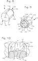
- the pressure-sensor device forming the subject of the invention, in the structure of which there can be identified two main parts, designated by 2 and 3: the part 2 basically performs functions of support and hydraulic connection, whilst the part 3 basically performs functions of lid and of electrical connection or connector.
- the bodies of the two parts 2 and 3 are coupled together, preferably in a sealed way, also for forming a casing of internal components of the device 1.
- the main body of the part 2, designated by 2a is preferably made of a relatively rigid material, such as for example a thermoplastic material or a metal material, and is traversed axially by a cavity or passage designated as a whole by 2b.
- a connection portion 4 As may be seen also in Figure 4 , identified in the body 2a are: a connection portion 4, an intermediate coupling portion 5 and a terminal portion 6.
- Said portion 4, which forms an inlet of the device, is designed to be connected to a hydraulic circuit (not represented), in which the fluid whose pressure is to be detected is located.
- the intermediate portion 5 comprises a flange-shaped wall, which extends radially towards the outside from the top of the connection portion 4. Rising from the aforesaid flange-shaped wall are an outer wall 5a and an inner wall 5b, having an annular configuration and being substantially coaxial with respect to one another.
- the wall 5a which is higher than the wall 5b, delimits a cavity or chamber - designated by CH in Figures 4 and 13 - located in which is a pressure-sensitive component, designated as a whole by 9; preferably, the chamber CH houses completely, or in any case a prevalent part of, the sensitive component 9.
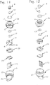
- the sensitive component 9 has a monolithic body, made, for example, of ceramic, or else plastic material, or else alumina, and is preferably cylindrical in shape. With reference to Figures 11-14 , defined in the body of the element 9 is a blind axial cavity 11, open on a first end face of the body itself, said cavity being delimited by a bottom surface and a peripheral or circumferential surface, designated, respectively, by 11a and 11b only in Figure 14 .
- a membrane portion designated, in the various cross-sectional views, by the reference 9a, integrated in which is a detection element, represented schematically with a dashed line only in Figures 11 and 13 , where it is designated by R.
- the detection element R is made or fixed on the second face 11, or on the side of the membrane 9a, external to the cavity 11.
- the detection element R can be represented by a preferably thin-film piezo-resistive element or, more in general, by any electrical or electronic component that is able to generate a signal being representative of a deformation or bending of the membrane portion 9a.
- the control circuit can be provided or integrated at least in part on the second end face 11c, preferably on a portion of greater thickness of the monolithic body of the element 9, and in particular its annular part around the membrane portion 9a.
- the aforesaid terminal portion 6 rising from the central region of the flange-shaped wall 5, in a position substantially coaxial to the walls 5a and 5b and to the connection portion 4, is the aforesaid terminal portion 6, having a generally cylindrical tubular shape, formed on the outside of which is a shoulder or seat for positioning of a sealing means 10, represented preferably by an O-ring. Said O-ring 10 is prearranged for forming a radial seal between the outer surface of the terminal portion 6 and the peripheral surface 11b of the cavity 11.
- the terminal portion 6 projects within the cavity 11 of the pressure-sensitive component 9 and mounted on its upper part a compensation element is mounted, designated by 12, having a predefined shape.
- This element 12 is made of a compressible material, so as to be able to offset or compensate possible increases of volume of the fluid undergoing detection, in the case of freezing thereof.
- the body of the compensation element 12 is made of a spongy or foamed material, preferably of an impermeable type with closed-cell, such as for example EPDM or silicone.
- the body of the element 12 can in any case be made in other ways, for example of an elastic material provided with a compressible chamber or internal portion.
- the compressible or compensation element 12 has a generally cylindrical tubular shape, with a central through hole, fitted in which is a terminal projection 14 of the tubular portion 6.
- the projection 14 is tubular, or is traversed by a respective part of the axial passage 2b of the body 2a.
- a respective portion 15 with a minimal passage section of the duct designed to deliver the fluid to the cavity 11 of the sensitive component 9.
- the upper end of the projection 14, designated by 14a only in Figure 7 is substantially configured as a flange in order to keep the compensation element 12 in the operative position.
- the projection 14 could, however, be absent, and the compensation element 12 could be fixed in another way to the tubular portion 6, for example glued, welded, or over-moulded.
- the upper surface of the compensation element 12 - designated by 12a only in Figure 13 - faces the bottom surface 11a of the membrane 9a for a significant part thereof, preferably for the most part or at least over 50% of the entire surface 11a.
- the distance between the surfaces 12a and 11a is preferably comprised between 0 and 5 mm, in particular between 0 and 0.5 mm. In the case of a solution that provides for a minimum distance, for example approximately 0.1 mm, between the surfaces 12a and 11a, there is the advantage of having little liquid undergoing freezing, or having a thin layer of liquid in contact with the membrane 9a, the percentage of expansion of which, following upon freezing, is negligible as compared to the capacity of bending of the membrane itself.
- the compensation element 12 there is preferably envisaged the use of a material of lower hardness, or such as to enable the fluid to penetrate and distribute as a thin film over the entire bottom surface 11a, by virtue of the elasticity or yielding of the material, and/or prevent at the same time perturbation of the operation or sensitivity of the membrane.
- the peripheral or circumferential surface of the compensation element 12 - designated by 12b only in Figure 13 - faces the peripheral surface 11b of the pressure-sensitive component 9.
- Said surface 12b is preferably at a distance from the surface 11b comprised between 0 and 2 mm, in particular between 0 and 0.5 mm.
- the diameter of the compensation element 12 is comprised between 8 and 10 mm; the compensation element 12 can also have a diameter greater than the diameter of the peripheral surface 11b, in order to enable an installation with interference fit or radial seal between the compensation element 12 and the peripheral surface 11b.
- the lower surface of the element 12 gives out into a chamber 30, described hereinafter (the lower surface of the element 12 is designated by 12c only in Figure 14 ).
- the compensation element 12 has at least one outer surface (i.e., different from the cylindrical one that delimits the corresponding central through hole) exposed to the fluid; in the case provided by way of example in the figure, the aforesaid surfaces 12a, 12b, 12c are all at least partially exposed to the fluid.
- the device 1 comprises a second compensation element of a predefined shape, built in a way and having a general function similar to that of the element 12.
- Said second compensation element, designated by 18, is housed in a part of the passage 2b of the body 2a that extends between the portions 4-6 (see, for example, Figures 4-6 ).
- the upper portion of the element 18 is at least in part fitted in a respective part of the passage 2b of intermediate diameter, substantially similar to the diameter of the element 18, whilst the bottom portion of the element 18 is located within a part of the passage 2b of the body 2a of larger or maximum diameter.
- the second compensation element 18 has an as a whole cylindrical shape, with an inner cavity 19 aligned axially to the cavity 15 of the projection 14, so as to define a respective part of the duct that carries the fluid being measured to the cavity 11 of the sensitive component 9; preferably, the cavity 19 has a section of passage larger than the axial cavity 15 of the projection 14.
- the compensation element 18 is kept within the passage 2b of the body 2a via a suitable positioning means, represented herein by an insert designated by 16.
- the insert 16 which is visible in detail in Figures 8 and 9 , is constituted by a rigid body, for example made of thermoplastic material, or metallic or mouldable material, with a generally cylindrical shape, having a lower part 16a that is massive or full, and an upper hollow part 16b.
- the hollow part 16b is delimited peripherally by a number of walls or tabs 16c, which rise from the top of the full part 16a, where the slits of separation 16d between the tabs proceed in the same full part in the form of axial grooves, designated by 16e.
- shaped projections 16f designed to define both resting surfaces for the compensation element 18 and channels 16g for passage of the fluid.
- at least two channels 16g are provided that criss-cross in the central region of the bottom of the hollow part 16b of the insert 16.
- the insert 16 is mounted (for example, fitted with interference fit) within the part of the passage 2b of the body 2a having a maximum section of passage, and in such a way that housed in its hollow part is the lower part of the compensation element 18, with the latter resting on the projections 16f.
- the tabs 16c are then contained between the outer surface of the element 18 and the inner surface of the corresponding part of passage 2b of the body 2a, as may be seen also in Figure 10 .
- the body of the part 3 for electrical connection has a hollow lower region, delimited by a bottom wall 20 and a peripheral wall 21, the end of which is configured for coupling between the walls 5a and 5b of the body 2a of the part 2.
- a tubular-body part 22 within which there extend terminals 23 for the electrical connection of the device 1.
- the terminals 23 are mounted in such a way that the respective lower end faces the inside of the cavity of the part 3 in order to be in contact with first contact elements 24a ( Figure 13 ) belonging to an electrical circuit designated as a whole by 24.
- the circuit 24 likewise comprises second contact elements, herein configured as metal pads or bushings 24b ( Figures 5 and 13 ), fitted and/or welded within which are the terminals 9b of the pressure-sensitive component 9.
- designated by 25 is a member for supporting the aforesaid circuit 24, which has pins 25a designed to bear upon purposely provided perimetral seats (one of which is designated by 9c in Figure 14 ) of the sensitive element 9, in particular for the purpose of providing a polarization or a precise mutual coupling.
- the pins 25a could have a substantially semicircular section.
- the cavity 11 of the pressure-sensitive component 9 is occupied by the terminal portion 6, provided at the top of which is the compensation element 12, which preferably occupies a significant portion of the cavity itself.
- the element 12 is kept in position via the projection 14, and in particular its flange portion 14a.
- said projection also defines the terminal portion 15 of the duct for delivery of the fluid, also including the portion 19 defined in the second compensation element 18.
- the presence of the seal or O-ring 10 delimits, within the cavity 11, a chamber 30 ( Figures 4 , 6 and 7 ), together with the exposed surfaces of the portion 6, the chamber of which is in fluid communication with the duct 15, 19 for delivery of the fluid.
- the fluid is represented schematically by the arrows. It should be considered that, in operative conditions, the fluid is undergoing only slight displacement, or it is in practically static conditions (consequently, also the ensuing references as regards the path followed by the fluid have the sole purpose of clarifying how the fluid itself can be in contact with or exert pressure on the membrane 9a of the pressure-sensitive component).
- the fluid penetrates or flows in the passage 2b of the body 2a via the inlet defined by the lower end of the passage itself.
- the axial grooves 16e formed in the lower part 16a of the insert 16 the fluid reaches the slits defined between the tabs 16c and then penetrates within the hollow part of the insert itself.
- the fluid can then occupy the channels defined between the projections 16f and thus reach the cavity 19 of the element 18.
- the fluid can in this way occupy also the cavity of the projection 14 and then the chamber 30 ( Figure 7 ); the pressure of the fluid then acts on the membrane portion 9a of the body of the sensitive component 9.
- the pressure of the fluid is not sufficient to cause a significant compression of the compensation elements 12 and 18, thus enabling at least one further compression for compensation in the case of freezing of the fluid.
- part of the fluid being measured can accumulate within the chamber 30 and within the duct of the fluid through the body 2a; in conditions of low ambient temperature, said accumulated fluid can freeze and thus increase in volume.
- the fact that the cavity 11 of the sensitive component 9 is occupied to a prevalent extent by the components referred to above has as a consequence that the useful volume in which the fluid can accumulate is reduced.
- the provision of minimum sections of passage determined by the grooves 16e, and/or the slits 16d, and/or the channels 16g ( Figure 10 ), has the function of determining preferential areas of start of freezing of the fluid within the corresponding duct.
- a similar function is performed, to a certain extent, also by the portion of duct 15 of small section, which is also in the immediate proximity of the compensation element 18 and/or the compensation element 12.
- the aforesaid ice plugs in the pipes 16e, 16d, 16g, 15 can form in the first steps of freezing of the fluid, contributing to countering any expansion due to the subsequent more extensive freezing of the fluid, in particular of the fluid present in portion of duct of larger section.
- said plugs can constitute a sort of "spontaneous barrier" both to prevent any further inflow of fluid into the areas that risk failure and to counter the thrust in the direction of the membrane 9a of frozen masses of significant volume.
- freezing of the fluid propagates from the stretch 15 in the direction of the membrane portion 9a, it will be the element 12 that intervenes, in the sense of compensating for the increase in volume of the limited part of fluid present in the chamber 30.
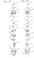
- Figures 15-20 Illustrated in Figures 15-20 is a first alternative embodiment of the device according to the invention.
- the reference numbers of Figures 1-14 are used to designate elements that are technically equivalent to the ones already described above.
- the means for positioning the compensation element 12 is represented by a tubular insert made of rigid material, for example thermoplastic or metal material, designated as a whole by 17.
- the rigid insert 17 has a tubular section 17a, partially inserted (for example via screwing) in a respective part of the passage 2b formed in the body 2a, and in particular a part of passage that traverses the portions 5 and 6 axially. Fitted on the region of the tubular part 17a that is not inserted in the portion 6 is the compensation element 12.
- the upper end of the insert 17, designated by 17b, is configured for keeping the element 12 or preventing it from sliding out upwards, and is at least partially positioned in a corresponding seat or recess on the upper face of the compensation element 12.
- the end 17b of the insert 17 is substantially formed by a series of radial projections (the element 17 could in any case be of a different shape, for example without said projections).
- a respective terminal portion of the duct that carries the fluid to the cavity of the sensitive component 9.
- said duct portion comprises two stretches, designated by A and B, having a different section of passage and being separated by an intermediate narrowed portion C, having a generally tapered shape.
- the stretch of duct A is preferably configured as capillary passage or duct.
- a washer element 13 is preferably provided, which, together with the shoulder designated by 6a in Figure 18 , delimits a seat for the seal or O-ring 10.
- the device 1 comprises a second compensation element 18, housed in a respective part of the axial passage 2b defined in the connection portion 4 of the body 2a.
- the second compensation element 18 has an as a whole cylindrical shape, with a through cavity 19 aligned axially to the insert 17 so as to define a respective part of the duct that carries the fluid being measured to the chamber 30.
- the cavity 11 of the component 9 is to a fair extent occupied by the terminal portion 6, provided at the top of which is the compensation element 12, kept in position via the insert 17.
- the insert 17 also defines the terminal stretch of the duct for the fluid, including also the stretch 19 defined in the second compensation element 18.
- the freezing of the fluid tends then to propagate or proceed towards the part of the duct B, C having a wider diameter, i.e., the part opposite to the membrane portion 9a.
- the presence of the second compensation element 18 further reduces the risks of damage to the device 1, since it enables compensation of the freezing of the fluid also on the opposite side with respect to the pressure-sensitive component.
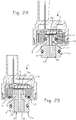
- FIG. 21-23 Illustrated in Figures 21-23 is a third embodiment of the device according to the invention. Also in said figures, the reference numbers of the previous figures are used to designate elements that are technically equivalent to the ones already described.
- the device 1 comprises just one compensation element 12 within the cavity 11 of the sensitive component 9.
- the body 2a has an axial passage 2b of diameter larger than that of the previous embodiments, within which both a compensation element 12 and a rigid insert, designated by 117, are inserted.
- the upper end of the terminal portion 6 is formed so as to prevent it from sliding out towards the outside of the compensation element 12.
- transverse diaphragms 6b which delimit a plurality of axial passages.
- the insert 117 is fitted from beneath into the body 2a so that positioned between its top and the diaphragms 6b is the element 12.
- the insert 117 has a protruding upper projection 117a ( Figures 22-23 ), traversed axially by a stretch of capillary duct A.
- the washer 13 is not envisaged.
- the insert 117 is kept in position via a bottom closing element, designated by 35, for example screwed or fitted in the stretch of passage 2b of the body 2a that extends in the connection portion 4.
- FIGS 24-27 are schematic cross-sectional illustrations of further possible embodiments of the invention. Also in said figures, the reference numbers of the previous figures are used to designate elements that are technically equivalent to the ones already described.
- the fourth embodiment of Figure 24 is conceptually similar to that of Figures 15-20 , but with the difference that, in this case, the insert 17 has a top flange portion 17b that is basically circular and having a reduced diameter, and does not define a stretch of capillary duct, or it comprises only a duct that is substantially equivalent to the aforesaid stretch of duct B.
- the washer 13 is not envisaged in so far as the seat for the seal or O-ring 10 is formed by a groove provided in the portion 6 of the body 2a.
- the two compensation elements 12 and 18 are configured in a single piece, designated as a whole by 40.
- an intermediate portion of the piece 40 of restricted diameter, so as to provide a groove in which a corresponding region of the portion 6 of the body 2a engages.
- the sealing means 10 operate between the face of the body of the sensitive component 9 onto which the cavity 11 opens, preferably a face that is at least in part plane, and the intermediate flange-shaped part 5 of the body 2a, also this part being provided with a face that is at least in part plane.
- the duct for delivery of the fluid is entirely formed in the piece 40.
- the piece 40 could be provided with an intermediate part, which connects the two compensation elements 12 and 18 and does not form a stretch of the duct for the fluid, said intermediate part being preferably at least partially within the portion 6 of the body 2a.
- the single piece 40 can be made separately and subsequently mounted on the body 2a, exploiting the elasticity of the material used.
- the piece 40 is obtained via moulding or over-moulding of material, preferably of a foamed type. Over-moulding is, for example, obtained directly on a part of the body 2a or of the casing of the device according to the invention, in particular at least partially inside of the portions 4, 6, or else on a corresponding insert.
- the intermediate part of the single piece 40 inside the portion 6 of the body 2a can for example be made of moulding material, which fills purposely provided channels present in the body 2a, said channels extending between the areas for housing the two compensation elements 12 and 18. Said channels are exploited for passage of the moulding material, which subsequently hardens and forms the aforesaid intermediate part.
- the piece 40 could, however, be moulded in another way, also for the purpose of providing corresponding projections or elements for fixing to the body 2a of the device 1.
- the body 2a could advantageously be provided with seats, projections, or channels, designed for passage and/or fixing of the moulding or over-moulding material.
- the body 2a can be made of a first material, for example a thermoplastic material, and the piece 40 of a second material, for example EPDM or silicone. After obtaining the body 2a with the first material, this is inserted in a suitable mould, within which the second material that is to form the piece 40 is subsequently injected.
- a first material for example a thermoplastic material
- a second material for example EPDM or silicone
- the mould can comprise, for example, at least one fixed part and at least one movable part, which are able to assume a working or closing position, and an opening position, according to modalities in themselves known.
- the parts have respective impressions shaped for defining as a whole a common cavity within the mould, when they are closed in the working position.
- Said cavity is in part occupied by the body 2a and is provided for receiving the material that is to form the piece 40, which as a whole has a shape designed to define, together with the axial passage 2b of the body 2a, the shape of said piece 40, with the corresponding axial duct.
- a possible sequence of moulding in order to obtain the body 2a with the over-moulded piece 40 could comprise for example the following steps:
- the cavity of the sensitive component 9 is occupied in part by the terminal portion 6 of the body 2a, on the top of which is positioned or fixed a compensation element 12, for example via gluing or welding or moulding.
- the compensation element can be kept in position, possibly slightly compressed, between a surface of the terminal portion 6 and at least one surface of the sensitive component 9.
- a second compensation element 18 which, however, could be absent.
- the duct for the fluid is formed in part by the axial cavity of the compensation elements 12, 18 and in part by a stretch of the axial passage 2b of the body 2a.
- the cavity of the sensitive component is instead prevalently occupied by a compensation element 12 with a thickness or height increased with respect to the previous embodiments.
- Said element 12 is positioned or fixed - for example via gluing - on the top of the portion 6, which in this case projects only to a minor extent within the aforesaid cavity 11; alternatively, the portion 6 could be outside the cavity 11 or even absent.
- the duct for delivering the fluid is formed in part by the axial cavities of the compensation elements 12 and 18 and in part by an intermediate stretch of the axial passage 2b of the body 2a.
- the sealing element 10 is mounted in a position similar to the one described with reference to the example of Figure 25 , i.e., between two substantially plane opposite faces of the sensitive element 9 and of the flange-shaped wall of the portion 5.
- a compensation element within the cavity of the sensitive component reduces considerably the risks of damage to the corresponding membrane portion and/or to the detection element associated thereto.
- the fact that said cavity is occupied to a substantial extent by the compensation element and/or by portions of the structure that supports the sensitive component reduces the volume allowed for stagnation of fluid subject to possible freezing.
- capillary passages or in any case passages of reduced section, in the fluid duct, when they are envisaged, makes it possible to impose beforehand, with a relative precision, one or more regions in which the fluid will start to freeze, with the possibility of subsequently developing freezing in the parts of duct with wider section, or in a direction opposite to the membrane portion of the sensitive component.
- the compensation element 12 could be prearranged also in order to provide the functions of the sealing element previously designated by 10.
- the element 12 could comprise at least one deformable peripheral part that performs functions of O-ring, of a diameter such as to be able to interfere decidedly with respect to the peripheral wall 11b of the pressure-sensitive component 9 and/or with parts of the body or casing of the device 1 and/or corresponding inserts.
- the compensation element or elements could be made of silicone, of a foamed or non-foamed type, or else silicone mixed with air bubbles, for example poured and left to harden in a mould or appropriate seat. Also using said material, the compensation elements can be configured in a single piece, and/or made separately and/or moulded over the body 2a.
- inserts provided for the body 2a for example the insert 17, can be moulded over the body itself, with modalities that are basically similar to the ones referred to above in relation to the over-moulding of the compensation element 12.
Landscapes
- Physics & Mathematics (AREA)
- General Physics & Mathematics (AREA)
- Chemical & Material Sciences (AREA)
- Analytical Chemistry (AREA)
- Measuring Fluid Pressure (AREA)
Priority Applications (1)
| Application Number | Priority Date | Filing Date | Title |
|---|---|---|---|
| PL12156088T PL2458362T3 (pl) | 2006-12-20 | 2007-12-18 | Urządzenie z czujnikiem ciśnienia |
Applications Claiming Priority (2)
| Application Number | Priority Date | Filing Date | Title |
|---|---|---|---|
| IT000906A ITTO20060906A1 (it) | 2006-12-20 | 2006-12-20 | Dispositivo sensore di pressione |
| EP07859223.5A EP2095083B1 (fr) | 2006-12-20 | 2007-12-18 | Dispositif capteur de pression |
Related Parent Applications (3)
| Application Number | Title | Priority Date | Filing Date |
|---|---|---|---|
| EP07859223.5 Division | 2007-12-18 | ||
| EP07859223.5A Division EP2095083B1 (fr) | 2006-12-20 | 2007-12-18 | Dispositif capteur de pression |
| EP07859223.5A Division-Into EP2095083B1 (fr) | 2006-12-20 | 2007-12-18 | Dispositif capteur de pression |
Publications (3)
| Publication Number | Publication Date |
|---|---|
| EP2458362A2 true EP2458362A2 (fr) | 2012-05-30 |
| EP2458362A3 EP2458362A3 (fr) | 2012-07-11 |
| EP2458362B1 EP2458362B1 (fr) | 2016-08-31 |
Family
ID=39433902
Family Applications (5)
| Application Number | Title | Priority Date | Filing Date |
|---|---|---|---|
| EP12156088.2A Active EP2458362B1 (fr) | 2006-12-20 | 2007-12-18 | Dispositif de capteur de pression |
| EP07859223.5A Active EP2095083B1 (fr) | 2006-12-20 | 2007-12-18 | Dispositif capteur de pression |
| EP12156084.1A Active EP2458361B1 (fr) | 2006-12-20 | 2007-12-18 | Dispositif de capteur de pression |
| EP12156079.1A Active EP2458360B1 (fr) | 2006-12-20 | 2007-12-18 | Dispositif de capteur de pression |
| EP15197152.0A Active EP3012609B1 (fr) | 2006-12-20 | 2007-12-18 | Dispositif de capteur de pression |
Family Applications After (4)
| Application Number | Title | Priority Date | Filing Date |
|---|---|---|---|
| EP07859223.5A Active EP2095083B1 (fr) | 2006-12-20 | 2007-12-18 | Dispositif capteur de pression |
| EP12156084.1A Active EP2458361B1 (fr) | 2006-12-20 | 2007-12-18 | Dispositif de capteur de pression |
| EP12156079.1A Active EP2458360B1 (fr) | 2006-12-20 | 2007-12-18 | Dispositif de capteur de pression |
| EP15197152.0A Active EP3012609B1 (fr) | 2006-12-20 | 2007-12-18 | Dispositif de capteur de pression |
Country Status (10)
| Country | Link |
|---|---|
| US (2) | US8051719B2 (fr) |
| EP (5) | EP2458362B1 (fr) |
| CN (1) | CN101611299B (fr) |
| BR (1) | BRPI0721074B1 (fr) |
| CA (2) | CA2670753C (fr) |
| ES (5) | ES2604343T3 (fr) |
| IT (1) | ITTO20060906A1 (fr) |
| MX (1) | MX2009006012A (fr) |
| PL (5) | PL2458360T3 (fr) |
| WO (1) | WO2008078184A2 (fr) |
Families Citing this family (35)
| Publication number | Priority date | Publication date | Assignee | Title |
|---|---|---|---|---|
| ITTO20080483A1 (it) * | 2008-06-19 | 2009-12-20 | Eltek Spa | Dispositivo sensore di pressione |
| ITTO20080484A1 (it) * | 2008-06-19 | 2009-12-20 | Eltek Spa | Dispositivo sensore di pressione |
| IT1391187B1 (it) * | 2008-08-01 | 2011-11-18 | Eltek Spa | Dispositivo sensore di pressione |
| EP2224218B1 (fr) * | 2009-02-25 | 2018-11-28 | Sensirion Automotive Solutions AG | Capteur dans un emballage moulé et son procédé de fabrication |
| DE102009050911B4 (de) * | 2009-10-26 | 2014-06-12 | Borgwarner Beru Systems Gmbh | Zylinderdrucksensor |
| SE534920C2 (sv) * | 2010-06-28 | 2012-02-14 | Tour & Andersson Ab | Ventilanordning till en differenstryckgivare med säkerhetsventil |
| JP2012073068A (ja) * | 2010-09-28 | 2012-04-12 | Fuji Electric Co Ltd | 圧力センサ用パッケージ |
| US9217685B2 (en) | 2010-12-27 | 2015-12-22 | Epcos Ag | Pressure sensor having a compressible element |
| EP2659248B1 (fr) * | 2010-12-27 | 2015-09-23 | Epcos AG | Capteur de pression à élément compressible |
| US8365607B2 (en) * | 2011-06-30 | 2013-02-05 | Sensata Technologies, Inc. | Anti-slip grooves in a crimped pressure sensor assembly |
| US8656786B2 (en) * | 2011-08-01 | 2014-02-25 | Honeywell International Inc. | Interchangeable pressure sensor assembly and methods of assembly |
| ITMI20120456A1 (it) | 2012-03-23 | 2013-09-24 | Microtel Tecnologie Elettroniche S P A | Sensore di pressione ceramico e relativo metodo di produzione, e trasduttore che incorpora un sensore di pressione ceramico |
| DE102012010979A1 (de) * | 2012-06-02 | 2013-12-05 | Hydac Electronic Gmbh | System zur Abgasnachbehandlung bei Verbrennungsmotoren |
| US9212963B2 (en) * | 2013-05-24 | 2015-12-15 | Barksdale, Inc. | Sensor water freeze protector |
| CN103344380A (zh) * | 2013-06-13 | 2013-10-09 | 安徽艾可蓝节能环保科技有限公司 | 一种抗冻陶瓷压力传感器封装 |
| US9581468B2 (en) * | 2014-01-31 | 2017-02-28 | DunAn Sensing, LLC | Methods for fabricating apparatus having a hermetic seal |
| JP6127009B2 (ja) * | 2014-03-26 | 2017-05-10 | 長野計器株式会社 | 物理量測定装置 |
| CN107250752B (zh) * | 2014-12-23 | 2021-03-30 | 埃尔特克有限公司 | 传感器装置,具体是压力传感器 |
| US10060814B2 (en) | 2016-03-15 | 2018-08-28 | Rosemount Inc. | Fluid filled elongate pressure sensor |
| CN107290099B (zh) | 2016-04-11 | 2021-06-08 | 森萨塔科技公司 | 压力传感器、用于压力传感器的插塞件和制造插塞件的方法 |
| ITUA20162833A1 (it) * | 2016-04-22 | 2017-10-22 | Eltek Spa | Dispositivo sensore, particolarmente un sensore di pressione |
| ITUA20162832A1 (it) * | 2016-04-22 | 2017-10-22 | Eltek Spa | Dispositivo sensore, particolarmente un sensore di pressione |
| JP6315025B2 (ja) * | 2016-04-26 | 2018-04-25 | 株式会社デンソー | 物理量センサおよびその製造方法 |
| JP6698044B2 (ja) * | 2017-03-17 | 2020-05-27 | 株式会社鷺宮製作所 | 圧力センサ |
| CN110608835B (zh) * | 2017-09-09 | 2021-03-09 | 山东东信岩土工程有限公司 | 岩土勘探工程软岩地应力测试装置和软岩地应力测试方法 |
| DE102017126121A1 (de) * | 2017-11-08 | 2019-05-09 | Tdk Electronics Ag | Drucksensorsystem mit Schutz vor einfrierendem Medium |
| IT201800001092A1 (it) | 2018-01-16 | 2019-07-16 | St Microelectronics Srl | Sensore di pressione piezoresistivo microelettromeccanico con capacita' di auto-diagnosi e relativo procedimento di fabbricazione |
| IT201800002751A1 (it) * | 2018-02-16 | 2019-08-16 | Eltek Spa | Dispositivo di rilevazione e/o controllo per apparecchi o sistemi a conduzione di liquido |
| US11105700B2 (en) * | 2018-05-15 | 2021-08-31 | Tyco Electronics Amp Korea Co., Ltd. | Snubber for pressure sensor and pressure sensor comprising the same |
| ES1218484Y (es) * | 2018-08-28 | 2018-12-27 | Cebi Electromechanical Components Spain S A | Dispositivo medidor de presion y temperatura de fluidos |
| US11118990B2 (en) * | 2019-06-21 | 2021-09-14 | Honeywell International Inc. | Micro-molded fluid pressure sensor housing |
| IT201900019274A1 (it) | 2019-10-18 | 2021-04-18 | Metallux Sa | Sensore di pressione |
| IT202000005389A1 (it) | 2020-03-12 | 2021-09-12 | Eltek Spa | Gruppo sensore di pressione, e relativi dispositivo e inserto |
| DE102020131299B3 (de) * | 2020-11-26 | 2021-10-07 | Ifm Electronic Gmbh | Druckmessgerät mit am Steckeranschluss vorgesehenem Luftdurchgang |
| EP4025029A1 (fr) * | 2021-01-05 | 2022-07-06 | MEAS France | Dispositif capteur et connexion de mise à la terre |
Citations (2)
| Publication number | Priority date | Publication date | Assignee | Title |
|---|---|---|---|---|
| WO1998031997A1 (fr) | 1997-01-21 | 1998-07-23 | Honeywell Inc. | Capteur de pression a piece rapportee compressible destinee a prevenir des dommages provoques par le gel |
| US20030140703A1 (en) | 2000-02-03 | 2003-07-31 | Manfred Weigl | Pressure sensor for detecting the pressure of a liquid |
Family Cites Families (4)
| Publication number | Priority date | Publication date | Assignee | Title |
|---|---|---|---|---|
| JPS5365089A (en) * | 1976-11-24 | 1978-06-10 | Toshiba Corp | Semiconductor pressure transducer |
| JP2503290B2 (ja) * | 1990-05-21 | 1996-06-05 | 株式会社日立製作所 | 半導体圧力・差圧測定ダイヤフラム |
| US5186055A (en) * | 1991-06-03 | 1993-02-16 | Eaton Corporation | Hermetic mounting system for a pressure transducer |
| IT1391187B1 (it) * | 2008-08-01 | 2011-11-18 | Eltek Spa | Dispositivo sensore di pressione |
-
2006
- 2006-12-20 IT IT000906A patent/ITTO20060906A1/it unknown
-
2007
- 2007-12-18 ES ES12156088.2T patent/ES2604343T3/es active Active
- 2007-12-18 CN CN2007800468202A patent/CN101611299B/zh active Active
- 2007-12-18 US US12/520,641 patent/US8051719B2/en active Active
- 2007-12-18 EP EP12156088.2A patent/EP2458362B1/fr active Active
- 2007-12-18 EP EP07859223.5A patent/EP2095083B1/fr active Active
- 2007-12-18 EP EP12156084.1A patent/EP2458361B1/fr active Active
- 2007-12-18 ES ES12156079.1T patent/ES2604325T3/es active Active
- 2007-12-18 EP EP12156079.1A patent/EP2458360B1/fr active Active
- 2007-12-18 ES ES15197152.0T patent/ES2644541T3/es active Active
- 2007-12-18 EP EP15197152.0A patent/EP3012609B1/fr active Active
- 2007-12-18 ES ES12156084.1T patent/ES2561407T3/es active Active
- 2007-12-18 PL PL12156079T patent/PL2458360T3/pl unknown
- 2007-12-18 MX MX2009006012A patent/MX2009006012A/es active IP Right Grant
- 2007-12-18 PL PL07859223T patent/PL2095083T3/pl unknown
- 2007-12-18 PL PL12156084T patent/PL2458361T3/pl unknown
- 2007-12-18 CA CA2670753A patent/CA2670753C/fr active Active
- 2007-12-18 PL PL15197152T patent/PL3012609T3/pl unknown
- 2007-12-18 WO PCT/IB2007/004154 patent/WO2008078184A2/fr active Application Filing
- 2007-12-18 PL PL12156088T patent/PL2458362T3/pl unknown
- 2007-12-18 BR BRPI0721074-4A patent/BRPI0721074B1/pt active IP Right Grant
- 2007-12-18 ES ES07859223.5T patent/ES2560249T3/es active Active
- 2007-12-18 CA CA2899849A patent/CA2899849C/fr active Active
-
2011
- 2011-09-23 US US13/200,323 patent/US8453513B2/en active Active
Patent Citations (2)
| Publication number | Priority date | Publication date | Assignee | Title |
|---|---|---|---|---|
| WO1998031997A1 (fr) | 1997-01-21 | 1998-07-23 | Honeywell Inc. | Capteur de pression a piece rapportee compressible destinee a prevenir des dommages provoques par le gel |
| US20030140703A1 (en) | 2000-02-03 | 2003-07-31 | Manfred Weigl | Pressure sensor for detecting the pressure of a liquid |
Also Published As
Similar Documents
| Publication | Publication Date | Title |
|---|---|---|
| EP2095083B1 (fr) | Dispositif capteur de pression | |
| EP2310822B1 (fr) | Dispositif de capteur de pression | |
| EP3237867B1 (fr) | Dispositif capteur, en particulier capteur de pression | |
| CN109416290B (zh) | 压力传感器装置 | |
| CN109196324B (zh) | 传感器装置,特别是压力传感器 | |
| JP2005351842A (ja) | 圧力センサ | |
| EP3446088A1 (fr) | Dispositif de capteur, en particulier capteur de pression |
Legal Events
| Date | Code | Title | Description |
|---|---|---|---|
| PUAI | Public reference made under article 153(3) epc to a published international application that has entered the european phase |
Free format text: ORIGINAL CODE: 0009012 |
|
| AC | Divisional application: reference to earlier application |
Ref document number: 2095083 Country of ref document: EP Kind code of ref document: P |
|
| AK | Designated contracting states |
Kind code of ref document: A2 Designated state(s): AT BE BG CH CY CZ DE DK EE ES FI FR GB GR HU IE IS IT LI LT LU LV MC MT NL PL PT RO SE SI SK TR |
|
| PUAL | Search report despatched |
Free format text: ORIGINAL CODE: 0009013 |
|
| AK | Designated contracting states |
Kind code of ref document: A3 Designated state(s): AT BE BG CH CY CZ DE DK EE ES FI FR GB GR HU IE IS IT LI LT LU LV MC MT NL PL PT RO SE SI SK TR |
|
| RIC1 | Information provided on ipc code assigned before grant |
Ipc: G01L 19/06 20060101AFI20120601BHEP Ipc: G01L 19/14 20060101ALI20120601BHEP Ipc: G01L 9/00 20060101ALI20120601BHEP |
|
| 17P | Request for examination filed |
Effective date: 20121224 |
|
| 17Q | First examination report despatched |
Effective date: 20150505 |
|
| GRAP | Despatch of communication of intention to grant a patent |
Free format text: ORIGINAL CODE: EPIDOSNIGR1 |
|
| INTG | Intention to grant announced |
Effective date: 20160411 |
|
| RAP1 | Party data changed (applicant data changed or rights of an application transferred) |
Owner name: ELTEK S.P.A. |
|
| GRAS | Grant fee paid |
Free format text: ORIGINAL CODE: EPIDOSNIGR3 |
|
| GRAA | (expected) grant |
Free format text: ORIGINAL CODE: 0009210 |
|
| AC | Divisional application: reference to earlier application |
Ref document number: 2095083 Country of ref document: EP Kind code of ref document: P |
|
| AK | Designated contracting states |
Kind code of ref document: B1 Designated state(s): AT BE BG CH CY CZ DE DK EE ES FI FR GB GR HU IE IS IT LI LT LU LV MC MT NL PL PT RO SE SI SK TR |
|
| REG | Reference to a national code |
Ref country code: CH Ref legal event code: EP Ref country code: GB Ref legal event code: FG4D |
|
| REG | Reference to a national code |
Ref country code: IE Ref legal event code: FG4D |
|
| REG | Reference to a national code |
Ref country code: DE Ref legal event code: R096 Ref document number: 602007047780 Country of ref document: DE |
|
| REG | Reference to a national code |
Ref country code: AT Ref legal event code: REF Ref document number: 825405 Country of ref document: AT Kind code of ref document: T Effective date: 20161015 |
|
| REG | Reference to a national code |
Ref country code: FR Ref legal event code: PLFP Year of fee payment: 10 |
|
| REG | Reference to a national code |
Ref country code: SE Ref legal event code: TRGR |
|
| REG | Reference to a national code |
Ref country code: LT Ref legal event code: MG4D |
|
| REG | Reference to a national code |
Ref country code: NL Ref legal event code: MP Effective date: 20160831 |
|
| PG25 | Lapsed in a contracting state [announced via postgrant information from national office to epo] |
Ref country code: LT Free format text: LAPSE BECAUSE OF FAILURE TO SUBMIT A TRANSLATION OF THE DESCRIPTION OR TO PAY THE FEE WITHIN THE PRESCRIBED TIME-LIMIT Effective date: 20160831 Ref country code: FI Free format text: LAPSE BECAUSE OF FAILURE TO SUBMIT A TRANSLATION OF THE DESCRIPTION OR TO PAY THE FEE WITHIN THE PRESCRIBED TIME-LIMIT Effective date: 20160831 |
|
| PG25 | Lapsed in a contracting state [announced via postgrant information from national office to epo] |
Ref country code: LV Free format text: LAPSE BECAUSE OF FAILURE TO SUBMIT A TRANSLATION OF THE DESCRIPTION OR TO PAY THE FEE WITHIN THE PRESCRIBED TIME-LIMIT Effective date: 20160831 Ref country code: NL Free format text: LAPSE BECAUSE OF FAILURE TO SUBMIT A TRANSLATION OF THE DESCRIPTION OR TO PAY THE FEE WITHIN THE PRESCRIBED TIME-LIMIT Effective date: 20160831 Ref country code: GR Free format text: LAPSE BECAUSE OF FAILURE TO SUBMIT A TRANSLATION OF THE DESCRIPTION OR TO PAY THE FEE WITHIN THE PRESCRIBED TIME-LIMIT Effective date: 20161201 |
|
| REG | Reference to a national code |
Ref country code: ES Ref legal event code: FG2A Ref document number: 2604343 Country of ref document: ES Kind code of ref document: T3 Effective date: 20170306 |
|
| PG25 | Lapsed in a contracting state [announced via postgrant information from national office to epo] |
Ref country code: RO Free format text: LAPSE BECAUSE OF FAILURE TO SUBMIT A TRANSLATION OF THE DESCRIPTION OR TO PAY THE FEE WITHIN THE PRESCRIBED TIME-LIMIT Effective date: 20160831 Ref country code: EE Free format text: LAPSE BECAUSE OF FAILURE TO SUBMIT A TRANSLATION OF THE DESCRIPTION OR TO PAY THE FEE WITHIN THE PRESCRIBED TIME-LIMIT Effective date: 20160831 |
|
| PG25 | Lapsed in a contracting state [announced via postgrant information from national office to epo] |
Ref country code: CZ Free format text: LAPSE BECAUSE OF FAILURE TO SUBMIT A TRANSLATION OF THE DESCRIPTION OR TO PAY THE FEE WITHIN THE PRESCRIBED TIME-LIMIT Effective date: 20160831 Ref country code: SK Free format text: LAPSE BECAUSE OF FAILURE TO SUBMIT A TRANSLATION OF THE DESCRIPTION OR TO PAY THE FEE WITHIN THE PRESCRIBED TIME-LIMIT Effective date: 20160831 Ref country code: BG Free format text: LAPSE BECAUSE OF FAILURE TO SUBMIT A TRANSLATION OF THE DESCRIPTION OR TO PAY THE FEE WITHIN THE PRESCRIBED TIME-LIMIT Effective date: 20161130 Ref country code: PT Free format text: LAPSE BECAUSE OF FAILURE TO SUBMIT A TRANSLATION OF THE DESCRIPTION OR TO PAY THE FEE WITHIN THE PRESCRIBED TIME-LIMIT Effective date: 20170102 Ref country code: DK Free format text: LAPSE BECAUSE OF FAILURE TO SUBMIT A TRANSLATION OF THE DESCRIPTION OR TO PAY THE FEE WITHIN THE PRESCRIBED TIME-LIMIT Effective date: 20160831 Ref country code: BE Free format text: LAPSE BECAUSE OF FAILURE TO SUBMIT A TRANSLATION OF THE DESCRIPTION OR TO PAY THE FEE WITHIN THE PRESCRIBED TIME-LIMIT Effective date: 20160831 |
|
| REG | Reference to a national code |
Ref country code: DE Ref legal event code: R097 Ref document number: 602007047780 Country of ref document: DE |
|
| PLBE | No opposition filed within time limit |
Free format text: ORIGINAL CODE: 0009261 |
|
| STAA | Information on the status of an ep patent application or granted ep patent |
Free format text: STATUS: NO OPPOSITION FILED WITHIN TIME LIMIT |
|
| REG | Reference to a national code |
Ref country code: CH Ref legal event code: PL |
|
| 26N | No opposition filed |
Effective date: 20170601 |
|
| PG25 | Lapsed in a contracting state [announced via postgrant information from national office to epo] |
Ref country code: SI Free format text: LAPSE BECAUSE OF FAILURE TO SUBMIT A TRANSLATION OF THE DESCRIPTION OR TO PAY THE FEE WITHIN THE PRESCRIBED TIME-LIMIT Effective date: 20160831 |
|
| PG25 | Lapsed in a contracting state [announced via postgrant information from national office to epo] |
Ref country code: MC Free format text: LAPSE BECAUSE OF FAILURE TO SUBMIT A TRANSLATION OF THE DESCRIPTION OR TO PAY THE FEE WITHIN THE PRESCRIBED TIME-LIMIT Effective date: 20160831 |
|
| REG | Reference to a national code |
Ref country code: IE Ref legal event code: MM4A |
|
| PG25 | Lapsed in a contracting state [announced via postgrant information from national office to epo] |
Ref country code: LI Free format text: LAPSE BECAUSE OF NON-PAYMENT OF DUE FEES Effective date: 20161231 Ref country code: LU Free format text: LAPSE BECAUSE OF NON-PAYMENT OF DUE FEES Effective date: 20161218 Ref country code: CH Free format text: LAPSE BECAUSE OF NON-PAYMENT OF DUE FEES Effective date: 20161231 |
|
| PG25 | Lapsed in a contracting state [announced via postgrant information from national office to epo] |
Ref country code: IE Free format text: LAPSE BECAUSE OF NON-PAYMENT OF DUE FEES Effective date: 20161218 |
|
| REG | Reference to a national code |
Ref country code: FR Ref legal event code: PLFP Year of fee payment: 11 |
|
| PG25 | Lapsed in a contracting state [announced via postgrant information from national office to epo] |
Ref country code: CY Free format text: LAPSE BECAUSE OF FAILURE TO SUBMIT A TRANSLATION OF THE DESCRIPTION OR TO PAY THE FEE WITHIN THE PRESCRIBED TIME-LIMIT Effective date: 20160831 Ref country code: HU Free format text: LAPSE BECAUSE OF FAILURE TO SUBMIT A TRANSLATION OF THE DESCRIPTION OR TO PAY THE FEE WITHIN THE PRESCRIBED TIME-LIMIT; INVALID AB INITIO Effective date: 20071218 |
|
| PG25 | Lapsed in a contracting state [announced via postgrant information from national office to epo] |
Ref country code: IS Free format text: LAPSE BECAUSE OF FAILURE TO SUBMIT A TRANSLATION OF THE DESCRIPTION OR TO PAY THE FEE WITHIN THE PRESCRIBED TIME-LIMIT Effective date: 20160831 |
|
| PG25 | Lapsed in a contracting state [announced via postgrant information from national office to epo] |
Ref country code: MT Free format text: LAPSE BECAUSE OF NON-PAYMENT OF DUE FEES Effective date: 20161218 |
|
| REG | Reference to a national code |
Ref country code: AT Ref legal event code: UEP Ref document number: 825405 Country of ref document: AT Kind code of ref document: T Effective date: 20160831 |
|
| P01 | Opt-out of the competence of the unified patent court (upc) registered |
Effective date: 20230529 |
|
| PGFP | Annual fee paid to national office [announced via postgrant information from national office to epo] |
Ref country code: GB Payment date: 20231219 Year of fee payment: 17 |
|
| PGFP | Annual fee paid to national office [announced via postgrant information from national office to epo] |
Ref country code: TR Payment date: 20231129 Year of fee payment: 17 Ref country code: SE Payment date: 20231222 Year of fee payment: 17 Ref country code: IT Payment date: 20231212 Year of fee payment: 17 Ref country code: FR Payment date: 20231226 Year of fee payment: 17 Ref country code: AT Payment date: 20231219 Year of fee payment: 17 |
|
| PGFP | Annual fee paid to national office [announced via postgrant information from national office to epo] |
Ref country code: PL Payment date: 20231123 Year of fee payment: 17 |
|
| PGFP | Annual fee paid to national office [announced via postgrant information from national office to epo] |
Ref country code: ES Payment date: 20240118 Year of fee payment: 17 |
|
| PGFP | Annual fee paid to national office [announced via postgrant information from national office to epo] |
Ref country code: DE Payment date: 20231227 Year of fee payment: 17 |