EP2458251B1 - Joint coulissant composite pour joints haute pression - Google Patents
Joint coulissant composite pour joints haute pression Download PDFInfo
- Publication number
- EP2458251B1 EP2458251B1 EP11190804.2A EP11190804A EP2458251B1 EP 2458251 B1 EP2458251 B1 EP 2458251B1 EP 11190804 A EP11190804 A EP 11190804A EP 2458251 B1 EP2458251 B1 EP 2458251B1
- Authority
- EP
- European Patent Office
- Prior art keywords
- seat
- hole
- gasket
- joint
- pipe
- Prior art date
- Legal status (The legal status is an assumption and is not a legal conclusion. Google has not performed a legal analysis and makes no representation as to the accuracy of the status listed.)
- Active
Links
- 239000002131 composite material Substances 0.000 title claims description 6
- 230000000284 resting effect Effects 0.000 claims description 16
- 230000008878 coupling Effects 0.000 claims description 12
- 238000010168 coupling process Methods 0.000 claims description 12
- 238000005859 coupling reaction Methods 0.000 claims description 12
- 230000006835 compression Effects 0.000 claims description 5
- 238000007906 compression Methods 0.000 claims description 5
- 239000012530 fluid Substances 0.000 claims description 5
- 238000003780 insertion Methods 0.000 claims description 4
- 230000037431 insertion Effects 0.000 claims description 4
- 239000000463 material Substances 0.000 claims description 4
- 239000002184 metal Substances 0.000 claims description 4
- 239000004033 plastic Substances 0.000 claims description 4
- 238000005520 cutting process Methods 0.000 description 3
- 238000007789 sealing Methods 0.000 description 3
- 230000000694 effects Effects 0.000 description 1
- 238000007689 inspection Methods 0.000 description 1
- 238000009434 installation Methods 0.000 description 1
- 238000003754 machining Methods 0.000 description 1
- 238000011179 visual inspection Methods 0.000 description 1
Images


Classifications
-
- F—MECHANICAL ENGINEERING; LIGHTING; HEATING; WEAPONS; BLASTING
- F16—ENGINEERING ELEMENTS AND UNITS; GENERAL MEASURES FOR PRODUCING AND MAINTAINING EFFECTIVE FUNCTIONING OF MACHINES OR INSTALLATIONS; THERMAL INSULATION IN GENERAL
- F16L—PIPES; JOINTS OR FITTINGS FOR PIPES; SUPPORTS FOR PIPES, CABLES OR PROTECTIVE TUBING; MEANS FOR THERMAL INSULATION IN GENERAL
- F16L37/00—Couplings of the quick-acting type
- F16L37/08—Couplings of the quick-acting type in which the connection between abutting or axially overlapping ends is maintained by locking members
- F16L37/084—Couplings of the quick-acting type in which the connection between abutting or axially overlapping ends is maintained by locking members combined with automatic locking
- F16L37/092—Couplings of the quick-acting type in which the connection between abutting or axially overlapping ends is maintained by locking members combined with automatic locking by means of elements wedged between the pipe and the frusto-conical surface of the body of the connector
- F16L37/0925—Couplings of the quick-acting type in which the connection between abutting or axially overlapping ends is maintained by locking members combined with automatic locking by means of elements wedged between the pipe and the frusto-conical surface of the body of the connector with rings which bite into the wall of the pipe
-
- F—MECHANICAL ENGINEERING; LIGHTING; HEATING; WEAPONS; BLASTING
- F16—ENGINEERING ELEMENTS AND UNITS; GENERAL MEASURES FOR PRODUCING AND MAINTAINING EFFECTIVE FUNCTIONING OF MACHINES OR INSTALLATIONS; THERMAL INSULATION IN GENERAL
- F16L—PIPES; JOINTS OR FITTINGS FOR PIPES; SUPPORTS FOR PIPES, CABLES OR PROTECTIVE TUBING; MEANS FOR THERMAL INSULATION IN GENERAL
- F16L13/00—Non-disconnectible pipe-joints, e.g. soldered, adhesive or caulked joints
- F16L13/14—Non-disconnectible pipe-joints, e.g. soldered, adhesive or caulked joints made by plastically deforming the material of the pipe, e.g. by flanging, rolling
- F16L13/141—Non-disconnectible pipe-joints, e.g. soldered, adhesive or caulked joints made by plastically deforming the material of the pipe, e.g. by flanging, rolling by crimping or rolling from the outside
- F16L13/143—Non-disconnectible pipe-joints, e.g. soldered, adhesive or caulked joints made by plastically deforming the material of the pipe, e.g. by flanging, rolling by crimping or rolling from the outside with a sealing element placed around the male part before crimping or rolling
-
- F—MECHANICAL ENGINEERING; LIGHTING; HEATING; WEAPONS; BLASTING
- F16—ENGINEERING ELEMENTS AND UNITS; GENERAL MEASURES FOR PRODUCING AND MAINTAINING EFFECTIVE FUNCTIONING OF MACHINES OR INSTALLATIONS; THERMAL INSULATION IN GENERAL
- F16L—PIPES; JOINTS OR FITTINGS FOR PIPES; SUPPORTS FOR PIPES, CABLES OR PROTECTIVE TUBING; MEANS FOR THERMAL INSULATION IN GENERAL
- F16L21/00—Joints with sleeve or socket
- F16L21/02—Joints with sleeve or socket with elastic sealing rings between pipe and sleeve or between pipe and socket, e.g. with rolling or other prefabricated profiled rings
- F16L21/035—Joints with sleeve or socket with elastic sealing rings between pipe and sleeve or between pipe and socket, e.g. with rolling or other prefabricated profiled rings placed around the spigot end before connection
-
- F—MECHANICAL ENGINEERING; LIGHTING; HEATING; WEAPONS; BLASTING
- F16—ENGINEERING ELEMENTS AND UNITS; GENERAL MEASURES FOR PRODUCING AND MAINTAINING EFFECTIVE FUNCTIONING OF MACHINES OR INSTALLATIONS; THERMAL INSULATION IN GENERAL
- F16L—PIPES; JOINTS OR FITTINGS FOR PIPES; SUPPORTS FOR PIPES, CABLES OR PROTECTIVE TUBING; MEANS FOR THERMAL INSULATION IN GENERAL
- F16L23/00—Flanged joints
- F16L23/16—Flanged joints characterised by the sealing means
- F16L23/18—Flanged joints characterised by the sealing means the sealing means being rings
-
- F—MECHANICAL ENGINEERING; LIGHTING; HEATING; WEAPONS; BLASTING
- F16—ENGINEERING ELEMENTS AND UNITS; GENERAL MEASURES FOR PRODUCING AND MAINTAINING EFFECTIVE FUNCTIONING OF MACHINES OR INSTALLATIONS; THERMAL INSULATION IN GENERAL
- F16L—PIPES; JOINTS OR FITTINGS FOR PIPES; SUPPORTS FOR PIPES, CABLES OR PROTECTIVE TUBING; MEANS FOR THERMAL INSULATION IN GENERAL
- F16L37/00—Couplings of the quick-acting type
- F16L37/08—Couplings of the quick-acting type in which the connection between abutting or axially overlapping ends is maintained by locking members
- F16L37/084—Couplings of the quick-acting type in which the connection between abutting or axially overlapping ends is maintained by locking members combined with automatic locking
- F16L37/092—Couplings of the quick-acting type in which the connection between abutting or axially overlapping ends is maintained by locking members combined with automatic locking by means of elements wedged between the pipe and the frusto-conical surface of the body of the connector
- F16L37/0926—Couplings of the quick-acting type in which the connection between abutting or axially overlapping ends is maintained by locking members combined with automatic locking by means of elements wedged between the pipe and the frusto-conical surface of the body of the connector with an inner support sleeve arranged within the pipe
-
- F—MECHANICAL ENGINEERING; LIGHTING; HEATING; WEAPONS; BLASTING
- F16—ENGINEERING ELEMENTS AND UNITS; GENERAL MEASURES FOR PRODUCING AND MAINTAINING EFFECTIVE FUNCTIONING OF MACHINES OR INSTALLATIONS; THERMAL INSULATION IN GENERAL
- F16L—PIPES; JOINTS OR FITTINGS FOR PIPES; SUPPORTS FOR PIPES, CABLES OR PROTECTIVE TUBING; MEANS FOR THERMAL INSULATION IN GENERAL
- F16L41/00—Branching pipes; Joining pipes to walls
- F16L41/08—Joining pipes to walls or pipes, the joined pipe axis being perpendicular to the plane of the wall or to the axis of another pipe
- F16L41/086—Joining pipes to walls or pipes, the joined pipe axis being perpendicular to the plane of the wall or to the axis of another pipe fixed with screws
-
- F—MECHANICAL ENGINEERING; LIGHTING; HEATING; WEAPONS; BLASTING
- F16—ENGINEERING ELEMENTS AND UNITS; GENERAL MEASURES FOR PRODUCING AND MAINTAINING EFFECTIVE FUNCTIONING OF MACHINES OR INSTALLATIONS; THERMAL INSULATION IN GENERAL
- F16L—PIPES; JOINTS OR FITTINGS FOR PIPES; SUPPORTS FOR PIPES, CABLES OR PROTECTIVE TUBING; MEANS FOR THERMAL INSULATION IN GENERAL
- F16L2201/00—Special arrangements for pipe couplings
- F16L2201/10—Indicators for correct coupling
Definitions
- the present invention relates to the sector of joints for high-pressure pipes, and in particular regards an innovative sliding gasket.
- the cross section of the gasket is compressed within the slot enabling sealing.
- the compression of the gasket occurs thanks to a chamfer made on the rim of the hole.
- the compressive stress depends upon the angle of the chamfer: the smaller the angle of the chamfer, the lower the compressive stress. For technological reasons, the angle of the chamfer cannot be less than 30°.
- the hole belongs to a pipe that needs to be cut to size, it happens that the hole is ovalized during the cutting operation, and the chamfer must be made at that moment, after cutting and prior to assembly.
- a tool must be used formed by an expander plug that calibrates the ovalized hole and by a mill that makes the chamfer.
- the compressive load on the gasket becomes very high, the sharp edge of the hole can damage the gasket or cause exit thereof from the seat, and the surface of the shaft that interferes with the ovalized hole can damage the inner surface of the hole jeopardizing fluid tightness of the joint.
- the patent No. EP1983245A1 regards a particular profile of the shaft that eliminates the interference between the hole and the gasket, but requires the inner surface of the hole to be deformed after assembly in order to compress the gasket radially.
- This solution solves the majority of the problems but only limitedly to the case where the hole of the pipe can be deformed easily.
- the deformation of the pipe (pressing) is a complex operation that requires particular equipment.
- DE 660 112 C discloses a joint according to the preamble of claim 1.
- the main purpose of the present invention is to overcome the aforesaid problems, to eliminate the conditions of malfunctioning of the gasket after assembly between the shaft and the hole, as well as to eliminate the need for calibrating, chamfering, and pressing tools.
- the purpose of the above is to enable correct and safe assembly without the need for particular equipment and in general reducing to a technically possible minimum the assembly load, moreover enabling an easy visual inspection of correct positioning of the gasket when assembly is completed.
- a composite gasket formed substantially by a rubber part and by a rigid ring (e.g., made of plastic, metal, etc.) - having function of flange - which is designed to draw the gasket itself from the resting position to the working position by the external pipe or hole that is axially fitted on the internal pipe or barbed fitting. Compression of the gasket that guarantees fluid tightness occurs thanks to the presence of a purposely provided conical area on the barbed fitting.
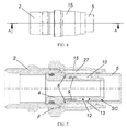
- a composite gasket 7 is provided, basically constituted by a rubber ring 9 fixedly coupled to a flange made of rigid material 8 (plastic or metal or some other suitable material), said gasket being designed to seal a coupling with play between a hollow shaft 4 and a hole 5 flowing within which is a pressurized fluid.
- the gasket 7 is designed for being housed in a circumferential seat 10 made on the outer surface of a hollow shaft or barbed fitting 4, which in what follows will be referred to also as "resting seat 10", in such a way that the outer diameter of the rubber ring 9 positioned in said seat 10 is smaller than or equal to the diameter of the shaft 4 itself and smaller than the diameter of the hole 5.
- the resting seat 10 is radiused by a conical ramp 12 to another portion of the shaft 4 that will be referred to as "working seat 11" of the gasket 7.
- the working seat 11 has a diameter that is greater than the diameter of the resting seat 10 and smaller than the diameter of the shaft 4 itself.
- the end of the shaft 4 to be inserted in the hole 5 envisages another portion with a specific function: the calibration seat SC.
- the calibration seat SC This is a frustoconical area with appropriate inclination suited to restoring the circularity of the hole of a pipe 5 cut to size, where the section of cut is ovalized.
- the calibration seat SC is joined to the adjacent resting seat 11 by means of a shoulder 13, resting on which is the edge of the rubber ring 9 to prevent accidental detachment of the gasket 7 from the barbed fitting 4.
- the front surface of the flange 8 is set bearing upon a purposely provided shoulder 14 with radial development, which juts out in a direction perpendicular to the end of the working seat 11.
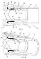
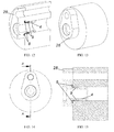
- a shaped sleeve 15 is provided, which, on the side facing the root of the barbed fitting 4, is provided with a fixing area and, on the opposite side, is provided with a conical seat sliding within which is a conical ring 27 with an internal toothing 16, designed to grip on the outer surface of the aforesaid external pipe 5 to prevent decoupling of the parts and consequent opening of the joint of the push-fit type 1a.
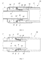
- said fixing area of the shaped sleeve 15 is designed to be fixed by clinching C ( Figures 2A-3B ), whereas in a variant of said first embodiment, said fixing area is provided with a thread F ( Figures 4 and 5 ),
- a further peculiar characteristic of the invention lies in that said shaped sleeve 15 is preferably provided with one or more through holes 19, which are uniformly distributed along a circumference and appropriately positioned in such a way that, when the joint is made, it is possible to verify proper positioning of the gasket 7 with respect to the barbed fitting 4 and to the pipe 5: if the joint is made correctly, visible from the holes 19 is a part of the rigid ring nut 8 and a part of the lateral surface of the external pipe 5 ( Figure 3B ).
- a second embodiment of the invention regards a joint of a press-fit type 1b, which, albeit envisaging axial insertion of the pipe or hollow shaft 4 in the hole 5, differs from the previous case in that, as an alternative to the shaped sleeve 15 described above, an outer tubular sleeve 17 is provided, which, after the sealed joint has been made by means of the axial coupling already described, is designed to undergo plastic deformation in a known way to press radially a purposely provided internal annular area of the pipe 5 against a gripping tooting 18 purposely provided on the outer surface of the calibration seat SC adjacent to the shoulder 13.
- the one or more through holes 19 already described are preferably provided.
- the invention enables an easy and safe assembly of a high-pressure joint without particular equipment for preparing the joint, which can be easily inspected.
- This gasket is particularly indicated for those connections between hollow shaft and hole of the push-fitting or press-block-fitting type.
- These joints enable joining of pipes by just manual pressure.
- the mechanical resistance of the joint is ensured by a deformable serrated ring that withholds the outer surface of the pipe 5.
- the assembly load in the solutions so far known can become particularly high, jeopardizing the advantages of practicality that these joints enable. Having available a gasket 7 according to the invention, which requires a minimal compressive load, becomes a determining factor.
- the sliding gasket 7 according to the invention is of general use, can be used for sealing connections provided with flanges or threaded ring nuts, and for both press-fit and push-fit connections.
- the equipment necessary for providing the sealed joint is minimal.
- the tool for cutting the pipes 5 that are to be cut to size it is necessary to have available simply what is prescribed by the particular system of mechanical connection.
- the present invention advantageously eliminates radically the problem of exit of the gasket from its own seat during installation of the pipe 5 on the barbed fitting 4.
- Another advantage lies in that the force of assembly of the pipe is considerably reduced.
- Yet a further advantage is that it does not require machining of the end of the pipe, such as calibration and deburring.
- a further advantage is that, if the end of the pipe is excessively ovalized, assembly would be impossible, thus guaranteeing a "fool-proof" effect.
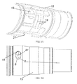
- a third embodiment of the invention concerns the case where the push-fit connection regards a constructional configuration in which the hole 5 is made in a wall instead of in a pipe.
- the barbed fitting 4 is fixed with respect to a front fixing element 28 designed to be constrained in a known way to the wall in which the hole 5 is present.
Landscapes
- Engineering & Computer Science (AREA)
- General Engineering & Computer Science (AREA)
- Mechanical Engineering (AREA)
- Gasket Seals (AREA)
- Joints With Pressure Members (AREA)
- Sliding-Contact Bearings (AREA)
- Flanged Joints, Insulating Joints, And Other Joints (AREA)
- Sealing Material Composition (AREA)
Claims (8)
- Raccord pour tubes à haute pression, caractérisé en ce qu'il comprend, en combinaison, un tube externe ou trou (5) conçu pour être monté axialement sur un tube interne ou embout cannelé (4), et un joint glissant composite (7) installé entre eux, dans lequel ledit joint glissant composite (7) est formé essentiellement par une partie en caoutchouc (9) et un anneau rigide (8) - ayant la fonction de bride - qui est conçu pour tirer le joint (7) lui-même d'une position ou siège de repos (10) à une position ou siège de travail (11) par ledit tube externe ou trou (5) qui est monté axialement sur ledit tube interne ou embout cannelé (4) de telle manière qu'une compression de la partie en caoutchouc (9) du joint (7), qui garantit une étanchéité au fluide, soit obtenue grâce à la présence d'une zone conique (12) prévue dans ce but spécifique sur l'embout cannelé (4) entre ledit siège de repos (10) et ledit siège de travail (11), dans lequel:- ladite partie en caoutchouc est essentiellement constituée par un anneau en caoutchouc (9) couplé de manière fixe à une bride coaxiale constituée de matériau rigide (8) en plastique ou métal ou un autre matériau approprié, ledit joint (7) étant conçu pour étanchéifier un accouplement avec jeu entre l'arbre creux ou tube interne (4) et le trou (5) à l'intérieur duquel un fluide sous pression peut s'écouler ;- ledit joint (7) est conçu pour être logé dans ledit siège de repos (10) qui est circonférentiel et est réalisé sur la surface extérieure de l'embout cannelé (4) de telle manière que le diamètre extérieur de l'anneau en caoutchouc (9) positionné dans ledit siège (10) soit inférieur ou égal au diamètre de l'embout cannelé (4) lui-même et inférieur au diamètre du trou (5) ;- ledit siège de repos (10) est arrondi par une rampe conique (12) vers le siège de travail (11) du joint (7) qui est disposé dans une autre portion de l'arbre (4) ; dans lequel le siège de travail (11) a un diamètre qui est supérieur au diamètre du siège de repos (10) et inférieur au diamètre de l'arbre (4) lui-même ;caractérisé en ce que
durant l'insertion dans la direction axiale de l'arbre (4) dans le trou (5), le rebord du trou (5) est conçu pour s'engager avec la bride (8), en déplaçant le joint (7) axialement le long de la rampe conique (12) du siège de repos (10) au siège de travail (11) ; en obtenant ainsi que l'anneau en caoutchouc (9) soit progressivement comprimé entre la surface intérieure du trou (5) et la surface extérieure de l'arbre (4) jusqu'à une compression maximale dans le siège de travail (11), en garantissant ainsi une étanchéité à la pression. - Raccord selon la revendication précédente, caractérisé en ce que l'extrémité de l'arbre (4) destinée à être insérée dans le trou (5) prévoit une autre portion qui fonctionne comme un siège de calibrage (SC), constitué par une zone tronconique avec inclinaison appropriée, adaptée pour rétablir la circularité du trou d'un tube coupé aux dimensions, là où la section de coupe est ovalisée.
- Raccord selon la revendication précédente, caractérisé en ce que le siège de calibrage (SC) est uni au siège de repos adjacent (10) au moyens d'un épaulement (13) sur lequel repose le bord de l'anneau en caoutchouc (9) de manière à empêcher un détachement accidentel du joint (7) par rapport à l'embout cannelé (4) .
- Raccord selon la revendication précédente, caractérisé en ce que, une fois que l'accouplement a été réalisé, la surface frontale de la bride (8) est mise en appui sur un épaulement prévu dans ce but spécifique (14) avec développement radial, qui fait saillie dans une direction perpendiculaire à l'extrémité du siège de travail (11).
- Raccord selon la revendication précédente, caractérisé en ce que, dans le cas où le trou (5) est réalisé à l'intérieur d'un tube externe, afin de fixer axialement les parties après leur accouplement pour obtenir le raccord, un manchon profilé (15) est prévu, lequel, du côté faisant face au pied de l'embout cannelé (4), est pourvu d'une zone de fixation et, du côté opposé, est muni d'un siège conique coulissant à l'intérieur duquel se trouve un anneau conique (27) avec une denture intérieure (16), conçue pour s'accrocher sur la surface extérieure du tube externe précité (5) pour empêcher le désaccouplement des parties et l'ouverture successive du raccord d'un type assemblé par poussée (1a) ; ladite zone de fixation étant bloquée axialement sur l'embout cannelé (4) au moyen d'un encliquetage (C) ou filetage (F) prévu dans ce but spécifique.
- Raccord selon la revendication précédente, caractérisé en ce que ledit manchon profilé (15) est pourvu d'un ou plusieurs trous passants (19), qui sont distribués uniformément le long d'une circonférence et positionnés de manière appropriée de manière que, quand le raccord est correctement réalisé, seule une partie de l'écrou annulaire rigide (8) et une partie de la surface latérale du tube externe (5) soient visibles de chaque trou (19).
- Raccord selon la revendication 4, caractérisé en ce que, dans le cas où le trou (5) est réalisé à l'intérieur d'un tube externe, de manière à fixer axialement les parties après leur accouplement pour obtenir le raccord, un manchon tubulaire extérieur (17) est prévu, lequel, après que le raccord étanche a été obtenu, est conçu pour être déformé plastiquement d'une manière connue pour presser une zone annulaire interne appropriée du tube (5) contre une denture de prise (18) disposée dans ce but spécifique sur la surface extérieure du siège de calibrage (SC) adjacent à l'épaulement (13).
- Raccord selon la revendication précédente, caractérisé en ce que ledit manchon extérieur (17) est pourvu d'un ou plusieurs trous passants (19), qui sont distribués uniformément le long d'une circonférence et positionnés de manière appropriée de manière que, quand le raccord est correctement réalisé, seule une partie de l'écrou annulaire rigide (8) et une partie de la surface latérale du tube externe (5) soient visibles de chaque trou (19).
Priority Applications (4)
| Application Number | Priority Date | Filing Date | Title |
|---|---|---|---|
| SI201130312T SI2458251T1 (sl) | 2010-11-25 | 2011-11-25 | Kompozitno drsno tesnilo za visokotlaäśne spojke |
| PL11190804T PL2458251T3 (pl) | 2010-11-25 | 2011-11-25 | Kompozytowa przesuwna uszczelka dla złączy wysokociśnieniowych |
| MEP-2014-144A ME02018B (me) | 2010-11-25 | 2011-11-25 | Kompozitna klizna zaptivka za spojeve pod visokim pritiskom |
| CY20141100945T CY1115739T1 (el) | 2010-11-25 | 2014-11-12 | Ενα συνθετικο ολισθαινον παρεμβυσμα για συναρμογες υψηλης πιεσης |
Applications Claiming Priority (1)
| Application Number | Priority Date | Filing Date | Title |
|---|---|---|---|
| ITMI2010A002190A IT1403583B1 (it) | 2010-11-25 | 2010-11-25 | Guarnizione composita a trascinamento per giunzioni di tubi ad alta pressione |
Publications (2)
| Publication Number | Publication Date |
|---|---|
| EP2458251A1 EP2458251A1 (fr) | 2012-05-30 |
| EP2458251B1 true EP2458251B1 (fr) | 2014-08-13 |
Family
ID=43742802
Family Applications (1)
| Application Number | Title | Priority Date | Filing Date |
|---|---|---|---|
| EP11190804.2A Active EP2458251B1 (fr) | 2010-11-25 | 2011-11-25 | Joint coulissant composite pour joints haute pression |
Country Status (11)
| Country | Link |
|---|---|
| EP (1) | EP2458251B1 (fr) |
| CY (1) | CY1115739T1 (fr) |
| DK (1) | DK2458251T3 (fr) |
| ES (1) | ES2523917T3 (fr) |
| HR (1) | HRP20141103T1 (fr) |
| IT (1) | IT1403583B1 (fr) |
| ME (1) | ME02018B (fr) |
| PL (1) | PL2458251T3 (fr) |
| PT (1) | PT2458251E (fr) |
| RS (1) | RS53636B1 (fr) |
| SI (1) | SI2458251T1 (fr) |
Families Citing this family (4)
| Publication number | Priority date | Publication date | Assignee | Title |
|---|---|---|---|---|
| CA2871341A1 (fr) * | 2012-04-24 | 2013-10-31 | Coes Company Srl | Joint d'etancheite coulissant composite pour joints haute pression |
| GB2505420B (en) * | 2012-08-28 | 2020-12-09 | Polypipe Ltd | Pipe insert |
| CN110007420B (zh) * | 2019-03-25 | 2020-06-12 | 中国科学院长春光学精密机械与物理研究所 | 一种薄壁密封筒的充放气装置 |
| GB2619053A (en) * | 2022-05-25 | 2023-11-29 | Aptiv Tech Ltd | Plug connector device and plug coding system |
Family Cites Families (8)
| Publication number | Priority date | Publication date | Assignee | Title |
|---|---|---|---|---|
| DE688252C (de) * | 1932-02-12 | 1940-02-16 | Eisenwerke Akt Ges Deutsche | Elastischer Dichtungsring fuer gusseiserne Muffenrohre mit Stopfbuechse |
| DE660112C (de) * | 1935-05-22 | 1938-05-18 | Buderus Eisenwerk | Muffenrohrverbindung |
| NL107650C (fr) * | 1956-05-28 | |||
| FR2740526B1 (fr) | 1995-10-30 | 1998-01-16 | Manuli Automobile France Sa | Joint d'etancheite composite pour raccordement etanche entre une extremite de tube et une piece, et ensemble piece/tube comportant un tel joint |
| US5803513A (en) * | 1996-06-13 | 1998-09-08 | Richardson; Robert J. | Restrained sealed bolted joints of fluid piping systems, inclusive of an improved gland, an added compression control ring, and/or added skid pads placed on a grip ring |
| US20100078937A1 (en) * | 2005-06-10 | 2010-04-01 | S & B Technical Products, Inc. | Self Restrained Ductile Iron Fitting |
| ITMI20070811A1 (it) | 2007-04-19 | 2008-10-20 | Co E S S P A | Raccordo a pressare, particolarmente per tubi multistrato. |
| DE202007009846U1 (de) * | 2007-07-12 | 2007-09-13 | Reinert-Ritz Gmbh | Zugfeste Rohrverbindung |
-
2010
- 2010-11-25 IT ITMI2010A002190A patent/IT1403583B1/it active
-
2011
- 2011-11-25 ME MEP-2014-144A patent/ME02018B/me unknown
- 2011-11-25 SI SI201130312T patent/SI2458251T1/sl unknown
- 2011-11-25 PL PL11190804T patent/PL2458251T3/pl unknown
- 2011-11-25 DK DK11190804.2T patent/DK2458251T3/en active
- 2011-11-25 EP EP11190804.2A patent/EP2458251B1/fr active Active
- 2011-11-25 RS RS20140623A patent/RS53636B1/en unknown
- 2011-11-25 ES ES11190804.2T patent/ES2523917T3/es active Active
- 2011-11-25 PT PT111908042T patent/PT2458251E/pt unknown
-
2014
- 2014-11-12 CY CY20141100945T patent/CY1115739T1/el unknown
- 2014-11-13 HR HRP20141103AT patent/HRP20141103T1/hr unknown
Also Published As
| Publication number | Publication date |
|---|---|
| ES2523917T3 (es) | 2014-12-02 |
| HRP20141103T1 (hr) | 2015-01-02 |
| DK2458251T3 (en) | 2014-11-17 |
| SI2458251T1 (sl) | 2014-12-31 |
| ME02018B (me) | 2015-05-20 |
| IT1403583B1 (it) | 2013-10-31 |
| CY1115739T1 (el) | 2017-01-25 |
| PT2458251E (pt) | 2014-11-21 |
| EP2458251A1 (fr) | 2012-05-30 |
| PL2458251T3 (pl) | 2015-01-30 |
| RS53636B1 (en) | 2015-04-30 |
| ITMI20102190A1 (it) | 2012-05-26 |
Similar Documents
| Publication | Publication Date | Title |
|---|---|---|
| CA2871341A1 (fr) | Joint d'etancheite coulissant composite pour joints haute pression | |
| US9631746B2 (en) | Coupling with tongue and groove | |
| EP2629902B1 (fr) | Raccord, en particulier pour conduites de réfrigération | |
| US10359132B2 (en) | Press fitting for a threaded connection and method for attaching a fitting to a threaded connection | |
| EP2110593B1 (fr) | Procédé de raccordement de tuyau et agencement de connecteur | |
| CA2972101C (fr) | Raccord d'emboutissage | |
| US9651177B2 (en) | Coupling connection for corrugated pipes | |
| US20110204624A1 (en) | Universal connection socket | |
| EP2458251B1 (fr) | Joint coulissant composite pour joints haute pression | |
| EP2061985B1 (fr) | Raccord de tuyau souple | |
| CA2682038A1 (fr) | Piece de fixation etanche pour tube en acier inoxydable | |
| EP3115655B1 (fr) | Joint c métallique intégré avec adaptateur fileté | |
| US20070013189A1 (en) | Sealing fitting for stainless steel tubing | |
| EP1983245B1 (fr) | Procédé de fourniture d'un raccord à sertissage, particulièrement pour tuyaux multicouches | |
| US5842726A (en) | Preformed transition pipe coupling | |
| CA2324175A1 (fr) | Raccord pivotant et technique de fixation d'un ecrou orientable a un raccord droit de vidange | |
| US7121595B2 (en) | Device for leaktight coupling of a tube to a threaded tubular nose | |
| US20120169046A1 (en) | Pipe coupling assembly | |
| EP4198365A1 (fr) | Raccord pour fluide à soufflet dynamique | |
| US20080042438A1 (en) | Hydraulic fitting and method of manufacture |
Legal Events
| Date | Code | Title | Description |
|---|---|---|---|
| PUAI | Public reference made under article 153(3) epc to a published international application that has entered the european phase |
Free format text: ORIGINAL CODE: 0009012 |
|
| AK | Designated contracting states |
Kind code of ref document: A1 Designated state(s): AL AT BE BG CH CY CZ DE DK EE ES FI FR GB GR HR HU IE IS IT LI LT LU LV MC MK MT NL NO PL PT RO RS SE SI SK SM TR |
|
| AX | Request for extension of the european patent |
Extension state: BA ME |
|
| 17P | Request for examination filed |
Effective date: 20120713 |
|
| 17Q | First examination report despatched |
Effective date: 20120917 |
|
| GRAP | Despatch of communication of intention to grant a patent |
Free format text: ORIGINAL CODE: EPIDOSNIGR1 |
|
| INTG | Intention to grant announced |
Effective date: 20140313 |
|
| RIN1 | Information on inventor provided before grant (corrected) |
Inventor name: BIZZARRINI, GIUSEPPE |
|
| GRAS | Grant fee paid |
Free format text: ORIGINAL CODE: EPIDOSNIGR3 |
|
| GRAA | (expected) grant |
Free format text: ORIGINAL CODE: 0009210 |
|
| AK | Designated contracting states |
Kind code of ref document: B1 Designated state(s): AL AT BE BG CH CY CZ DE DK EE ES FI FR GB GR HR HU IE IS IT LI LT LU LV MC MK MT NL NO PL PT RO RS SE SI SK SM TR |
|
| AX | Request for extension of the european patent |
Extension state: BA ME |
|
| REG | Reference to a national code |
Ref country code: GB Ref legal event code: FG4D |
|
| REG | Reference to a national code |
Ref country code: CH Ref legal event code: EP Ref country code: AT Ref legal event code: REF Ref document number: 682449 Country of ref document: AT Kind code of ref document: T Effective date: 20140815 |
|
| REG | Reference to a national code |
Ref country code: IE Ref legal event code: FG4D |
|
| RIN2 | Information on inventor provided after grant (corrected) |
Inventor name: BIZZARRINI, GIUSEPPE |
|
| REG | Reference to a national code |
Ref country code: DE Ref legal event code: R096 Ref document number: 602011009032 Country of ref document: DE Effective date: 20140925 |
|
| REG | Reference to a national code |
Ref country code: RO Ref legal event code: EPE |
|
| REG | Reference to a national code |
Ref country code: HR Ref legal event code: TUEP Ref document number: P20141103 Country of ref document: HR |
|
| REG | Reference to a national code |
Ref country code: CH Ref legal event code: NV Representative=s name: P&TS SA, CH |
|
| REG | Reference to a national code |
Ref country code: DK Ref legal event code: T3 Effective date: 20141113 |
|
| REG | Reference to a national code |
Ref country code: PT Ref legal event code: SC4A Free format text: AVAILABILITY OF NATIONAL TRANSLATION Effective date: 20141113 |
|
| REG | Reference to a national code |
Ref country code: ES Ref legal event code: FG2A Ref document number: 2523917 Country of ref document: ES Kind code of ref document: T3 Effective date: 20141202 Ref country code: SE Ref legal event code: TRGR |
|
| REG | Reference to a national code |
Ref country code: NL Ref legal event code: T3 |
|
| REG | Reference to a national code |
Ref country code: HR Ref legal event code: T1PR Ref document number: P20141103 Country of ref document: HR |
|
| REG | Reference to a national code |
Ref country code: NO Ref legal event code: T2 Effective date: 20140813 |
|
| REG | Reference to a national code |
Ref country code: EE Ref legal event code: FG4A Ref document number: E009953 Country of ref document: EE Effective date: 20141112 |
|
| PGFP | Annual fee paid to national office [announced via postgrant information from national office to epo] |
Ref country code: TR Payment date: 20141112 Year of fee payment: 4 |
|
| REG | Reference to a national code |
Ref country code: PL Ref legal event code: T3 |
|
| REG | Reference to a national code |
Ref country code: GR Ref legal event code: EP Ref document number: 20140402315 Country of ref document: GR Effective date: 20141223 |
|
| REG | Reference to a national code |
Ref country code: SK Ref legal event code: T3 Ref document number: E 17507 Country of ref document: SK |
|
| REG | Reference to a national code |
Ref country code: DE Ref legal event code: R097 Ref document number: 602011009032 Country of ref document: DE |
|
| REG | Reference to a national code |
Ref country code: HU Ref legal event code: AG4A Ref document number: E022501 Country of ref document: HU |
|
| PLBE | No opposition filed within time limit |
Free format text: ORIGINAL CODE: 0009261 |
|
| STAA | Information on the status of an ep patent application or granted ep patent |
Free format text: STATUS: NO OPPOSITION FILED WITHIN TIME LIMIT |
|
| PG25 | Lapsed in a contracting state [announced via postgrant information from national office to epo] |
Ref country code: MC Free format text: LAPSE BECAUSE OF FAILURE TO SUBMIT A TRANSLATION OF THE DESCRIPTION OR TO PAY THE FEE WITHIN THE PRESCRIBED TIME-LIMIT Effective date: 20140813 |
|
| 26N | No opposition filed |
Effective date: 20150515 |
|
| REG | Reference to a national code |
Ref country code: HR Ref legal event code: ODRP Ref document number: P20141103 Country of ref document: HR Payment date: 20151125 Year of fee payment: 5 |
|
| REG | Reference to a national code |
Ref country code: FR Ref legal event code: PLFP Year of fee payment: 5 |
|
| PGFP | Annual fee paid to national office [announced via postgrant information from national office to epo] |
Ref country code: FI Payment date: 20151125 Year of fee payment: 5 Ref country code: GB Payment date: 20151130 Year of fee payment: 5 Ref country code: NO Payment date: 20151209 Year of fee payment: 5 Ref country code: BG Payment date: 20151125 Year of fee payment: 5 Ref country code: DK Payment date: 20151126 Year of fee payment: 5 Ref country code: EE Payment date: 20151125 Year of fee payment: 5 Ref country code: GR Payment date: 20151127 Year of fee payment: 5 Ref country code: IE Payment date: 20151130 Year of fee payment: 5 |
|
| PGFP | Annual fee paid to national office [announced via postgrant information from national office to epo] |
Ref country code: PT Payment date: 20151125 Year of fee payment: 5 Ref country code: SE Payment date: 20151130 Year of fee payment: 5 Ref country code: LU Payment date: 20151202 Year of fee payment: 5 Ref country code: SI Payment date: 20151125 Year of fee payment: 5 Ref country code: BE Payment date: 20151127 Year of fee payment: 5 Ref country code: HR Payment date: 20151125 Year of fee payment: 5 Ref country code: SK Payment date: 20151125 Year of fee payment: 5 Ref country code: HU Payment date: 20151130 Year of fee payment: 5 Ref country code: ES Payment date: 20151229 Year of fee payment: 5 Ref country code: CZ Payment date: 20151125 Year of fee payment: 5 Ref country code: RO Payment date: 20151125 Year of fee payment: 5 Ref country code: IS Payment date: 20151125 Year of fee payment: 5 Ref country code: RS Payment date: 20151125 Year of fee payment: 5 |
|
| PG25 | Lapsed in a contracting state [announced via postgrant information from national office to epo] |
Ref country code: SM Free format text: LAPSE BECAUSE OF FAILURE TO SUBMIT A TRANSLATION OF THE DESCRIPTION OR TO PAY THE FEE WITHIN THE PRESCRIBED TIME-LIMIT Effective date: 20140813 |
|
| PGFP | Annual fee paid to national office [announced via postgrant information from national office to epo] |
Ref country code: AL Payment date: 20151126 Year of fee payment: 5 Ref country code: LT Payment date: 20160115 Year of fee payment: 5 |
|
| PGFP | Annual fee paid to national office [announced via postgrant information from national office to epo] |
Ref country code: LV Payment date: 20160226 Year of fee payment: 5 |
|
| PGFP | Annual fee paid to national office [announced via postgrant information from national office to epo] |
Ref country code: FR Payment date: 20160422 Year of fee payment: 15 |
|
| PGFP | Annual fee paid to national office [announced via postgrant information from national office to epo] |
Ref country code: PL Payment date: 20151125 Year of fee payment: 5 |
|
| PG25 | Lapsed in a contracting state [announced via postgrant information from national office to epo] |
Ref country code: BE Free format text: LAPSE BECAUSE OF NON-PAYMENT OF DUE FEES Effective date: 20161130 |
|
| REG | Reference to a national code |
Ref country code: HR Ref legal event code: PBON Ref document number: P20141103 Country of ref document: HR Effective date: 20161125 |
|
| REG | Reference to a national code |
Ref country code: FR Ref legal event code: PLFP Year of fee payment: 6 |
|
| REG | Reference to a national code |
Ref country code: LT Ref legal event code: MM4D Effective date: 20161125 |
|
| REG | Reference to a national code |
Ref country code: EE Ref legal event code: MM4A Ref document number: E009953 Country of ref document: EE Effective date: 20161130 |
|
| REG | Reference to a national code |
Ref country code: DK Ref legal event code: EBP Effective date: 20161130 Ref country code: NO Ref legal event code: MMEP |
|
| REG | Reference to a national code |
Ref country code: SE Ref legal event code: EUG |
|
| GBPC | Gb: european patent ceased through non-payment of renewal fee |
Effective date: 20161125 |
|
| PG25 | Lapsed in a contracting state [announced via postgrant information from national office to epo] |
Ref country code: CY Free format text: LAPSE BECAUSE OF NON-PAYMENT OF DUE FEES Effective date: 20161125 Ref country code: RO Free format text: LAPSE BECAUSE OF NON-PAYMENT OF DUE FEES Effective date: 20161125 Ref country code: EE Free format text: LAPSE BECAUSE OF NON-PAYMENT OF DUE FEES Effective date: 20161130 Ref country code: SK Free format text: LAPSE BECAUSE OF NON-PAYMENT OF DUE FEES Effective date: 20161125 Ref country code: HR Free format text: LAPSE BECAUSE OF NON-PAYMENT OF DUE FEES Effective date: 20161125 Ref country code: NO Free format text: LAPSE BECAUSE OF NON-PAYMENT OF DUE FEES Effective date: 20161130 Ref country code: LT Free format text: LAPSE BECAUSE OF NON-PAYMENT OF DUE FEES Effective date: 20161125 Ref country code: GR Free format text: LAPSE BECAUSE OF NON-PAYMENT OF DUE FEES Effective date: 20170612 Ref country code: IS Free format text: LAPSE BECAUSE OF FAILURE TO SUBMIT A TRANSLATION OF THE DESCRIPTION OR TO PAY THE FEE WITHIN THE PRESCRIBED TIME-LIMIT Effective date: 20170531 Ref country code: CZ Free format text: LAPSE BECAUSE OF NON-PAYMENT OF DUE FEES Effective date: 20161125 Ref country code: FI Free format text: LAPSE BECAUSE OF NON-PAYMENT OF DUE FEES Effective date: 20161125 |
|
| REG | Reference to a national code |
Ref country code: SK Ref legal event code: MM4A Ref document number: E 17507 Country of ref document: SK Effective date: 20161125 |
|
| REG | Reference to a national code |
Ref country code: IE Ref legal event code: MM4A |
|
| PG25 | Lapsed in a contracting state [announced via postgrant information from national office to epo] |
Ref country code: HU Free format text: LAPSE BECAUSE OF NON-PAYMENT OF DUE FEES Effective date: 20161126 Ref country code: LV Free format text: LAPSE BECAUSE OF NON-PAYMENT OF DUE FEES Effective date: 20161125 Ref country code: SE Free format text: LAPSE BECAUSE OF NON-PAYMENT OF DUE FEES Effective date: 20161126 Ref country code: RS Free format text: LAPSE BECAUSE OF NON-PAYMENT OF DUE FEES Effective date: 20170530 Ref country code: PT Free format text: LAPSE BECAUSE OF NON-PAYMENT OF DUE FEES Effective date: 20170525 Ref country code: SI Free format text: LAPSE BECAUSE OF NON-PAYMENT OF DUE FEES Effective date: 20161126 |
|
| PG25 | Lapsed in a contracting state [announced via postgrant information from national office to epo] |
Ref country code: LU Free format text: LAPSE BECAUSE OF NON-PAYMENT OF DUE FEES Effective date: 20161130 |
|
| REG | Reference to a national code |
Ref country code: SI Ref legal event code: KO00 Effective date: 20170804 |
|
| REG | Reference to a national code |
Ref country code: FR Ref legal event code: PLFP Year of fee payment: 7 |
|
| PG25 | Lapsed in a contracting state [announced via postgrant information from national office to epo] |
Ref country code: IE Free format text: LAPSE BECAUSE OF NON-PAYMENT OF DUE FEES Effective date: 20161125 Ref country code: DK Free format text: LAPSE BECAUSE OF NON-PAYMENT OF DUE FEES Effective date: 20161130 Ref country code: GB Free format text: LAPSE BECAUSE OF NON-PAYMENT OF DUE FEES Effective date: 20161125 |
|
| PGFP | Annual fee paid to national office [announced via postgrant information from national office to epo] |
Ref country code: DE Payment date: 20171130 Year of fee payment: 7 Ref country code: NL Payment date: 20171127 Year of fee payment: 7 |
|
| REG | Reference to a national code |
Ref country code: BE Ref legal event code: FP Effective date: 20141112 Ref country code: BE Ref legal event code: MM Effective date: 20161130 |
|
| PGFP | Annual fee paid to national office [announced via postgrant information from national office to epo] |
Ref country code: CH Payment date: 20171128 Year of fee payment: 7 Ref country code: AT Payment date: 20171127 Year of fee payment: 7 |
|
| PG25 | Lapsed in a contracting state [announced via postgrant information from national office to epo] |
Ref country code: PL Free format text: LAPSE BECAUSE OF NON-PAYMENT OF DUE FEES Effective date: 20161125 |
|
| PG25 | Lapsed in a contracting state [announced via postgrant information from national office to epo] |
Ref country code: ES Free format text: LAPSE BECAUSE OF NON-PAYMENT OF DUE FEES Effective date: 20161126 |
|
| PGFP | Annual fee paid to national office [announced via postgrant information from national office to epo] |
Ref country code: MK Payment date: 20151203 Year of fee payment: 5 |
|
| PG25 | Lapsed in a contracting state [announced via postgrant information from national office to epo] |
Ref country code: MK Free format text: LAPSE BECAUSE OF NON-PAYMENT OF DUE FEES Effective date: 20161126 |
|
| PG25 | Lapsed in a contracting state [announced via postgrant information from national office to epo] |
Ref country code: MT Free format text: LAPSE BECAUSE OF NON-PAYMENT OF DUE FEES Effective date: 20161125 |
|
| PGFP | Annual fee paid to national office [announced via postgrant information from national office to epo] |
Ref country code: MT Payment date: 20151125 Year of fee payment: 5 |
|
| REG | Reference to a national code |
Ref country code: ES Ref legal event code: FD2A Effective date: 20181030 |
|
| PG25 | Lapsed in a contracting state [announced via postgrant information from national office to epo] |
Ref country code: BG Free format text: LAPSE BECAUSE OF NON-PAYMENT OF DUE FEES Effective date: 20170808 |
|
| PG25 | Lapsed in a contracting state [announced via postgrant information from national office to epo] |
Ref country code: AL Free format text: LAPSE BECAUSE OF NON-PAYMENT OF DUE FEES Effective date: 20161125 |
|
| REG | Reference to a national code |
Ref country code: DE Ref legal event code: R119 Ref document number: 602011009032 Country of ref document: DE |
|
| REG | Reference to a national code |
Ref country code: CH Ref legal event code: PL |
|
| REG | Reference to a national code |
Ref country code: NL Ref legal event code: MM Effective date: 20181201 |
|
| REG | Reference to a national code |
Ref country code: AT Ref legal event code: MM01 Ref document number: 682449 Country of ref document: AT Kind code of ref document: T Effective date: 20181125 |
|
| PG25 | Lapsed in a contracting state [announced via postgrant information from national office to epo] |
Ref country code: CH Free format text: LAPSE BECAUSE OF NON-PAYMENT OF DUE FEES Effective date: 20181130 Ref country code: LI Free format text: LAPSE BECAUSE OF NON-PAYMENT OF DUE FEES Effective date: 20181130 Ref country code: NL Free format text: LAPSE BECAUSE OF NON-PAYMENT OF DUE FEES Effective date: 20181201 |
|
| PG25 | Lapsed in a contracting state [announced via postgrant information from national office to epo] |
Ref country code: DE Free format text: LAPSE BECAUSE OF NON-PAYMENT OF DUE FEES Effective date: 20190601 Ref country code: AT Free format text: LAPSE BECAUSE OF NON-PAYMENT OF DUE FEES Effective date: 20181125 Ref country code: FR Free format text: LAPSE BECAUSE OF NON-PAYMENT OF DUE FEES Effective date: 20181130 |
|
| PG25 | Lapsed in a contracting state [announced via postgrant information from national office to epo] |
Ref country code: TR Free format text: LAPSE BECAUSE OF NON-PAYMENT OF DUE FEES Effective date: 20161125 |
|
| PGFP | Annual fee paid to national office [announced via postgrant information from national office to epo] |
Ref country code: IT Payment date: 20231010 Year of fee payment: 13 |