EP2457680A2 - Consumable electrode type welding method - Google Patents
Consumable electrode type welding method Download PDFInfo
- Publication number
- EP2457680A2 EP2457680A2 EP12000322A EP12000322A EP2457680A2 EP 2457680 A2 EP2457680 A2 EP 2457680A2 EP 12000322 A EP12000322 A EP 12000322A EP 12000322 A EP12000322 A EP 12000322A EP 2457680 A2 EP2457680 A2 EP 2457680A2
- Authority
- EP
- European Patent Office
- Prior art keywords
- welding
- wire
- welding wire
- speed
- torch
- Prior art date
- Legal status (The legal status is an assumption and is not a legal conclusion. Google has not performed a legal analysis and makes no representation as to the accuracy of the status listed.)
- Granted
Links
Images

Classifications
-
- B—PERFORMING OPERATIONS; TRANSPORTING
- B23—MACHINE TOOLS; METAL-WORKING NOT OTHERWISE PROVIDED FOR
- B23K—SOLDERING OR UNSOLDERING; WELDING; CLADDING OR PLATING BY SOLDERING OR WELDING; CUTTING BY APPLYING HEAT LOCALLY, e.g. FLAME CUTTING; WORKING BY LASER BEAM
- B23K9/00—Arc welding or cutting
- B23K9/12—Automatic feeding or moving of electrodes or work for spot or seam welding or cutting
- B23K9/124—Circuits or methods for feeding welding wire
- B23K9/125—Feeding of electrodes
-
- B—PERFORMING OPERATIONS; TRANSPORTING
- B23—MACHINE TOOLS; METAL-WORKING NOT OTHERWISE PROVIDED FOR
- B23K—SOLDERING OR UNSOLDERING; WELDING; CLADDING OR PLATING BY SOLDERING OR WELDING; CUTTING BY APPLYING HEAT LOCALLY, e.g. FLAME CUTTING; WORKING BY LASER BEAM
- B23K9/00—Arc welding or cutting
- B23K9/06—Arrangements or circuits for starting the arc, e.g. by generating ignition voltage, or for stabilising the arc
- B23K9/067—Starting the arc
- B23K9/0671—Starting the arc by means of brief contacts between the electrodes
-
- B—PERFORMING OPERATIONS; TRANSPORTING
- B23—MACHINE TOOLS; METAL-WORKING NOT OTHERWISE PROVIDED FOR
- B23K—SOLDERING OR UNSOLDERING; WELDING; CLADDING OR PLATING BY SOLDERING OR WELDING; CUTTING BY APPLYING HEAT LOCALLY, e.g. FLAME CUTTING; WORKING BY LASER BEAM
- B23K9/00—Arc welding or cutting
- B23K9/16—Arc welding or cutting making use of shielding gas
- B23K9/173—Arc welding or cutting making use of shielding gas and of a consumable electrode
Definitions
- the present invention relates to a consumable electrode type welding method for generating an arc between a welding wire serving as a consumable electrode and a welding base metal serving as a member to be welded to thereby control the welding output.
- a robot manipulator is moved to thereby move a welding torch to a previously instructed welding start position and after then, while the feeding of the welding wire remains stopped, the welding torch is moved substantially in the welding wire feed direction by the robot manipulator to thereby allow the leading end of the welding wire to approach the member to be welded; if it is detected that the welding wire leading end has come into contact with the member to be welded, an initial current of a preset small current value is applied from a welding power supply device and, at the same time, the welding torch is moved in the opposite direction to the substantially welding wire feed direction to thereby carry out the retreating movement of the welding torch which moves the welding wire leading end away from the member to be welded; if the welding wire leading end and the member to be welded are moved away from each other due to the retreating movement of the welding torch, there is generated
- Fig. 5 is a schematic block diagram of the whole of a welding system for enforcing the above-mentioned consumable electrode type welding method using a robot.
- reference character 101 designates a welding wire used as a consumable electrode; and, the welding wire 101 can be played out from a wire spool 102 in the direction of a welding torch 104 by a wire feed motor 103.
- Reference numeral 105 stands for a welding power supply device.
- the welding power supply device 105 applies a given welding current I and a given welding voltage V, through the welding torch 104 and welding tip 106, into between the welding wire 101 and a base metal 107 serving as a member to be welded to thereby generate an arc 108 and control the wire feed motor 103 for enforcing the welding operation.
- Reference numeral 109 designates a robot manipulator.
- the robot manipulator 109 holds the welding torch 104, positions the torch 104 at a welding start position (not shown) and moves the welding torch 104 along a welding line (not shown). Also, the robot manipulator 109 is controlled by a robot control unit 110.
- the robot control unit 110 executes a two-way communication S between the welding power supply device 105 and itself and thus the robot control unit 110 sends welding conditions such as the welding current I and welding voltage V as well as instruction signals such as a welding start signal and a welding end signal.
- TS0' designates a timing when a welding start signal is transmitted from the robot control unit 110 to the welding power supply device 105, while TS1'- TS5'following TS0' stand for timings in the course of time respectively.
- the robot control unit 110 not only transmits a welding start signal to the welding power supply device 105 but also actuates the robot manipulator 109 to accelerate the welding torch 104 toward the base metal 107. And, when the speed of the welding torch 104 reaches an initial torch speed TV0, the robot control unit 110 causes the acceleration of the robot manipulator 109 to stop and continues the lowering motion of the welding torch 104 at a constant speed.
- the welding power supply device 105 when receiving the welding start signal from the robot control unit 110, applies a no-load voltage V0'into between the welding wire 101 and base metal 107.
- short circuit detect means (not shown) provided in the inside of the welding power supply device 105 outputs a short circuit signal A/S.
- This short circuit detect signal A/S is transmitted through the two-way communication S to the robot control unit 110 and thus the robot control unit 110 reduces and stops the robot manipulator 109 immediately, so that, at the timing TS2', the operation of the robot manipulator 109 is caused to stop, that is, the speed of the welding torch 104 becomes zero.
- the robot control unit 110 immediately reverses the operation of the robot manipulator 109 and starts the operation thereof in a direction where the welding torch 104 is pulled apart from the base metal 107, thereby lifting the welding torch 104.
- the period extending from the timing TS1' to TS3' is a short circuit period and, in this period, during the time until the timing TS2 where the robot manipulator 109 reduces down to zero, the welding wire 101 is pressed against the base metal 107; but, from the timing TS2'on, since the operation of the robot manipulator 109 is reversed, the pressing amount of the welding wire 101 decreases and thus, at the timing TS3', the short circuit is removed.
- the timing that is, the timing TS3'occurs at the time when the area of a triangle cde, which is shown by the line of the speed TV of the welding torch and expresses the lifting amount of the welding wire 101, exceeds the area of a triangle abc which is shown by the line of the speed TV of the welding torch for expressing the pressing amount of the welding wire 101.
- the welding power supply device 105 controls the welding current I at II', and then increases the current up to 12' after passage of a given time and waits for the opening of the short circuit.
- the welding current is controlled to 11' which is set relatively low.
- the reason for this is to avoid a possibility that, owing to the initial short circuit, the leading end portion of the welding wire is heated due to Joule effect to melt the wire and thus, simultaneously with generation of the arc, the molten welding wire can spatter around to form spatters.
- the welding power supply device 105 actuates the wire feed motor 103 to accelerate the welding wire 101 toward the base metal 107, continues the acceleration until the speed of the welding wire 101 reaches a welding wire speed (not shown) for actual welding, and, after the welding wire speed reaches the welding wire speed for actual welding, continues the feeding of the welding wire at a constant speed.
- the welding power supply device 105 controls the current to a second initial current 14 and, after then, controls the current to an output for actual welding (not shown).
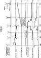
- description will be given below of a welding end time in the above-mentioned consumable electrode type welding method in the welding system with reference to a timing chart shown in Fig. 7 .
- Fig. 6 specifically, in the vertical, direction thereof there are shown the respective states of the moving speed of the welding torch TV, the feeding speed of the welding wire WF and a welding output P, whereas the horizontal axis thereof expresses time.
- TEO' designates a timing when a welding end signal is transmitted from the robot control unit 110 to the welding power supply device 105, while TE1' - TE4' following TE0' stand for timings in the course of time respectively.
- the welding power supply device 105 controls the wire feed motor 103 to reduce the feed speed of the welding wire 101.
- the welding power supply device 105 reduces the welding output and, at a timing TE2' where a predetermined condition is satisfied, it controls the welding output to a constant welding output.
- This constant output P1 is referred to as a "burn-back".
- the welding power supply device 105 continues the burn-back at and from a timing TE3' where the welding wire 101 is caused to stop, that is, keeps the constant output to continue the ark 108 for a given period; and, after the welding wire 101 is burned up, the welding power supply device 105 stops the constant output at a timing TE4'.
- This "burn-back" control method is a widely used control method for preventing occurrence of a so called wire stick phenomenon in which the welding wire 101 is contacted with a molten pool (not shown) and is thereby fixed when the welding is ended.
- the conventional consumable electrode type welding method requires the reversing operation of the robot manipulator 109.
- the wire feed motor 103 is actuated for the first time after generation of the initial arc, the feed of the welding wire 101 is not be able to catch up with the melting speed of the welding wire 101 to thereby extend the length of the arc 108, resulting in the unstable arc 108.
- a consumable electrode type welding method in which, using a welding system comprising wire feed means for feeding a welding wire to a welding torch, an actuator for holding the welding torch and moving the welding torch, a control unit for driving and controlling the actuator, and a welding power supply device for applying a welding output into and between a member to be welded and the welding wire, the welding torch is moved by the actuator in a direction where the welding torch is pulled apart from the member to be welded while feeding the welding wire to thereby control the speed of the welding wire with respect to the member to be welded.
- the actuator can control the speed of the welding wire with respect to the member to be welded through a one-way operation, the response time and acceleration/reduction time can be reduced when compared with the conventional method, and also because the distance between the welding wire and the member to be welded can be controlled with a good following capability, an arc can be stabilized early.
- the "burn-back" processing time in the welding end time can also be reduced when compared with the conventional method.
- the actuator moves the welding torch in a direction where the welding torch is pulled apart from the welding wire to thereby allow an initial arc to occur with the welding wire separated from the member to be welded, not only the reversing operation is eliminated and thus the waste time is reduced to be thereby able to reduce the tact time, but also the arc in the welding start time can be stabilized to thereby reduce the "unexpected stop" effectively.
- Fig. 1 is a schematic block diagram of the outline of a welding system for enforcing the invention, in which reference character 1 designates a welding wire used as a consumable electrode to be played out in the direction of a welding torch 4 from a wire spool 2 by a wire feed motor 3.
- reference character 1 designates a welding wire used as a consumable electrode to be played out in the direction of a welding torch 4 from a wire spool 2 by a wire feed motor 3.
- 5 stands for a welding power supply device which applies a given welding current I and a given welding voltage V, through the welding torch 4 and a welding tip 6, into between the welding wire 1 and a base metal 7 used as a member to be welded to generate an arc and also controls the wire feed motor 3, thereby enforcing the welding operation.
- the robot control unit 10 executes a two-way communication S between the welding power supply device 5 and itself and transmits welding conditions such as the welding current I and welding voltage V as well as welding start and end instructions.
- TS0 designates a timing where a welding start signal is transmitted from the robot control unit 10 to the welding power supply device 5, while TS1 - TS5 respectively express timings following TS0.
- the welding power supply device 5 when the welding start signal is transmitted from the robot control unit 10 to the welding power supply device 5 (TS0), the welding power supply device 5 applies a no-load voltage V0 into between the welding wire 1 and base metal 7 and also actuates the wire feed motor 3 to thereby accelerate the welding wire 1 toward the base metal 7.
- the welding power supply device 5 causes the wire feed motor 3 to stop the acceleration of the welding wire but continues the wire feed at a constant speed.
- a short circuit signal A/S is output from short circuit detect means (not shown) which is provided in the inside of the welding power supply device 5.
- the short circuit detect signal A/S is transmitted through the two-way communication S to the robot control unit 10.
- the robot control unit 10 immediately actuates the robot manipulator 9 to start to move the welding torch 4 in a direction where the welding torch 4 is pulled substantially apart from the base metal 7 and also to lift the welding torch 4.
- a period from TS 1 to TS3 is a short circuit period and, during this period, the welding wire 1 is continuously fed at an initial wire speed W0 and the robot manipulator 9 continues to lift the welding torch 4. Therefore, the speed of the leading end portion of the welding wire 1 is a composite speed of the wire speed WF and torch speed TV as shown by a broken line in Fig. 2 .
- the leading end of the welding wire 1, at and after TS1 causes the welding wire 1 to be pressed against the base metal until TS2 where the composite speed shown by a broken line in Fig. 2 becomes zero; at and after TS2, the composite speed turns to a negative speed and thus the pressing amount decreases; and, at the timing TS3, the short circuit is opened.
- the timing TS3 occurs at the time when the wire lifting amount, that is, the area of a triangle hji exceeds the wire pressing amount or the area of a triangle fgh.
- the welding power supply device 5 controls the welding current I to turn to I1 and, after passage of a given time, increases the current up to 12 and waits for the opening of the short circuit.
- the reason why the welding current is controlled to I1 set relatively low as the first stage of the initial short circuit period is to prevent occurrence of a phenomenon that the wire can be molten due to the Joule heat of the wire leading end portion caused by the initial short circuit and thus the molten wire can spatter around simultaneously with generation of an arc.
- the reason why the welding current is varied from 11 to 12 is to be able to provide sufficient energy to generate an arc when the short circuit is opened at the timing TS3.
- Fig. 3 is an explanatory timing chart in which the wire speed WF according to the prior art shown by a broken line is overlapped on the same timing chart as shown in Fig. 2 according to the present embodiment, in order to be able to compare the invention with the prior art.
- the welding wire starts to accelerate for the first time. Therefore, for example, if the timings of the invention and prior art when the wire speed becomes WF4 are compared with each other, the prior art method is found slower by the time from TS4 to TS4'.
- the present embodiment when it is detected that the leading end of the welding wire 1 comes into contact with the base metal 7 used as the member to be welded, by lifting the welding torch 4 using the robot manipulator 9 while continuing the forward feed of the welding wire 1, an arc is generated in a state where the welding wire 1 is separated from the base metal 7.
- the welding power supply device 5 controls the wire feed motor 3 to reduce the speed of the welding wire.
- the welding output is also reduced and, at the timing TE1 where a predetermined condition is satisfied, the welding power supply device 5 transmits a start signal for lifting the welding torch 4 to the robot control unit 10.
- the robot control unit 10 On receiving the lifting operation start signal from the welding power supply device 5, the robot control unit 10 immediately controls the robot manipulator 9 to lift the welding torch 4.
- the speed of the leading end of the welding wire 1 becomes a composite speed of the wire speed WF and torch speed TV, that is, it becomes such speed as shown by a broken line in Fig. 4 .
- the speed of the welding wire 1 becomes zero with respect to the base metal 7, thereby being able to stop the welding output P.
- the operation of the welding wire 1 and the lifting operation of the welding torch 4 are executed continuously but, at the time when the area of a trapezoid klmn, which corresponds to the lifting distance of the welding torch 4, exceeds the area of a triangle opq corresponding to the inertial running distance of the welding wire 1 until it stops, there is eliminated a danger of the wire stick phenomenon in which the welding wire 1 is contacted with the molten pool of the base metal 7 and is thereby fixed. Therefore, the robot control unit 10 immediately controls the robot manipulator 9 so as to be able to switch over to a next operation (for example, an operation in which the manipulator 9 moves to the position of the welding torch at the welding start time for a next welding operation).
- a next operation for example, an operation in which the manipulator 9 moves to the position of the welding torch at the welding start time for a next welding operation.
- the tact time can be reduced quite effectively; and also, since there is prevented formation of a large ball-like fixed body in the leading end of the welding wire 1 due to the burn-up of the welding wire, there can be avoided an ill influence on the welding start for the next step.
- the lifting operation of the welding torch is carried out by the robot manipulator.
- an actuator separately and the lifting operation of the welding torch may be executed using this actuator.
- the welding torch may be positioned or may be moved along a welding line, which, of course, has no ill influence on the effects of the invention.
- a consumable electrode type welding method according to the invention not only can eliminate the need for the reverse operation of the robot manipulator to reduce the waste time to thereby be able to reduce the tact time but also can stabilize an arc in the welding start portion and reduce the "unexpected stop" effectively. Therefore, the invention is industrially useful as a consumable electrode type welding method which is used, for example, in production facilities and construction work.
Abstract
Description
- The present invention relates to a consumable electrode type welding method for generating an arc between a welding wire serving as a consumable electrode and a welding base metal serving as a member to be welded to thereby control the welding output.
- Recently, the welding industry has always made effort to further enhance the productivity of the welding operation in order to secure an international competitive ability. Especially, there have been increasing the need for a reduction in a so called "unexpected stop", which is a slight trouble causing the production line to stop, and the need for a reduction in the tact time more than before.
- As the reasons for the unexpected stop, there can be pointed out various reasons and the greatest reason is a trouble caused by fault in an arc start.
- In view of this, in a conventional consumable electrode type welding method, as a method for enforcing its arc start, there is known the following method: that is, when a start signal is input from the outside, a robot manipulator is moved to thereby move a welding torch to a previously instructed welding start position and after then, while the feeding of the welding wire remains stopped, the welding torch is moved substantially in the welding wire feed direction by the robot manipulator to thereby allow the leading end of the welding wire to approach the member to be welded; if it is detected that the welding wire leading end has come into contact with the member to be welded, an initial current of a preset small current value is applied from a welding power supply device and, at the same time, the welding torch is moved in the opposite direction to the substantially welding wire feed direction to thereby carry out the retreating movement of the welding torch which moves the welding wire leading end away from the member to be welded; if the welding wire leading end and the member to be welded are moved away from each other due to the retreating movement of the welding torch, there is generated an arc to which the initial current is applied and, while the initial arc generating state remains held, the retreating movement of the welding torch is allowed to continue; if the welding torch returns back to the welding start position, the retreating movement is switched over to the movement in the previously instructed welding direction and, at the same time, the feed of the welding wire is started and a steady-state welding current is applied, whereby the initial arc generating state is switched over to the steady-state arc generating stage. (For example, see the patent literature 1).
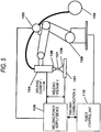
Now,Fig. 5 is a schematic block diagram of the whole of a welding system for enforcing the above-mentioned consumable electrode type welding method using a robot.
InFig. 5 ,reference character 101 designates a welding wire used as a consumable electrode; and, thewelding wire 101 can be played out from awire spool 102 in the direction of awelding torch 104 by awire feed motor 103.Reference numeral 105 stands for a welding power supply device. The weldingpower supply device 105 applies a given welding current I and a given welding voltage V, through thewelding torch 104 andwelding tip 106, into between thewelding wire 101 and abase metal 107 serving as a member to be welded to thereby generate anarc 108 and control thewire feed motor 103 for enforcing the welding operation.
Reference numeral 109 designates a robot manipulator. Therobot manipulator 109 holds thewelding torch 104, positions thetorch 104 at a welding start position (not shown) and moves thewelding torch 104 along a welding line (not shown).
Also, therobot manipulator 109 is controlled by arobot control unit 110. Therobot control unit 110 executes a two-way communication S between the weldingpower supply device 105 and itself and thus therobot control unit 110 sends welding conditions such as the welding current I and welding voltage V as well as instruction signals such as a welding start signal and a welding end signal. - Now, description will be given below of a consumable electrode type welding method used in the above-structured system with reference to a timing chart shown in
Fig. 6 . - Referring to
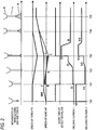
Fig. 6 specifically, in the vertical direction thereof, there are shown the respective states of the moving speed of the welding torch TV, the feeding speed of the welding wire WF, a short circuit detect signal A/S, a welding current I and a welding voltage V, whereas the horizontal axis thereof expresses time. In this illustration, as timings, TS0' designates a timing when a welding start signal is transmitted from therobot control unit 110 to the weldingpower supply device 105, while TS1'- TS5'following TS0' stand for timings in the course of time respectively. - Firstly, the
robot control unit 110 not only transmits a welding start signal to the weldingpower supply device 105 but also actuates therobot manipulator 109 to accelerate thewelding torch 104 toward thebase metal 107. And, when the speed of thewelding torch 104 reaches an initial torch speed TV0, therobot control unit 110 causes the acceleration of therobot manipulator 109 to stop and continues the lowering motion of thewelding torch 104 at a constant speed. - Also, when receiving the welding start signal from the
robot control unit 110, the weldingpower supply device 105 applies a no-load voltage V0'into between thewelding wire 101 andbase metal 107. - Then, at the timing TS1') if the
welding wire 101 is contacted with thebase metal 107, short circuit detect means (not shown) provided in the inside of the weldingpower supply device 105 outputs a short circuit signal A/S. - This short circuit detect signal A/S is transmitted through the two-way communication S to the
robot control unit 110 and thus therobot control unit 110 reduces and stops therobot manipulator 109 immediately, so that, at the timing TS2', the operation of therobot manipulator 109 is caused to stop, that is, the speed of thewelding torch 104 becomes zero. - After then, the
robot control unit 110 immediately reverses the operation of therobot manipulator 109 and starts the operation thereof in a direction where thewelding torch 104 is pulled apart from thebase metal 107, thereby lifting thewelding torch 104. - The period extending from the timing TS1' to TS3' is a short circuit period and, in this period, during the time until the timing TS2 where the
robot manipulator 109 reduces down to zero, thewelding wire 101 is pressed against thebase metal 107; but, from the timing TS2'on, since the operation of therobot manipulator 109 is reversed, the pressing amount of thewelding wire 101 decreases and thus, at the timing TS3', the short circuit is removed. - The timing, that is, the timing TS3'occurs at the time when the area of a triangle cde, which is shown by the line of the speed TV of the welding torch and expresses the lifting amount of the
welding wire 101, exceeds the area of a triangle abc which is shown by the line of the speed TV of the welding torch for expressing the pressing amount of thewelding wire 101. - Here, when the initial short circuit occurs at the timing TS1', the welding
power supply device 105 controls the welding current I at II', and then increases the current up to 12' after passage of a given time and waits for the opening of the short circuit. - As the first stage of the initial short circuit period, the welding current is controlled to 11' which is set relatively low. The reason for this is to avoid a possibility that, owing to the initial short circuit, the leading end portion of the welding wire is heated due to Joule effect to melt the wire and thus, simultaneously with generation of the arc, the molten welding wire can spatter around to form spatters.
- Also, to change the current from I1' to I2' is to be able to apply energy enough to generate the arc when the short circuit is opened at the timing TS3'
- When an arc is generated at the timing TS3', the welding
power supply device 105 actuates thewire feed motor 103 to accelerate thewelding wire 101 toward thebase metal 107, continues the acceleration until the speed of thewelding wire 101 reaches a welding wire speed (not shown) for actual welding, and, after the welding wire speed reaches the welding wire speed for actual welding, continues the feeding of the welding wire at a constant speed. - Also, after controlling the arc current I to an arc initial current 13' for a given time in linking with the actuation of the
wire feed motor 103, the weldingpower supply device 105 controls the current to a secondinitial current 14 and, after then, controls the current to an output for actual welding (not shown).
Next, description will be given below of a welding end time in the above-mentioned consumable electrode type welding method in the welding system with reference to a timing chart shown inFig. 7 . - Referring to
Fig. 6 specifically, in the vertical, direction thereof there are shown the respective states of the moving speed of the welding torch TV, the feeding speed of the welding wire WF and a welding output P, whereas the horizontal axis thereof expresses time. In this illustration, as timings, TEO'designates a timing when a welding end signal is transmitted from therobot control unit 110 to the weldingpower supply device 105, while TE1' - TE4' following TE0' stand for timings in the course of time respectively. - Firstly, when receiving a welding end signal from the
robot control unit 110, the weldingpower supply device 105 controls thewire feed motor 103 to reduce the feed speed of thewelding wire 101. - Simultaneously with this feed speed reduction of the welding wire, the welding
power supply device 105 reduces the welding output and, at a timing TE2' where a predetermined condition is satisfied, it controls the welding output to a constant welding output. - This constant output P1 is referred to as a "burn-back". Generally, the welding
power supply device 105 continues the burn-back at and from a timing TE3' where thewelding wire 101 is caused to stop, that is, keeps the constant output to continue theark 108 for a given period; and, after thewelding wire 101 is burned up, the weldingpower supply device 105 stops the constant output at a timing TE4'. - This "burn-back" control method is a widely used control method for preventing occurrence of a so called wire stick phenomenon in which the
welding wire 101 is contacted with a molten pool (not shown) and is thereby fixed when the welding is ended.
Patent literature:JP 2002-205169 - However, the conventional consumable electrode type welding method requires the reversing operation of the
robot manipulator 109. - That is, when it is detected that the leading end of the
welding wire 101 is contacted with thebase metal 107, the reduction of the speed of therobot manipulator 109 moving forwardly is started, the forward movement of therobot manipulator 109 is the caused to stop once, and, after then, the operation of therobot manipulator 109 is reversed and accelerated in the backward direction, which requires not only the response time of therobot manipulator 109 but also the acceleration and reduction times thereof. - Also, since the
wire feed motor 103 is actuated for the first time after generation of the initial arc, the feed of thewelding wire 101 is not be able to catch up with the melting speed of thewelding wire 101 to thereby extend the length of thearc 108, resulting in theunstable arc 108. - And, in the welding end time, to prevent the "wire stick" phenomenon, there is necessary the "burn-back" processing, which takes time for execution of this processing, so that the tact time is extended. Also, there is formed a ball-like fixed body in the leading end of the
welding wire 101 due to the burnt-up of thewelding wire 10, which obstructs the arc start in the next step.
Thus, it is an object of the invention to provide a consumable electrode type welding method which can reduce the waste time found in the conventional consumable electrode type welding method, can hold the proper length of an arc after generation of the arc to thereby stabilize the arc in the welding start part, and can positively prevent the occurrence of the wire stick phenomenon and can hold the wire leading end portion in a proper shape, thereby being able to carry out a proper arc start in the next step. - In attaining the above object, according to the invention, there is provided a consumable electrode type welding method in which, using a welding system comprising wire feed means for feeding a welding wire to a welding torch, an actuator for holding the welding torch and moving the welding torch, a control unit for driving and controlling the actuator, and a welding power supply device for applying a welding output into and between a member to be welded and the welding wire, the welding torch is moved by the actuator in a direction where the welding torch is pulled apart from the member to be welded while feeding the welding wire to thereby control the speed of the welding wire with respect to the member to be welded.
- According to this method, since the actuator can control the speed of the welding wire with respect to the member to be welded through a one-way operation, the response time and acceleration/reduction time can be reduced when compared with the conventional method, and also because the distance between the welding wire and the member to be welded can be controlled with a good following capability, an arc can be stabilized early.
- Also, the "burn-back" processing time in the welding end time can also be reduced when compared with the conventional method.
- As described above, according to the invention, since, while feeding the welding wire, the actuator moves the welding torch in a direction where the welding torch is pulled apart from the welding wire to thereby allow an initial arc to occur with the welding wire separated from the member to be welded, not only the reversing operation is eliminated and thus the waste time is reduced to be thereby able to reduce the tact time, but also the arc in the welding start time can be stabilized to thereby reduce the "unexpected stop" effectively.
- Now, description will be given below of an embodiment of a consumable electrode type welding method according to the invention with reference to
Figs. 1 to 4 .
Fig. 1 is a schematic block diagram of the outline of a welding system for enforcing the invention, in whichreference character 1 designates a welding wire used as a consumable electrode to be played out in the direction of awelding torch 4 from awire spool 2 by awire feed motor 3.
5 stands for a welding power supply device which applies a given welding current I and a given welding voltage V, through thewelding torch 4 and awelding tip 6, into between thewelding wire 1 and a base metal 7 used as a member to be welded to generate an arc and also controls thewire feed motor 3, thereby enforcing the welding operation. - 9 designates a robot manipulator which holds the
welding torch 4, positions thewelding torch 4 at a welding start position (not shown), and moves thewelding torch 4 along a welding line (not shown).
Also, therobot manipulator 9 is controlled by arobot control unit 10. Therobot control unit 10 executes a two-way communication S between the weldingpower supply device 5 and itself and transmits welding conditions such as the welding current I and welding voltage V as well as welding start and end instructions. - Referring to
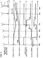
Fig. 2 , in the vertical direction thereof, there are shown the respective states of the moving speed of the welding torch TV, the feed speed of the welding wire WF, short circuit detect signal A/S, welding current I and welding voltage, whereas, in the horizontal axis thereof, there is shown time. As timings, TS0 designates a timing where a welding start signal is transmitted from therobot control unit 10 to the weldingpower supply device 5, while TS1 - TS5 respectively express timings following TS0. - In
Fig. 2 , according to the present embodiment, when the welding start signal is transmitted from therobot control unit 10 to the welding power supply device 5 (TS0), the weldingpower supply device 5 applies a no-load voltage V0 into between thewelding wire 1 and base metal 7 and also actuates thewire feed motor 3 to thereby accelerate thewelding wire 1 toward the base metal 7. - When the feed speed of the
welding wire 1 reaches an initial wire speed W0, the weldingpower supply device 5 causes thewire feed motor 3 to stop the acceleration of the welding wire but continues the wire feed at a constant speed. - Then, at the timing TS1, when the
welding wire 1 is contacted with the base metal 7, a short circuit signal A/S is output from short circuit detect means (not shown) which is provided in the inside of the weldingpower supply device 5. - The short circuit detect signal A/S is transmitted through the two-way communication S to the
robot control unit 10. Therobot control unit 10 immediately actuates therobot manipulator 9 to start to move thewelding torch 4 in a direction where thewelding torch 4 is pulled substantially apart from the base metal 7 and also to lift thewelding torch 4. - A period from
TS 1 to TS3 is a short circuit period and, during this period, thewelding wire 1 is continuously fed at an initial wire speed W0 and therobot manipulator 9 continues to lift thewelding torch 4. Therefore, the speed of the leading end portion of thewelding wire 1 is a composite speed of the wire speed WF and torch speed TV as shown by a broken line inFig. 2 . - Thus, the leading end of the
welding wire 1, at and after TS1, causes thewelding wire 1 to be pressed against the base metal until TS2 where the composite speed shown by a broken line inFig. 2 becomes zero; at and after TS2, the composite speed turns to a negative speed and thus the pressing amount decreases; and, at the timing TS3, the short circuit is opened. The timing TS3 occurs at the time when the wire lifting amount, that is, the area of a triangle hji exceeds the wire pressing amount or the area of a triangle fgh. - By the way, when an initial short circuit occurs at the timing TS1, the welding
power supply device 5 controls the welding current I to turn to I1 and, after passage of a given time, increases the current up to 12 and waits for the opening of the short circuit. - The reason why the welding current is controlled to I1 set relatively low as the first stage of the initial short circuit period is to prevent occurrence of a phenomenon that the wire can be molten due to the Joule heat of the wire leading end portion caused by the initial short circuit and thus the molten wire can spatter around simultaneously with generation of an arc.
- Also, the reason why the welding current is varied from 11 to 12 is to be able to provide sufficient energy to generate an arc when the short circuit is opened at the timing TS3.
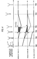
- Now,
Fig. 3 is an explanatory timing chart in which the wire speed WF according to the prior art shown by a broken line is overlapped on the same timing chart as shown inFig. 2 according to the present embodiment, in order to be able to compare the invention with the prior art. - As can be seen clearly from
Fig. 3 , in the arc start according to the prior art, at the time when the short circuit is opened and an arc is generated at the timing TS3, the welding wire starts to accelerate for the first time. Therefore, for example, if the timings of the invention and prior art when the wire speed becomes WF4 are compared with each other, the prior art method is found slower by the time from TS4 to TS4'.
As described above, according to the present embodiment, when it is detected that the leading end of thewelding wire 1 comes into contact with the base metal 7 used as the member to be welded, by lifting thewelding torch 4 using therobot manipulator 9 while continuing the forward feed of thewelding wire 1, an arc is generated in a state where thewelding wire 1 is separated from the base metal 7. Owing to this, not only the reverse operation of the robot manipulator is eliminated to thereby be able to reduce the waste time and thus the tact time but also an arc in the welding start end portion can be stabilized and thus the "unexpected stop" can be reduced effectively.
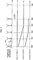
Next, description will be given below of an embodiment of an arc end according to the invention with reference to a timing chart shown inFig. 4 .
By the way, inFig. 4 , in the vertical direction thereof, there are shown the respective states of the moving speed of the welding torch TV, the feed speed of the welding wire WF and welding output P and, in the horizontal axis thereof, there is expressed time; and, as timings, the time when a welding end signal is transmitted from therobot control unit 10 to the weldingpower supply device 5 is expressed as a timing TE0, while TE1 - TE4 respectively express timings following the timing TE0.
According to the present embodiment, on receiving the welding end signal from therobot control unit 10, the weldingpower supply device 5 controls thewire feed motor 3 to reduce the speed of the welding wire.
In linking with the speed reduction of the welding wire, the welding output is also reduced and, at the timing TE1 where a predetermined condition is satisfied, the weldingpower supply device 5 transmits a start signal for lifting thewelding torch 4 to therobot control unit 10.
On receiving the lifting operation start signal from the weldingpower supply device 5, therobot control unit 10 immediately controls therobot manipulator 9 to lift thewelding torch 4.
As a result, the speed of the leading end of thewelding wire 1 becomes a composite speed of the wire speed WF and torch speed TV, that is, it becomes such speed as shown by a broken line inFig. 4 .
Thus, at the timing TE2, the speed of thewelding wire 1 becomes zero with respect to the base metal 7, thereby being able to stop the welding output P.
From that time on as well, the operation of thewelding wire 1 and the lifting operation of thewelding torch 4 are executed continuously but, at the time when the area of a trapezoid klmn, which corresponds to the lifting distance of thewelding torch 4, exceeds the area of a triangle opq corresponding to the inertial running distance of thewelding wire 1 until it stops, there is eliminated a danger of the wire stick phenomenon in which thewelding wire 1 is contacted with the molten pool of the base metal 7 and is thereby fixed. Therefore, therobot control unit 10 immediately controls therobot manipulator 9 so as to be able to switch over to a next operation (for example, an operation in which themanipulator 9 moves to the position of the welding torch at the welding start time for a next welding operation).
As described above, according to the present embodiment, since there is eliminated the time conventionally necessary for the "burn-back" operation, the tact time can be reduced quite effectively; and also, since there is prevented formation of a large ball-like fixed body in the leading end of thewelding wire 1 due to the burn-up of the welding wire, there can be avoided an ill influence on the welding start for the next step.
By the way, in the present embodiment, the lifting operation of the welding torch is carried out by the robot manipulator. However, there may also be provided an actuator separately and the lifting operation of the welding torch may be executed using this actuator. And, in this case, without using a robot, for example, using an automatic machine, the welding torch may be positioned or may be moved along a welding line, which, of course, has no ill influence on the effects of the invention. - A consumable electrode type welding method according to the invention not only can eliminate the need for the reverse operation of the robot manipulator to reduce the waste time to thereby be able to reduce the tact time but also can stabilize an arc in the welding start portion and reduce the "unexpected stop" effectively. Therefore, the invention is industrially useful as a consumable electrode type welding method which is used, for example, in production facilities and construction work.
-
-
Fig. 1 is a schematic block diagram of a welding system for use in an embodiment according to the invention. -
Fig. 2 is a timing chart for an arc start time in an embodiment according to the invention. -
Fig. 3 is a timing chart for an arc start time used to compare the embodiment according to the invention with a prior art technology. -
Fig. 4 is a timing chart for an arc end time in an embodiment according to the invention. -
Fig. 5 is a schematic block diagram of a welding system used in a prior art technology. -
Fig. 6 is a timing chart for an arc start time in a prior art technology. -
Fig. 7 is a timing chart for an arc end time in a prior art technology. -
- 1 : Welding wire
- 3: Wire feed motor
- 4: Welding torch
- 5: Welding power supply device
- 7: Base metal
- 8: Arc
- 9: Robot manipulator
- 10: Robot control unit
-
- 1. A consumable electrode type welding method in which, using a welding system comprising wire feed means for feeding a welding wire to a welding torch, an actuator for holding and moving the welding torch, a control unit for driving and controlling the actuator, and a welding power supply device for applying a welding output into between a member to be welded and the welding wire, the method comprising the steps of:
- moving the welding torch by the actuator in a direction parting away from the member to be welded while feeding the welding wire; and
- controlling the speed of the welding wire with respect to the member to be welded.
- 2. A consumable electrode type welding method as set forth in
Item 1, wherein, at a welding start time, firstly, the welding wire is fed while the actuator is stopped and, after the welding wire is contacted with the member to be welded, while applying a welding output, the welding torch is pulled apart from the member to be welded at a speed equal to or higher than the feed speed of the welding wire by the actuator. - 3. A consumable electrode type welding method as set forth in
item 2, wherein, at a welding start time, firstly, while the actuator is stopped, the speed for feeding the welding wire is set equal to or lower than the feed speed of the welding wire in a normal welding time and, after the welding torch is pulled apart from the member to be welded, the feed speed of the welding wire is changed to the feed speed of the welding wire in the above normal welding time. - 4. A consumable electrode type welding method as set forth in
Item - 5. A consumable electrode type welding method as set forth in
Item 1, wherein, in a welding end time, while reducing the feed speed of the welding wire as well as the welding output, the welding torch is pulled apart from the member to be welded at a speed equal to or higher than the feed speed of the welding wire by the actuator and, at a timing where the feed speed of the welding wire balances substantially with the moving speed of the actuator, the welding output is caused to stop. - 6. A consumable electrode type welding method as set forth in
Item 5, wherein, at least until the feed speed of the welding wire reaches zero, the welding torch is moved by the actuator in a direction where it is pulled apart from the member to be welded. - 7. A consumable electrode type welding method as set forth in
item
Claims (3)
- A consumable electrode type welding method in which, using a welding system comprising wire feed means (2, 3) for feeding a welding wire (1) to a welding torch (4), an actuator (9) for holding and moving the welding torch (4), a control unit (10) for driving and controlling the actuator (9), and a welding power supply device (5) for applying a welding output into between a member (7) to be welded and the welding wire (1), the method comprising the steps of:moving the welding torch (4) by the actuator in a direction parting away from the member (7) to be welded while feeding the welding wire (1); andcontrolling the speed of the welding wire (1) with respect to the member (7) to be welded,wherein, in a welding end time, while reducing the feed speed of the welding wire (1) as well as the welding output, the welding torch (4) is pulled apart from the member (7) to be welded at a speed equal to or higher than the feed speed of the welding wire (1) by the actuator (9) and, at a timing where the feed speed of the welding wire (1) balances substantially with the moving speed of the actuator (9), the welding output is caused to stop.
- A consumable electrode type welding method as set forth in Claim 1, wherein, at least until the feed speed of the welding wire (1) reaches zero, the welding torch (4) is moved by the actuator (9) in a direction where it is pulled apart from the member (7) to be welded.
- A consumable electrode type welding method as set forth in Claim 1 or 2, wherein, until the leading end position of the welding wire (1) reaches a distance between the welding wire (1) leading end and the member (7) to be welded in the welding start time, the welding torch (4) is pulled apart from the member (7) to be welded by the actuator (7).
Applications Claiming Priority (2)
| Application Number | Priority Date | Filing Date | Title |
|---|---|---|---|
| JP2004201526A JP3841091B2 (en) | 2004-07-08 | 2004-07-08 | Consumable electrode welding method |
| EP05753388.7A EP1676664B1 (en) | 2004-07-08 | 2005-06-27 | Consumable electrode type welding method |
Related Parent Applications (2)
| Application Number | Title | Priority Date | Filing Date |
|---|---|---|---|
| EP05753388.7A Division EP1676664B1 (en) | 2004-07-08 | 2005-06-27 | Consumable electrode type welding method |
| EP05753388.7 Division | 2005-06-27 |
Publications (3)
| Publication Number | Publication Date |
|---|---|
| EP2457680A2 true EP2457680A2 (en) | 2012-05-30 |
| EP2457680A3 EP2457680A3 (en) | 2016-09-07 |
| EP2457680B1 EP2457680B1 (en) | 2017-08-23 |
Family
ID=35783728
Family Applications (2)
| Application Number | Title | Priority Date | Filing Date |
|---|---|---|---|
| EP12000322.3A Active EP2457680B1 (en) | 2004-07-08 | 2005-06-27 | Consumable electrode type welding method |
| EP05753388.7A Active EP1676664B1 (en) | 2004-07-08 | 2005-06-27 | Consumable electrode type welding method |
Family Applications After (1)
| Application Number | Title | Priority Date | Filing Date |
|---|---|---|---|
| EP05753388.7A Active EP1676664B1 (en) | 2004-07-08 | 2005-06-27 | Consumable electrode type welding method |
Country Status (5)
| Country | Link |
|---|---|
| US (1) | US7525066B2 (en) |
| EP (2) | EP2457680B1 (en) |
| JP (1) | JP3841091B2 (en) |
| CN (1) | CN100462176C (en) |
| WO (1) | WO2006006383A1 (en) |
Families Citing this family (13)
| Publication number | Priority date | Publication date | Assignee | Title |
|---|---|---|---|---|
| JP4698977B2 (en) * | 2004-07-12 | 2011-06-08 | 株式会社ダイヘン | Welding robot control system |
| JP4875393B2 (en) * | 2005-10-27 | 2012-02-15 | 株式会社ダイヘン | Arc start control method for two-electrode arc welding |
| JP2006263820A (en) * | 2006-05-16 | 2006-10-05 | Matsushita Electric Ind Co Ltd | Consumable electrode welding method |
| JP5005332B2 (en) * | 2006-12-20 | 2012-08-22 | 株式会社ダイヘン | Arc start control method for consumable electrode arc welding |
| DE102007015835A1 (en) * | 2007-03-30 | 2008-10-02 | Ewm Hightec Welding Gmbh | Method for manually igniting a soldering or welding arc |
| EP2269758B1 (en) | 2009-07-03 | 2017-05-17 | Ewm Ag | DC arc welding method |
| CN102264500B (en) | 2009-07-10 | 2013-07-10 | 松下电器产业株式会社 | Arc welding control method and arc welding device |
| JP5141826B2 (en) * | 2009-08-28 | 2013-02-13 | パナソニック株式会社 | Arc welding method and arc welding apparatus |
| JP5170321B2 (en) * | 2009-11-25 | 2013-03-27 | パナソニック株式会社 | Welding method and welding apparatus |
| JP4745453B1 (en) * | 2010-09-30 | 2011-08-10 | 株式会社ダイヘン | Arc welding equipment |
| US8993926B2 (en) * | 2010-10-07 | 2015-03-31 | Panasonic Intellectual Property Management Co., Ltd. | Method for arc welding |
| EP3342521B1 (en) * | 2012-03-16 | 2019-08-21 | Panasonic Intellectual Property Management Co., Ltd. | Arc welding device |
| JP6599505B2 (en) * | 2018-04-27 | 2019-10-30 | 株式会社ダイヘン | Arc end adjusting device, welding system, arc end adjusting method, and computer program |
Family Cites Families (15)
| Publication number | Priority date | Publication date | Assignee | Title |
|---|---|---|---|---|
| JPS58181479A (en) * | 1982-04-20 | 1983-10-24 | Toshiba Corp | Welding robot |
| JPS60221175A (en) * | 1984-03-22 | 1985-11-05 | Mitsubishi Electric Corp | Method and device for consumable electrode type arc welding |
| JPS61147972A (en) * | 1984-12-19 | 1986-07-05 | Matsushita Electric Ind Co Ltd | Power source for consumable electrode type welding |
| CN2254800Y (en) * | 1996-03-25 | 1997-05-28 | 尹洪珠 | Device for automatically feeding electrode for arc welding machine |
| JPH1158012A (en) * | 1997-08-25 | 1999-03-02 | Daihen Corp | Wire extension detection method |
| JPH11347732A (en) * | 1998-06-05 | 1999-12-21 | Yaskawa Electric Corp | Weld starting spot control method for welding robot |
| JP4029476B2 (en) * | 1998-06-17 | 2008-01-09 | 松下電器産業株式会社 | Welding end control method and arc welding machine |
| JP4940449B2 (en) * | 1999-03-18 | 2012-05-30 | 株式会社安川電機 | Consumable electrode arc welding method and apparatus |
| JP4045713B2 (en) * | 2000-01-31 | 2008-02-13 | 松下電器産業株式会社 | Welding machine for automatic machine |
| AT411878B (en) * | 2000-10-17 | 2004-07-26 | Fronius Schweissmasch Prod | METHOD FOR CONTROLLING AND / OR REGULATING A WELDING PROCESS |
| CA2395912C (en) * | 2000-12-07 | 2009-01-20 | Honda Giken Kogyo Kabushiki Kaisha | Control method for arc welding process and arc welding apparatus |
| JP2002178146A (en) * | 2000-12-15 | 2002-06-25 | Daihen Corp | Arc start control method |
| JP4499303B2 (en) | 2001-01-09 | 2010-07-07 | 株式会社ダイヘン | Arc start control method for robot arc welding |
| JP3990182B2 (en) * | 2002-04-19 | 2007-10-10 | 株式会社ダイヘン | Arc start control method |
| CN1186161C (en) * | 2002-06-27 | 2005-01-26 | 上海交通大学 | Arc stricking method for metal gas arc welding |
-
2004
- 2004-07-08 JP JP2004201526A patent/JP3841091B2/en active Active
-
2005
- 2005-06-27 CN CNB2005800007211A patent/CN100462176C/en active Active
- 2005-06-27 WO PCT/JP2005/011767 patent/WO2006006383A1/en not_active Application Discontinuation
- 2005-06-27 EP EP12000322.3A patent/EP2457680B1/en active Active
- 2005-06-27 EP EP05753388.7A patent/EP1676664B1/en active Active
- 2005-06-27 US US10/568,552 patent/US7525066B2/en active Active
Non-Patent Citations (1)
| Title |
|---|
| None |
Also Published As
| Publication number | Publication date |
|---|---|
| EP1676664A4 (en) | 2009-05-06 |
| EP2457680A3 (en) | 2016-09-07 |
| JP3841091B2 (en) | 2006-11-01 |
| EP2457680B1 (en) | 2017-08-23 |
| CN1839009A (en) | 2006-09-27 |
| EP1676664A1 (en) | 2006-07-05 |
| EP1676664B1 (en) | 2013-10-23 |
| WO2006006383A1 (en) | 2006-01-19 |
| US20080169276A1 (en) | 2008-07-17 |
| US7525066B2 (en) | 2009-04-28 |
| CN100462176C (en) | 2009-02-18 |
| JP2006021228A (en) | 2006-01-26 |
Similar Documents
| Publication | Publication Date | Title |
|---|---|---|
| EP1676664B1 (en) | Consumable electrode type welding method | |
| JP4807479B2 (en) | Arc welding control method and arc welding apparatus | |
| JP4844564B2 (en) | Arc welding control method | |
| JP2012066288A (en) | Arc welding method reducing occurrence of spatter at time of arc start | |
| JP2007030018A (en) | Arc start control method for robot welding | |
| JPWO2009051107A1 (en) | Arc start control method | |
| US9962786B2 (en) | Arc welding method, arc welding apparatus, and arc welding controller | |
| JP4058099B2 (en) | Two-electrode arc welding end method | |
| CN113226615B (en) | Method for controlling a welding process with a consumable electrode and welding device having such a control device | |
| JP4780173B2 (en) | Consumable electrode welding method | |
| JP2002205169A (en) | Method for controlling start of arc in arc welding with robot | |
| JP4548387B2 (en) | Consumable electrode welding method | |
| JP6019380B2 (en) | Arc welding control method and arc welding apparatus | |
| JP7309671B2 (en) | Welding power source, welding system, control method and program for welding power source | |
| JP2006263820A (en) | Consumable electrode welding method | |
| JP4864233B2 (en) | Consumable two-electrode arc welding end method, welding end control method, and welding robot | |
| JP4175316B2 (en) | Welding system and method for controlling welding robot | |
| JP2586128B2 (en) | Automatic arc welding method using robot | |
| JP2008126233A (en) | Start synchronized arc welding method | |
| JPS62166077A (en) | Welding wire feeding method in arc welding | |
| JP2004042121A (en) | Consumable electrode type gas shielded arc welding method | |
| JP6330144B2 (en) | Welding system | |
| JP2001001143A (en) | Arc welding method with consumable electrode | |
| JP2005279739A (en) | Welding apparatus | |
| JPS63199078A (en) | Tig welding method |
Legal Events
| Date | Code | Title | Description |
|---|---|---|---|
| PUAI | Public reference made under article 153(3) epc to a published international application that has entered the european phase |
Free format text: ORIGINAL CODE: 0009012 |
|
| 17P | Request for examination filed |
Effective date: 20120119 |
|
| AC | Divisional application: reference to earlier application |
Ref document number: 1676664 Country of ref document: EP Kind code of ref document: P |
|
| AK | Designated contracting states |
Kind code of ref document: A2 Designated state(s): AT BE BG CH CY CZ DE DK EE ES FI FR GB GR HU IE IS IT LI LT LU MC NL PL PT RO SE SI SK TR |
|
| RAP1 | Party data changed (applicant data changed or rights of an application transferred) |
Owner name: PANASONIC INTELLECTUAL PROPERTY MANAGEMENT CO., LT |
|
| RAP1 | Party data changed (applicant data changed or rights of an application transferred) |
Owner name: PANASONIC INTELLECTUAL PROPERTY MANAGEMENT CO., LT |
|
| PUAL | Search report despatched |
Free format text: ORIGINAL CODE: 0009013 |
|
| AK | Designated contracting states |
Kind code of ref document: A3 Designated state(s): AT BE BG CH CY CZ DE DK EE ES FI FR GB GR HU IE IS IT LI LT LU MC NL PL PT RO SE SI SK TR |
|
| RIC1 | Information provided on ipc code assigned before grant |
Ipc: B23K 9/173 20060101ALI20160729BHEP Ipc: B23K 9/12 20060101AFI20160729BHEP |
|
| RBV | Designated contracting states (corrected) |
Designated state(s): AT BE BG CH CY CZ DE DK EE ES FI FR GB GR HU IE IS IT LI LT LU MC NL PL PT RO SE SI SK TR |
|
| GRAP | Despatch of communication of intention to grant a patent |
Free format text: ORIGINAL CODE: EPIDOSNIGR1 |
|
| STAA | Information on the status of an ep patent application or granted ep patent |
Free format text: STATUS: GRANT OF PATENT IS INTENDED |
|
| RIC1 | Information provided on ipc code assigned before grant |
Ipc: B23K 9/12 20060101AFI20170214BHEP Ipc: B23K 9/173 20060101ALI20170214BHEP |
|
| INTG | Intention to grant announced |
Effective date: 20170316 |
|
| GRAS | Grant fee paid |
Free format text: ORIGINAL CODE: EPIDOSNIGR3 |
|
| GRAA | (expected) grant |
Free format text: ORIGINAL CODE: 0009210 |
|
| STAA | Information on the status of an ep patent application or granted ep patent |
Free format text: STATUS: THE PATENT HAS BEEN GRANTED |
|
| AC | Divisional application: reference to earlier application |
Ref document number: 1676664 Country of ref document: EP Kind code of ref document: P |
|
| AK | Designated contracting states |
Kind code of ref document: B1 Designated state(s): AT BE BG CH CY CZ DE DK EE ES FI FR GB GR HU IE IS IT LI LT LU MC NL PL PT RO SE SI SK TR |
|
| REG | Reference to a national code |
Ref country code: GB Ref legal event code: FG4D |
|
| REG | Reference to a national code |
Ref country code: CH Ref legal event code: EP |
|
| REG | Reference to a national code |
Ref country code: AT Ref legal event code: REF Ref document number: 920808 Country of ref document: AT Kind code of ref document: T Effective date: 20170915 |
|
| REG | Reference to a national code |
Ref country code: IE Ref legal event code: FG4D |
|
| REG | Reference to a national code |
Ref country code: DE Ref legal event code: R096 Ref document number: 602005052607 Country of ref document: DE |
|
| REG | Reference to a national code |
Ref country code: NL Ref legal event code: FP |
|
| REG | Reference to a national code |
Ref country code: LT Ref legal event code: MG4D |
|
| REG | Reference to a national code |
Ref country code: AT Ref legal event code: MK05 Ref document number: 920808 Country of ref document: AT Kind code of ref document: T Effective date: 20170823 |
|
| PG25 | Lapsed in a contracting state [announced via postgrant information from national office to epo] |
Ref country code: AT Free format text: LAPSE BECAUSE OF FAILURE TO SUBMIT A TRANSLATION OF THE DESCRIPTION OR TO PAY THE FEE WITHIN THE PRESCRIBED TIME-LIMIT Effective date: 20170823 Ref country code: FI Free format text: LAPSE BECAUSE OF FAILURE TO SUBMIT A TRANSLATION OF THE DESCRIPTION OR TO PAY THE FEE WITHIN THE PRESCRIBED TIME-LIMIT Effective date: 20170823 Ref country code: SE Free format text: LAPSE BECAUSE OF FAILURE TO SUBMIT A TRANSLATION OF THE DESCRIPTION OR TO PAY THE FEE WITHIN THE PRESCRIBED TIME-LIMIT Effective date: 20170823 Ref country code: LT Free format text: LAPSE BECAUSE OF FAILURE TO SUBMIT A TRANSLATION OF THE DESCRIPTION OR TO PAY THE FEE WITHIN THE PRESCRIBED TIME-LIMIT Effective date: 20170823 |
|
| PG25 | Lapsed in a contracting state [announced via postgrant information from national office to epo] |
Ref country code: BG Free format text: LAPSE BECAUSE OF FAILURE TO SUBMIT A TRANSLATION OF THE DESCRIPTION OR TO PAY THE FEE WITHIN THE PRESCRIBED TIME-LIMIT Effective date: 20171123 Ref country code: PL Free format text: LAPSE BECAUSE OF FAILURE TO SUBMIT A TRANSLATION OF THE DESCRIPTION OR TO PAY THE FEE WITHIN THE PRESCRIBED TIME-LIMIT Effective date: 20170823 Ref country code: GR Free format text: LAPSE BECAUSE OF FAILURE TO SUBMIT A TRANSLATION OF THE DESCRIPTION OR TO PAY THE FEE WITHIN THE PRESCRIBED TIME-LIMIT Effective date: 20171124 Ref country code: IS Free format text: LAPSE BECAUSE OF FAILURE TO SUBMIT A TRANSLATION OF THE DESCRIPTION OR TO PAY THE FEE WITHIN THE PRESCRIBED TIME-LIMIT Effective date: 20171223 Ref country code: ES Free format text: LAPSE BECAUSE OF FAILURE TO SUBMIT A TRANSLATION OF THE DESCRIPTION OR TO PAY THE FEE WITHIN THE PRESCRIBED TIME-LIMIT Effective date: 20170823 |
|
| PG25 | Lapsed in a contracting state [announced via postgrant information from national office to epo] |
Ref country code: RO Free format text: LAPSE BECAUSE OF FAILURE TO SUBMIT A TRANSLATION OF THE DESCRIPTION OR TO PAY THE FEE WITHIN THE PRESCRIBED TIME-LIMIT Effective date: 20170823 Ref country code: CZ Free format text: LAPSE BECAUSE OF FAILURE TO SUBMIT A TRANSLATION OF THE DESCRIPTION OR TO PAY THE FEE WITHIN THE PRESCRIBED TIME-LIMIT Effective date: 20170823 Ref country code: DK Free format text: LAPSE BECAUSE OF FAILURE TO SUBMIT A TRANSLATION OF THE DESCRIPTION OR TO PAY THE FEE WITHIN THE PRESCRIBED TIME-LIMIT Effective date: 20170823 |
|
| REG | Reference to a national code |
Ref country code: DE Ref legal event code: R097 Ref document number: 602005052607 Country of ref document: DE |
|
| PG25 | Lapsed in a contracting state [announced via postgrant information from national office to epo] |
Ref country code: SK Free format text: LAPSE BECAUSE OF FAILURE TO SUBMIT A TRANSLATION OF THE DESCRIPTION OR TO PAY THE FEE WITHIN THE PRESCRIBED TIME-LIMIT Effective date: 20170823 Ref country code: EE Free format text: LAPSE BECAUSE OF FAILURE TO SUBMIT A TRANSLATION OF THE DESCRIPTION OR TO PAY THE FEE WITHIN THE PRESCRIBED TIME-LIMIT Effective date: 20170823 |
|
| PLBE | No opposition filed within time limit |
Free format text: ORIGINAL CODE: 0009261 |
|
| STAA | Information on the status of an ep patent application or granted ep patent |
Free format text: STATUS: NO OPPOSITION FILED WITHIN TIME LIMIT |
|
| 26N | No opposition filed |
Effective date: 20180524 |
|
| PG25 | Lapsed in a contracting state [announced via postgrant information from national office to epo] |
Ref country code: SI Free format text: LAPSE BECAUSE OF FAILURE TO SUBMIT A TRANSLATION OF THE DESCRIPTION OR TO PAY THE FEE WITHIN THE PRESCRIBED TIME-LIMIT Effective date: 20170823 |
|
| REG | Reference to a national code |
Ref country code: CH Ref legal event code: PL |
|
| GBPC | Gb: european patent ceased through non-payment of renewal fee |
Effective date: 20180627 |
|
| REG | Reference to a national code |
Ref country code: BE Ref legal event code: MM Effective date: 20180630 |
|
| PG25 | Lapsed in a contracting state [announced via postgrant information from national office to epo] |
Ref country code: LU Free format text: LAPSE BECAUSE OF NON-PAYMENT OF DUE FEES Effective date: 20180627 Ref country code: MC Free format text: LAPSE BECAUSE OF FAILURE TO SUBMIT A TRANSLATION OF THE DESCRIPTION OR TO PAY THE FEE WITHIN THE PRESCRIBED TIME-LIMIT Effective date: 20170823 |
|
| REG | Reference to a national code |
Ref country code: IE Ref legal event code: MM4A |
|
| PG25 | Lapsed in a contracting state [announced via postgrant information from national office to epo] |
Ref country code: GB Free format text: LAPSE BECAUSE OF NON-PAYMENT OF DUE FEES Effective date: 20180627 Ref country code: IE Free format text: LAPSE BECAUSE OF NON-PAYMENT OF DUE FEES Effective date: 20180627 Ref country code: FR Free format text: LAPSE BECAUSE OF NON-PAYMENT OF DUE FEES Effective date: 20180630 Ref country code: LI Free format text: LAPSE BECAUSE OF NON-PAYMENT OF DUE FEES Effective date: 20180630 Ref country code: CH Free format text: LAPSE BECAUSE OF NON-PAYMENT OF DUE FEES Effective date: 20180630 |
|
| PG25 | Lapsed in a contracting state [announced via postgrant information from national office to epo] |
Ref country code: BE Free format text: LAPSE BECAUSE OF NON-PAYMENT OF DUE FEES Effective date: 20180630 |
|
| PG25 | Lapsed in a contracting state [announced via postgrant information from national office to epo] |
Ref country code: TR Free format text: LAPSE BECAUSE OF FAILURE TO SUBMIT A TRANSLATION OF THE DESCRIPTION OR TO PAY THE FEE WITHIN THE PRESCRIBED TIME-LIMIT Effective date: 20170823 |
|
| PG25 | Lapsed in a contracting state [announced via postgrant information from national office to epo] |
Ref country code: PT Free format text: LAPSE BECAUSE OF FAILURE TO SUBMIT A TRANSLATION OF THE DESCRIPTION OR TO PAY THE FEE WITHIN THE PRESCRIBED TIME-LIMIT Effective date: 20170823 Ref country code: HU Free format text: LAPSE BECAUSE OF FAILURE TO SUBMIT A TRANSLATION OF THE DESCRIPTION OR TO PAY THE FEE WITHIN THE PRESCRIBED TIME-LIMIT; INVALID AB INITIO Effective date: 20050627 |
|
| PG25 | Lapsed in a contracting state [announced via postgrant information from national office to epo] |
Ref country code: CY Free format text: LAPSE BECAUSE OF FAILURE TO SUBMIT A TRANSLATION OF THE DESCRIPTION OR TO PAY THE FEE WITHIN THE PRESCRIBED TIME-LIMIT Effective date: 20170823 |
|
| PGFP | Annual fee paid to national office [announced via postgrant information from national office to epo] |
Ref country code: NL Payment date: 20200625 Year of fee payment: 16 |
|
| PGFP | Annual fee paid to national office [announced via postgrant information from national office to epo] |
Ref country code: IT Payment date: 20200625 Year of fee payment: 16 |
|
| REG | Reference to a national code |
Ref country code: NL Ref legal event code: MM Effective date: 20210701 |
|
| PG25 | Lapsed in a contracting state [announced via postgrant information from national office to epo] |
Ref country code: NL Free format text: LAPSE BECAUSE OF NON-PAYMENT OF DUE FEES Effective date: 20210701 |
|
| PG25 | Lapsed in a contracting state [announced via postgrant information from national office to epo] |
Ref country code: IT Free format text: LAPSE BECAUSE OF NON-PAYMENT OF DUE FEES Effective date: 20210627 |
|
| PGFP | Annual fee paid to national office [announced via postgrant information from national office to epo] |
Ref country code: DE Payment date: 20230620 Year of fee payment: 19 |