EP2457669A2 - A storage chamber cover and a cloth bonding apparatus - Google Patents
A storage chamber cover and a cloth bonding apparatus Download PDFInfo
- Publication number
- EP2457669A2 EP2457669A2 EP11187562A EP11187562A EP2457669A2 EP 2457669 A2 EP2457669 A2 EP 2457669A2 EP 11187562 A EP11187562 A EP 11187562A EP 11187562 A EP11187562 A EP 11187562A EP 2457669 A2 EP2457669 A2 EP 2457669A2
- Authority
- EP
- European Patent Office
- Prior art keywords
- storage chamber
- cover
- screw
- chamber cover
- fixing
- Prior art date
- Legal status (The legal status is an assumption and is not a legal conclusion. Google has not performed a legal analysis and makes no representation as to the accuracy of the status listed.)
- Granted
Links
- 239000004744 fabric Substances 0.000 title claims abstract description 24
- 239000000853 adhesive Substances 0.000 claims abstract description 24
- 230000001070 adhesive effect Effects 0.000 claims abstract description 24
- 238000010438 heat treatment Methods 0.000 claims description 5
- 239000000155 melt Substances 0.000 claims description 4
- 230000000903 blocking effect Effects 0.000 description 5
- 238000003780 insertion Methods 0.000 description 5
- 230000037431 insertion Effects 0.000 description 5
- 239000002184 metal Substances 0.000 description 3
- 238000012856 packing Methods 0.000 description 3
- 238000001035 drying Methods 0.000 description 1
- 230000000694 effects Effects 0.000 description 1
- 230000005611 electricity Effects 0.000 description 1
- 238000012986 modification Methods 0.000 description 1
- 230000004048 modification Effects 0.000 description 1
- 238000009958 sewing Methods 0.000 description 1
- 229920003002 synthetic resin Polymers 0.000 description 1
- 239000000057 synthetic resin Substances 0.000 description 1
Images



Classifications
-
- B—PERFORMING OPERATIONS; TRANSPORTING
- B05—SPRAYING OR ATOMISING IN GENERAL; APPLYING FLUENT MATERIALS TO SURFACES, IN GENERAL
- B05C—APPARATUS FOR APPLYING FLUENT MATERIALS TO SURFACES, IN GENERAL
- B05C5/00—Apparatus in which liquid or other fluent material is projected, poured or allowed to flow on to the surface of the work
- B05C5/02—Apparatus in which liquid or other fluent material is projected, poured or allowed to flow on to the surface of the work the liquid or other fluent material being discharged through an outlet orifice by pressure, e.g. from an outlet device in contact or almost in contact, with the work
- B05C5/0208—Apparatus in which liquid or other fluent material is projected, poured or allowed to flow on to the surface of the work the liquid or other fluent material being discharged through an outlet orifice by pressure, e.g. from an outlet device in contact or almost in contact, with the work for applying liquid or other fluent material to separate articles
-
- B—PERFORMING OPERATIONS; TRANSPORTING
- B29—WORKING OF PLASTICS; WORKING OF SUBSTANCES IN A PLASTIC STATE IN GENERAL
- B29C—SHAPING OR JOINING OF PLASTICS; SHAPING OF MATERIAL IN A PLASTIC STATE, NOT OTHERWISE PROVIDED FOR; AFTER-TREATMENT OF THE SHAPED PRODUCTS, e.g. REPAIRING
- B29C65/00—Joining or sealing of preformed parts, e.g. welding of plastics materials; Apparatus therefor
- B29C65/48—Joining or sealing of preformed parts, e.g. welding of plastics materials; Apparatus therefor using adhesives, i.e. using supplementary joining material; solvent bonding
- B29C65/4805—Joining or sealing of preformed parts, e.g. welding of plastics materials; Apparatus therefor using adhesives, i.e. using supplementary joining material; solvent bonding characterised by the type of adhesives
- B29C65/481—Non-reactive adhesives, e.g. physically hardening adhesives
- B29C65/4815—Hot melt adhesives, e.g. thermoplastic adhesives
-
- B—PERFORMING OPERATIONS; TRANSPORTING
- B29—WORKING OF PLASTICS; WORKING OF SUBSTANCES IN A PLASTIC STATE IN GENERAL
- B29C—SHAPING OR JOINING OF PLASTICS; SHAPING OF MATERIAL IN A PLASTIC STATE, NOT OTHERWISE PROVIDED FOR; AFTER-TREATMENT OF THE SHAPED PRODUCTS, e.g. REPAIRING
- B29C65/00—Joining or sealing of preformed parts, e.g. welding of plastics materials; Apparatus therefor
- B29C65/48—Joining or sealing of preformed parts, e.g. welding of plastics materials; Apparatus therefor using adhesives, i.e. using supplementary joining material; solvent bonding
- B29C65/52—Joining or sealing of preformed parts, e.g. welding of plastics materials; Apparatus therefor using adhesives, i.e. using supplementary joining material; solvent bonding characterised by the way of applying the adhesive
- B29C65/524—Joining or sealing of preformed parts, e.g. welding of plastics materials; Apparatus therefor using adhesives, i.e. using supplementary joining material; solvent bonding characterised by the way of applying the adhesive by applying the adhesive from an outlet device in contact with, or almost in contact with, the surface of the part to be joined
-
- B—PERFORMING OPERATIONS; TRANSPORTING
- B29—WORKING OF PLASTICS; WORKING OF SUBSTANCES IN A PLASTIC STATE IN GENERAL
- B29C—SHAPING OR JOINING OF PLASTICS; SHAPING OF MATERIAL IN A PLASTIC STATE, NOT OTHERWISE PROVIDED FOR; AFTER-TREATMENT OF THE SHAPED PRODUCTS, e.g. REPAIRING
- B29C66/00—General aspects of processes or apparatus for joining preformed parts
- B29C66/40—General aspects of joining substantially flat articles, e.g. plates, sheets or web-like materials; Making flat seams in tubular or hollow articles; Joining single elements to substantially flat surfaces
- B29C66/41—Joining substantially flat articles ; Making flat seams in tubular or hollow articles
- B29C66/43—Joining a relatively small portion of the surface of said articles
-
- B—PERFORMING OPERATIONS; TRANSPORTING
- B29—WORKING OF PLASTICS; WORKING OF SUBSTANCES IN A PLASTIC STATE IN GENERAL
- B29C—SHAPING OR JOINING OF PLASTICS; SHAPING OF MATERIAL IN A PLASTIC STATE, NOT OTHERWISE PROVIDED FOR; AFTER-TREATMENT OF THE SHAPED PRODUCTS, e.g. REPAIRING
- B29C66/00—General aspects of processes or apparatus for joining preformed parts
- B29C66/80—General aspects of machine operations or constructions and parts thereof
- B29C66/81—General aspects of the pressing elements, i.e. the elements applying pressure on the parts to be joined in the area to be joined, e.g. the welding jaws or clamps
- B29C66/816—General aspects of the pressing elements, i.e. the elements applying pressure on the parts to be joined in the area to be joined, e.g. the welding jaws or clamps characterised by the mounting of the pressing elements, e.g. of the welding jaws or clamps
- B29C66/8161—General aspects of the pressing elements, i.e. the elements applying pressure on the parts to be joined in the area to be joined, e.g. the welding jaws or clamps characterised by the mounting of the pressing elements, e.g. of the welding jaws or clamps said pressing elements being supported or backed-up by springs or by resilient material
-
- B—PERFORMING OPERATIONS; TRANSPORTING
- B29—WORKING OF PLASTICS; WORKING OF SUBSTANCES IN A PLASTIC STATE IN GENERAL
- B29C—SHAPING OR JOINING OF PLASTICS; SHAPING OF MATERIAL IN A PLASTIC STATE, NOT OTHERWISE PROVIDED FOR; AFTER-TREATMENT OF THE SHAPED PRODUCTS, e.g. REPAIRING
- B29C66/00—General aspects of processes or apparatus for joining preformed parts
- B29C66/80—General aspects of machine operations or constructions and parts thereof
- B29C66/81—General aspects of the pressing elements, i.e. the elements applying pressure on the parts to be joined in the area to be joined, e.g. the welding jaws or clamps
- B29C66/816—General aspects of the pressing elements, i.e. the elements applying pressure on the parts to be joined in the area to be joined, e.g. the welding jaws or clamps characterised by the mounting of the pressing elements, e.g. of the welding jaws or clamps
- B29C66/8167—Quick change joining tools or surfaces
-
- B—PERFORMING OPERATIONS; TRANSPORTING
- B29—WORKING OF PLASTICS; WORKING OF SUBSTANCES IN A PLASTIC STATE IN GENERAL
- B29C—SHAPING OR JOINING OF PLASTICS; SHAPING OF MATERIAL IN A PLASTIC STATE, NOT OTHERWISE PROVIDED FOR; AFTER-TREATMENT OF THE SHAPED PRODUCTS, e.g. REPAIRING
- B29C66/00—General aspects of processes or apparatus for joining preformed parts
- B29C66/80—General aspects of machine operations or constructions and parts thereof
- B29C66/83—General aspects of machine operations or constructions and parts thereof characterised by the movement of the joining or pressing tools
- B29C66/834—General aspects of machine operations or constructions and parts thereof characterised by the movement of the joining or pressing tools moving with the parts to be joined
- B29C66/8341—Roller, cylinder or drum types; Band or belt types; Ball types
- B29C66/83431—Roller, cylinder or drum types; Band or belt types; Ball types rollers, cylinders or drums cooperating with bands or belts
-
- B—PERFORMING OPERATIONS; TRANSPORTING
- B29—WORKING OF PLASTICS; WORKING OF SUBSTANCES IN A PLASTIC STATE IN GENERAL
- B29C—SHAPING OR JOINING OF PLASTICS; SHAPING OF MATERIAL IN A PLASTIC STATE, NOT OTHERWISE PROVIDED FOR; AFTER-TREATMENT OF THE SHAPED PRODUCTS, e.g. REPAIRING
- B29C66/00—General aspects of processes or apparatus for joining preformed parts
- B29C66/80—General aspects of machine operations or constructions and parts thereof
- B29C66/84—Specific machine types or machines suitable for specific applications
- B29C66/845—C-clamp type or sewing machine type
Definitions
- the present invention relates to a storage chamber cover that is mounted on a storage chamber for an adhesive and to a cloth bonding apparatus that is provided with the storage chamber cover.
- a cloth bonding apparatus bonds a cloth to a cloth with an adhesive instead of sewing the cloths together with a needle and a thread.
- the cloth bonding apparatus is provided with a storage chamber and a nozzle.
- the storage chamber stores the adhesive and melts the stored adhesive by heating it.
- the nozzle discharges the adhesive that is melted in the storage chamber and applies the adhesive between the two cloths.
- the cloth bonding apparatus bonds the two cloths by pressing them together. Because the bonded cloths have not been sewn together with the thread, there is no unevenness in the bonded cloths.
- the structures of the cloth bonding apparatus and the storage chamber are disclosed in the Japanese Laid-Open Patent Publication No. 2010-222764 .
- the cloth bonding apparatus raises the air pressure within the storage chamber, extruding the adhesive and supplying it to the nozzle.
- the interior portion of the storage chamber must therefore be sealed.
- the sealed storage chamber prevents drying of the adhesive.
- the storage chamber has a shaft bearing at its upper end, and a cover portion has a shaft portion. The cover portion turns around the shaft portion.
- the storage chamber has an opening portion in its upper portion, and the cover portion covers the opening portion.
- the opening portion in the upper portion of the storage chamber is only covered by the plate-shaped cover portion. Therefore, the possibility exists that the interior portion of the storage chamber cannot be reliably sealed.
- the temperature of the storage chamber is raised to high, so an operator must wear heat-resistant gloves when the operator opens and closes the plate-shaped cover portion.
- the heat-resistant gloves are slippery. Therefore, it is difficult for the operator to open and close the cover portion while wearing the heat-resistant gloves.
- the present invention provides a storage chamber cover that reliably seals the storage chamber and that can be mounted and removed easily and safely, and a cloth bonding apparatus that is provided with the storage chamber cover.
- a storage chamber cover that is mounted on a storage chamber that stores an adhesive inside and that melts the stored adhesive by heating, includes a tube portion that has a tube shape and that covers an outer circumference of the storage chamber; a top wall that is formed on one of two openings in the tube portion; and a cover fixing portion that fixes, on an inner side of the tube portion, a screw cover that is mounted by being screwed onto an opening portion of the storage chamber, in a state in which an axis of rotation of the screw cover and a central axis of the tube portion are parallel to one another, wherein at least one recessed portion that is recessed toward the inside is formed in the tube portion.
- the storage chamber cover By rotating the storage chamber cover, an operator can firmly fix the screw cover, which has been mounted to the inner side of the storage chamber cover, on the opening portion of the storage chamber. Therefore, the operator can reliably seal off the interior portion of the storage chamber. Because the storage chamber cover is positioned on the outside of the screw cover, the temperature of the storage chamber cover is lower than the temperature of the screw cover when the temperature of the storage chamber is high. Therefore, the operator can fix and remove the screw cover more safely than when the operator rotates the screw cover by touching the screw cover directly.
- the tube portion of the storage chamber cover has the recessed portion that is recessed toward the inside. The operator can rotate the storage chamber cover by placing his fingers on the recessed portion, so his hand tends not to slip, even when he is wearing the heat-resistant gloves. Therefore, the operator can easily and safely perform the fixing and the removing of the screw cover.
- the storage chamber cover may be provided with a vent hole formed on at least one of the tube portion and the top wall.
- the storage chamber cover can discharge heat from the inside to the outside through the vent hole.
- the temperature of the storage chamber cover is lower than when the vent hole is not formed. Therefore, the operator can perform work safely.
- the storage chamber cover may be mounted on an upper portion of the storage chamber such that the top wall covers the top of the storage chamber.
- the vent hole may be formed in the top wall side in the recessed portion. Air that has reached a high temperature rises in the storage chamber cover and escapes through the vent hole in the upper portion of recessed portion. Therefore, the vent hole can efficiently inhibit any rise in the temperature of the storage chamber cover. Dirt is less likely to enter the interior of the storage chamber cover from the vent hole than in the case the vent hole is formed in the top wall.
- the forming of the vent hole in the recessed portion makes it easier for the operator's hand to get a hold in the recessed portion. Therefore, the operator can perform work more easily and safely.
- the storage chamber cover may be provided with a projecting portion that is formed on an upper edge portion of the recessed portion to project in a direction away from the central axis of the tube portion.
- the cover fixing portion may be provided with a fixing screw that is screwed into a screw hole formed in the screw cover and with a rotation preventing portion that fits together with one of a fixing concave portion and a fixing projecting portion formed in the screw cover.
- the storage chamber cover can firmly fix the screw cover with the fixing screw.
- the screw cover can be prevented from rotating in relation to the storage chamber cover by engaging the rotation preventing portion with the one of the fixing concave portion and the fixing projecting portion of the screw cover. Therefore, the screw cover can be fixed more reliably than when the screw cover is fixed to the storage chamber cover only by the fixing screw. If the operator tightens the fixing screw after engaging the rotation preventing portion with the one of the fixing concave portion and the fixing projecting portion of the screw cover, the screw cover can easily be fixed to the storage chamber cover at the proper angle.
- a cloth bonding apparatus in a second aspect of this invention, includes the storage chamber cover, the storage chamber, and the screw cover described above, wherein cloths are bonded with an adhesive that is stored in the storage chamber. Therefore, the cloth bonding apparatus provides the same effects as the storage chamber cover. By using the cloth bonding apparatus, the operator can perform the work of bonding the cloths safely and easily.
- the configuration of the cloth bonding apparatus 1 will be explained with reference to FIG. 1 .
- the lower right side, the upper left side, the upper right side, and the lower left side of the FIG. 1 respectively correspond to the front side, the rear side, the right side and the left side of the cloth bonding apparatus 1.
- the cloth bonding apparatus 1 is provided with a bed portion 2, a pillar portion 3, and an arm portion 4.
- the bed portion 2 is mounted to a table (not shown in the drawings).
- the pillar portion 3 extends vertically upward from the right end of the bed portion 2.
- the arm portion 4 is connected to the upper end of the pillar portion 3, and projects toward the left from the left side face of the pillar portion 3.
- the bed portion 2 is provided with a lower feed roller, a lower feed motor, and the like (not shown in the drawings) in its interior.
- the lower feed roller is positioned directly below an upper feed roller 17 and drives a belt 18.
- the lower feed motor drives the lower feed roller.
- the bed portion 2 serves as a base that supports the pillar portion 3.
- the pillar portion 3 supports the arm portion 4.
- the arm portion 4 is provided with a beam portion 6, a storage portion 30, and a pump case 20, in order starting from the rear.
- the arm portion 4 is provided with various types of motors and the like in its interior.
- the beam portion 6 will be explained.
- the beam portion 6 is provided with a body portion 7, a spring support portion 8, and a column portion 9.
- the body portion 7 is a roughly rod-shaped member, and it extends in a horizontal direction to the left from the left rear edge of the arm portion 4.
- the spring support portion 8 is plate-shaped and extends in a horizontal direction toward the front from the left end of the body portion 7.
- the column portion 9 extends diagonally downward toward the front from the body portion 7 at an angle of approximately 45 degrees from the horizontal plane. The lower end portion of the column portion 9 does not contact with the bed portion 2.
- the spring support portion 8 has a hole in its front end portion. An upper end portion of a shaft portion 12 is inserted into the hole, such that the spring support portion 8 supports the shaft portion 12 such that the shaft portion 12 can move up and down.
- the shaft portion 12 is inserted through a spring 11.
- the column portion 9 has a shaft on the left side of its lower end that extends in the left-right direction.
- the column portion 9 support a rear end portion 14 of a roller holding portion 13 by the shaft.
- the roller holding portion 13 can pivot around the shaft such that a front end portion 15 moves in the up-down direction.
- the roller holding portion 13 support the upper feed roller 17 rotatably by the front end portion 15.
- the upper feed roller 17 is positioned close to and to the rear of a cylindrical nozzle 25.
- the roller holding portion 13 has a shaft support portion 16 on its upper side, slightly toward the front from the center.
- the shaft support portion 16 supports the lower end of the shaft portion 12 that has been inserted through the spring 11.
- the spring 11 is located between the spring support portion 8 and the lower end of the shaft portion 12.
- the spring 11 energizes the roller holding portion 13 downward by energizing the shaft portion 12 downward.
- the upper feed roller 17 and the belt 18 move a cloth in the front-rear direction by rotating with the cloth pressed between them.
- the pump case 20 will be explained.
- the pump case 20 is provided with a first pump case 21 and a second pump case 22.
- the first pump case 21 has a roughly cubic shape and is connected by four screws to the left side face of the arm portion 4.
- the left side of the first pump case 21 forms a recessed portion, and a gear pump (not shown in the drawings) is provided in the recessed portion.
- the second pump case 22 is connected by four screws to the left side of the first pump case 21 and covers the gear pump.
- the first pump case 21 and the second pump case 22 form a pump chamber.
- the gear pump receives from the storage portion 30 an adhesive that the storage portion 30 has melted by heating and supplies an appropriate amount of the adhesive to the nozzle 25 under pressure.
- the bottom portion of the second pump case 22 holds a support portion 24.
- the support portion 24 extends toward the left from the bottom portion of the second pump case 22 and bends downward at its left end.
- the bottom end portion of the support portion 24 is slightly separated from the top surface of the bed portion 2.
- the bottom end of the support portion 24 holds the rod-shaped nozzle 25.
- the nozzle 25 projects toward the left from the support portion 24.
- the direction in which the nozzle 25 projects may also be toward the right.
- the support portion 24 is provided with a feeding channel (not shown in the drawings) in its interior.
- the feeding channel extends from the gear pump to the nozzle 25.
- the nozzle 25 discharges the adhesive that has passed through the feeding channel.
- the pump case 20 and the support portion 24 are provided with heaters (not shown in the drawings) in their interiors. The heaters heat the adhesive that passes through the pump case 20 and the support portion 24. Therefore, the adhesive that the storage portion 30 has heated does not harden on its way to the nozzle 25.
- the storage portion 30 has a roughly rectangular shape whose long direction is the up-down direction.
- the storage portion 30 extends vertically upward from the left side of the arm portion 4 and the rear side portion of the pump case 20.
- the storage portion 30 is mainly provided with a storage chamber 31, the storage chamber cover 60, and a screw cover 44 (refer to FIG. 3 ).
- the storage portion 30 will be explained with reference to FIGS. 2 to 4 .
- a square tube-shaped outer frame of the storage chamber 31 is not shown in FIGS. 2 to 4 .
- the storage chamber cover 60 is mounted on the upper portion of the storage chamber 31.
- the storage chamber cover 60 is formed from a synthetic resin that has lower thermal conductivity than metal. Therefore, mounting the storage chamber cover 60 on the storage chamber 31 prevents the operator from being burned by directly touching the high-temperature storage chamber 31.
- the screw cover 44 is fixed to the interior of the storage chamber cover 60.
- the screw cover 44 is mounted on the upper portion of the storage chamber 31 by being screwed onto it. Therefore, the operator can mount the screw cover 44 and the storage chamber cover 60 on the upper portion of the storage chamber 31 at the same time simply by rotating the storage chamber cover 60.
- the storage chamber 31 will be explained.
- the storage chamber 31 is provided with a cartridge holding portion 32, leg portions 33, and an opening portion 39.
- the cartridge holding portion 32 is a cylindrical member.
- the operator sets a cylindrical cartridge 37 that is filled with the adhesive in the cartridge holding portion 32 by inserting the cartridge 37 into an opening in the upper portion of the cartridge holding portion 32.
- the cartridge holding portion 32 has a screw hole 35 in each of the right rear and the left front of its upper end for fixing the opening portion 39 in place.
- the cartridge 37 is provided with a ring-shaped packing 52 on its bottom face (the face at its upper end in FIG. 3 ).
- the leg portions 33 are formed on the right front side, the right rear side, the left front side and the left rear side of the outer circumferential face of the cartridge holding portion 32.
- the leg portions 33 extend from the bottom end of the cartridge holding portion 32 to the center in the up-down direction.
- the leg portions 33 hold the orientation of the cartridge holding portion 32.
- the leg portions 33 on the right front side and the left rear side each have a heater insertion hole 34 that extends in the up-down direction.
- Each one of the heater insertion holes 34 holds one of the rod-shaped storage chamber heaters (not shown in the drawings) in its interior.
- the cloth bonding apparatus 1 melts the adhesive that is inside the cartridge 37 by supplying electricity to the storage chamber heaters.
- the opening portion 39 is cylindrical.
- the opening portion 39 has two helical grooves 40 in its outer circumferential face for mounting the screw cover 44.
- the shapes of the helical grooves 40 are axially symmetrical around the central axis of the opening portion 39.
- the bottom end portion of the opening portion 39 is provided with a flange portion 41 that is rectangular in a plan view.
- the flange portion 41 has a screw hole 42 in each of its right rear corner and its left front corner.
- the opening portion 39 is fixed in place on the upper portion of the cartridge holding portion 32 by aligning the positions of the two screw holes 42 in the flange portion 41 with the positions of the two screw holes 35 in the cartridge holding portion 32 and fastening the aligned screw holes together with screws.
- the central axis of the cylindrical opening portion 39 is aligned with the central axis of the cartridge holding portion 32.
- the screw cover 44 will be explained. As shown in FIG. 3 , the screw cover 44 is provided with a circumference wall portion 45, an upper portion blocking portion 50, and an air line connecting portion 54.
- the circumference wall portion 45 is cylindrical. The inside diameter of the circumference wall portion 45 and the outside diameter of the opening portion 39 of the storage chamber 31 are equal. As shown in FIG. 4 , the circumference wall portion 45 is provided with two lug portions 46 on its inner face. The two lug portions 46 project toward the inside of the circumference wall portion 45. The two lug portions 46 are formed in positions that are symmetrical in relation to the central axis of the circumference wall portion 45.
- the operator can mount the screw cover 44 on the opening portion 39 by fitting each of the two lug portions 46 into the corresponding one of the two helical grooves 40 and rotating the screw cover 44 clockwise in a plan view. The operator can remove the screw cover 44 from the opening portion 39 by rotating the screw cover 44 counterclockwise in a plan view.
- the circumference wall portion 45 is provided with two slotted pieces 47 and two unslotted pieces 48 on the edge of its upper end.
- the top faces of the unslotted pieces 48 are flat.
- a slot-shaped fixing slot portion 49 is formed in the top face of each of the slotted pieces 47. The operator can easily fix the storage chamber cover 60 and the screw cover 44 in place using the slotted pieces 47 and the unslotted pieces 48. This will be explained in detail later.
- the upper portion blocking portion 50 is a roughly disc-shaped member with a recessed lower side.
- the upper portion blocking portion 50 is provided with a connecting portion 51 in the center of its top face.
- the connecting portion 51 guides air into the interior of the cartridge 37 from an air line (not shown in the drawings) that supplies compressed air. The force of the compressed air moves the adhesive in the interior of the cartridge 37 toward the gear pump inside the pump case 20 (refer to FIG. 1 ).
- the upper portion blocking portion 50 is fixed in place on the upper portion of the circumference wall portion 45.
- the upper portion blocking portion 50 is provided, in the center of its bottom face, with a needle 53 whose lower end projects sharply.
- the needle 53 penetrates to the inner side of the packing 52 of the cartridge 37 and makes a hole in the bottom face of the cartridge 37.
- the hole serves as an inflow channel for the compressed air into the interior of the cartridge 37.
- the packing 52 of the cartridge 37 blocks the gap between the cartridge 37 and the screw cover 44.
- the air line connecting portion 54 is connected to the air line (not shown in the drawings) and is fitted onto the connecting portion 51 from above.
- the storage chamber cover 60 will be explained. As shown in FIG. 2 , the shape of the storage chamber cover 60 is roughly that of a square tube that is closed at its upper end.
- the storage chamber cover 60 is provided with a tube portion 61 and a top wall 62.
- the length of one side of the upper portion of the tube portion 61 is slightly shorter than the length of one side of the lower portion.
- the tube portion 61 covers the outer circumferential face (the side face) of the upper portion of the storage chamber 31.
- the top wall 62 is formed in an opening at the top of the tube portion 61. In the state in which the storage chamber cover 60 has been mounted on the storage chamber 31, the top wall 62 blocks the upper end of the storage chamber 31.
- the storage chamber cover 60 reliably prevents the operator from directly touching the upper portion of the high-temperature storage chamber 31.
- the top wall 62 has a circular air line insertion hole 72 in its center.
- the air line insertion hole 72 allows the air line (not shown in the drawings) to pass into the interior.
- Arrows 73 that indicate the direction of rotation for removing the screw cover 44 are formed on the top wall 62 around the air line insertion hole 72. By looking at the arrows 73, the operator can easily determine the direction of rotation for removing the screw cover 44.
- the storage chamber cover 60 is mainly provided with recessed portions 63 to 66, vent holes 68, projecting portions 70, and cover fixing portions 75.
- the tube portion 61 includes a front recessed portion 63, a rear recessed portion 64, a right recessed portion 65, and a left recessed portion 66 (hereinafter collectively called the recessed portions 63 to 66), with shapes that are recessed toward the inside.
- the front recessed portion 63 is formed on the front face of the tube portion 61
- the rear recessed portion 64 is formed on the rear face
- the right recessed portion 65 is formed on the right face
- the left recessed portion 66 is formed on the left face.
- the shapes of the recessed portions 63 to 66 are shapes that are curved smoothly toward the inside.
- the shapes of the four recessed portions 63 to 66 are all the same except for the presence or absence of the vent holes 68, which will be described later.
- the recessed portions 63 to 66 are formed such that they extend toward the upper end of the tube portion 61 from slightly below the centers of the four faces of the tube portion 61.
- the operator When the operator rotates the storage chamber cover 60 by hand, the operator can place his fingers in the recessed portions 63 to 66 and the palm of his hand on the corners of the tube portion 61. Therefore, the operator can easily grasp the corners of the tube portion 61 and rotate the storage chamber cover 60. Even when the operator is wearing heat-resistant gloves, the operator can easily and safely perform the mounting and the removing of the storage chamber cover 60 and the screw cover 44.
- vent holes 68 will be explained. As shown in FIGS. 2 , 5 , and 6 , the storage chamber cover 60 has at least one of the vent holes 68 on at least one side of the tube portion 61 and the top wall 62. Air whose temperature has been raised by the heating of the storage chamber 31 passes through the vent holes 68 and flows to the outside of the storage chamber cover 60. Therefore, the temperature of the storage chamber cover 60 is lower than if the vent holes 68 are not formed. The operator can perform work more safely.
- the storage chamber cover 60 has the vent holes 68 in the tube portion 61 and not in the top wall 62. Therefore, the vent holes 68 face toward the side. Because the vent holes 68 in the storage chamber cover 60 face toward the side, the possibility is reduced that dirt that falls from above will penetrate into the interior of storage chamber cover 60 through the vent holes 68. As shown in FIGS. 5 to 7 , the storage chamber cover 60 has five of the vent holes 68 in each of the upper edge portion of the right recessed portion 65 and the upper edge portion of the left recessed portion 66. Air that has reached a high temperature rises in the interior of the storage chamber cover 60. Therefore, the storage chamber cover 60 can flow the high-temperature air efficiently to the outside through the vent holes 68 in the top wall 62 side of the tube portion 61 (in the upper portion of the tube portion 61).
- the operator places his fingers in the recessed portions 63 to 66 when the operator rotates the storage chamber cover 60.
- the operator's fingers can easily be placed in the areas of the right recessed portion 65 and the left recessed portion 66 where the vent holes 68 have been formed. Therefore, the operator can easily and safely perform the mounting and the removing of the storage chamber cover 60 and the screw cover 44.
- the storage chamber cover 60 When the storage chamber cover 60 is rotated until the lug portions 46 (refer to FIG. 4 ) come into contact with the ends of the helical grooves 40, the front recessed portion 63 stops such that it faces the front side. The operator performs work at the front side of the cloth bonding apparatus 1.
- the storage chamber cover 60 has the vent holes 68 in the right recessed portion 65 and the left recessed portion 66, and does not have the vent holes 68 in the front recessed portion 63. Therefore, the storage chamber cover 60 can keep the operator out of the high-temperature air that has been discharged from the vent holes 68 to strike the operator who is performing work at the front side.
- the projecting portions 70 will be explained. As shown in FIG 8 , the storage chamber cover 60 is provided with the projecting portions 70 at the upper edges of the recessed portions 63 to 66 (only the recessed portions 65, 66 are shown in FIG. 8 ). The projecting portions 70 project in the direction away from the central axis (toward the outer side) of the tube portion 61. When the operator carries the storage chamber cover 60 with his hand on the recessed portions 63 to 66, the operator's hand gets a hold on the projecting portions 70. Therefore, the projecting portions 70 can reduce the possibility that the operator will drop the storage chamber cover 60, even when the operator is wearing the slippery heat-resistant gloves. As shown in FIGS.
- the projecting portion 70 at the upper edge of the right recessed portion 65 and the projecting portion 70 at the upper edge of the left recessed portion 66 are formed at the upper edges of the vent holes 68. Therefore, the projecting portions 70 can reduce the possibility that dirt will enter through the vent holes 68.
- the cover fixing portions 75 will be explained. As shown in FIGS. 5 and 6 , the storage chamber cover 60 is provided with the cover fixing portions 75 at the right front side, the right rear side, the left front side, and the left rear side.
- the cover fixing portions 75 fix the screw cover 44 to the storage chamber cover 60.
- FIG. 9 is a vertical sectional view of the cover fixing portion 75 at the right front side of the storage chamber cover 60.
- the cover fixing portion 75 is provided with a concave portion 76, a screw hole 77, and a fixing screw 85.
- the concave portion 76 is a portion that is concave downward from the wall surface of the top wall 62.
- the screw hole 77 is formed in the bottom portion of the concave portion 76.
- the metal fixing screw 85 fixes the screw cover 44 to the storage chamber cover 60 by fastening the screw hole in the slotted piece 47 of the screw cover 44 (refer to FIG. 3 ) to the screw hole 77 of the concave portion 76.
- the axis of rotation of the screw cover 44 is aligned with the central axis of the tube portion 61 of the storage chamber cover 60. Because the screw hole 77 is formed in the bottom portion of the concave portion 76, the head of the fixing screw 85 is not exposed on the surface of the top wall 62. It is therefore difficult for the operator to touch the metal fixing screw 85, which has high thermal conductivity, so the possibility that the operator will be burned is reduced.
- the concave portions 76 at the right front side and the left rear side of the storage chamber cover 60 are provided with rotation preventing portions 80 at their lower ends.
- the rotation preventing portions 80 are projecting portions that project farther downward from the lower ends of the concave portions 76.
- the rotation preventing portions 80 engage into the fixing concave portions 49 that are formed in the slotted pieces 47 of the screw cover 44. Engaging the rotation preventing portions 80 into the fixing concave portions 49 prevents the screw cover 44 from rotating in relation to the storage chamber cover 60. Therefore, the screw cover 44 can be fixed more reliably than when the screw cover 44 is fixed to the storage chamber cover 60 only by the fixing screws 85.
- the operator fastens the fixing screws 85 after fitting the rotation preventing portions 80 into the fixing concave portions 49, so the screw cover 44 can easily be fixed to the storage chamber cover 60 at the proper angle.
- the cover fixing portions 75 at the right front side and the left rear side of the storage chamber cover 60 have the rotation preventing portions 80.
- the cover fixing portions 75 at the right rear side and the left front side of the storage chamber cover 60 do not have the rotation preventing portions 80. Therefore, the shape of the storage chamber cover 60 is axially symmetrical around the central axis of the tube portion 61.
- the screw cover 44 is provided with the slotted pieces 47 at the right front side and the left rear side and is provided with the unslotted pieces 48 at the right rear side and the left front side.
- the rotation preventing portions 80 engage with the fixing concave portions 49 of the slotted pieces 47 only when the storage chamber cover 60 is adjusted to the predetermined angle in relation to the screw cover 44.
- the rotation preventing portions 80 fits into the fixing concave portions 49, the storage chamber cover 60 is in the appropriate orientation, where the vent holes 68 face the right side and the left side. Therefore, the operator can easily fix the screw cover 44 to the storage chamber cover 60 by adjusting the orientation of the storage chamber cover 60.
- the operator by rotating the storage chamber cover 60, the operator can firmly mount the screw cover 44, which has been fixed to the inner side of the storage chamber cover 60, on the opening portion 39 of the storage chamber 31. Therefore, the operator can reliably seal off the interior portion of the storage chamber 31. Because the storage chamber cover 60 is positioned on the outside of the screw cover 44, the temperature of the storage chamber cover 60 is lower than the temperature of the screw cover 44 when the temperature of the storage chamber 31 is high. Therefore, the operator can mount and remove the screw cover 44 more safely than when the operator rotates the screw cover 44 by touching the screw cover 44 directly.
- the tube portion 61 of the storage chamber cover 60 has the recessed portions 63 to 66 that are recessed toward the inside.
- the operator rotates the storage chamber cover 60 by placing his fingers on the recessed portions 63 to 66, so his hand tends not to slip, even when he is wearing the heat-resistant gloves. Therefore, the operator can easily and safely perform the mounting and the removing of the screw cover 44.
- the tube portion 61 may be a round tube instead of a square tube. Even when the tube portion 61 is a round tube, the operator can easily rotate the storage chamber cover 60 by placing his hand on the recessed portions 63 to 66 that are formed in the side faces of the tube portion 61.
- the number, the shapes, and the like of the recessed portions 63 to 66 can be modified.
- the shapes of the recessed portions 63 to 66 do not have to be curved smoothly toward the inside.
- the recessed portions 63 to 66 may also extend from the upper edges to the lower edges of the wall surfaces of the tube portion 61.
- the recessed portions 63 to 66 may also be formed such that only the central portions of the wall surfaces are recessed.
- the storage chamber cover 60 may also have the recessed portions only on the right side face and the left side face of the tube portion 61.
- the structure for fixing the screw cover 44 to the storage chamber cover 60 may also be modified.
- the screw cover 44 may also be fixed to the storage chamber cover 60 using clips or the like instead of the fixing screws 85. It is not necessary for the central axis of the tube portion 61 of the storage chamber cover 60 to be aligned to the axis of rotation of the screw cover 44, as long as it is parallel to the axis of rotation of the screw cover 44. Even if the axis of rotation of the tube portion 61 and the axis of rotation of the screw cover 44 are not aligned, the operator can perform the mounting and the removing of the screw cover 44 by rotating the storage chamber cover 60.
- vent holes 68 can be modified.
- the vent holes 68 may also be formed in the top wall 62.
- the vent holes 68 may also be formed in any location other than the recessed portions 63 to 66 of the tube portion 61. It is preferable for the vent holes 68 to be formed in the upper edge portions of the recessed portions 65, 66, but the vent holes 68 may also be set apart from the upper edge portions.
- the storage chamber cover 60 may also have a single horizontally long hole instead of the five vent holes 68.
- the rotation preventing portions 80 have projecting shapes, and the fixing concave portions 49 of the screw cover 44 have slot shapes. Conversely, the rotation preventing portions 80 may have slot shapes, and the screw cover 44 may be provided with fixing projecting portions.
- the recessed portions that form the slotted pieces 47 do not have to be slot-shaped.
- the recessed portions may be any shape that fits together with the rotation preventing portions 80.
Landscapes
- Treatment Of Fiber Materials (AREA)
- Closures For Containers (AREA)
- Sewing Machines And Sewing (AREA)
Abstract
Description
- The present invention relates to a storage chamber cover that is mounted on a storage chamber for an adhesive and to a cloth bonding apparatus that is provided with the storage chamber cover.
- A cloth bonding apparatus bonds a cloth to a cloth with an adhesive instead of sewing the cloths together with a needle and a thread. The cloth bonding apparatus is provided with a storage chamber and a nozzle. The storage chamber stores the adhesive and melts the stored adhesive by heating it. The nozzle discharges the adhesive that is melted in the storage chamber and applies the adhesive between the two cloths. The cloth bonding apparatus bonds the two cloths by pressing them together. Because the bonded cloths have not been sewn together with the thread, there is no unevenness in the bonded cloths.
- The structures of the cloth bonding apparatus and the storage chamber are disclosed in the Japanese Laid-Open Patent Publication No.
2010-222764 - The opening portion in the upper portion of the storage chamber is only covered by the plate-shaped cover portion. Therefore, the possibility exists that the interior portion of the storage chamber cannot be reliably sealed. The temperature of the storage chamber is raised to high, so an operator must wear heat-resistant gloves when the operator opens and closes the plate-shaped cover portion. The heat-resistant gloves are slippery. Therefore, it is difficult for the operator to open and close the cover portion while wearing the heat-resistant gloves.
- The present invention provides a storage chamber cover that reliably seals the storage chamber and that can be mounted and removed easily and safely, and a cloth bonding apparatus that is provided with the storage chamber cover.
- In a first aspect of this invention, a storage chamber cover that is mounted on a storage chamber that stores an adhesive inside and that melts the stored adhesive by heating, includes a tube portion that has a tube shape and that covers an outer circumference of the storage chamber; a top wall that is formed on one of two openings in the tube portion; and a cover fixing portion that fixes, on an inner side of the tube portion, a screw cover that is mounted by being screwed onto an opening portion of the storage chamber, in a state in which an axis of rotation of the screw cover and a central axis of the tube portion are parallel to one another, wherein at least one recessed portion that is recessed toward the inside is formed in the tube portion.
- By rotating the storage chamber cover, an operator can firmly fix the screw cover, which has been mounted to the inner side of the storage chamber cover, on the opening portion of the storage chamber. Therefore, the operator can reliably seal off the interior portion of the storage chamber. Because the storage chamber cover is positioned on the outside of the screw cover, the temperature of the storage chamber cover is lower than the temperature of the screw cover when the temperature of the storage chamber is high. Therefore, the operator can fix and remove the screw cover more safely than when the operator rotates the screw cover by touching the screw cover directly. The tube portion of the storage chamber cover has the recessed portion that is recessed toward the inside. The operator can rotate the storage chamber cover by placing his fingers on the recessed portion, so his hand tends not to slip, even when he is wearing the heat-resistant gloves. Therefore, the operator can easily and safely perform the fixing and the removing of the screw cover.
- The storage chamber cover may be provided with a vent hole formed on at least one of the tube portion and the top wall. The storage chamber cover can discharge heat from the inside to the outside through the vent hole. The temperature of the storage chamber cover is lower than when the vent hole is not formed. Therefore, the operator can perform work safely.
- The storage chamber cover may be mounted on an upper portion of the storage chamber such that the top wall covers the top of the storage chamber. The vent hole may be formed in the top wall side in the recessed portion. Air that has reached a high temperature rises in the storage chamber cover and escapes through the vent hole in the upper portion of recessed portion. Therefore, the vent hole can efficiently inhibit any rise in the temperature of the storage chamber cover. Dirt is less likely to enter the interior of the storage chamber cover from the vent hole than in the case the vent hole is formed in the top wall. The forming of the vent hole in the recessed portion makes it easier for the operator's hand to get a hold in the recessed portion. Therefore, the operator can perform work more easily and safely.
- The storage chamber cover may be provided with a projecting portion that is formed on an upper edge portion of the recessed portion to project in a direction away from the central axis of the tube portion. When the operator carries the storage chamber cover with his hand on the recessed portion, the operator's hand gets a hold on the projecting portion. Therefore, it is harder for the operator to drop the storage chamber cover.
- The cover fixing portion may be provided with a fixing screw that is screwed into a screw hole formed in the screw cover and with a rotation preventing portion that fits together with one of a fixing concave portion and a fixing projecting portion formed in the screw cover. The storage chamber cover can firmly fix the screw cover with the fixing screw. The screw cover can be prevented from rotating in relation to the storage chamber cover by engaging the rotation preventing portion with the one of the fixing concave portion and the fixing projecting portion of the screw cover. Therefore, the screw cover can be fixed more reliably than when the screw cover is fixed to the storage chamber cover only by the fixing screw. If the operator tightens the fixing screw after engaging the rotation preventing portion with the one of the fixing concave portion and the fixing projecting portion of the screw cover, the screw cover can easily be fixed to the storage chamber cover at the proper angle.
- In a second aspect of this invention, a cloth bonding apparatus includes the storage chamber cover, the storage chamber, and the screw cover described above, wherein cloths are bonded with an adhesive that is stored in the storage chamber. Therefore, the cloth bonding apparatus provides the same effects as the storage chamber cover. By using the cloth bonding apparatus, the operator can perform the work of bonding the cloths safely and easily.
- Exemplary embodiments of the present invention will be described below in detail with reference to the accompanying drawings in which:
-
FIG. 1 is a perspective view of acloth bonding apparatus 1; -
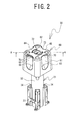
FIG. 2 is a perspective view of a main portion of astorage portion 30; -
FIG. 3 is an exploded oblique view of the main portion of thestorage portion 30; -
FIG. 4 is a sectional view of a cross section in the direction of a line A-A inFIG. 2 and a center shaft of astorage chamber 31; -
FIG. 5 is a plan view of astorage chamber cover 60; -
FIG. 6 is a bottom view of thestorage chamber cover 60; -
FIG. 7 is a right side view of thestorage chamber cover 60; -
FIG. 8 is a sectional view in the direction of a line B-B inFIG. 5 ; and -
FIG. 9 is a sectional view in the direction of a line C-C inFIG. 5 . - Hereinafter, a
storage chamber cover 60 according to an embodiment of the present invention and acloth bonding apparatus 1 that is provided with thestorage chamber cover 60 will be explained with reference to the drawings. - The configuration of the
cloth bonding apparatus 1 will be explained with reference toFIG. 1 . The lower right side, the upper left side, the upper right side, and the lower left side of theFIG. 1 respectively correspond to the front side, the rear side, the right side and the left side of thecloth bonding apparatus 1. Thecloth bonding apparatus 1 is provided with abed portion 2, apillar portion 3, and anarm portion 4. Thebed portion 2 is mounted to a table (not shown in the drawings). Thepillar portion 3 extends vertically upward from the right end of thebed portion 2. Thearm portion 4 is connected to the upper end of thepillar portion 3, and projects toward the left from the left side face of thepillar portion 3. - The
bed portion 2 is provided with a lower feed roller, a lower feed motor, and the like (not shown in the drawings) in its interior. The lower feed roller is positioned directly below anupper feed roller 17 and drives abelt 18. The lower feed motor drives the lower feed roller. Thebed portion 2 serves as a base that supports thepillar portion 3. Thepillar portion 3 supports thearm portion 4. Thearm portion 4 is provided with abeam portion 6, astorage portion 30, and apump case 20, in order starting from the rear. Thearm portion 4 is provided with various types of motors and the like in its interior. - The
beam portion 6 will be explained. Thebeam portion 6 is provided with a body portion 7, aspring support portion 8, and a column portion 9. The body portion 7 is a roughly rod-shaped member, and it extends in a horizontal direction to the left from the left rear edge of thearm portion 4. Thespring support portion 8 is plate-shaped and extends in a horizontal direction toward the front from the left end of the body portion 7. The column portion 9 extends diagonally downward toward the front from the body portion 7 at an angle of approximately 45 degrees from the horizontal plane. The lower end portion of the column portion 9 does not contact with thebed portion 2. - The
spring support portion 8 has a hole in its front end portion. An upper end portion of ashaft portion 12 is inserted into the hole, such that thespring support portion 8 supports theshaft portion 12 such that theshaft portion 12 can move up and down. Theshaft portion 12 is inserted through aspring 11. The column portion 9 has a shaft on the left side of its lower end that extends in the left-right direction. The column portion 9 support arear end portion 14 of aroller holding portion 13 by the shaft. Theroller holding portion 13 can pivot around the shaft such that afront end portion 15 moves in the up-down direction. - The
roller holding portion 13 support theupper feed roller 17 rotatably by thefront end portion 15. Theupper feed roller 17 is positioned close to and to the rear of acylindrical nozzle 25. Theroller holding portion 13 has ashaft support portion 16 on its upper side, slightly toward the front from the center. Theshaft support portion 16 supports the lower end of theshaft portion 12 that has been inserted through thespring 11. Thespring 11 is located between thespring support portion 8 and the lower end of theshaft portion 12. Thespring 11 energizes theroller holding portion 13 downward by energizing theshaft portion 12 downward. Theupper feed roller 17 and thebelt 18 move a cloth in the front-rear direction by rotating with the cloth pressed between them. - The
pump case 20 will be explained. Thepump case 20 is provided with afirst pump case 21 and asecond pump case 22. Thefirst pump case 21 has a roughly cubic shape and is connected by four screws to the left side face of thearm portion 4. The left side of thefirst pump case 21 forms a recessed portion, and a gear pump (not shown in the drawings) is provided in the recessed portion. Thesecond pump case 22 is connected by four screws to the left side of thefirst pump case 21 and covers the gear pump. Thefirst pump case 21 and thesecond pump case 22 form a pump chamber. The gear pump receives from thestorage portion 30 an adhesive that thestorage portion 30 has melted by heating and supplies an appropriate amount of the adhesive to thenozzle 25 under pressure. - The bottom portion of the
second pump case 22 holds asupport portion 24. Thesupport portion 24 extends toward the left from the bottom portion of thesecond pump case 22 and bends downward at its left end. The bottom end portion of thesupport portion 24 is slightly separated from the top surface of thebed portion 2. The bottom end of thesupport portion 24 holds the rod-shapednozzle 25. Thenozzle 25 projects toward the left from thesupport portion 24. The direction in which thenozzle 25 projects may also be toward the right. Thesupport portion 24 is provided with a feeding channel (not shown in the drawings) in its interior. The feeding channel extends from the gear pump to thenozzle 25. Thenozzle 25 discharges the adhesive that has passed through the feeding channel. Thepump case 20 and thesupport portion 24 are provided with heaters (not shown in the drawings) in their interiors. The heaters heat the adhesive that passes through thepump case 20 and thesupport portion 24. Therefore, the adhesive that thestorage portion 30 has heated does not harden on its way to thenozzle 25. - The
storage portion 30 has a roughly rectangular shape whose long direction is the up-down direction. Thestorage portion 30 extends vertically upward from the left side of thearm portion 4 and the rear side portion of thepump case 20. Thestorage portion 30 is mainly provided with astorage chamber 31, thestorage chamber cover 60, and a screw cover 44 (refer toFIG. 3 ). - The
storage portion 30 will be explained with reference toFIGS. 2 to 4 . In order to facilitate the explanation, a square tube-shaped outer frame of thestorage chamber 31 is not shown inFIGS. 2 to 4 . Thestorage chamber cover 60 is mounted on the upper portion of thestorage chamber 31. In order to melt the adhesive that is stored in its interior, the temperature of thestorage chamber 31 is increased by using heat from a storage chamber heater (that is described later). Thestorage chamber cover 60 is formed from a synthetic resin that has lower thermal conductivity than metal. Therefore, mounting thestorage chamber cover 60 on thestorage chamber 31 prevents the operator from being burned by directly touching the high-temperature storage chamber 31. As shown inFIGS. 3 and4 , thescrew cover 44 is fixed to the interior of thestorage chamber cover 60. Thescrew cover 44 is mounted on the upper portion of thestorage chamber 31 by being screwed onto it. Therefore, the operator can mount thescrew cover 44 and thestorage chamber cover 60 on the upper portion of thestorage chamber 31 at the same time simply by rotating thestorage chamber cover 60. - The
storage chamber 31 will be explained. Thestorage chamber 31 is provided with acartridge holding portion 32,leg portions 33, and anopening portion 39. - The
cartridge holding portion 32 is a cylindrical member. The operator sets acylindrical cartridge 37 that is filled with the adhesive in thecartridge holding portion 32 by inserting thecartridge 37 into an opening in the upper portion of thecartridge holding portion 32. Thecartridge holding portion 32 has ascrew hole 35 in each of the right rear and the left front of its upper end for fixing the openingportion 39 in place. Thecartridge 37 is provided with a ring-shaped packing 52 on its bottom face (the face at its upper end inFIG. 3 ). - The
leg portions 33 are formed on the right front side, the right rear side, the left front side and the left rear side of the outer circumferential face of thecartridge holding portion 32. Theleg portions 33 extend from the bottom end of thecartridge holding portion 32 to the center in the up-down direction. Theleg portions 33 hold the orientation of thecartridge holding portion 32. Theleg portions 33 on the right front side and the left rear side each have aheater insertion hole 34 that extends in the up-down direction. Each one of the heater insertion holes 34 holds one of the rod-shaped storage chamber heaters (not shown in the drawings) in its interior. Thecloth bonding apparatus 1 melts the adhesive that is inside thecartridge 37 by supplying electricity to the storage chamber heaters. - The opening
portion 39 is cylindrical. The openingportion 39 has twohelical grooves 40 in its outer circumferential face for mounting thescrew cover 44. The shapes of thehelical grooves 40 are axially symmetrical around the central axis of the openingportion 39. The bottom end portion of the openingportion 39 is provided with aflange portion 41 that is rectangular in a plan view. Theflange portion 41 has ascrew hole 42 in each of its right rear corner and its left front corner. The openingportion 39 is fixed in place on the upper portion of thecartridge holding portion 32 by aligning the positions of the twoscrew holes 42 in theflange portion 41 with the positions of the twoscrew holes 35 in thecartridge holding portion 32 and fastening the aligned screw holes together with screws. The central axis of thecylindrical opening portion 39 is aligned with the central axis of thecartridge holding portion 32. - The
screw cover 44 will be explained. As shown inFIG. 3 , thescrew cover 44 is provided with acircumference wall portion 45, an upperportion blocking portion 50, and an airline connecting portion 54. - The
circumference wall portion 45 is cylindrical. The inside diameter of thecircumference wall portion 45 and the outside diameter of the openingportion 39 of thestorage chamber 31 are equal. As shown inFIG. 4 , thecircumference wall portion 45 is provided with twolug portions 46 on its inner face. The twolug portions 46 project toward the inside of thecircumference wall portion 45. The twolug portions 46 are formed in positions that are symmetrical in relation to the central axis of thecircumference wall portion 45. The operator can mount thescrew cover 44 on the openingportion 39 by fitting each of the twolug portions 46 into the corresponding one of the twohelical grooves 40 and rotating thescrew cover 44 clockwise in a plan view. The operator can remove the screw cover 44 from the openingportion 39 by rotating thescrew cover 44 counterclockwise in a plan view. As shown inFIG. 3 , thecircumference wall portion 45 is provided with two slottedpieces 47 and twounslotted pieces 48 on the edge of its upper end. The top faces of theunslotted pieces 48 are flat. A slot-shapedfixing slot portion 49 is formed in the top face of each of the slottedpieces 47. The operator can easily fix thestorage chamber cover 60 and thescrew cover 44 in place using the slottedpieces 47 and theunslotted pieces 48. This will be explained in detail later. - The upper
portion blocking portion 50 is a roughly disc-shaped member with a recessed lower side. The upperportion blocking portion 50 is provided with a connectingportion 51 in the center of its top face. The connectingportion 51 guides air into the interior of thecartridge 37 from an air line (not shown in the drawings) that supplies compressed air. The force of the compressed air moves the adhesive in the interior of thecartridge 37 toward the gear pump inside the pump case 20 (refer toFIG. 1 ). As shown inFIG. 4 , the upperportion blocking portion 50 is fixed in place on the upper portion of thecircumference wall portion 45. The upperportion blocking portion 50 is provided, in the center of its bottom face, with aneedle 53 whose lower end projects sharply. When thescrew cover 44 is mounted on the openingportion 39, theneedle 53 penetrates to the inner side of the packing 52 of thecartridge 37 and makes a hole in the bottom face of thecartridge 37. The hole serves as an inflow channel for the compressed air into the interior of thecartridge 37. At the same time, the packing 52 of thecartridge 37 blocks the gap between thecartridge 37 and thescrew cover 44. The airline connecting portion 54 is connected to the air line (not shown in the drawings) and is fitted onto the connectingportion 51 from above. - The
storage chamber cover 60 will be explained. As shown inFIG. 2 , the shape of thestorage chamber cover 60 is roughly that of a square tube that is closed at its upper end. Thestorage chamber cover 60 is provided with atube portion 61 and atop wall 62. The length of one side of the upper portion of thetube portion 61 is slightly shorter than the length of one side of the lower portion. In a state in which thestorage chamber cover 60 has been mounted on thestorage chamber 31, thetube portion 61 covers the outer circumferential face (the side face) of the upper portion of thestorage chamber 31. Thetop wall 62 is formed in an opening at the top of thetube portion 61. In the state in which thestorage chamber cover 60 has been mounted on thestorage chamber 31, thetop wall 62 blocks the upper end of thestorage chamber 31. Therefore, thestorage chamber cover 60 reliably prevents the operator from directly touching the upper portion of the high-temperature storage chamber 31. Thetop wall 62 has a circular airline insertion hole 72 in its center. The airline insertion hole 72 allows the air line (not shown in the drawings) to pass into the interior.Arrows 73 that indicate the direction of rotation for removing thescrew cover 44 are formed on thetop wall 62 around the airline insertion hole 72. By looking at thearrows 73, the operator can easily determine the direction of rotation for removing thescrew cover 44. - The
storage chamber cover 60 is mainly provided with recessedportions 63 to 66, vent holes 68, projectingportions 70, andcover fixing portions 75. - The recessed
portions 63 to 66 will be explained. As shown inFIGS. 2 ,5 , and6 , thetube portion 61 includes a front recessedportion 63, a rear recessedportion 64, a right recessedportion 65, and a left recessed portion 66 (hereinafter collectively called the recessedportions 63 to 66), with shapes that are recessed toward the inside. The front recessedportion 63 is formed on the front face of thetube portion 61, the rear recessedportion 64 is formed on the rear face, the right recessedportion 65 is formed on the right face, and the left recessedportion 66 is formed on the left face. The shapes of the recessedportions 63 to 66 are shapes that are curved smoothly toward the inside. The shapes of the four recessedportions 63 to 66 are all the same except for the presence or absence of the vent holes 68, which will be described later. The recessedportions 63 to 66 are formed such that they extend toward the upper end of thetube portion 61 from slightly below the centers of the four faces of thetube portion 61. - When the operator rotates the
storage chamber cover 60 by hand, the operator can place his fingers in the recessedportions 63 to 66 and the palm of his hand on the corners of thetube portion 61. Therefore, the operator can easily grasp the corners of thetube portion 61 and rotate thestorage chamber cover 60. Even when the operator is wearing heat-resistant gloves, the operator can easily and safely perform the mounting and the removing of thestorage chamber cover 60 and thescrew cover 44. - The vent holes 68 will be explained. As shown in
FIGS. 2 ,5 , and6 , thestorage chamber cover 60 has at least one of the vent holes 68 on at least one side of thetube portion 61 and thetop wall 62. Air whose temperature has been raised by the heating of thestorage chamber 31 passes through the vent holes 68 and flows to the outside of thestorage chamber cover 60. Therefore, the temperature of thestorage chamber cover 60 is lower than if the vent holes 68 are not formed. The operator can perform work more safely. - The
storage chamber cover 60 according to the present embodiment has the vent holes 68 in thetube portion 61 and not in thetop wall 62. Therefore, the vent holes 68 face toward the side. Because the vent holes 68 in thestorage chamber cover 60 face toward the side, the possibility is reduced that dirt that falls from above will penetrate into the interior ofstorage chamber cover 60 through the vent holes 68. As shown inFIGS. 5 to 7 , thestorage chamber cover 60 has five of the vent holes 68 in each of the upper edge portion of the right recessedportion 65 and the upper edge portion of the left recessedportion 66. Air that has reached a high temperature rises in the interior of thestorage chamber cover 60. Therefore, thestorage chamber cover 60 can flow the high-temperature air efficiently to the outside through the vent holes 68 in thetop wall 62 side of the tube portion 61 (in the upper portion of the tube portion 61). - As described previously, the operator places his fingers in the recessed
portions 63 to 66 when the operator rotates thestorage chamber cover 60. The operator's fingers can easily be placed in the areas of the right recessedportion 65 and the left recessedportion 66 where the vent holes 68 have been formed. Therefore, the operator can easily and safely perform the mounting and the removing of thestorage chamber cover 60 and thescrew cover 44. - When the
storage chamber cover 60 is rotated until the lug portions 46 (refer toFIG. 4 ) come into contact with the ends of thehelical grooves 40, the front recessedportion 63 stops such that it faces the front side. The operator performs work at the front side of thecloth bonding apparatus 1. Thestorage chamber cover 60 has the vent holes 68 in the right recessedportion 65 and the left recessedportion 66, and does not have the vent holes 68 in the front recessedportion 63. Therefore, thestorage chamber cover 60 can keep the operator out of the high-temperature air that has been discharged from the vent holes 68 to strike the operator who is performing work at the front side. - The projecting
portions 70 will be explained. As shown inFIG 8 , thestorage chamber cover 60 is provided with the projectingportions 70 at the upper edges of the recessedportions 63 to 66 (only the recessedportions FIG. 8 ). The projectingportions 70 project in the direction away from the central axis (toward the outer side) of thetube portion 61. When the operator carries thestorage chamber cover 60 with his hand on the recessedportions 63 to 66, the operator's hand gets a hold on the projectingportions 70. Therefore, the projectingportions 70 can reduce the possibility that the operator will drop thestorage chamber cover 60, even when the operator is wearing the slippery heat-resistant gloves. As shown inFIGS. 7 and8 , the projectingportion 70 at the upper edge of the right recessedportion 65 and the projectingportion 70 at the upper edge of the left recessedportion 66 are formed at the upper edges of the vent holes 68. Therefore, the projectingportions 70 can reduce the possibility that dirt will enter through the vent holes 68. - The
cover fixing portions 75 will be explained. As shown inFIGS. 5 and6 , thestorage chamber cover 60 is provided with thecover fixing portions 75 at the right front side, the right rear side, the left front side, and the left rear side. Thecover fixing portions 75 fix thescrew cover 44 to thestorage chamber cover 60. -
FIG. 9 is a vertical sectional view of thecover fixing portion 75 at the right front side of thestorage chamber cover 60. Thecover fixing portion 75 is provided with aconcave portion 76, ascrew hole 77, and a fixingscrew 85. Theconcave portion 76 is a portion that is concave downward from the wall surface of thetop wall 62. Thescrew hole 77 is formed in the bottom portion of theconcave portion 76. Themetal fixing screw 85 fixes thescrew cover 44 to thestorage chamber cover 60 by fastening the screw hole in the slottedpiece 47 of the screw cover 44 (refer toFIG. 3 ) to thescrew hole 77 of theconcave portion 76. Once thescrew cover 44 is fixed to thestorage chamber cover 60, the axis of rotation of thescrew cover 44 is aligned with the central axis of thetube portion 61 of thestorage chamber cover 60. Because thescrew hole 77 is formed in the bottom portion of theconcave portion 76, the head of the fixingscrew 85 is not exposed on the surface of thetop wall 62. It is therefore difficult for the operator to touch themetal fixing screw 85, which has high thermal conductivity, so the possibility that the operator will be burned is reduced. - As shown in
FIG. 9 , theconcave portions 76 at the right front side and the left rear side of thestorage chamber cover 60 are provided withrotation preventing portions 80 at their lower ends. Therotation preventing portions 80 are projecting portions that project farther downward from the lower ends of theconcave portions 76. Therotation preventing portions 80 engage into the fixingconcave portions 49 that are formed in the slottedpieces 47 of thescrew cover 44. Engaging therotation preventing portions 80 into the fixingconcave portions 49 prevents the screw cover 44 from rotating in relation to thestorage chamber cover 60. Therefore, thescrew cover 44 can be fixed more reliably than when thescrew cover 44 is fixed to thestorage chamber cover 60 only by the fixing screws 85. The operator fastens the fixing screws 85 after fitting therotation preventing portions 80 into the fixingconcave portions 49, so thescrew cover 44 can easily be fixed to thestorage chamber cover 60 at the proper angle. - As shown in
FIG. 6 , of the fourcover fixing portions 75, thecover fixing portions 75 at the right front side and the left rear side of thestorage chamber cover 60 have therotation preventing portions 80. Thecover fixing portions 75 at the right rear side and the left front side of thestorage chamber cover 60 do not have therotation preventing portions 80. Therefore, the shape of thestorage chamber cover 60 is axially symmetrical around the central axis of thetube portion 61. As explained previously, thescrew cover 44 is provided with the slottedpieces 47 at the right front side and the left rear side and is provided with theunslotted pieces 48 at the right rear side and the left front side. Therotation preventing portions 80 engage with the fixingconcave portions 49 of the slottedpieces 47 only when thestorage chamber cover 60 is adjusted to the predetermined angle in relation to thescrew cover 44. When therotation preventing portions 80 fits into the fixingconcave portions 49, thestorage chamber cover 60 is in the appropriate orientation, where the vent holes 68 face the right side and the left side. Therefore, the operator can easily fix thescrew cover 44 to thestorage chamber cover 60 by adjusting the orientation of thestorage chamber cover 60. - According to the present embodiment, by rotating the
storage chamber cover 60, the operator can firmly mount thescrew cover 44, which has been fixed to the inner side of thestorage chamber cover 60, on the openingportion 39 of thestorage chamber 31. Therefore, the operator can reliably seal off the interior portion of thestorage chamber 31. Because thestorage chamber cover 60 is positioned on the outside of thescrew cover 44, the temperature of thestorage chamber cover 60 is lower than the temperature of thescrew cover 44 when the temperature of thestorage chamber 31 is high. Therefore, the operator can mount and remove thescrew cover 44 more safely than when the operator rotates thescrew cover 44 by touching thescrew cover 44 directly. Thetube portion 61 of thestorage chamber cover 60 has the recessedportions 63 to 66 that are recessed toward the inside. The operator rotates thestorage chamber cover 60 by placing his fingers on the recessedportions 63 to 66, so his hand tends not to slip, even when he is wearing the heat-resistant gloves. Therefore, the operator can easily and safely perform the mounting and the removing of thescrew cover 44. - Various modifications can be made to the embodiment that is described above. For example, the
tube portion 61 may be a round tube instead of a square tube. Even when thetube portion 61 is a round tube, the operator can easily rotate thestorage chamber cover 60 by placing his hand on the recessedportions 63 to 66 that are formed in the side faces of thetube portion 61. The number, the shapes, and the like of the recessedportions 63 to 66 can be modified. For example, the shapes of the recessedportions 63 to 66 do not have to be curved smoothly toward the inside. The recessedportions 63 to 66 may also extend from the upper edges to the lower edges of the wall surfaces of thetube portion 61. The recessedportions 63 to 66 may also be formed such that only the central portions of the wall surfaces are recessed. Thestorage chamber cover 60 may also have the recessed portions only on the right side face and the left side face of thetube portion 61. - The structure for fixing the
screw cover 44 to thestorage chamber cover 60 may also be modified. For example, thescrew cover 44 may also be fixed to thestorage chamber cover 60 using clips or the like instead of the fixing screws 85. It is not necessary for the central axis of thetube portion 61 of thestorage chamber cover 60 to be aligned to the axis of rotation of thescrew cover 44, as long as it is parallel to the axis of rotation of thescrew cover 44. Even if the axis of rotation of thetube portion 61 and the axis of rotation of thescrew cover 44 are not aligned, the operator can perform the mounting and the removing of thescrew cover 44 by rotating thestorage chamber cover 60. - The shapes, the positions, the number, and the like of the vent holes 68 can be modified. For example, the vent holes 68 may also be formed in the
top wall 62. The vent holes 68 may also be formed in any location other than the recessedportions 63 to 66 of thetube portion 61. It is preferable for the vent holes 68 to be formed in the upper edge portions of the recessedportions storage chamber cover 60 may also have a single horizontally long hole instead of the five vent holes 68. - In the embodiment that is described above, the
rotation preventing portions 80 have projecting shapes, and the fixingconcave portions 49 of thescrew cover 44 have slot shapes. Conversely, therotation preventing portions 80 may have slot shapes, and thescrew cover 44 may be provided with fixing projecting portions. The recessed portions that form the slottedpieces 47 do not have to be slot-shaped. The recessed portions may be any shape that fits together with therotation preventing portions 80.
Claims (6)
- A storage chamber cover (60) that is mounted on a storage chamber (31) that stores an adhesive inside and that melts the stored adhesive by heating, characterized by comprising:a tube portion (61) that has a tube shape and that covers an outer circumference of the storage chamber (31);a top wall (62) that is formed on one of two openings in the tube portion (61); anda cover fixing portion (75) that fixes, on an inner side of the tube portion (61), a screw cover (44) that is mounted by being screwed onto an opening portion (39) of the storage chamber (31), in a state in which an axis of rotation of the screw cover (44) and a central axis of the tube portion (61) are parallel to one another,wherein at least one recessed portion (63-66) that is recessed toward the inside is formed in the tube portion (61).
- The storage chamber cover (60) according to claim 1, characterized by further comprising:a vent hole (68) is formed in at least one of the tube portion (61) and the top wall (62).
- The storage chamber cover (60) according to claim 2, characterized in that
the storage chamber cover (60) is mounted on an upper portion of the storage chamber (31) such that the top wall (62) covers the top of the storage chamber (31), and
the vent hole (68) is formed in the top wall (62) side in the recessed portion (63-66). - The storage chamber cover (60) according to any one of claims 1 to 3, characterized by further comprising:a projecting portion (70) that is formed on an upper edge portion of the recessed portion (63-66) to project in a direction away from the central axis of the tube portion (61).
- The storage chamber cover (60) according to any one of claims 1 to 4, characterized in that
the cover fixing portion (75) is provided with a fixing screw (85) that is screwed into a screw hole (77) formed in the screw cover (44) and with a rotation preventing portion (80) that fits together with one of a fixing concave portion (49) and a fixing projecting portion formed in the screw cover (44). - A cloth bonding apparatus (1), characterized by comprising:the storage chamber cover (60), the storage chamber (31), and the screw cover (44) described in any one of claims 1 to 5;wherein cloths are bonded with an adhesive that is stored in the storage chamber (31).
Applications Claiming Priority (1)
| Application Number | Priority Date | Filing Date | Title |
|---|---|---|---|
| JP2010265872A JP5609590B2 (en) | 2010-11-30 | 2010-11-30 | Storage room cover and cloth bonding apparatus |
Publications (3)
| Publication Number | Publication Date |
|---|---|
| EP2457669A2 true EP2457669A2 (en) | 2012-05-30 |
| EP2457669A3 EP2457669A3 (en) | 2016-12-07 |
| EP2457669B1 EP2457669B1 (en) | 2019-04-03 |
Family
ID=45607501
Family Applications (1)
| Application Number | Title | Priority Date | Filing Date |
|---|---|---|---|
| EP11187562.1A Not-in-force EP2457669B1 (en) | 2010-11-30 | 2011-11-02 | Assembly comprising storage chamber cover and storage chamber, and cloth bonding apparatus comprising the assembly |
Country Status (3)
| Country | Link |
|---|---|
| EP (1) | EP2457669B1 (en) |
| JP (1) | JP5609590B2 (en) |
| CN (1) | CN102525000B (en) |
Cited By (1)
| Publication number | Priority date | Publication date | Assignee | Title |
|---|---|---|---|---|
| CN114377905A (en) * | 2020-10-16 | 2022-04-22 | 汉达精密电子(昆山)有限公司 | Three-axis micro-regulator |
Citations (1)
| Publication number | Priority date | Publication date | Assignee | Title |
|---|---|---|---|---|
| JP2010222764A (en) | 2009-03-25 | 2010-10-07 | Brother Ind Ltd | Cloth bonding apparatus and lid control program |
Family Cites Families (7)
| Publication number | Priority date | Publication date | Assignee | Title |
|---|---|---|---|---|
| JPH08175559A (en) * | 1994-12-27 | 1996-07-09 | Kubota Corp | Fuel tank cap |
| JP2006076582A (en) * | 2004-09-07 | 2006-03-23 | Yanmar Co Ltd | Cap for tank |
| US20070075083A1 (en) * | 2005-10-04 | 2007-04-05 | Mc Clellan W T | Non-contaminating milk or food container seal and seal removal system |
| US8016734B2 (en) * | 2007-03-22 | 2011-09-13 | Nordson Corporation | Apparatus and methods for non-contact adhesive dispensing to manufacture bags |
| JP5251561B2 (en) * | 2009-02-04 | 2013-07-31 | ブラザー工業株式会社 | Cloth bonding apparatus and bonding program |
| JP2010222763A (en) * | 2009-03-25 | 2010-10-07 | Brother Ind Ltd | Cloth bonding apparatus and pressure control program |
| JP2010222762A (en) * | 2009-03-25 | 2010-10-07 | Brother Ind Ltd | Cloth bonding equipment |
-
2010
- 2010-11-30 JP JP2010265872A patent/JP5609590B2/en active Active
-
2011
- 2011-09-29 CN CN201110308091.1A patent/CN102525000B/en active Active
- 2011-11-02 EP EP11187562.1A patent/EP2457669B1/en not_active Not-in-force
Patent Citations (1)
| Publication number | Priority date | Publication date | Assignee | Title |
|---|---|---|---|---|
| JP2010222764A (en) | 2009-03-25 | 2010-10-07 | Brother Ind Ltd | Cloth bonding apparatus and lid control program |
Cited By (1)
| Publication number | Priority date | Publication date | Assignee | Title |
|---|---|---|---|---|
| CN114377905A (en) * | 2020-10-16 | 2022-04-22 | 汉达精密电子(昆山)有限公司 | Three-axis micro-regulator |
Also Published As
| Publication number | Publication date |
|---|---|
| EP2457669B1 (en) | 2019-04-03 |
| JP2012116494A (en) | 2012-06-21 |
| CN102525000A (en) | 2012-07-04 |
| EP2457669A3 (en) | 2016-12-07 |
| JP5609590B2 (en) | 2014-10-22 |
| CN102525000B (en) | 2014-10-29 |
Similar Documents
| Publication | Publication Date | Title |
|---|---|---|
| JP6269505B2 (en) | Shelf holder | |
| KR102048543B1 (en) | Auto assembling system for fuse cock | |
| EP2457669B1 (en) | Assembly comprising storage chamber cover and storage chamber, and cloth bonding apparatus comprising the assembly | |
| KR101943968B1 (en) | Apparatus for manufacturing hydrogel pack for skin care and contorl method thereof | |
| US20090294432A1 (en) | Cooktop, heater support device of cooktop, and heater support spring of cooktop | |
| CA2896748A1 (en) | Welding apparatus for conveyor belts and method | |
| RU2018127666A (en) | HEAT AIR CONDITIONING DEVICE FOR INJECTION SYSTEM | |
| EP3075518A1 (en) | Bonding device | |
| BR112013031644B1 (en) | TEMPLATE SHOE SET WITH SUPPORT SURFACE MECHANISM, METHOD FOR HOLDING A TEMPLATE, AND TEMPLATE FOR USE WITH THE SAME | |
| CN108237689B (en) | 3D printer | |
| KR20150094414A (en) | Extruder of 3D printer | |
| CN111451177B (en) | Fixing fixtures and rubbing equipment for rubbing equipment | |
| JP7739762B2 (en) | injection molding equipment | |
| KR102209136B1 (en) | Apparatus for cutting a window frame and System for manufacturing a window frame including the same | |
| TWI611066B (en) | Sewing machine | |
| KR20160028659A (en) | Burring apparatus for plastic packaging | |
| CN110167390A (en) | Utilize the beautifying skin film manufacturing device and its control method of hydrogel | |
| KR20190001382U (en) | Washing device for safety helmet | |
| CN215196997U (en) | Sample heat-preservation containing box for bovine serum albumin | |
| KR102174400B1 (en) | Heat Systolic | |
| JP6929534B2 (en) | Twin trowel type soldering device | |
| KR20240095612A (en) | Residual resin removal device for 3d-printer products | |
| KR102126041B1 (en) | Multi coater | |
| JP2004296330A (en) | Sealer application device for battery | |
| KR101744622B1 (en) | The device of supplying oxygen |
Legal Events
| Date | Code | Title | Description |
|---|---|---|---|
| PUAI | Public reference made under article 153(3) epc to a published international application that has entered the european phase |
Free format text: ORIGINAL CODE: 0009012 |
|
| AK | Designated contracting states |
Kind code of ref document: A2 Designated state(s): AL AT BE BG CH CY CZ DE DK EE ES FI FR GB GR HR HU IE IS IT LI LT LU LV MC MK MT NL NO PL PT RO RS SE SI SK SM TR |
|
| AX | Request for extension of the european patent |
Extension state: BA ME |
|
| PUAL | Search report despatched |
Free format text: ORIGINAL CODE: 0009013 |
|
| AK | Designated contracting states |
Kind code of ref document: A3 Designated state(s): AL AT BE BG CH CY CZ DE DK EE ES FI FR GB GR HR HU IE IS IT LI LT LU LV MC MK MT NL NO PL PT RO RS SE SI SK SM TR |
|
| AX | Request for extension of the european patent |
Extension state: BA ME |
|
| RIC1 | Information provided on ipc code assigned before grant |
Ipc: B29C 65/52 20060101ALN20161102BHEP Ipc: A41H 43/04 20060101ALN20161102BHEP Ipc: D06H 5/00 20060101ALN20161102BHEP Ipc: B05C 5/04 20060101AFI20161102BHEP |
|
| STAA | Information on the status of an ep patent application or granted ep patent |
Free format text: STATUS: REQUEST FOR EXAMINATION WAS MADE |
|
| 17P | Request for examination filed |
Effective date: 20170606 |
|
| RBV | Designated contracting states (corrected) |
Designated state(s): AL AT BE BG CH CY CZ DE DK EE ES FI FR GB GR HR HU IE IS IT LI LT LU LV MC MK MT NL NO PL PT RO RS SE SI SK SM TR |
|
| STAA | Information on the status of an ep patent application or granted ep patent |
Free format text: STATUS: EXAMINATION IS IN PROGRESS |
|
| 17Q | First examination report despatched |
Effective date: 20171212 |
|
| GRAP | Despatch of communication of intention to grant a patent |
Free format text: ORIGINAL CODE: EPIDOSNIGR1 |
|
| STAA | Information on the status of an ep patent application or granted ep patent |
Free format text: STATUS: GRANT OF PATENT IS INTENDED |
|
| RIC1 | Information provided on ipc code assigned before grant |
Ipc: B29C 65/48 20060101ALI20181005BHEP Ipc: B05C 5/04 20060101AFI20181005BHEP Ipc: B05C 5/02 20060101ALI20181005BHEP Ipc: B29C 65/00 20060101ALI20181005BHEP Ipc: B29C 65/52 20060101ALI20181005BHEP |
|
| INTG | Intention to grant announced |
Effective date: 20181025 |
|
| GRAS | Grant fee paid |
Free format text: ORIGINAL CODE: EPIDOSNIGR3 |
|
| GRAA | (expected) grant |
Free format text: ORIGINAL CODE: 0009210 |
|
| STAA | Information on the status of an ep patent application or granted ep patent |
Free format text: STATUS: THE PATENT HAS BEEN GRANTED |
|
| AK | Designated contracting states |
Kind code of ref document: B1 Designated state(s): AL AT BE BG CH CY CZ DE DK EE ES FI FR GB GR HR HU IE IS IT LI LT LU LV MC MK MT NL NO PL PT RO RS SE SI SK SM TR |
|
| REG | Reference to a national code |
Ref country code: GB Ref legal event code: FG4D |
|
| REG | Reference to a national code |
Ref country code: CH Ref legal event code: EP Ref country code: AT Ref legal event code: REF Ref document number: 1115078 Country of ref document: AT Kind code of ref document: T Effective date: 20190415 |
|
| REG | Reference to a national code |
Ref country code: DE Ref legal event code: R096 Ref document number: 602011057706 Country of ref document: DE |
|
| REG | Reference to a national code |
Ref country code: IE Ref legal event code: FG4D |
|
| REG | Reference to a national code |
Ref country code: NL Ref legal event code: MP Effective date: 20190403 |
|
| REG | Reference to a national code |
Ref country code: LT Ref legal event code: MG4D |
|
| REG | Reference to a national code |
Ref country code: AT Ref legal event code: MK05 Ref document number: 1115078 Country of ref document: AT Kind code of ref document: T Effective date: 20190403 |
|
| PG25 | Lapsed in a contracting state [announced via postgrant information from national office to epo] |
Ref country code: NL Free format text: LAPSE BECAUSE OF FAILURE TO SUBMIT A TRANSLATION OF THE DESCRIPTION OR TO PAY THE FEE WITHIN THE PRESCRIBED TIME-LIMIT Effective date: 20190403 |
|
| PG25 | Lapsed in a contracting state [announced via postgrant information from national office to epo] |
Ref country code: CZ Free format text: LAPSE BECAUSE OF FAILURE TO SUBMIT A TRANSLATION OF THE DESCRIPTION OR TO PAY THE FEE WITHIN THE PRESCRIBED TIME-LIMIT Effective date: 20190403 Ref country code: NO Free format text: LAPSE BECAUSE OF FAILURE TO SUBMIT A TRANSLATION OF THE DESCRIPTION OR TO PAY THE FEE WITHIN THE PRESCRIBED TIME-LIMIT Effective date: 20190703 Ref country code: HR Free format text: LAPSE BECAUSE OF FAILURE TO SUBMIT A TRANSLATION OF THE DESCRIPTION OR TO PAY THE FEE WITHIN THE PRESCRIBED TIME-LIMIT Effective date: 20190403 Ref country code: ES Free format text: LAPSE BECAUSE OF FAILURE TO SUBMIT A TRANSLATION OF THE DESCRIPTION OR TO PAY THE FEE WITHIN THE PRESCRIBED TIME-LIMIT Effective date: 20190403 Ref country code: LT Free format text: LAPSE BECAUSE OF FAILURE TO SUBMIT A TRANSLATION OF THE DESCRIPTION OR TO PAY THE FEE WITHIN THE PRESCRIBED TIME-LIMIT Effective date: 20190403 Ref country code: SE Free format text: LAPSE BECAUSE OF FAILURE TO SUBMIT A TRANSLATION OF THE DESCRIPTION OR TO PAY THE FEE WITHIN THE PRESCRIBED TIME-LIMIT Effective date: 20190403 Ref country code: PT Free format text: LAPSE BECAUSE OF FAILURE TO SUBMIT A TRANSLATION OF THE DESCRIPTION OR TO PAY THE FEE WITHIN THE PRESCRIBED TIME-LIMIT Effective date: 20190803 Ref country code: AL Free format text: LAPSE BECAUSE OF FAILURE TO SUBMIT A TRANSLATION OF THE DESCRIPTION OR TO PAY THE FEE WITHIN THE PRESCRIBED TIME-LIMIT Effective date: 20190403 Ref country code: FI Free format text: LAPSE BECAUSE OF FAILURE TO SUBMIT A TRANSLATION OF THE DESCRIPTION OR TO PAY THE FEE WITHIN THE PRESCRIBED TIME-LIMIT Effective date: 20190403 |
|
| PG25 | Lapsed in a contracting state [announced via postgrant information from national office to epo] |
Ref country code: RS Free format text: LAPSE BECAUSE OF FAILURE TO SUBMIT A TRANSLATION OF THE DESCRIPTION OR TO PAY THE FEE WITHIN THE PRESCRIBED TIME-LIMIT Effective date: 20190403 Ref country code: LV Free format text: LAPSE BECAUSE OF FAILURE TO SUBMIT A TRANSLATION OF THE DESCRIPTION OR TO PAY THE FEE WITHIN THE PRESCRIBED TIME-LIMIT Effective date: 20190403 Ref country code: GR Free format text: LAPSE BECAUSE OF FAILURE TO SUBMIT A TRANSLATION OF THE DESCRIPTION OR TO PAY THE FEE WITHIN THE PRESCRIBED TIME-LIMIT Effective date: 20190704 Ref country code: PL Free format text: LAPSE BECAUSE OF FAILURE TO SUBMIT A TRANSLATION OF THE DESCRIPTION OR TO PAY THE FEE WITHIN THE PRESCRIBED TIME-LIMIT Effective date: 20190403 Ref country code: BG Free format text: LAPSE BECAUSE OF FAILURE TO SUBMIT A TRANSLATION OF THE DESCRIPTION OR TO PAY THE FEE WITHIN THE PRESCRIBED TIME-LIMIT Effective date: 20190703 |
|
| PG25 | Lapsed in a contracting state [announced via postgrant information from national office to epo] |
Ref country code: IS Free format text: LAPSE BECAUSE OF FAILURE TO SUBMIT A TRANSLATION OF THE DESCRIPTION OR TO PAY THE FEE WITHIN THE PRESCRIBED TIME-LIMIT Effective date: 20190803 Ref country code: AT Free format text: LAPSE BECAUSE OF FAILURE TO SUBMIT A TRANSLATION OF THE DESCRIPTION OR TO PAY THE FEE WITHIN THE PRESCRIBED TIME-LIMIT Effective date: 20190403 |
|
| REG | Reference to a national code |
Ref country code: DE Ref legal event code: R097 Ref document number: 602011057706 Country of ref document: DE |
|
| PG25 | Lapsed in a contracting state [announced via postgrant information from national office to epo] |
Ref country code: RO Free format text: LAPSE BECAUSE OF FAILURE TO SUBMIT A TRANSLATION OF THE DESCRIPTION OR TO PAY THE FEE WITHIN THE PRESCRIBED TIME-LIMIT Effective date: 20190403 Ref country code: SK Free format text: LAPSE BECAUSE OF FAILURE TO SUBMIT A TRANSLATION OF THE DESCRIPTION OR TO PAY THE FEE WITHIN THE PRESCRIBED TIME-LIMIT Effective date: 20190403 Ref country code: DK Free format text: LAPSE BECAUSE OF FAILURE TO SUBMIT A TRANSLATION OF THE DESCRIPTION OR TO PAY THE FEE WITHIN THE PRESCRIBED TIME-LIMIT Effective date: 20190403 Ref country code: EE Free format text: LAPSE BECAUSE OF FAILURE TO SUBMIT A TRANSLATION OF THE DESCRIPTION OR TO PAY THE FEE WITHIN THE PRESCRIBED TIME-LIMIT Effective date: 20190403 |
|
| PLBE | No opposition filed within time limit |
Free format text: ORIGINAL CODE: 0009261 |
|
| STAA | Information on the status of an ep patent application or granted ep patent |
Free format text: STATUS: NO OPPOSITION FILED WITHIN TIME LIMIT |
|
| PG25 | Lapsed in a contracting state [announced via postgrant information from national office to epo] |
Ref country code: SM Free format text: LAPSE BECAUSE OF FAILURE TO SUBMIT A TRANSLATION OF THE DESCRIPTION OR TO PAY THE FEE WITHIN THE PRESCRIBED TIME-LIMIT Effective date: 20190403 Ref country code: IT Free format text: LAPSE BECAUSE OF FAILURE TO SUBMIT A TRANSLATION OF THE DESCRIPTION OR TO PAY THE FEE WITHIN THE PRESCRIBED TIME-LIMIT Effective date: 20190403 |
|
| 26N | No opposition filed |
Effective date: 20200106 |
|
| PG25 | Lapsed in a contracting state [announced via postgrant information from national office to epo] |
Ref country code: TR Free format text: LAPSE BECAUSE OF FAILURE TO SUBMIT A TRANSLATION OF THE DESCRIPTION OR TO PAY THE FEE WITHIN THE PRESCRIBED TIME-LIMIT Effective date: 20190403 |
|
| PGFP | Annual fee paid to national office [announced via postgrant information from national office to epo] |
Ref country code: GB Payment date: 20191029 Year of fee payment: 9 |
|
| PG25 | Lapsed in a contracting state [announced via postgrant information from national office to epo] |
Ref country code: SI Free format text: LAPSE BECAUSE OF FAILURE TO SUBMIT A TRANSLATION OF THE DESCRIPTION OR TO PAY THE FEE WITHIN THE PRESCRIBED TIME-LIMIT Effective date: 20190403 |
|
| REG | Reference to a national code |
Ref country code: DE Ref legal event code: R119 Ref document number: 602011057706 Country of ref document: DE |
|
| REG | Reference to a national code |
Ref country code: CH Ref legal event code: PL |
|
| PG25 | Lapsed in a contracting state [announced via postgrant information from national office to epo] |
Ref country code: LU Free format text: LAPSE BECAUSE OF NON-PAYMENT OF DUE FEES Effective date: 20191102 Ref country code: MC Free format text: LAPSE BECAUSE OF FAILURE TO SUBMIT A TRANSLATION OF THE DESCRIPTION OR TO PAY THE FEE WITHIN THE PRESCRIBED TIME-LIMIT Effective date: 20190403 Ref country code: CH Free format text: LAPSE BECAUSE OF NON-PAYMENT OF DUE FEES Effective date: 20191130 Ref country code: LI Free format text: LAPSE BECAUSE OF NON-PAYMENT OF DUE FEES Effective date: 20191130 |
|
| REG | Reference to a national code |
Ref country code: BE Ref legal event code: MM Effective date: 20191130 |
|
| PG25 | Lapsed in a contracting state [announced via postgrant information from national office to epo] |
Ref country code: IE Free format text: LAPSE BECAUSE OF NON-PAYMENT OF DUE FEES Effective date: 20191102 Ref country code: FR Free format text: LAPSE BECAUSE OF NON-PAYMENT OF DUE FEES Effective date: 20191130 Ref country code: DE Free format text: LAPSE BECAUSE OF NON-PAYMENT OF DUE FEES Effective date: 20200603 |
|
| PG25 | Lapsed in a contracting state [announced via postgrant information from national office to epo] |
Ref country code: BE Free format text: LAPSE BECAUSE OF NON-PAYMENT OF DUE FEES Effective date: 20191130 |
|
| PG25 | Lapsed in a contracting state [announced via postgrant information from national office to epo] |
Ref country code: CY Free format text: LAPSE BECAUSE OF FAILURE TO SUBMIT A TRANSLATION OF THE DESCRIPTION OR TO PAY THE FEE WITHIN THE PRESCRIBED TIME-LIMIT Effective date: 20190403 |
|
| GBPC | Gb: european patent ceased through non-payment of renewal fee |
Effective date: 20201102 |
|
| PG25 | Lapsed in a contracting state [announced via postgrant information from national office to epo] |
Ref country code: HU Free format text: LAPSE BECAUSE OF FAILURE TO SUBMIT A TRANSLATION OF THE DESCRIPTION OR TO PAY THE FEE WITHIN THE PRESCRIBED TIME-LIMIT; INVALID AB INITIO Effective date: 20111102 Ref country code: MT Free format text: LAPSE BECAUSE OF FAILURE TO SUBMIT A TRANSLATION OF THE DESCRIPTION OR TO PAY THE FEE WITHIN THE PRESCRIBED TIME-LIMIT Effective date: 20190403 |
|
| PG25 | Lapsed in a contracting state [announced via postgrant information from national office to epo] |
Ref country code: GB Free format text: LAPSE BECAUSE OF NON-PAYMENT OF DUE FEES Effective date: 20201102 |
|
| PG25 | Lapsed in a contracting state [announced via postgrant information from national office to epo] |
Ref country code: MK Free format text: LAPSE BECAUSE OF FAILURE TO SUBMIT A TRANSLATION OF THE DESCRIPTION OR TO PAY THE FEE WITHIN THE PRESCRIBED TIME-LIMIT Effective date: 20190403 |