EP2457286B1 - System und verfahren zur verbesserung der mimo-leistung von drahtlosen kommunikationen auf fahrzeugbasis - Google Patents
System und verfahren zur verbesserung der mimo-leistung von drahtlosen kommunikationen auf fahrzeugbasis Download PDFInfo
- Publication number
- EP2457286B1 EP2457286B1 EP10802713.7A EP10802713A EP2457286B1 EP 2457286 B1 EP2457286 B1 EP 2457286B1 EP 10802713 A EP10802713 A EP 10802713A EP 2457286 B1 EP2457286 B1 EP 2457286B1
- Authority
- EP
- European Patent Office
- Prior art keywords
- antenna elements
- antenna
- sub
- arrays
- subset
- Prior art date
- Legal status (The legal status is an assumption and is not a legal conclusion. Google has not performed a legal analysis and makes no representation as to the accuracy of the status listed.)
- Active
Links
Images


Classifications
-
- H—ELECTRICITY
- H01—ELECTRIC ELEMENTS
- H01Q—ANTENNAS, i.e. RADIO AERIALS
- H01Q3/00—Arrangements for changing or varying the orientation or the shape of the directional pattern of the waves radiated from an antenna or antenna system
- H01Q3/24—Arrangements for changing or varying the orientation or the shape of the directional pattern of the waves radiated from an antenna or antenna system varying the orientation by switching energy from one active radiating element to another, e.g. for beam switching
-
- H—ELECTRICITY
- H01—ELECTRIC ELEMENTS
- H01Q—ANTENNAS, i.e. RADIO AERIALS
- H01Q1/00—Details of, or arrangements associated with, antennas
- H01Q1/27—Adaptation for use in or on movable bodies
- H01Q1/32—Adaptation for use in or on road or rail vehicles
- H01Q1/3208—Adaptation for use in or on road or rail vehicles characterised by the application wherein the antenna is used
- H01Q1/3233—Adaptation for use in or on road or rail vehicles characterised by the application wherein the antenna is used particular used as part of a sensor or in a security system, e.g. for automotive radar, navigation systems
-
- H—ELECTRICITY
- H01—ELECTRIC ELEMENTS
- H01Q—ANTENNAS, i.e. RADIO AERIALS
- H01Q21/00—Antenna arrays or systems
- H01Q21/28—Combinations of substantially independent non-interacting antenna units or systems
-
- H—ELECTRICITY
- H01—ELECTRIC ELEMENTS
- H01Q—ANTENNAS, i.e. RADIO AERIALS
- H01Q25/00—Antennas or antenna systems providing at least two radiating patterns
-
- H—ELECTRICITY
- H01—ELECTRIC ELEMENTS
- H01Q—ANTENNAS, i.e. RADIO AERIALS
- H01Q3/00—Arrangements for changing or varying the orientation or the shape of the directional pattern of the waves radiated from an antenna or antenna system
- H01Q3/26—Arrangements for changing or varying the orientation or the shape of the directional pattern of the waves radiated from an antenna or antenna system varying the relative phase or relative amplitude of energisation between two or more active radiating elements; varying the distribution of energy across a radiating aperture
- H01Q3/2605—Array of radiating elements provided with a feedback control over the element weights, e.g. adaptive arrays
-
- H—ELECTRICITY
- H01—ELECTRIC ELEMENTS
- H01Q—ANTENNAS, i.e. RADIO AERIALS
- H01Q3/00—Arrangements for changing or varying the orientation or the shape of the directional pattern of the waves radiated from an antenna or antenna system
- H01Q3/26—Arrangements for changing or varying the orientation or the shape of the directional pattern of the waves radiated from an antenna or antenna system varying the relative phase or relative amplitude of energisation between two or more active radiating elements; varying the distribution of energy across a radiating aperture
- H01Q3/30—Arrangements for changing or varying the orientation or the shape of the directional pattern of the waves radiated from an antenna or antenna system varying the relative phase or relative amplitude of energisation between two or more active radiating elements; varying the distribution of energy across a radiating aperture varying the relative phase between the radiating elements of an array
- H01Q3/34—Arrangements for changing or varying the orientation or the shape of the directional pattern of the waves radiated from an antenna or antenna system varying the relative phase or relative amplitude of energisation between two or more active radiating elements; varying the distribution of energy across a radiating aperture varying the relative phase between the radiating elements of an array by electrical means
- H01Q3/40—Arrangements for changing or varying the orientation or the shape of the directional pattern of the waves radiated from an antenna or antenna system varying the relative phase or relative amplitude of energisation between two or more active radiating elements; varying the distribution of energy across a radiating aperture varying the relative phase between the radiating elements of an array by electrical means with phasing matrix
Definitions
- the present invention relates generally to vehicle-based wireless multiple-input multiple-output (MIMO) communications.
- MIMO multiple-input multiple-output
- MIMO multiple-input multiple-output
- the environment for mobile vehicular communications propagation is one characterized by much clutter and multipath scattering.
- a single-antenna communications system would have difficulty achieving a high data-rate link.
- Multiple-input multiple-output (MIMO) antenna techniques can be used to not only deal with mutlipath, they can use it to their advantage to create parallel data pipes that provide higher data rate over a band-limited channel.
- the multipath in a channel provides decorrelation between antennas in the MIMO system and allows separate data streams to be transmitted from each antenna while allowing separation of the streams at the receiver. If the channel is not rich enough in multipath, though, the MIMO processing will not perform at its fullest potential.
- Some systems will measure the rank of the channel (a measure of how rich the multipath in a channel is) and use only a subset of antennas for transmission.
- Training sequences or pilot tones transmitted by the transmitter are used by the receiver to estimate the richness of the multipath channel (channel rank).
- the receiver feeds this information back to the transmitter which adapts its next transmission accordingly by selecting which antennas to use and/or weighting the power allocated to each.
- typical 4G commercial standards support at most, four antennas, these antennas need to be placed in a way that they achieve omni-directional coverage, such as on the roof of the vehicle. While such an arrangement provides a rudimentary form of element selection, performance could be improved through the use of additional antennas.
- the aforementioned antenna element selection or weighting arrangement does not address the problem of fully utilizing the maximum number of antennas to achieve the highest possible data rate based on directional channel information.
- the channel rank as measured with a four-element antenna array on the roof of a vehicle may be high enough to use all four elements, but such an array will transmit omni-directionally.
- Omni-directional transmission is sub-optimal for point-to-point communications.
- the four elements of the antenna array were arranged so that there was one element on each side of the vehicle, there would effectively be only one antenna element available for reception if only one side of the vehicle is exposed to a significant number of scatterers, as is often the case in a typical operating environment.
- the present disclosure provides a system comprising a plurality of directional antenna sub-arrays mounted on different faces of a vehicle.
- Each sub-array can be implemented, for example, as an appliqué that can be adhered to the surface of the vehicle. It is contemplated that in operation, each of the antenna sub-arrays would experience different channel conditions that could be measured, such as with techniques employing pilot tones or training sequences transmitted from a remote communications device. Based on channel rank or other appropriate metric determined for each sub-array, the system would then select the sub-array yielding the best predicted performance for communication with the remote communications device. The selected sub-array would then be used for receiving and/or transmitting.
- a controller monitors the channel quality of each sub-array and possible combinations of multiple antenna elements from multiple different sub-arrays, and then switches the best sub-array (or combination of elements) into the communication path. This measurement and switching preferably takes place at a rate commensurate with the rate of change of the channel (channel coherence time).
- Such a system would achieve better MIMO performance while contributing less interference to other nearby co-channel users and would allow full use of the limited number of MIMO antenna elements supported by modern 4G wireless standards.
- the system can be used with any wireless standard that supports MIMO capability.
- the proposed arrangement thus takes advantage of the large antenna mounting area available on a typical vehicle by selectively switching a subset of a multiplicity of antenna elements distributed over multiple faces of the vehicle to MIMO communications equipment capable of supporting a substantially smaller number of antenna elements.
- the antenna array 100 comprises four antenna sub-arrays 101-104 arranged on different faces of the vehicle.
- sub-array 101 is arranged generally on the front of the vehicle
- sub-array 102 is arranged generally on the back of the vehicle
- sub-array 103 is arranged on the left side of the vehicle
- sub-array 104 is arranged on the right side of the vehicle.
- Other possible locations for the placement of antenna sub-arrays include, without limitation, the roof, hood, trunk, and windows, among others.
- the number (N ⁇ 2) and locations of sub-arrays can vary with vehicle size and/or shape.
- each antenna sub-array 101-104 comprises four antenna elements.
- the number (m ⁇ 1) of antenna elements in each sub-array preferably corresponds to the number of antenna elements supported by the MIMO communications equipment with which the antenna array 100 is to interface, as described below.
- each antenna element can be of any suitable geometry, such as circular or rectangular, among other possibilities, and may be the same for all elements or different.
- the antenna elements of a sub-array can be arranged in a variety of configurations, including, for example, in a linear configuration such as sub-array 101, a square configuration, such as sub-array 103, or a triangular configuration, such as sub-array 102, among other possibilities.
- the configurations of sub-arrays 101-104 can be the same or different.
- the sub-arrays 101-104 can be composed of a variety of suitable materials.
- the sub-arrays are preferably composed of flexible materials, allowing the sub-arrays to conform to the surface on which they are mounted.
- a sub-array can be composed of optically transparent conductive film, printed with suitable antenna element patterns using, for example, materials such as silver nano-ink and conductive polymers.
- each antenna sub-array, antenna element, or any suitable combination of antenna elements can be implemented, for example, as an applique with an adhesive or magnetic backing.
- Connections to the antenna elements can be by any suitable means.
- electrical connections are preferably made where they would not compromise visibility, such as below the window line.
- Conventional wires can be used inside the vehicle to connect the antenna elements to other equipment.
- FIG. 2 shows vehicle 200 in a typical environment where each face of the vehicle experiences different channel conditions.
- the left side of vehicle 200 experiences a rich multipath channel with many multipath components
- the right side experiences very little or no multipath
- the rear experiences some multipath
- the front of the vehicle experiences little multipath.
- the top of the vehicle will tend to experience less multipath scattering but a stronger line-of-sight signal.
- the channel conditions at each face of the vehicle will vary as the vehicle 200 moves relative to the signal source 210, other moving objects such as surrounding vehicles 220, and stationary objects 230.
- providing multiple antenna elements on multiple faces of the vehicle allows an exemplary system in accordance with the principles of the disclosure to operate with those antenna elements which will provide the best performance for the current environment in which the vehicle is operating.
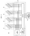
- FIG. 3 shows a block diagram of an exemplary system 300 with antenna sub-arrays 301-304, antenna controller 310, and MIMO communications equipment 320.
- Antenna sub-arrays 301-304 can be implemented, for example, as described above.
- MIMO communications equipment 320 can be a conventional wireless MIMO transceiver, transmitter or receiver (e.g., WiMAX, LTE).
- Antenna controller 310 has an antenna interface coupled to the antenna elements of sub-arrays 301-304, and a communications equipment interface coupled to MIMO communications equipment 320. As described in greater detail below, antenna controller 310 operates to selectively provide paths between a subset of the antenna elements in sub-arrays 301-304 and MIMO communications equipment 320.
- antenna controller 310 comprises signal analysis block 312, antenna element selection block 314, and switching block 316.
- Signal analysis block 312 monitors and analyzes the signals on the antenna elements in sub-arrays 301-304. Preferably, signal analysis block 312 monitors and analyzes the signals on at least one antenna element in each sub-array 301-304. In an exemplary embodiment, signal analysis block 312 evaluates the richness of the channel experienced by each sub-array 301-304 or possibly other combinations of elements. Such an evaluation can be performed, for example, using pilot tones or training sequences to estimate the channel matrix, channel rank, channel matrix eigenvalue spread, Rician K-factor, and/or specular component, among other possible parameters, in accordance with known techniques.
- antenna element selection block 314 selects those antenna elements which would provide the best performance for the current environment.
- the selected antenna elements may be in the same sub-array 301-304 or in different sub-arrays.
- switching block 316 Under the control of antenna element selection block 314, switching block 316 provides paths between the selected antenna elements and MIMO communications equipment 320.
- switching block 316 connects four out of sixteen possible antenna elements to MIMO communications equipment 320 based on control signals from selection block 314.
- Switching block 316 can be implemented, for example, using analog switches, relays or the like.
- the paths provided by switching block 316 between the selected antenna elements and MIMO communications equipment 320 allow both transmission and reception with the selected antenna elements.
- a channel rank or channel matrix eigenvalue spread is determined by signal analysis block 312 for each sub-array 301-304.
- the sub-array 301-304 with the highest channel rank or channel matrix eigenvalue spread is selected by antenna element selection block 314 for connection by switching block 316 to MIMO communications equipment 320.
- the antenna sub-array 301-304 with the greatest spread in channel matrix eigenvalues is selected by antenna controller 310 for connection to communications equipment 320.
- all four of the antenna elements of the selected sub-array are switched through to communications equipment 320 by switching block 316.
- the antenna elements of sub-array 103 on the left side of vehicle 200 would be selected and switched through to communications equipment 320 by antenna controller 310 .
- the antenna elements are evaluated and selected independently of their placement within a sub-array 301-304.
- the four antenna elements that would provide optimal performance for the current environment as determined by analysis block 312 and selection block 314, are switched through to communications equipment 320 by switching block 316.
- antenna controller 310 selects and switches sub-arrays of antenna elements, whereas in a second embodiment, antenna controller 310 selects and switches individual antenna elements independently of their placement within a sub-array.
- antenna controller 310 comprises a signal analysis block 312 that can receive and evaluate N signals, one from each of the N sub-arrays.
- antenna controller 310 comprises a signal analysis block 312 that can receive and evaluate N x m signals, one from each antenna element.
- the first embodiment may be preferred in terms of complexity and/or cost.
- the selected antenna elements are used for both transmitting and receiving. Such an embodiment is suitable for applications in which there is a good correlation between the transmit and receive channels. In a further exemplary embodiment, however, different antenna elements may be selected for transmitting and receiving. Such an embodiment is suitable for applications, such as those using frequency division duplex (FDD) to separate uplink from downlink, in which there may not be a good correlation between the transmit and receive channels.
- FDD frequency division duplex
- antenna sub-arrays for transmitting and receiving are selected independently.
- a pilot signal is transmitted from each sub-array so that the receiver (such as tower 210 in FIG. 2 ) can evaluate which is best.
- the receiver then feeds the results of the evaluation back to the vehicle 200 and antenna controller 310 for selection of the sub-array providing the best performance.
- the rate of the feedback should be commensurate with the rate of change of the channel, otherwise performance can be degraded.
- the sub-array selected for the receive channel can be used for the transmit channel.
- Antenna controller 310 preferably operates to evaluate, select and switch antenna elements at a rate commensurate with the rate of change of the channel (channel coherence time).
- channel coherence time In a typical environment with a vehicle travelling at 60 mph and a center frequency of 1900 MHz, the coherence time is approximately 6 ms and can vary between approximately 1 ms and 50 ms.
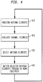
- FIG. 4 is a flowchart of an exemplary method of operation of an antenna controller, such as that of FIG. 3 , in accordance with the principles of the present disclosure.
- step 410 all or a subset of the antenna elements are monitored. In an exemplary embodiment, one element from each sub-array is monitored.
- channel richness is evaluated using, for example, pilot tones or training sequences to estimate the channel matrix, channel rank, channel matrix eigenvalue spread, Rician K-factor, and/or specular component, among other possible parameters.
- a subset of antenna elements is selected based on the evaluation performed at step 420.
- the selected antenna elements may be from the same antenna sub-array or from different sub-arrays.
- the selected antenna elements are switched through to the MIMO communications equipment coupled to the antenna controller.
- embodiments of the present disclosure allow the use of more antennas than would be possible with standard wireless equipment.
- the typical 4G solution chooses from at most four antennas
- an embodiment of the disclosure enables the use of substantially more than four antenna elements that can be distributed over multiple faces of the vehicle, each of which may be experiencing vastly different channel conditions. This results in improved performance over typical 4G solutions.
- embodiments of the invention can be used to enhance the performance of existing MIMO communications equipment.
Landscapes
- Engineering & Computer Science (AREA)
- Computer Security & Cryptography (AREA)
- Radar, Positioning & Navigation (AREA)
- Remote Sensing (AREA)
- Mobile Radio Communication Systems (AREA)
- Radio Transmission System (AREA)
Claims (14)
- Vorrichtung, die umfasst:eine Antennenanordnung (101 - 104, 301 - 304), wobei die Antennenanordnung (101 - 104, 301 - 304) eine Vielzahl von Antennenelementen (301.1 - 304.4) enthält, die in mindestens zwei Unter-Anordnungen (101, 102, 103, 104, 301, 302, 303, 304) angeordnet sind,undeine Antennen-Steuereinheit (310), wobei die Antennen-Steuereinheit (310) eine erste Schnittstelle, die mit der Vielzahl von Antennenelementen (301.1 - 304.4) verbunden ist, und eine zweite Schnittstelle aufweist, die zur Verbindung mit einer drahtlosen Multiple-Input-Multiple-Output (MIMO)-Kommunikationsvorrichtung (320) ausgebildet ist,dadurch gekennzeichnet, dassdie Antennen-Steuereinheit (310) ausgebildet ist zumAnalysieren einer Signalqualität von Signalen, die bei der Vielzahl von Antennenelementen in den Unter-Anordnungen empfangen werden,Auswählen einer Untermenge der Vielzahl von Antennenelementen (301.1 - 304.4), die von jeder der Unter-Anordnungen die beste Funkleistung liefern, zum Einschluss in die ausgewählte UntermengeundVerwenden der ersten und der zweiten Schnittstelle zur Bereitstellung eines Pfades zwischen der ausgewählten Untermenge von Antennenelementen und der drahtlosen MIMO-Kommunikationsvorrichtung.
- Vorrichtung von Anspruch 1, bei der die mindestens zwei Unter-Anordnungen (101, 102, 103, 104, 301, 302, 303, 304) an unterschiedlichen Flächen eines Fahrzeugs anbringbar sind.
- Vorrichtung von Anspruch 1, bei der die Antennen-Steuereinheit (310) die Untermenge von Antennenelementen entsprechend Bedingungen von drahtlosen Kommunikationskanälen bei den mindestens zwei Unter-Anordnungen (101, 102, 103, 104, 301, 302, 303, 304) auswählt.
- Vorrichtung von Anspruch 3, bei welcher die Antennen-Steuereinheit (310) die Kanal-Bedingungen entsprechend einer Einstufung und/oder der Eigenwert-Verteilung und/oder einem Rice-K-Faktor bewertet.
- Vorrichtung von Anspruch 3, bei der die ausgewählte Untermenge von Antennenelementen (301.1 - 304.4) in der gleichen Unter-Anordnung der mindestens zwei Unter-Anordnungen (101, 102, 103, 104, 301, 302, 303, 304) angeordnet sind.
- Vorrichtung von Anspruch 5, bei der die ausgewählte Untermenge von Antennenelementen (301.1 - 304.4) den größten Streubereich in Kanalmatrix-Eigenwerten der mindestens zwei Unter-Anordnungen (101, 102, 103, 104, 301, 302, 303, 304) aufweist.
- Vorrichtung von Anspruch 1, bei der die Antennen-Steuereinheit eine Untermenge von Antennenelementen (301.1 - 304.4) auswählt, bei der die größte Mehrwegausbreitung vorliegt.
- Vorrichtung von Anspruch 1, bei der mindestens ein Antennenelement der Vielzahl von Antennenelementen (301.1 - 304.4) als Applikation vorgesehen ist.
- Vorrichtung von Anspruch 8, bei der die Applikation im Wesentlichen optisch transparent ist.
- Vorrichtung von Anspruch 1, bei der jede Unter-Anordnung von mindestens zwei Unter-Anordnungen (101, 102, 103, 104, 301, 302, 303, 304) vier Antennenelemente (301.1 - 304.4) besitzt.
- Vorrichtung von Anspruch 1, bei der die Untermenge von Antennenelementen (301.1 - 304.4) vier Antennenelemente enthält.
- Verfahren bei einer Antennen-Steuereinheit zur Bereitstellung eines Pfades zwischen einer Vielzahl von Antennenelementen (301.1-304.4) und einem drahtlosen Multiple-Input-Multiple-Output (MIMO)-Kommunikationssystem (320), wobei die Vielzahl von Antennenelementen (301.1 - 304.4) in mindestens zwei Unter-Anordnungen (101, 102, 103, 104, 301, 302, 303, 304) angeordnet sind, wobei das Verfahren umfasst:Verbinden der Antennen-Steuereinheit (310) mit der Vielzahl von Antennenelementen (301.1 - 304.4) durch eine erste Schnittstelle und mit dem drahtlosen MIMO-Kommunikationssystem (320) durch eine zweite Schnittstelle,Analysieren einer Signalqualität von Signalen, die bei der Vielzahl von Antennenelementen in den Unter-Anordnungen empfangen werden,Auswählen einer Untermenge der Vielzahl von Antennenelementen (301.1 - 304.4), welche die beste Funkleistung liefern, wobei die Antennenelemente von jeder der Unter-Anordnungen zum Einschluss in die ausgewählte Untermenge ausgewählt werden,undVerwenden der ersten und der zweiten Schnittstelle zur Bereitstellung eines Pfades zwischen der ausgewählten Untermenge von Antennenelementen und dem drahtlosen MIMO-Kommunikationssystem (320).
- Verfahren von Anspruch 12, bei dem die Antennen-Steuereinheit (310) einen Pfad für die Untermenge von Antennenelementen entsprechend Bedingungen von drahtlosen Kommunikationskanälen bei den mindestens zwei Unter-Anordnungen (101, 102, 103, 104, 301, 302, 303, 304) bereitstellt,
wobei die Antennen-Steuereinheit (310) die Kanal-Bedingungen entsprechend einer Einstufung und/oder der Eigenwert-Verteilung und/oder einem Rice-K-Faktor bewerten kann. - Verfahren von Anspruch 12, bei dem die Antennen-Steuereinheit einen Pfad für eine Untermenge von Antennenelementen (301.1 - 304.4) bereitstellt, bei denen die größte Mehrwegausbreitung vorliegt.
Applications Claiming Priority (3)
| Application Number | Priority Date | Filing Date | Title |
|---|---|---|---|
| US22688609P | 2009-07-20 | 2009-07-20 | |
| US12/691,027 US20110012798A1 (en) | 2009-07-20 | 2010-01-21 | System and method for improving mimo performance of vehicular based wireless communications |
| PCT/US2010/042407 WO2011011307A1 (en) | 2009-07-20 | 2010-07-19 | System and method for improving mimo performance of vehicular based wireless communications |
Publications (3)
| Publication Number | Publication Date |
|---|---|
| EP2457286A1 EP2457286A1 (de) | 2012-05-30 |
| EP2457286A4 EP2457286A4 (de) | 2014-07-09 |
| EP2457286B1 true EP2457286B1 (de) | 2017-06-21 |
Family
ID=43464905
Family Applications (1)
| Application Number | Title | Priority Date | Filing Date |
|---|---|---|---|
| EP10802713.7A Active EP2457286B1 (de) | 2009-07-20 | 2010-07-19 | System und verfahren zur verbesserung der mimo-leistung von drahtlosen kommunikationen auf fahrzeugbasis |
Country Status (4)
| Country | Link |
|---|---|
| US (1) | US20110012798A1 (de) |
| EP (1) | EP2457286B1 (de) |
| CA (1) | CA2768645C (de) |
| WO (1) | WO2011011307A1 (de) |
Families Citing this family (21)
| Publication number | Priority date | Publication date | Assignee | Title |
|---|---|---|---|---|
| US11381285B1 (en) | 2004-08-02 | 2022-07-05 | Genghiscomm Holdings, LLC | Transmit pre-coding |
| ES2426321B1 (es) | 2011-09-16 | 2014-06-05 | Telefónica, S.A. | Método para implementar un modo de transmisión de múltiples entradas-múltiples salidas |
| WO2014091205A1 (en) * | 2012-12-14 | 2014-06-19 | Bae Systems Plc | Improvements in and relating to antennas |
| FR3008800B1 (fr) * | 2013-07-19 | 2015-07-17 | Thales Sa | Dispositif de detection de signaux electromagnetiques |
| CN105637773A (zh) * | 2013-08-14 | 2016-06-01 | 慧与发展有限责任合伙企业 | 发射天线选择 |
| DE102014200043A1 (de) * | 2014-01-07 | 2015-07-09 | Siemens Aktiengesellschaft | Empfangsvorrichtung zum Empfangen eines Nutzsignals |
| US12224860B1 (en) | 2014-01-30 | 2025-02-11 | Genghiscomm Holdings, LLC | Linear coding in decentralized networks |
| US9794983B2 (en) * | 2014-08-27 | 2017-10-17 | GM Global Technology Operations LLC | Embedded antenna system for a vehicle |
| WO2016195205A1 (ko) * | 2015-05-29 | 2016-12-08 | 엘지전자 주식회사 | 차량 간 통신 시스템에서 신호를 송수신하는 방법 및 장치 |
| WO2017025658A1 (en) * | 2015-08-13 | 2017-02-16 | Nokia Solutions And Networks Oy | Method and apparatus for implementing a cooperative multiple-input-multiple-output operation |
| TWI649909B (zh) * | 2016-01-19 | 2019-02-01 | 沈孟緯 | 一種二次電池 |
| CN108886391B (zh) * | 2016-04-29 | 2020-09-04 | 华为技术有限公司 | 用于视距天线阵列的方法和装置 |
| US10637705B1 (en) | 2017-05-25 | 2020-04-28 | Genghiscomm Holdings, LLC | Peak-to-average-power reduction for OFDM multiple access |
| US10243773B1 (en) * | 2017-06-30 | 2019-03-26 | Genghiscomm Holdings, LLC | Efficient peak-to-average-power reduction for OFDM and MIMO-OFDM |
| EP3432418B1 (de) * | 2017-07-18 | 2025-05-07 | Advanced Automotive Antennas, S.L. | Antennenmodule für fahrzeuge |
| US10880394B2 (en) * | 2018-03-04 | 2020-12-29 | Netskrt Systems, Inc. | Transparent cache system and method for transparently caching multimedia content from multiple content providers |
| KR102045483B1 (ko) * | 2018-05-21 | 2019-12-05 | 한양대학교 산학협력단 | 밀리미터 웨이브용 단말기 안테나 |
| US12206535B1 (en) | 2018-06-17 | 2025-01-21 | Tybalt, Llc | Artificial neural networks in wireless communication systems |
| US12580800B2 (en) | 2019-01-25 | 2026-03-17 | Tybalt, Llc | Orthogonal multiple access and non-orthogonal multiple access |
| CN113348593A (zh) * | 2019-02-02 | 2021-09-03 | 中兴通讯股份有限公司 | 全双工通信方法和装置 |
| US12184907B2 (en) | 2021-06-04 | 2024-12-31 | Netskrt Systems, Inc. | Method and apparatus for multicast control of a live video stream |
Family Cites Families (15)
| Publication number | Priority date | Publication date | Assignee | Title |
|---|---|---|---|---|
| CA1258705A (en) * | 1985-06-21 | 1989-08-22 | Hiroshi Kondo | Automobile antenna system |
| DE19806834A1 (de) * | 1997-03-22 | 1998-09-24 | Lindenmeier Heinz | Antennenanlage für den Hör- und Fernsehrundfunkempfang in Kraftfahrzeugen |
| GB2328819A (en) * | 1997-08-30 | 1999-03-03 | Ford Motor Co | Antenna cluster for vehicle collision warning system |
| US6662024B2 (en) * | 2001-05-16 | 2003-12-09 | Qualcomm Incorporated | Method and apparatus for allocating downlink resources in a multiple-input multiple-output (MIMO) communication system |
| ES2289151T3 (es) * | 2001-11-14 | 2008-02-01 | Quintel Technology Limited | Sistema de antena. |
| US6850741B2 (en) * | 2002-04-04 | 2005-02-01 | Agency For Science, Technology And Research | Method for selecting switched orthogonal beams for downlink diversity transmission |
| KR100604822B1 (ko) * | 2003-07-03 | 2006-07-28 | 삼성전자주식회사 | 서브-어레이 그루핑된 적응 배열 안테나들을 이용하여빔형성 및 다이버시티 이득을 제공하는 무선 페이딩 채널복조기, 이를 구비한 이동 통신 수신 시스템 및 그 방법 |
| KR101161873B1 (ko) * | 2004-09-07 | 2012-07-03 | 더 보드 오브 리전츠 오브 더 유니버시티 오브 텍사스 시스템 | 적응적 전송모드 전환 방식을 이용한 다중입출력 통신시스템 |
| US7400907B2 (en) * | 2005-08-29 | 2008-07-15 | Cisco Technology, Inc. | Method and system for partitioning an antenna array and applying multiple-input-multiple-output and beamforming mechanisms |
| DE102006039357B4 (de) * | 2005-09-12 | 2018-06-28 | Heinz Lindenmeier | Antennendiversityanlage zum Funkempfang für Fahrzeuge |
| US8095185B2 (en) * | 2006-06-09 | 2012-01-10 | Telefonaktiebolaget L M Ericsson (Publ) | Estimation of angular parameters of a signal at an antenna array |
| US7817100B2 (en) * | 2006-11-29 | 2010-10-19 | The Boeing Company | Ballistic resistant antenna assembly |
| WO2008110953A1 (en) * | 2007-03-15 | 2008-09-18 | Koninklijke Philips Electronics N.V. | Antenna array for vehicles |
| US8160601B2 (en) * | 2007-06-21 | 2012-04-17 | Elektrobit Wireless Communications Ltd. | Method for optimizing spatial modulation in a wireless link and network element thereto |
| WO2009157513A1 (ja) * | 2008-06-27 | 2009-12-30 | 京セラ株式会社 | 無線通信装置および無線通信方法 |
-
2010
- 2010-01-21 US US12/691,027 patent/US20110012798A1/en not_active Abandoned
- 2010-07-19 WO PCT/US2010/042407 patent/WO2011011307A1/en not_active Ceased
- 2010-07-19 CA CA2768645A patent/CA2768645C/en not_active Expired - Fee Related
- 2010-07-19 EP EP10802713.7A patent/EP2457286B1/de active Active
Also Published As
| Publication number | Publication date |
|---|---|
| US20110012798A1 (en) | 2011-01-20 |
| EP2457286A1 (de) | 2012-05-30 |
| EP2457286A4 (de) | 2014-07-09 |
| WO2011011307A1 (en) | 2011-01-27 |
| CA2768645A1 (en) | 2011-01-27 |
| CA2768645C (en) | 2015-09-08 |
Similar Documents
| Publication | Publication Date | Title |
|---|---|---|
| EP2457286B1 (de) | System und verfahren zur verbesserung der mimo-leistung von drahtlosen kommunikationen auf fahrzeugbasis | |
| KR101269823B1 (ko) | 분산식 기지국, 통신 시스템 및 신호 전송 방법 | |
| US7574236B1 (en) | System and method of operating an antenna in MIMO and beamforming modes | |
| KR102039535B1 (ko) | 무선 자원 할당 방법 및 장치 | |
| AU2013297246B2 (en) | Communication method and device using beamforming in wireless communication system | |
| EP3520226B1 (de) | System und verfahren zur hierarchischen strahlformung und rangadaption für eine hybride antennenarchitektur | |
| CN101222262B (zh) | 在认知无线电网络中检测未用频带的方法 | |
| EP3394990B1 (de) | Betrieb eines drahtlosen kommunikationssystems | |
| EP2206248B1 (de) | Drahtlose kommunikation mit bidirektionaler strahlformung sowie mehreren ein- und ausgängen | |
| KR101617232B1 (ko) | 무선 통신 시스템에서 안테나 제어 방법 및 장치 | |
| EP3282742B1 (de) | Mobilitätsverwaltung für hochschnelles mobiles benutzergerät | |
| CA2648568A1 (en) | Orthogonal resource reuse with sdma beams | |
| WO2007108885B1 (en) | Methods and apparatus for overlapping mimo antenna physical sectors | |
| JP2021534674A (ja) | データ伝送方法、端末及びネットワーク機器 | |
| CN103281108A (zh) | 车载智能天线 | |
| EP3244546B1 (de) | Basisbandvorrichtung mit mehreren eingängen und mehreren ausgängen (mimo) | |
| CN107534477A (zh) | 高速移动用户设备的信道状态信息报告 | |
| CN113067596B (zh) | 射频结构及电子设备 | |
| KR102751465B1 (ko) | 무선 통신 시스템에서 빔포밍을 수행하는 방법 및 이를 위한 장치 | |
| US11265065B2 (en) | System and method for MIMO wireless communication for a motor vehicle | |
| CN106209705A (zh) | 一种毫米波稀疏信道的主径估计方法及装置 | |
| KR20090043173A (ko) | 참조신호용 심볼 배치 방법, 서브 프레임 구조를 이용한신호 송신 방법 및 그 서브 프레임 구조 | |
| US20160064815A1 (en) | Antenna equipped with horizontally arranged radiating elements | |
| KR20180053202A (ko) | 무선 통신을 수행하는 차량 및 그의 통신 방법 | |
| CN113055030A (zh) | 探测参考信号传输电路、方法、装置、终端、基站、设备及介质 |
Legal Events
| Date | Code | Title | Description |
|---|---|---|---|
| PUAI | Public reference made under article 153(3) epc to a published international application that has entered the european phase |
Free format text: ORIGINAL CODE: 0009012 |
|
| 17P | Request for examination filed |
Effective date: 20120220 |
|
| AK | Designated contracting states |
Kind code of ref document: A1 Designated state(s): AL AT BE BG CH CY CZ DE DK EE ES FI FR GB GR HR HU IE IS IT LI LT LU LV MC MK MT NL NO PL PT RO SE SI SK SM TR |
|
| DAX | Request for extension of the european patent (deleted) | ||
| A4 | Supplementary search report drawn up and despatched |
Effective date: 20140606 |
|
| RIC1 | Information provided on ipc code assigned before grant |
Ipc: H01Q 1/32 20060101ALI20140602BHEP Ipc: H01Q 3/24 20060101ALI20140602BHEP Ipc: H01Q 3/40 20060101ALI20140602BHEP Ipc: H01Q 21/28 20060101ALI20140602BHEP Ipc: H01Q 25/00 20060101ALI20140602BHEP Ipc: H01Q 3/26 20060101ALI20140602BHEP Ipc: H01Q 1/38 20060101AFI20140602BHEP |
|
| GRAP | Despatch of communication of intention to grant a patent |
Free format text: ORIGINAL CODE: EPIDOSNIGR1 |
|
| STAA | Information on the status of an ep patent application or granted ep patent |
Free format text: STATUS: GRANT OF PATENT IS INTENDED |
|
| RIC1 | Information provided on ipc code assigned before grant |
Ipc: H01Q 1/32 20060101ALI20161220BHEP Ipc: H01Q 3/40 20060101ALI20161220BHEP Ipc: H01Q 3/24 20060101ALI20161220BHEP Ipc: H01Q 1/38 20060101AFI20161220BHEP Ipc: H01Q 21/28 20060101ALI20161220BHEP Ipc: H01Q 3/26 20060101ALI20161220BHEP Ipc: H01Q 25/00 20060101ALI20161220BHEP |
|
| INTG | Intention to grant announced |
Effective date: 20170113 |
|
| GRAS | Grant fee paid |
Free format text: ORIGINAL CODE: EPIDOSNIGR3 |
|
| GRAA | (expected) grant |
Free format text: ORIGINAL CODE: 0009210 |
|
| STAA | Information on the status of an ep patent application or granted ep patent |
Free format text: STATUS: THE PATENT HAS BEEN GRANTED |
|
| RAP1 | Party data changed (applicant data changed or rights of an application transferred) |
Owner name: TELCORDIA TECHNOLOGIES, INC. |
|
| AK | Designated contracting states |
Kind code of ref document: B1 Designated state(s): AL AT BE BG CH CY CZ DE DK EE ES FI FR GB GR HR HU IE IS IT LI LT LU LV MC MK MT NL NO PL PT RO SE SI SK SM TR |
|
| REG | Reference to a national code |
Ref country code: GB Ref legal event code: FG4D |
|
| REG | Reference to a national code |
Ref country code: CH Ref legal event code: EP |
|
| REG | Reference to a national code |
Ref country code: IE Ref legal event code: FG4D |
|
| REG | Reference to a national code |
Ref country code: AT Ref legal event code: REF Ref document number: 903710 Country of ref document: AT Kind code of ref document: T Effective date: 20170715 |
|
| REG | Reference to a national code |
Ref country code: FR Ref legal event code: PLFP Year of fee payment: 8 |
|
| REG | Reference to a national code |
Ref country code: DE Ref legal event code: R096 Ref document number: 602010043166 Country of ref document: DE |
|
| REG | Reference to a national code |
Ref country code: NL Ref legal event code: MP Effective date: 20170621 |
|
| PG25 | Lapsed in a contracting state [announced via postgrant information from national office to epo] |
Ref country code: NO Free format text: LAPSE BECAUSE OF FAILURE TO SUBMIT A TRANSLATION OF THE DESCRIPTION OR TO PAY THE FEE WITHIN THE PRESCRIBED TIME-LIMIT Effective date: 20170921 Ref country code: FI Free format text: LAPSE BECAUSE OF FAILURE TO SUBMIT A TRANSLATION OF THE DESCRIPTION OR TO PAY THE FEE WITHIN THE PRESCRIBED TIME-LIMIT Effective date: 20170621 Ref country code: LT Free format text: LAPSE BECAUSE OF FAILURE TO SUBMIT A TRANSLATION OF THE DESCRIPTION OR TO PAY THE FEE WITHIN THE PRESCRIBED TIME-LIMIT Effective date: 20170621 Ref country code: HR Free format text: LAPSE BECAUSE OF FAILURE TO SUBMIT A TRANSLATION OF THE DESCRIPTION OR TO PAY THE FEE WITHIN THE PRESCRIBED TIME-LIMIT Effective date: 20170621 Ref country code: GR Free format text: LAPSE BECAUSE OF FAILURE TO SUBMIT A TRANSLATION OF THE DESCRIPTION OR TO PAY THE FEE WITHIN THE PRESCRIBED TIME-LIMIT Effective date: 20170922 |
|
| REG | Reference to a national code |
Ref country code: LT Ref legal event code: MG4D |
|
| REG | Reference to a national code |
Ref country code: AT Ref legal event code: MK05 Ref document number: 903710 Country of ref document: AT Kind code of ref document: T Effective date: 20170621 |
|
| PG25 | Lapsed in a contracting state [announced via postgrant information from national office to epo] |
Ref country code: LV Free format text: LAPSE BECAUSE OF FAILURE TO SUBMIT A TRANSLATION OF THE DESCRIPTION OR TO PAY THE FEE WITHIN THE PRESCRIBED TIME-LIMIT Effective date: 20170621 Ref country code: NL Free format text: LAPSE BECAUSE OF FAILURE TO SUBMIT A TRANSLATION OF THE DESCRIPTION OR TO PAY THE FEE WITHIN THE PRESCRIBED TIME-LIMIT Effective date: 20170621 Ref country code: BG Free format text: LAPSE BECAUSE OF FAILURE TO SUBMIT A TRANSLATION OF THE DESCRIPTION OR TO PAY THE FEE WITHIN THE PRESCRIBED TIME-LIMIT Effective date: 20170921 Ref country code: SE Free format text: LAPSE BECAUSE OF FAILURE TO SUBMIT A TRANSLATION OF THE DESCRIPTION OR TO PAY THE FEE WITHIN THE PRESCRIBED TIME-LIMIT Effective date: 20170621 |
|
| PG25 | Lapsed in a contracting state [announced via postgrant information from national office to epo] |
Ref country code: RO Free format text: LAPSE BECAUSE OF FAILURE TO SUBMIT A TRANSLATION OF THE DESCRIPTION OR TO PAY THE FEE WITHIN THE PRESCRIBED TIME-LIMIT Effective date: 20170621 Ref country code: AT Free format text: LAPSE BECAUSE OF FAILURE TO SUBMIT A TRANSLATION OF THE DESCRIPTION OR TO PAY THE FEE WITHIN THE PRESCRIBED TIME-LIMIT Effective date: 20170621 Ref country code: EE Free format text: LAPSE BECAUSE OF FAILURE TO SUBMIT A TRANSLATION OF THE DESCRIPTION OR TO PAY THE FEE WITHIN THE PRESCRIBED TIME-LIMIT Effective date: 20170621 Ref country code: CZ Free format text: LAPSE BECAUSE OF FAILURE TO SUBMIT A TRANSLATION OF THE DESCRIPTION OR TO PAY THE FEE WITHIN THE PRESCRIBED TIME-LIMIT Effective date: 20170621 Ref country code: SK Free format text: LAPSE BECAUSE OF FAILURE TO SUBMIT A TRANSLATION OF THE DESCRIPTION OR TO PAY THE FEE WITHIN THE PRESCRIBED TIME-LIMIT Effective date: 20170621 |
|
| PG25 | Lapsed in a contracting state [announced via postgrant information from national office to epo] |
Ref country code: IS Free format text: LAPSE BECAUSE OF FAILURE TO SUBMIT A TRANSLATION OF THE DESCRIPTION OR TO PAY THE FEE WITHIN THE PRESCRIBED TIME-LIMIT Effective date: 20171021 Ref country code: SM Free format text: LAPSE BECAUSE OF FAILURE TO SUBMIT A TRANSLATION OF THE DESCRIPTION OR TO PAY THE FEE WITHIN THE PRESCRIBED TIME-LIMIT Effective date: 20170621 Ref country code: PL Free format text: LAPSE BECAUSE OF FAILURE TO SUBMIT A TRANSLATION OF THE DESCRIPTION OR TO PAY THE FEE WITHIN THE PRESCRIBED TIME-LIMIT Effective date: 20170621 Ref country code: ES Free format text: LAPSE BECAUSE OF FAILURE TO SUBMIT A TRANSLATION OF THE DESCRIPTION OR TO PAY THE FEE WITHIN THE PRESCRIBED TIME-LIMIT Effective date: 20170621 Ref country code: IT Free format text: LAPSE BECAUSE OF FAILURE TO SUBMIT A TRANSLATION OF THE DESCRIPTION OR TO PAY THE FEE WITHIN THE PRESCRIBED TIME-LIMIT Effective date: 20170621 |
|
| REG | Reference to a national code |
Ref country code: CH Ref legal event code: PL |
|
| REG | Reference to a national code |
Ref country code: DE Ref legal event code: R097 Ref document number: 602010043166 Country of ref document: DE |
|
| PG25 | Lapsed in a contracting state [announced via postgrant information from national office to epo] |
Ref country code: MC Free format text: LAPSE BECAUSE OF FAILURE TO SUBMIT A TRANSLATION OF THE DESCRIPTION OR TO PAY THE FEE WITHIN THE PRESCRIBED TIME-LIMIT Effective date: 20170621 |
|
| REG | Reference to a national code |
Ref country code: IE Ref legal event code: MM4A |
|
| PLBE | No opposition filed within time limit |
Free format text: ORIGINAL CODE: 0009261 |
|
| STAA | Information on the status of an ep patent application or granted ep patent |
Free format text: STATUS: NO OPPOSITION FILED WITHIN TIME LIMIT |
|
| PG25 | Lapsed in a contracting state [announced via postgrant information from national office to epo] |
Ref country code: IE Free format text: LAPSE BECAUSE OF NON-PAYMENT OF DUE FEES Effective date: 20170719 Ref country code: CH Free format text: LAPSE BECAUSE OF NON-PAYMENT OF DUE FEES Effective date: 20170731 Ref country code: DK Free format text: LAPSE BECAUSE OF FAILURE TO SUBMIT A TRANSLATION OF THE DESCRIPTION OR TO PAY THE FEE WITHIN THE PRESCRIBED TIME-LIMIT Effective date: 20170621 Ref country code: LI Free format text: LAPSE BECAUSE OF NON-PAYMENT OF DUE FEES Effective date: 20170731 |
|
| 26N | No opposition filed |
Effective date: 20180322 |
|
| REG | Reference to a national code |
Ref country code: BE Ref legal event code: MM Effective date: 20170731 |
|
| PG25 | Lapsed in a contracting state [announced via postgrant information from national office to epo] |
Ref country code: LU Free format text: LAPSE BECAUSE OF NON-PAYMENT OF DUE FEES Effective date: 20170719 |
|
| REG | Reference to a national code |
Ref country code: FR Ref legal event code: PLFP Year of fee payment: 9 |
|
| PG25 | Lapsed in a contracting state [announced via postgrant information from national office to epo] |
Ref country code: SI Free format text: LAPSE BECAUSE OF FAILURE TO SUBMIT A TRANSLATION OF THE DESCRIPTION OR TO PAY THE FEE WITHIN THE PRESCRIBED TIME-LIMIT Effective date: 20170621 Ref country code: BE Free format text: LAPSE BECAUSE OF NON-PAYMENT OF DUE FEES Effective date: 20170731 |
|
| PG25 | Lapsed in a contracting state [announced via postgrant information from national office to epo] |
Ref country code: MT Free format text: LAPSE BECAUSE OF NON-PAYMENT OF DUE FEES Effective date: 20170719 |
|
| PG25 | Lapsed in a contracting state [announced via postgrant information from national office to epo] |
Ref country code: HU Free format text: LAPSE BECAUSE OF FAILURE TO SUBMIT A TRANSLATION OF THE DESCRIPTION OR TO PAY THE FEE WITHIN THE PRESCRIBED TIME-LIMIT; INVALID AB INITIO Effective date: 20100719 |
|
| PG25 | Lapsed in a contracting state [announced via postgrant information from national office to epo] |
Ref country code: CY Free format text: LAPSE BECAUSE OF NON-PAYMENT OF DUE FEES Effective date: 20170621 |
|
| PG25 | Lapsed in a contracting state [announced via postgrant information from national office to epo] |
Ref country code: MK Free format text: LAPSE BECAUSE OF FAILURE TO SUBMIT A TRANSLATION OF THE DESCRIPTION OR TO PAY THE FEE WITHIN THE PRESCRIBED TIME-LIMIT Effective date: 20170621 |
|
| PG25 | Lapsed in a contracting state [announced via postgrant information from national office to epo] |
Ref country code: TR Free format text: LAPSE BECAUSE OF FAILURE TO SUBMIT A TRANSLATION OF THE DESCRIPTION OR TO PAY THE FEE WITHIN THE PRESCRIBED TIME-LIMIT Effective date: 20170621 |
|
| PG25 | Lapsed in a contracting state [announced via postgrant information from national office to epo] |
Ref country code: PT Free format text: LAPSE BECAUSE OF FAILURE TO SUBMIT A TRANSLATION OF THE DESCRIPTION OR TO PAY THE FEE WITHIN THE PRESCRIBED TIME-LIMIT Effective date: 20170621 |
|
| PG25 | Lapsed in a contracting state [announced via postgrant information from national office to epo] |
Ref country code: AL Free format text: LAPSE BECAUSE OF FAILURE TO SUBMIT A TRANSLATION OF THE DESCRIPTION OR TO PAY THE FEE WITHIN THE PRESCRIBED TIME-LIMIT Effective date: 20170621 |
|
| PGFP | Annual fee paid to national office [announced via postgrant information from national office to epo] |
Ref country code: DE Payment date: 20250729 Year of fee payment: 16 |
|
| PGFP | Annual fee paid to national office [announced via postgrant information from national office to epo] |
Ref country code: GB Payment date: 20250728 Year of fee payment: 16 |
|
| PGFP | Annual fee paid to national office [announced via postgrant information from national office to epo] |
Ref country code: FR Payment date: 20250725 Year of fee payment: 16 |