EP2456986B2 - Dispositif de commande d'un vérin pneumatique - Google Patents
Dispositif de commande d'un vérin pneumatique Download PDFInfo
- Publication number
- EP2456986B2 EP2456986B2 EP10740381.8A EP10740381A EP2456986B2 EP 2456986 B2 EP2456986 B2 EP 2456986B2 EP 10740381 A EP10740381 A EP 10740381A EP 2456986 B2 EP2456986 B2 EP 2456986B2
- Authority
- EP
- European Patent Office
- Prior art keywords
- cylinder
- shaft
- valve
- control device
- pressure
- Prior art date
- Legal status (The legal status is an assumption and is not a legal conclusion. Google has not performed a legal analysis and makes no representation as to the accuracy of the status listed.)
- Active
Links
Images

Classifications
-
- C—CHEMISTRY; METALLURGY
- C25—ELECTROLYTIC OR ELECTROPHORETIC PROCESSES; APPARATUS THEREFOR
- C25C—PROCESSES FOR THE ELECTROLYTIC PRODUCTION, RECOVERY OR REFINING OF METALS; APPARATUS THEREFOR
- C25C3/00—Electrolytic production, recovery or refining of metals by electrolysis of melts
- C25C3/06—Electrolytic production, recovery or refining of metals by electrolysis of melts of aluminium
- C25C3/14—Devices for feeding or crust breaking
-
- F—MECHANICAL ENGINEERING; LIGHTING; HEATING; WEAPONS; BLASTING
- F15—FLUID-PRESSURE ACTUATORS; HYDRAULICS OR PNEUMATICS IN GENERAL
- F15B—SYSTEMS ACTING BY MEANS OF FLUIDS IN GENERAL; FLUID-PRESSURE ACTUATORS, e.g. SERVOMOTORS; DETAILS OF FLUID-PRESSURE SYSTEMS, NOT OTHERWISE PROVIDED FOR
- F15B15/00—Fluid-actuated devices for displacing a member from one position to another; Gearing associated therewith
- F15B15/20—Other details, e.g. assembly with regulating devices
- F15B15/26—Locking mechanisms
- F15B15/261—Locking mechanisms using positive interengagement, e.g. balls and grooves, for locking in the end positions
Definitions
- the present invention relates to a system comprising a jack and a device for controlling the pneumatic jack.
- the context of the invention is that of pneumatic automatisms for the manufacturing industry and the process industries, in particular for aluminum smelters.
- the invention relates to a system comprising a device for controlling a jack and a jack and more particularly a system comprising a device for controlling a crusher breaking cylinder and the jack.
- crush-breakers are used in steel and aluminum plants to break the surface crust formed on the surface of a molten metal, the break crusher cylinder is then used to form a hole in this crust allowing incorporate additives.
- the forces used can be significant, depending on the thickness and stiffness of the crust formed, it is the same during the ascent of the cylinder to "unhook" the slag and residues glued to the chisel, which requires the use of a large cylinder. If the formed crust is less thick or more friable the maximum breaking stress, or cleaning, will not be reached. As a result, the maximum pressurization will not be necessary in this case and a lower pressure will allow a reduction in consumption and thus a significant source energy saving.
- AU 27128/84 describes such a control device using a 5/2 distributor, a pressure reduction valve and a 3/2 valve controlled directly by a programmable industrial controller.
- a sensor can detect the end of the thrust and inform the controller.
- the present invention aims in particular to provide a system comprising a control device of a jack and a cylinder for achieving energy savings, in particular by adapting the feed pressure to the effort just needed to break the crust and reassemble the cylinder by cleaning the chisel.
- a system according to the invention is defined in claim 1.
- the mechanical locking means may comprise a bolt adapted to cooperate with a stop means provided on a finger integral with the rod of the jack.
- the stop means may be a groove or a shoulder.
- the bolt may include an orifice in which can penetrate the finger.
- the probe can cooperate with an inclined surface provided on a trigger adapted to cooperate with the rod.
- the device is integrated in the cylinder body.
- the device can allow the adaptation of the supply pressure to the force just needed to break a resistance and reassemble the cylinder by breaking any friction forces of the application.
- the device may comprise means for detecting the low position of the rod by electrical contact between the chisel and the metal.
- the exhaust valve can include a flow limiter.
- the control device is schematically represented on the figure 1 .
- the cylinder 1 having a rod 2 integral with a piston 3.
- the cylinder has in the lower part an orifice 4 and in the upper part an orifice 5.
- the lower end of the rod 2 is integral with a chisel 6.
- the upper part of the piston 3 comprises a finger 7 provided with a groove 7a.
- the groove 7a is adapted to cooperate with the bolt 8a mu by the spring 15 of a locking device 8.
- the chisel is above the surface M of the molten metal.
- the surface M of the molten metal is electrically connected to the control part of a control device 10 via an automaton A.
- the control device also comprises a 5/2 type distributor 9.
- the pressure inlet of the distributor 9 feeds a valve 3/2 11, while the orifice 5 of the cylinder 1 is connected to the exhaust of the distributor 9.
- the pressure inlet feeds the orifice 5, the orifice 4 being exhausted.
- the valve 11 is shown in a position where the slide is in a position 11c allowing the outlet of the lower chamber of the cylinder 1 through the orifice 4
- the distributor 9, the locking device 8 and the valve 11 are controlled by the control device 10.
- the cylinder is then at rest in the high position.
- the steering device is shown Fig. 1 with its drawer in a position 10b where the pressure supply is blocked while the pipe to the locking device 8, the distributor 9 and the valve 11 is exhausted. In another position 10a, the pipe towards the locking device 8, the distributor 9 and the valve 11 is connected to the pressure inlet.
- valve 11 is controlled mechanically by means of a probe 11a.
- the control device 10 makes it possible to cause the slide of the valve 11 to be lowered, but the feeler 11a is able, in contact with the piston 3, to control the raising of the slide of the valve 11.
- a second step when the chisel 6 comes into contact with the molten aluminum M, the jack in contact with the aluminum behaves as an electrical contact.
- the cylinder 1 is made in such a way that there is electrical continuity between the chisel 6 and the rear bottom of the cylinder.
- a metal bearing not shown, is used and when the chisel 6 comes into contact with the aluminum M, an electrical signal can feed a controller A and cause the shutdown of the control device 10 and its passage in position 10b .
- the orifice 4 is then connected to the supply of the distributor 9 through the valve 11.
- the rod 2 and the chisel 6 then begin their ascent.
- the piston 3 causes the return of the probe 11a. Arriving at the top, during the rise, the piston 3 and the rod 7 slightly exceed the engagement of the bolt 8a to ensure the complete tilting of the valve 11 in the position 11 c. This change of state causes the atmosphere of the lower chamber of the breaker cylinder to be vented.
- control device can be integrated with the cylinder 1.
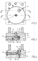
- Figures 2 to 5 illustrate an embodiment of the bottom of the cylinder 1, modified to accommodate the control device according to the invention.
- Fig. 3 can see the finger 7, slidably mounted in a housing 13 provided in the bottom of the cylinder 1, which has a thread in its upper part for fixing on the piston 3.
- the lower part of the finger 7 has a shoulder 7b which serves stop means.
- the bolt 8a is made in the form of a slide guided in translation, orthogonal to the direction of movement of the finger 7, in a second housing 14 provided in the bottom of the cylinder 1 and made in the form of a blind cylindrical orifice.
- a spring 15 is interposed between the wall of the housing 14 and the bolt 8a while the housing 14 is closed by a plug 16.
- the bolt 8a comprises an orifice 8b in which can penetrate the finger 7.
- the orifice 8b has an inner lip 8c adapted to cooperate with the shoulder 7b.
- valve 11 integrated in the bottom of the jack 1 can be seen.
- the slide 20 of the valve 11 and the probe 11a are slidably mounted in a recess provided in the bottom of the jack 1 and closed by a plug 21.
- the probe n ' is not here in direct contact with the piston 3.
- a trigger 12 is installed in a housing provided in the bottom of the cylinder 1 and closed by a plug 19 having an orifice allowing the passage of one end of the trigger 12.
- a spring 18 exerts a force on the trigger 12 tending to maintain the trigger 12 against the plug 19 so that the end of the trigger 12 slightly exceeds the plug 19.
- the displacement of the trigger is a translational movement along an axis parallel to the direction of movement of the piston 3.
- the trigger 12 comprises an inclined surface 12a adapted to cooperate with the rounded end of the probe 11a. In this way, when the piston 3 comes into contact with the end of the trigger 12 and causes the trigger 12 to enter its housing, the surface 12a exerts a force on the probe 11a which causes the displacement of the valve spool 20 11.
- This mechanism thus allows the detection of the arrival of the piston 3 in the high position and thus causes the change of state of the valve 11 and the depressurization of the inlet 4 of the piston 1.
- the exhaust cylinder 1 is oversized.
- the pressure inlet has a low flow rate so as to avoid a too high pressure rise in the drive chambers. In this way, full pressure can be reached in about 7 seconds. The maximum pressure is about 7 bars. Nevertheless, during the ascent and following the degree of soiling of the chisel, this pressure is often not necessary. Indeed, 1 bar is sufficient for the lift of the cylinder given the weight hitched to the rod. During the descent phase, the rise in pressure takes place only if the resistance of the crust requires it.
Landscapes
- Engineering & Computer Science (AREA)
- Chemical & Material Sciences (AREA)
- Chemical Kinetics & Catalysis (AREA)
- Mechanical Engineering (AREA)
- General Engineering & Computer Science (AREA)
- Fluid Mechanics (AREA)
- Physics & Mathematics (AREA)
- Electrochemistry (AREA)
- Materials Engineering (AREA)
- Metallurgy (AREA)
- Organic Chemistry (AREA)
- Percussive Tools And Related Accessories (AREA)
- Actuator (AREA)
- Preliminary Treatment Of Fibers (AREA)
Description
- La présente invention est relative à un système comportant un vérin et un dispositif de commande du vérin pneumatique.
- Le contexte de l'invention est celui des automatismes pneumatiques pour l'industrie manufacturière et les industries de procédés en particulier pour les alumineries.
- L'invention concerne un système comportant un dispositif de commande d'un vérin et un vérin et plus particulièrement système comportant un dispositif de commande d'un vérin briseur de croûte et le vérin. De tels vérins briseurs de croûte sont utilisés dans les installations sidérurgiques et alumineries afin de pouvoir briser la croûte superficielle se formant à la surface d'un métal en fusion, le vérin briseur de croûte est alors utilisé pour former un trou dans cette croûte permettant d'incorporer des additifs. Les efforts mis en oeuvre peuvent être importants, suivant l'épaisseur et la rigidité de la croute formée, il en est de même lors de la remontée du vérin pour « décrocher » les scories et résidus collés à la pointerolle, ce qui nécessite l'utilisation d'un vérin de grande taille. Si la croute formée est moins épaisse ou plus friable l'effort maximum de rupture, ou de nettoyage, ne sera pas atteint. En conséquence la mise en pression maximum ne sera, dans ce cas, pas nécessaire et une pression moindre permettra une diminution de consommation donc une économie d'énergie source importante.
- Les documents
EP1255049 etWO 2007/042780 décrivent un dispositif de commande d'un vérin. -
AU 27128/84 - Le maintien sous pression d'un tel vérin en permanence engendre donc une consommation très importante de ressources notamment en cas de fuites.
- La présente invention a pour but notamment de fournir un système comportant un dispositif de commande d'un vérin et un vérin permettant de réaliser une économie d'énergie, notamment par l'adaptation de la pression d'alimentation à l'effort juste nécessaire pour rompre la croute et remonter le vérin en nettoyant la pointerolle.
- Un système selon l'invention est défini à la revendication 1.
- Le moyen de verrouillage mécanique peut comprendre un pêne apte à coopérer avec un moyen d'arrêt prévu sur un doigt solidaire de la tige du vérin.
- Le moyen d'arrêt peut être une cannelure ou un épaulement.
- Le pêne peut comprendre un orifice dans lequel peut pénétrer le doigt.
- Le palpeur peut coopérer avec une surface inclinée prévue sur une gâchette apte à coopérer avec la tige.
- De manière plus avantageuse, le dispositif est intégré dans le corps du vérin.
- Le dispositif peut permettre l'adaptation de la pression d'alimentation à l'effort juste nécessaire pour rompre une résistance et remonter le vérin en rompant les éventuelles forces de frottement de l'application.
- Le dispositif peut comporter un moyen de détection de la position basse de la tige par contact électrique entre le pointerolle et le métal.
- L'échappement de la vanne peut comporter un limiteur de débit.
- D'autres caractéristiques et avantages de l'invention apparaîtront dans la description qui suit d'un mode de réalisation préféré avec référence aux dessins annexés mais qui n'a aucun caractère limitatif. Sur ces dessins :
-
Fig. 1 est un schéma des branchements des éléments d'un système selon l'invention. -
Fig. 2 est une vue de dessous du fond d'un vérin selon un mode de réalisation de l'invention. -
Fig. 3 est une coupe transversale selon la ligne III-III deFig. 2 illustrant un mode de réalisation du dispositif de verrouillage selon l'invention. -
Fig. 4 est une coupe transversale selon la ligne IV-IV deFig. 2 illustrant un mode de réalisation selon l'invention d'une vanne 3/2 et de son doigt de déclenchement mécanique, et -
Fig. 5 est une vue en perspective du fond de vérin deFig. 2 . - Dans toute la description qui suit d'un mode de réalisation d'un système selon l'invention, les termes relatifs tels que « supérieur », « inférieur », « avant », « arrière », « horizontal » et « vertical » sont à interpréter lorsque le vérin associé au dispositif D est installé verticalement, la pointerolle étant orientée vers le bas, en situation de fonctionnement.
- Le dispositif de commande est représenté schématiquement sur la
figure 1 . On peut voir le vérin 1 comportant une tige 2 solidaire d'un piston 3. Le vérin comporte en partie inférieure un orifice 4 et en partie supérieure un orifice 5. L'extrémité inférieure de la tige 2 est solidaire d'une pointerolle 6. La partie supérieure du piston 3 comporte un doigt 7 muni d'une cannelure 7a. La cannelure 7a est apte à coopérer avec le pêne 8a mu par le ressort 15 d'un dispositif de verrouillage 8. - La pointerolle se trouve au dessus de la surface M du métal en fusion. La surface M du métal en fusion est reliée électriquement à la partie commande d'un dispositif de pilotage 10 par l'intermédiaire d'un automate A.
- Le dispositif de commande comporte également un distributeur 9 de type 5/2. Dans la position représentée
figure 1 où le tiroir se trouve dans la position 9b, l'arrivée de pression du distributeur 9 alimente une vanne 3/2 11, tandis que l'orifice 5 du vérin 1 est relié à l'échappement du distributeur 9. Dans l'autre position 9a du distributeur 9, l'arrivée de pression alimente l'orifice 5, l'orifice 4 étant mis à l'échappement. - La vanne 11 est représentée dans une position où le tiroir se retrouve dans une position 11c permettant la mise à l'échappement de la chambre inférieure du vérin 1 par l'intermédiaire de l'orifice 4
- Le distributeur 9, le dispositif de verrouillage 8 ainsi que la vanne 11 sont commandés par le dispositif de pilotage 10. Le vérin est alors au repos en position haute.
- Le dispositif de pilotage est représenté
Fig. 1 avec son tiroir dans une position 10b où l'arrivée de pression est bloquée tandis que la conduite vers le dispositif de verrouillage 8, le distributeur 9 et la vanne 11 est mise à l'échappement. Dans une autre position 10a, la conduite vers le dispositif de verrouillage 8, le distributeur 9 et la vanne 11 est reliée à l'arrivée de pression. - Néanmoins, la vanne 11 est pilotée de manière mécanique par l'intermédiaire d'un palpeur 11a. En effet, le dispositif de pilotage 10 permet de provoquer la descente du tiroir de la vanne 11 mais le palpeur 11a est apte, au contact du piston 3, à commander la remontée du tiroir de la vanne 11.
- Sur
Fig.1 , le piston 3 est représenté en fin de course ascendante et de ce fait actionne le palpeur 11a provoquant le déplacement du tiroir de la vanne 11 vers la position 11 c. Dans la position 11c l'orifice 4 est relié à l'échappement de la vanne 11 et la pression en provenance du distributeur 9 est bloquée. - Le fonctionnement s'effectue de la manière qui suit.
- Dans la position repos, il n'y a pas de pression dans les chambres du vérin. La mise sous tension du dispositif de pilotage 10 et le passage de son tiroir en position 10a a pour conséquence :
- a) le déverrouillage du dispositif de verrouillage 8 par l'arrivée de pression et la compression du ressort 15 ; ici il faut remarquer que le dispositif est dimensionné de telle manière que ce déverrouillage soit prioritaire, les canaux d'acheminement intégrés dans le fond du vérin 1 sont donc dessinés spécialement afin de permettre ce fonctionnement prioritaire. Le déverrouillage provoque la descente de la tige 2 et de la pointerolle 6 sous l'action de leur propre poids ;
- b) le tiroir du distributeur 9 passe en position 9a ce qui permet la mise sous pression de la chambre supérieure du vérin 1 par l'intermédiaire de l'orifice 5. L'échappement du vérin 1 se fait à travers la vanne 11, dont le tiroir passe en position 11 b, reliée à l'atmosphère par le distributeur 9 ;
- c) la tige 2 et la pointerolle 6 poursuivent donc leur descente sous pression dans ce cas comme la chambre inférieure n'est soumise qu'à la pression atmosphérique, la pression dans la chambre supérieure est extrêmement faible.
- Dans un second temps, lorsque la pointerolle 6 vient au contact de l'aluminium M en fusion, le vérin au contact de l'aluminium se comporte comme un contact électrique. En effet, le vérin 1 est réalisé de telle manière qu'il y a continuité électrique entre la pointerolle 6 et le fond arrière du vérin. A cet effet, un palier métallique, non représenté, est utilisé et lorsque la pointerolle 6 arrive au contact de l'aluminium M, un signal électrique peut alimenter un automate A et provoquer la coupure du dispositif de pilotage 10 et son passage en position 10b.
- Ce passage en position 10b provoque le changement d'état du distributeur 9 en position 9b et la mise au repos du dispositif de verrouillage 8. Le dispositif de verrouillage 8 revient donc en position verrouillée où le pêne 8a est sorti sous l'action du ressort 15. La vanne 11 reste en position 11 b.
- L'orifice 4 est alors relié à l'alimentation du distributeur 9 à travers la vanne 11. La tige 2 et la pointerolle 6 entament ensuite leur remontée.
- Dans ce cas, comme la chambre supérieure du vérin n'est soumise qu'à une faible pression, la pression dans la chambre inférieure est faible. En fin de course supérieure, la partie supérieure du doigt 7 escamote le pêne 8a du fait de sa forme. Ceci permet la coopération du pêne 8a avec la cannelure 7a et le blocage de la tige du vérin.
- Par ailleurs, le piston 3 provoque la rentrée du palpeur 11a. En arrivant en haut, lors de la montée, le piston 3 et la tige 7 dépassent légèrement l'enclenchement du pêne 8a pour assurer le basculement complet de la vanne 11 dans la position 11 c. Ce changement d'état provoque la mise à l'atmosphère de la chambre inférieure du vérin briseur.
- Puis le piston 3 et la tige 7 effectuent une légère descente pour l'accrochage du pêne qui s'effectue sans choc car un limiteur de débit L prévu sur l'échappement évite une descente brutale du piston 3 jusqu'à la butée de la cannelure 7a contre le pêne.
- Le système est maintenant stable sans pression et prêt pour la prochaine manoeuvre.
- De manière avantageuse, le dispositif de commande peut être intégré au vérin 1. Les
figures 2 à 5 illustrent un mode de réalisation du fond du vérin 1, modifié pour accueillir le dispositif de commande selon l'invention. - Dans un tel cas, des modes de réalisation respectivement du dispositif de verrouillage 8 et de la vanne 9 sont illustrés
Fig 3 et 4 . -
Fig. 3 ont peut voir le doigt 7, monté coulissant dans un logement 13 prévu dans le fond du vérin 1, qui comporte un filetage dans sa partie supérieure permettant sa fixation sur le piston 3. La partie inférieure du doigt 7 comporte un épaulement 7b qui fait office de moyen d'arrêt. - Le pêne 8a est réalisé sous la forme d'un tiroir guidé en translation, orthogonalement à la direction de déplacement du doigt 7, dans un second logement 14 prévu dans le fond du vérin 1 et réalisé sous la forme d'un orifice cylindrique borgne.
- Un ressort 15 est interposé entre la paroi du logement 14 et le pêne 8a tandis que le logement 14 est fermé par un bouchon 16. Un pion 17, solidaire du bouchon 16 et monté coulissant dans le pêne 8a, empêche la rotation du pêne 8a.
- Le pêne 8a comprend un orifice 8b dans lequel peut pénétrer le doigt 7. L'orifice 8b présente une lèvre interne 8c apte à coopérer avec l'épaulement 7b.
-
Fig. 4 , on peut voir la vanne 11 intégrée dans le fond du vérin 1. Le tiroir 20 de la vanne 11 et le palpeur 11a sont montés coulissants dans un logement prévu dans le fond du vérin 1 et fermé par un bouchon 21. Le palpeur n'est pas ici en contact direct avec le piston 3. - Une gâchette 12 est installée dans un logement prévu dans le fond du vérin 1 et fermé par un bouchon 19 comportant un orifice permettant le passage d'une extrémité de la gâchette 12. Un ressort 18 exerce un effort sur la gâchette 12 tendant à maintenir la gâchette 12 contre le bouchon 19 de telle sorte que l'extrémité de la gâchette 12 dépasse légèrement du bouchon 19. Le déplacement de la gâchette est un mouvement de translation selon un axe parallèle à la direction de déplacement du piston 3.
- La gâchette 12 comprend une surface inclinée 12a apte à coopérer avec l'extrémité arrondie du palpeur 11a. De cette façon lorsque le piston 3 vient au contact de l'extrémité de la gâchette 12 et provoque la rentrée de la gâchette 12 dans son logement, la surface 12a exerce un effort sur le palpeur 11a qui provoque le déplacement du tiroir 20 de la vanne 11.
- Ce mécanisme permet donc la détection de l'arrivée du piston 3 en position haute et provoque ainsi le changement d'état de la vanne 11 et la mise hors pression de l'entrée 4 du piston 1.
- On constate donc l'intérêt de ce dispositif qui permet d'éviter que le système soit maintenu sous pression en dehors des phases de fonctionnement. De manière à éviter toute montée en pression, l'échappement du vérin 1 est surdimensionné. De la même façon, l'arrivée de pression comporte un faible débit de manière à éviter une montée de pression trop importante dans les chambres motrices. De cette façon, on peut atteindre la pleine pression en environ 7 s. La pression maximum est d'environ 7 bars. Néanmoins, lors de la remonté et suivant le degré de salissure de la pointerolle, cette pression n'est souvent pas nécessaire. En effet, 1 bar est suffisant pour la remontée du vérin compte tenu du poids attelé à la tige. En phase de descente, la montée en pression n'a lieu que si la résistance de la croute le nécessite.
Claims (9)
- Système comportant un vérin pneumatique briseur de croûte et un dispositif de commande pour le vérin pneumatique (1) briseur de croute comprenant un distributeur (9) et une vanne (11), le vérin (1) comportant une tige (2) solidaire d'un piston(3), le vérin étant destiné à être disposé verticalement, au dessus de la surface (M) d'un métal en fusion, la tige (2) du vérin (1) équipée d'une pointerolle (6) étant disposée face à la surface (M) du métal, caractérisé en ce que le dispositif de commande comprend un moyen de verrouillage mécanique (8) de la tige (2, 3, 7) du vérin permettant un maintien de la tige du vérin en position haute sans utilisation de l'énergie pneumatique, et en ce que la vanne (11) est pilotée de manière mécanique par l'intermédiaire d'un palpeur (11a) configuré pour être actionné par la remontée du piston du vérin, la vanne assurant la mise à la pression atmosphérique de la chambre inférieure du vérin (1) en position haute de la tige (2) à la fin de la course ascendante de la tige, reliant un orifice (4) de la chambre inférieure à un échappement de la vanne (11) et bloquant la pression en provenance du distributeur (9).
- Système selon la revendication 1, caractérisé en ce que le moyen de verrouillage mécanique (8) comprend un pêne (8a) apte à coopérer avec un moyen d'arrêt prévu sur un doigt (7) solidaire de la tige (2) du vérin.
- Système selon la revendication 2, caractérisé en ce que le moyen d'arrêt est une cannelure (7a) ou un épaulement.
- Système selon la revendication 2 ou 3, caractérisé en ce que le pêne (8a) comprend un orifice (8b) dans lequel peut pénétrer le doigt (7).
- Système selon la revendication 1, caractérisé en ce que le palpeur (11a) coopère avec une surface inclinée (12a) prévue sur une gâchette (12) apte à coopérer avec la tige (2).
- Système selon l'une quelconque des revendications précédentes, caractérisé en ce que le dispositif est intégré dans le corps du vérin (1).
- Système selon l'une quelconque des revendications précédentes, caractérisé en ce que le dispositif permet l'adaptation de la pression d'alimentation à l'effort juste nécessaire pour rompre une résistance et remonter le vérin (1) en rompant les éventuelles forces de frottement de l'application.
- Système selon l'une quelconque des revendications précédentes, caractérisé en ce qu'il comporte un moyen de détection de la position basse de la tige (2) par contact électrique entre le pointerolle (6) et le métal (M).
- Système selon l'une quelconque des revendications précédentes, caractérisé en ce que l'échappement de la vanne (11) comporte un limiteur de débit.
Applications Claiming Priority (2)
| Application Number | Priority Date | Filing Date | Title |
|---|---|---|---|
| FR0903581A FR2948426B1 (fr) | 2009-07-21 | 2009-07-21 | Dispositif de commande d'un verin pneumatique |
| PCT/IB2010/053276 WO2011010274A1 (fr) | 2009-07-21 | 2010-07-19 | Dispositif de commande d'un vérin pneumatique |
Publications (3)
| Publication Number | Publication Date |
|---|---|
| EP2456986A1 EP2456986A1 (fr) | 2012-05-30 |
| EP2456986B1 EP2456986B1 (fr) | 2014-02-26 |
| EP2456986B2 true EP2456986B2 (fr) | 2018-08-29 |
Family
ID=41693127
Family Applications (1)
| Application Number | Title | Priority Date | Filing Date |
|---|---|---|---|
| EP10740381.8A Active EP2456986B2 (fr) | 2009-07-21 | 2010-07-19 | Dispositif de commande d'un vérin pneumatique |
Country Status (8)
| Country | Link |
|---|---|
| EP (1) | EP2456986B2 (fr) |
| CN (2) | CN106835198B (fr) |
| AU (1) | AU2010274613B2 (fr) |
| CA (1) | CA2767588C (fr) |
| FR (1) | FR2948426B1 (fr) |
| IN (1) | IN2012DN00556A (fr) |
| WO (1) | WO2011010274A1 (fr) |
| ZA (1) | ZA201200414B (fr) |
Families Citing this family (29)
| Publication number | Priority date | Publication date | Assignee | Title |
|---|---|---|---|---|
| US8899264B2 (en) | 2011-12-15 | 2014-12-02 | Honeywell International Inc. | Gas valve with electronic proof of closure system |
| US9851103B2 (en) | 2011-12-15 | 2017-12-26 | Honeywell International Inc. | Gas valve with overpressure diagnostics |
| US9995486B2 (en) | 2011-12-15 | 2018-06-12 | Honeywell International Inc. | Gas valve with high/low gas pressure detection |
| US8839815B2 (en) | 2011-12-15 | 2014-09-23 | Honeywell International Inc. | Gas valve with electronic cycle counter |
| US9074770B2 (en) | 2011-12-15 | 2015-07-07 | Honeywell International Inc. | Gas valve with electronic valve proving system |
| US9557059B2 (en) | 2011-12-15 | 2017-01-31 | Honeywell International Inc | Gas valve with communication link |
| US8947242B2 (en) | 2011-12-15 | 2015-02-03 | Honeywell International Inc. | Gas valve with valve leakage test |
| US9846440B2 (en) | 2011-12-15 | 2017-12-19 | Honeywell International Inc. | Valve controller configured to estimate fuel comsumption |
| US8905063B2 (en) | 2011-12-15 | 2014-12-09 | Honeywell International Inc. | Gas valve with fuel rate monitor |
| US9835265B2 (en) | 2011-12-15 | 2017-12-05 | Honeywell International Inc. | Valve with actuator diagnostics |
| CN102618889A (zh) * | 2012-04-26 | 2012-08-01 | 山西兆丰铝业有限责任公司 | 铝电解槽打壳锤头 |
| US9234661B2 (en) | 2012-09-15 | 2016-01-12 | Honeywell International Inc. | Burner control system |
| US10422531B2 (en) | 2012-09-15 | 2019-09-24 | Honeywell International Inc. | System and approach for controlling a combustion chamber |
| CN102828202B (zh) * | 2012-09-17 | 2015-04-22 | 北京爱社时代科技发展有限公司 | 一种新型的智能打壳缸 |
| EP2868970B1 (fr) | 2013-10-29 | 2020-04-22 | Honeywell Technologies Sarl | Dispositif de régulation |
| US10024439B2 (en) | 2013-12-16 | 2018-07-17 | Honeywell International Inc. | Valve over-travel mechanism |
| CN103938226B (zh) * | 2014-04-18 | 2016-08-17 | 东北大学 | 一种多功能电解铝打壳气动控制系统 |
| CN104005057B (zh) * | 2014-04-29 | 2016-05-18 | 中国铝业股份有限公司 | 一种多功能联合机组打壳机自动锁定装置 |
| US9841122B2 (en) | 2014-09-09 | 2017-12-12 | Honeywell International Inc. | Gas valve with electronic valve proving system |
| US9645584B2 (en) | 2014-09-17 | 2017-05-09 | Honeywell International Inc. | Gas valve with electronic health monitoring |
| CN104674302B (zh) * | 2015-03-19 | 2017-01-04 | 河南理工大学 | 一种高强度电解铝打壳机导引板 |
| US10503181B2 (en) | 2016-01-13 | 2019-12-10 | Honeywell International Inc. | Pressure regulator |
| CN105736503B (zh) * | 2016-04-22 | 2017-07-07 | 济南弋泽展特机械有限公司 | 一种气路阀件 |
| US10564062B2 (en) | 2016-10-19 | 2020-02-18 | Honeywell International Inc. | Human-machine interface for gas valve |
| US11073281B2 (en) | 2017-12-29 | 2021-07-27 | Honeywell International Inc. | Closed-loop programming and control of a combustion appliance |
| US10697815B2 (en) | 2018-06-09 | 2020-06-30 | Honeywell International Inc. | System and methods for mitigating condensation in a sensor module |
| DE102019104283A1 (de) * | 2019-02-20 | 2020-08-20 | Saurer Technologies GmbH & Co. KG | Steuereinheit zur pneumatischen Ansteuerung eines aktiven Spulengatters |
| CN112498751B (zh) * | 2020-12-15 | 2024-06-25 | 航天科工火箭技术有限公司 | 一种连接解锁装置 |
| CN112760680B (zh) * | 2020-12-19 | 2024-02-02 | 内蒙古锦溪科技股份有限公司 | 一种可变行程打壳气缸 |
Citations (4)
| Publication number | Priority date | Publication date | Assignee | Title |
|---|---|---|---|---|
| US3359862A (en) † | 1966-02-25 | 1967-12-26 | Mcdowell Wellman Eng Co | Piston locking means |
| WO1981002044A1 (fr) † | 1980-01-04 | 1981-07-23 | Mecman Ab | Dispositif de verrouillage pour cylindres a fluide |
| WO2007042780A2 (fr) † | 2005-10-08 | 2007-04-19 | Norgren Limited | Ensemble actionneur |
| EP1820974A2 (fr) † | 2006-02-16 | 2007-08-22 | Ross Operating Valve Company | Moniteur d'entrée et loquet pour système de coupure de croûte |
Family Cites Families (15)
| Publication number | Priority date | Publication date | Assignee | Title |
|---|---|---|---|---|
| US4700612A (en) * | 1983-05-03 | 1987-10-20 | Swiss Aluminium Ltd. | Electropneumatic drive system for crust breaking devices and process for operating the same |
| EP0124480B1 (fr) | 1983-05-03 | 1987-10-28 | Schweizerische Aluminium Ag | Système de commande électropneumatique d'un dispositif pour concasser la croûte et procédé pour cette commande |
| US4524676A (en) * | 1984-01-19 | 1985-06-25 | American Standard Inc. | Hydraulic cylinder locking device |
| DE3809325A1 (de) * | 1988-03-19 | 1989-10-05 | Bosch Gmbh Robert | Tuerbetaetigungsvorrichtung |
| US5365828A (en) * | 1992-06-27 | 1994-11-22 | Deutsche Aerospace Ag | Pneumatic linear drive comprising a locking mechanism for end positions |
| WO1996002764A1 (fr) * | 1994-07-15 | 1996-02-01 | Terry Fluid Controls Pty. Ltd. | Actionneur |
| US6436270B1 (en) * | 1999-07-19 | 2002-08-20 | Ab Rexroth Mecman | Method and device for controlling the movement of a feeding and breaking chisel in an aluminum production cell |
| JP3930665B2 (ja) * | 1999-07-23 | 2007-06-13 | 株式会社コガネイ | 流体圧シリンダ |
| JP3559213B2 (ja) * | 2000-03-03 | 2004-08-25 | 株式会社半導体先端テクノロジーズ | ロードポート及びそれを用いた生産方式 |
| US6649035B2 (en) * | 2001-05-04 | 2003-11-18 | Ross Operating Valve Company | Low energy and non-heat transferring crust breaking system |
| CN2509362Y (zh) * | 2001-10-12 | 2002-09-04 | 济南华能气动元器件公司 | 带活塞杆自锁装置的气缸 |
| CN2584616Y (zh) * | 2002-12-16 | 2003-11-05 | 阜新市液压气动配套厂 | 耐高温、自润滑、机械防下落打壳气缸 |
| CN2739394Y (zh) * | 2004-06-30 | 2005-11-09 | 贵阳铝镁设计研究院 | 气缸自锁装置 |
| EP1987255B1 (fr) * | 2006-02-21 | 2012-06-06 | FESTO AG & Co. KG | Systeme pneumatique d'entrainement |
| CN101605927B (zh) * | 2007-02-07 | 2012-04-04 | 费斯托股份有限两合公司 | 用以捅破在金属熔液池上所形成的硬皮的硬皮破碎机 |
-
2009
- 2009-07-21 FR FR0903581A patent/FR2948426B1/fr active Active
-
2010
- 2010-07-19 CN CN201611078753.XA patent/CN106835198B/zh active Active
- 2010-07-19 WO PCT/IB2010/053276 patent/WO2011010274A1/fr not_active Ceased
- 2010-07-19 CN CN2010800328340A patent/CN102472302A/zh active Pending
- 2010-07-19 AU AU2010274613A patent/AU2010274613B2/en active Active
- 2010-07-19 IN IN556DEN2012 patent/IN2012DN00556A/en unknown
- 2010-07-19 EP EP10740381.8A patent/EP2456986B2/fr active Active
- 2010-07-19 CA CA2767588A patent/CA2767588C/fr active Active
-
2012
- 2012-01-18 ZA ZA2012/00414A patent/ZA201200414B/en unknown
Patent Citations (4)
| Publication number | Priority date | Publication date | Assignee | Title |
|---|---|---|---|---|
| US3359862A (en) † | 1966-02-25 | 1967-12-26 | Mcdowell Wellman Eng Co | Piston locking means |
| WO1981002044A1 (fr) † | 1980-01-04 | 1981-07-23 | Mecman Ab | Dispositif de verrouillage pour cylindres a fluide |
| WO2007042780A2 (fr) † | 2005-10-08 | 2007-04-19 | Norgren Limited | Ensemble actionneur |
| EP1820974A2 (fr) † | 2006-02-16 | 2007-08-22 | Ross Operating Valve Company | Moniteur d'entrée et loquet pour système de coupure de croûte |
Also Published As
| Publication number | Publication date |
|---|---|
| WO2011010274A1 (fr) | 2011-01-27 |
| CN106835198A (zh) | 2017-06-13 |
| AU2010274613A1 (en) | 2012-02-02 |
| FR2948426A1 (fr) | 2011-01-28 |
| ZA201200414B (en) | 2012-09-26 |
| EP2456986B1 (fr) | 2014-02-26 |
| FR2948426B1 (fr) | 2011-09-02 |
| AU2010274613B2 (en) | 2016-03-24 |
| IN2012DN00556A (fr) | 2015-06-12 |
| CN106835198B (zh) | 2021-01-15 |
| CA2767588A1 (fr) | 2011-01-27 |
| EP2456986A1 (fr) | 2012-05-30 |
| CA2767588C (fr) | 2017-12-05 |
| CN102472302A (zh) | 2012-05-23 |
Similar Documents
| Publication | Publication Date | Title |
|---|---|---|
| EP2456986B1 (fr) | Dispositif de commande d'un vérin pneumatique | |
| EP0122851B1 (fr) | Dispositif de sécurité à membrane et couteau d'éclatement, destiné à limiter la pression d'un fluide | |
| EP2414242B1 (fr) | Dispositif d'avitaillement de propulseurs d'un lanceur | |
| EP2255065B1 (fr) | Méthode d'installation de colonne sous-marine montante | |
| FR2966392A1 (fr) | Dispositif de verrouillage et de deverrouillage d'un bac de batterie de vehicule automobile electrique | |
| CA2604971C (fr) | Dispositif de controle de la course d'une pointerolle d'un systeme d'alimentation d'une cellule d'electrolyse de production d'aluminium | |
| EP1905724B1 (fr) | Dispositif de levage | |
| EP3921269B1 (fr) | Chariot à fourches embarquable sur un véhicule porteur | |
| EP2485260A3 (fr) | Procede d'assemblage et de fermeture hermetique d'un boitier d'encapsulation | |
| FR2530779A1 (fr) | Liaison de securite reliant un recipient contenant un gaz sous pression a un systeme d'evacuation | |
| EP2236680B1 (fr) | Chasse d'eau à ventouse magnétique et à double débit | |
| EP2585624A1 (fr) | Dispositif permettant d'extraire des cales de court-circuitage lors de la mise en circuit d'une cellule d'electrolyse pour la production d'aluminium | |
| EP3942194B1 (fr) | Suspension reglable pour un velo | |
| FR2978226A1 (fr) | Event de surpression pour un reservoir contenant une phase gazeuse et reservoir equipe dudit event | |
| EP2184392A1 (fr) | Dispositif de sécurité garantissant la fermeture d'un tambour de machine à laver | |
| FR2524173A1 (fr) | Systeme de remplissage d'un reservoir a liquide | |
| EP1312844B1 (fr) | Robinet pour réservoir ou conduit à gaz comportant un levier | |
| EP2872784B1 (fr) | Dispositif de commande du déplacement d'un vérin hydraulique, notamment pour machines hydrauliques | |
| FR2521462A1 (fr) | Dispositif d'amenee du metal dans les lingotieres de coulee continue | |
| EP1007247A1 (fr) | Procede et dispositif pour la coulee continue en charge des metaux | |
| EP0694367A1 (fr) | Machine de sablage à commande à distance | |
| FR3145610A1 (fr) | Dispositif de détermination du poids d’une charge installée sur le tablier d’un mât de levage à plusieurs éléments d’un chariot élévateur | |
| EP3743544A1 (fr) | Dispositif de perçage comprenant un fourreau tubulaire fixé à un vérin | |
| FR2982517A1 (fr) | Outil de montage pour positionner une rondelle sur une surface d'appui situee dans une zone d'acces difficile d'une piece | |
| FR2650361A2 (fr) | Clapet de vidange de citerne, notamment de citerne calorifugee |
Legal Events
| Date | Code | Title | Description |
|---|---|---|---|
| PUAI | Public reference made under article 153(3) epc to a published international application that has entered the european phase |
Free format text: ORIGINAL CODE: 0009012 |
|
| 17P | Request for examination filed |
Effective date: 20120119 |
|
| AK | Designated contracting states |
Kind code of ref document: A1 Designated state(s): AL AT BE BG CH CY CZ DE DK EE ES FI FR GB GR HR HU IE IS IT LI LT LU LV MC MK MT NL NO PL PT RO SE SI SK SM TR |
|
| DAX | Request for extension of the european patent (deleted) | ||
| GRAP | Despatch of communication of intention to grant a patent |
Free format text: ORIGINAL CODE: EPIDOSNIGR1 |
|
| INTG | Intention to grant announced |
Effective date: 20130705 |
|
| GRAP | Despatch of communication of intention to grant a patent |
Free format text: ORIGINAL CODE: EPIDOSNIGR1 |
|
| INTG | Intention to grant announced |
Effective date: 20131030 |
|
| GRAS | Grant fee paid |
Free format text: ORIGINAL CODE: EPIDOSNIGR3 |
|
| GRAA | (expected) grant |
Free format text: ORIGINAL CODE: 0009210 |
|
| AK | Designated contracting states |
Kind code of ref document: B1 Designated state(s): AL AT BE BG CH CY CZ DE DK EE ES FI FR GB GR HR HU IE IS IT LI LT LU LV MC MK MT NL NO PL PT RO SE SI SK SM TR |
|
| REG | Reference to a national code |
Ref country code: GB Ref legal event code: FG4D Free format text: NOT ENGLISH |
|
| REG | Reference to a national code |
Ref country code: CH Ref legal event code: EP |
|
| REG | Reference to a national code |
Ref country code: AT Ref legal event code: REF Ref document number: 653788 Country of ref document: AT Kind code of ref document: T Effective date: 20140315 |
|
| REG | Reference to a national code |
Ref country code: IE Ref legal event code: FG4D Free format text: LANGUAGE OF EP DOCUMENT: FRENCH |
|
| REG | Reference to a national code |
Ref country code: DE Ref legal event code: R096 Ref document number: 602010013771 Country of ref document: DE Effective date: 20140410 |
|
| REG | Reference to a national code |
Ref country code: NL Ref legal event code: VDEP Effective date: 20140226 |
|
| REG | Reference to a national code |
Ref country code: AT Ref legal event code: MK05 Ref document number: 653788 Country of ref document: AT Kind code of ref document: T Effective date: 20140226 |
|
| REG | Reference to a national code |
Ref country code: LT Ref legal event code: MG4D |
|
| PG25 | Lapsed in a contracting state [announced via postgrant information from national office to epo] |
Ref country code: NO Free format text: LAPSE BECAUSE OF FAILURE TO SUBMIT A TRANSLATION OF THE DESCRIPTION OR TO PAY THE FEE WITHIN THE PRESCRIBED TIME-LIMIT Effective date: 20140526 Ref country code: LT Free format text: LAPSE BECAUSE OF FAILURE TO SUBMIT A TRANSLATION OF THE DESCRIPTION OR TO PAY THE FEE WITHIN THE PRESCRIBED TIME-LIMIT Effective date: 20140226 Ref country code: IS Free format text: LAPSE BECAUSE OF FAILURE TO SUBMIT A TRANSLATION OF THE DESCRIPTION OR TO PAY THE FEE WITHIN THE PRESCRIBED TIME-LIMIT Effective date: 20140626 |
|
| PG25 | Lapsed in a contracting state [announced via postgrant information from national office to epo] |
Ref country code: CY Free format text: LAPSE BECAUSE OF FAILURE TO SUBMIT A TRANSLATION OF THE DESCRIPTION OR TO PAY THE FEE WITHIN THE PRESCRIBED TIME-LIMIT Effective date: 20140226 Ref country code: AT Free format text: LAPSE BECAUSE OF FAILURE TO SUBMIT A TRANSLATION OF THE DESCRIPTION OR TO PAY THE FEE WITHIN THE PRESCRIBED TIME-LIMIT Effective date: 20140226 Ref country code: SE Free format text: LAPSE BECAUSE OF FAILURE TO SUBMIT A TRANSLATION OF THE DESCRIPTION OR TO PAY THE FEE WITHIN THE PRESCRIBED TIME-LIMIT Effective date: 20140226 Ref country code: PT Free format text: LAPSE BECAUSE OF FAILURE TO SUBMIT A TRANSLATION OF THE DESCRIPTION OR TO PAY THE FEE WITHIN THE PRESCRIBED TIME-LIMIT Effective date: 20140626 Ref country code: FI Free format text: LAPSE BECAUSE OF FAILURE TO SUBMIT A TRANSLATION OF THE DESCRIPTION OR TO PAY THE FEE WITHIN THE PRESCRIBED TIME-LIMIT Effective date: 20140226 Ref country code: NL Free format text: LAPSE BECAUSE OF FAILURE TO SUBMIT A TRANSLATION OF THE DESCRIPTION OR TO PAY THE FEE WITHIN THE PRESCRIBED TIME-LIMIT Effective date: 20140226 |
|
| PG25 | Lapsed in a contracting state [announced via postgrant information from national office to epo] |
Ref country code: HR Free format text: LAPSE BECAUSE OF FAILURE TO SUBMIT A TRANSLATION OF THE DESCRIPTION OR TO PAY THE FEE WITHIN THE PRESCRIBED TIME-LIMIT Effective date: 20140226 Ref country code: LV Free format text: LAPSE BECAUSE OF FAILURE TO SUBMIT A TRANSLATION OF THE DESCRIPTION OR TO PAY THE FEE WITHIN THE PRESCRIBED TIME-LIMIT Effective date: 20140226 |
|
| PG25 | Lapsed in a contracting state [announced via postgrant information from national office to epo] |
Ref country code: EE Free format text: LAPSE BECAUSE OF FAILURE TO SUBMIT A TRANSLATION OF THE DESCRIPTION OR TO PAY THE FEE WITHIN THE PRESCRIBED TIME-LIMIT Effective date: 20140226 Ref country code: CZ Free format text: LAPSE BECAUSE OF FAILURE TO SUBMIT A TRANSLATION OF THE DESCRIPTION OR TO PAY THE FEE WITHIN THE PRESCRIBED TIME-LIMIT Effective date: 20140226 Ref country code: DK Free format text: LAPSE BECAUSE OF FAILURE TO SUBMIT A TRANSLATION OF THE DESCRIPTION OR TO PAY THE FEE WITHIN THE PRESCRIBED TIME-LIMIT Effective date: 20140226 Ref country code: RO Free format text: LAPSE BECAUSE OF FAILURE TO SUBMIT A TRANSLATION OF THE DESCRIPTION OR TO PAY THE FEE WITHIN THE PRESCRIBED TIME-LIMIT Effective date: 20140226 |
|
| REG | Reference to a national code |
Ref country code: DE Ref legal event code: R026 Ref document number: 602010013771 Country of ref document: DE |
|
| PG25 | Lapsed in a contracting state [announced via postgrant information from national office to epo] |
Ref country code: ES Free format text: LAPSE BECAUSE OF FAILURE TO SUBMIT A TRANSLATION OF THE DESCRIPTION OR TO PAY THE FEE WITHIN THE PRESCRIBED TIME-LIMIT Effective date: 20140226 Ref country code: SK Free format text: LAPSE BECAUSE OF FAILURE TO SUBMIT A TRANSLATION OF THE DESCRIPTION OR TO PAY THE FEE WITHIN THE PRESCRIBED TIME-LIMIT Effective date: 20140226 Ref country code: PL Free format text: LAPSE BECAUSE OF FAILURE TO SUBMIT A TRANSLATION OF THE DESCRIPTION OR TO PAY THE FEE WITHIN THE PRESCRIBED TIME-LIMIT Effective date: 20140226 |
|
| PLBI | Opposition filed |
Free format text: ORIGINAL CODE: 0009260 |
|
| 26 | Opposition filed |
Opponent name: PARKER HANNIFIN MANUFACTURING SWEDEN AB Effective date: 20141126 |
|
| PLAX | Notice of opposition and request to file observation + time limit sent |
Free format text: ORIGINAL CODE: EPIDOSNOBS2 |
|
| REG | Reference to a national code |
Ref country code: DE Ref legal event code: R119 Ref document number: 602010013771 Country of ref document: DE |
|
| REG | Reference to a national code |
Ref country code: DE Ref legal event code: R026 Ref document number: 602010013771 Country of ref document: DE Effective date: 20141126 |
|
| PG25 | Lapsed in a contracting state [announced via postgrant information from national office to epo] |
Ref country code: LU Free format text: LAPSE BECAUSE OF FAILURE TO SUBMIT A TRANSLATION OF THE DESCRIPTION OR TO PAY THE FEE WITHIN THE PRESCRIBED TIME-LIMIT Effective date: 20140719 |
|
| REG | Reference to a national code |
Ref country code: CH Ref legal event code: PL |
|
| GBPC | Gb: european patent ceased through non-payment of renewal fee |
Effective date: 20140719 |
|
| PG25 | Lapsed in a contracting state [announced via postgrant information from national office to epo] |
Ref country code: IT Free format text: LAPSE BECAUSE OF FAILURE TO SUBMIT A TRANSLATION OF THE DESCRIPTION OR TO PAY THE FEE WITHIN THE PRESCRIBED TIME-LIMIT Effective date: 20140226 |
|
| REG | Reference to a national code |
Ref country code: IE Ref legal event code: MM4A |
|
| REG | Reference to a national code |
Ref country code: DE Ref legal event code: R119 Ref document number: 602010013771 Country of ref document: DE Effective date: 20150203 |
|
| PG25 | Lapsed in a contracting state [announced via postgrant information from national office to epo] |
Ref country code: LI Free format text: LAPSE BECAUSE OF NON-PAYMENT OF DUE FEES Effective date: 20140731 Ref country code: CH Free format text: LAPSE BECAUSE OF NON-PAYMENT OF DUE FEES Effective date: 20140731 Ref country code: DE Free format text: LAPSE BECAUSE OF NON-PAYMENT OF DUE FEES Effective date: 20150203 |
|
| PLAF | Information modified related to communication of a notice of opposition and request to file observations + time limit |
Free format text: ORIGINAL CODE: EPIDOSCOBS2 |
|
| PG25 | Lapsed in a contracting state [announced via postgrant information from national office to epo] |
Ref country code: SI Free format text: LAPSE BECAUSE OF FAILURE TO SUBMIT A TRANSLATION OF THE DESCRIPTION OR TO PAY THE FEE WITHIN THE PRESCRIBED TIME-LIMIT Effective date: 20140226 Ref country code: GB Free format text: LAPSE BECAUSE OF NON-PAYMENT OF DUE FEES Effective date: 20140719 |
|
| PLBB | Reply of patent proprietor to notice(s) of opposition received |
Free format text: ORIGINAL CODE: EPIDOSNOBS3 |
|
| PG25 | Lapsed in a contracting state [announced via postgrant information from national office to epo] |
Ref country code: IE Free format text: LAPSE BECAUSE OF NON-PAYMENT OF DUE FEES Effective date: 20140719 |
|
| PG25 | Lapsed in a contracting state [announced via postgrant information from national office to epo] |
Ref country code: MC Free format text: LAPSE BECAUSE OF FAILURE TO SUBMIT A TRANSLATION OF THE DESCRIPTION OR TO PAY THE FEE WITHIN THE PRESCRIBED TIME-LIMIT Effective date: 20140226 Ref country code: SM Free format text: LAPSE BECAUSE OF FAILURE TO SUBMIT A TRANSLATION OF THE DESCRIPTION OR TO PAY THE FEE WITHIN THE PRESCRIBED TIME-LIMIT Effective date: 20140226 |
|
| PG25 | Lapsed in a contracting state [announced via postgrant information from national office to epo] |
Ref country code: BG Free format text: LAPSE BECAUSE OF FAILURE TO SUBMIT A TRANSLATION OF THE DESCRIPTION OR TO PAY THE FEE WITHIN THE PRESCRIBED TIME-LIMIT Effective date: 20140226 Ref country code: GR Free format text: LAPSE BECAUSE OF FAILURE TO SUBMIT A TRANSLATION OF THE DESCRIPTION OR TO PAY THE FEE WITHIN THE PRESCRIBED TIME-LIMIT Effective date: 20140527 Ref country code: MT Free format text: LAPSE BECAUSE OF FAILURE TO SUBMIT A TRANSLATION OF THE DESCRIPTION OR TO PAY THE FEE WITHIN THE PRESCRIBED TIME-LIMIT Effective date: 20140226 |
|
| REG | Reference to a national code |
Ref country code: FR Ref legal event code: PLFP Year of fee payment: 7 |
|
| PG25 | Lapsed in a contracting state [announced via postgrant information from national office to epo] |
Ref country code: HU Free format text: LAPSE BECAUSE OF FAILURE TO SUBMIT A TRANSLATION OF THE DESCRIPTION OR TO PAY THE FEE WITHIN THE PRESCRIBED TIME-LIMIT; INVALID AB INITIO Effective date: 20100719 Ref country code: BE Free format text: LAPSE BECAUSE OF FAILURE TO SUBMIT A TRANSLATION OF THE DESCRIPTION OR TO PAY THE FEE WITHIN THE PRESCRIBED TIME-LIMIT Effective date: 20140731 Ref country code: TR Free format text: LAPSE BECAUSE OF FAILURE TO SUBMIT A TRANSLATION OF THE DESCRIPTION OR TO PAY THE FEE WITHIN THE PRESCRIBED TIME-LIMIT Effective date: 20140226 |
|
| APBM | Appeal reference recorded |
Free format text: ORIGINAL CODE: EPIDOSNREFNO |
|
| APBP | Date of receipt of notice of appeal recorded |
Free format text: ORIGINAL CODE: EPIDOSNNOA2O |
|
| APAH | Appeal reference modified |
Free format text: ORIGINAL CODE: EPIDOSCREFNO |
|
| RAP2 | Party data changed (patent owner data changed or rights of a patent transferred) |
Owner name: ASCO SAS |
|
| REG | Reference to a national code |
Ref country code: FR Ref legal event code: PLFP Year of fee payment: 8 |
|
| APBU | Appeal procedure closed |
Free format text: ORIGINAL CODE: EPIDOSNNOA9O |
|
| APBW | Interlocutory revision of appeal recorded |
Free format text: ORIGINAL CODE: EPIDOSNIRAPO |
|
| APBE | Information on interlocutory revision deleted |
Free format text: ORIGINAL CODE: EPIDOSDIRAPO |
|
| PG25 | Lapsed in a contracting state [announced via postgrant information from national office to epo] |
Ref country code: MK Free format text: LAPSE BECAUSE OF FAILURE TO SUBMIT A TRANSLATION OF THE DESCRIPTION OR TO PAY THE FEE WITHIN THE PRESCRIBED TIME-LIMIT Effective date: 20140226 |
|
| REG | Reference to a national code |
Ref country code: FR Ref legal event code: PLFP Year of fee payment: 9 |
|
| PUAH | Patent maintained in amended form |
Free format text: ORIGINAL CODE: 0009272 |
|
| STAA | Information on the status of an ep patent application or granted ep patent |
Free format text: STATUS: PATENT MAINTAINED AS AMENDED |
|
| 27A | Patent maintained in amended form |
Effective date: 20180829 |
|
| AK | Designated contracting states |
Kind code of ref document: B2 Designated state(s): AL AT BE BG CH CY CZ DE DK EE ES FI FR GB GR HR HU IE IS IT LI LT LU LV MC MK MT NL NO PL PT RO SE SI SK SM TR |
|
| REG | Reference to a national code |
Ref country code: DE Ref legal event code: R102 Ref document number: 602010013771 Country of ref document: DE |
|
| PG25 | Lapsed in a contracting state [announced via postgrant information from national office to epo] |
Ref country code: AL Free format text: LAPSE BECAUSE OF FAILURE TO SUBMIT A TRANSLATION OF THE DESCRIPTION OR TO PAY THE FEE WITHIN THE PRESCRIBED TIME-LIMIT Effective date: 20140226 |
|
| P01 | Opt-out of the competence of the unified patent court (upc) registered |
Effective date: 20240503 |
|
| PGFP | Annual fee paid to national office [announced via postgrant information from national office to epo] |
Ref country code: FR Payment date: 20250620 Year of fee payment: 16 |