EP2456397B1 - Dispositif et procédé de production d un modèle de vibration - Google Patents
Dispositif et procédé de production d un modèle de vibration Download PDFInfo
- Publication number
- EP2456397B1 EP2456397B1 EP10736622.1A EP10736622A EP2456397B1 EP 2456397 B1 EP2456397 B1 EP 2456397B1 EP 10736622 A EP10736622 A EP 10736622A EP 2456397 B1 EP2456397 B1 EP 2456397B1
- Authority
- EP
- European Patent Office
- Prior art keywords
- mass
- sensor
- drive
- feedback
- person
- Prior art date
- Legal status (The legal status is an assumption and is not a legal conclusion. Google has not performed a legal analysis and makes no representation as to the accuracy of the status listed.)
- Active
Links
Images


Classifications
-
- A—HUMAN NECESSITIES
- A61—MEDICAL OR VETERINARY SCIENCE; HYGIENE
- A61F—FILTERS IMPLANTABLE INTO BLOOD VESSELS; PROSTHESES; DEVICES PROVIDING PATENCY TO, OR PREVENTING COLLAPSING OF, TUBULAR STRUCTURES OF THE BODY, e.g. STENTS; ORTHOPAEDIC, NURSING OR CONTRACEPTIVE DEVICES; FOMENTATION; TREATMENT OR PROTECTION OF EYES OR EARS; BANDAGES, DRESSINGS OR ABSORBENT PADS; FIRST-AID KITS
- A61F2/00—Filters implantable into blood vessels; Prostheses, i.e. artificial substitutes or replacements for parts of the body; Appliances for connecting them with the body; Devices providing patency to, or preventing collapsing of, tubular structures of the body, e.g. stents
- A61F2/50—Prostheses not implantable in the body
-
- A—HUMAN NECESSITIES
- A61—MEDICAL OR VETERINARY SCIENCE; HYGIENE
- A61B—DIAGNOSIS; SURGERY; IDENTIFICATION
- A61B34/00—Computer-aided surgery; Manipulators or robots specially adapted for use in surgery
- A61B34/70—Manipulators specially adapted for use in surgery
- A61B34/76—Manipulators having means for providing feel, e.g. force or tactile feedback
-
- A—HUMAN NECESSITIES
- A61—MEDICAL OR VETERINARY SCIENCE; HYGIENE
- A61F—FILTERS IMPLANTABLE INTO BLOOD VESSELS; PROSTHESES; DEVICES PROVIDING PATENCY TO, OR PREVENTING COLLAPSING OF, TUBULAR STRUCTURES OF THE BODY, e.g. STENTS; ORTHOPAEDIC, NURSING OR CONTRACEPTIVE DEVICES; FOMENTATION; TREATMENT OR PROTECTION OF EYES OR EARS; BANDAGES, DRESSINGS OR ABSORBENT PADS; FIRST-AID KITS
- A61F2/00—Filters implantable into blood vessels; Prostheses, i.e. artificial substitutes or replacements for parts of the body; Appliances for connecting them with the body; Devices providing patency to, or preventing collapsing of, tubular structures of the body, e.g. stents
- A61F2/50—Prostheses not implantable in the body
- A61F2/68—Operating or control means
- A61F2/70—Operating or control means electrical
-
- A—HUMAN NECESSITIES
- A61—MEDICAL OR VETERINARY SCIENCE; HYGIENE
- A61F—FILTERS IMPLANTABLE INTO BLOOD VESSELS; PROSTHESES; DEVICES PROVIDING PATENCY TO, OR PREVENTING COLLAPSING OF, TUBULAR STRUCTURES OF THE BODY, e.g. STENTS; ORTHOPAEDIC, NURSING OR CONTRACEPTIVE DEVICES; FOMENTATION; TREATMENT OR PROTECTION OF EYES OR EARS; BANDAGES, DRESSINGS OR ABSORBENT PADS; FIRST-AID KITS
- A61F2/00—Filters implantable into blood vessels; Prostheses, i.e. artificial substitutes or replacements for parts of the body; Appliances for connecting them with the body; Devices providing patency to, or preventing collapsing of, tubular structures of the body, e.g. stents
- A61F2/50—Prostheses not implantable in the body
- A61F2/68—Operating or control means
- A61F2002/6827—Feedback system for providing user sensation, e.g. by force, contact or position
-
- A—HUMAN NECESSITIES
- A61—MEDICAL OR VETERINARY SCIENCE; HYGIENE
- A61F—FILTERS IMPLANTABLE INTO BLOOD VESSELS; PROSTHESES; DEVICES PROVIDING PATENCY TO, OR PREVENTING COLLAPSING OF, TUBULAR STRUCTURES OF THE BODY, e.g. STENTS; ORTHOPAEDIC, NURSING OR CONTRACEPTIVE DEVICES; FOMENTATION; TREATMENT OR PROTECTION OF EYES OR EARS; BANDAGES, DRESSINGS OR ABSORBENT PADS; FIRST-AID KITS
- A61F2/00—Filters implantable into blood vessels; Prostheses, i.e. artificial substitutes or replacements for parts of the body; Appliances for connecting them with the body; Devices providing patency to, or preventing collapsing of, tubular structures of the body, e.g. stents
- A61F2/50—Prostheses not implantable in the body
- A61F2/76—Means for assembling, fitting or testing prostheses, e.g. for measuring or balancing, e.g. alignment means
- A61F2002/7615—Measuring means
Definitions
- the invention relates to a device and a method for generating a vibration pattern in a person with a drive which sets a mass in a rotational movement, and at least one sensor device which is coupled to a controller which controls the drive in dependence on sensor data of the sensor device.
- the US 5,413,611 describes a prosthesis with a feedback device.
- a feedback signal about the applied force of a driven prosthesis is generated via a vibration generator.
- the US 2002/0052663 A1 relates to a prosthetic device with a prosthetic knee joint and a vibration generator for generating a warning signal.
- the vibration generator may be formed as a wobble motor or wobble motor.
- the US 2004/0178989 A1 describes a system and method for providing haptic feedback in which a motor is set in motion with an eccentrically arranged mass to produce a vibration pattern.
- a similar device is in the WO 03/091984 A1 described.
- the object of the present invention is to provide an apparatus for generating a vibration pattern and a method in which complex feedback patterns can be easily generated. This is achieved by a device having the features of the main claim and by a method having the features of the independent claim. Advantageous embodiments and further developments of the invention are listed in the subclaims.
- the inventive device for generating a vibration pattern in a person with a drive which sets a mass in a rotational movement, and at least one sensor device which is coupled to a controller which controls the drive in dependence on sensor data of the sensor device provides that the Concentric mass is arranged homogeneously around its axis of rotation and that the device has an interface, the reaction forces of the mass due to the change in rotational motion occurs on the patient transfers.
- the device has a homogeneous concentric mass, which is offset by a drive in a rotary motion.
- the generation of the vibration pattern is based on the principle of action-reaction. By accelerating the rotating mass, a directional inertia force is generated which causes a stator about which the concentric mass rotates to counter-move. The resulting reaction force generates a noticeable feedback for the user.
- the rotating mass is formed as a rotor which is mounted around a stator of the drive, so that the device can be made very compact.
- the sensor device which supplies the data on the basis of which the control unit calculates how large the swept rotor angle, the angular velocity and the acceleration must be, can be designed as a pressure sensor, position sensor, moment sensor, motion sensor and / or temperature sensor. This makes it possible to absorb a multiplicity of influences and to transmit them to the user of the device by means of a vibration pattern.
- the sensor device like the vibration device, can be arranged in or on an exoprosthesis or coupled with an exophoresis.
- Alternative locations of the device are also available, in principle, all sufficiently sensitive body parts are suitable.
- a fastening arrangement for attaching the device to the person can be arranged on the device.
- the fastening arrangement may be formed as a belt, cuff or clasp.
- the vibration pattern is transmitted to the body via a coupling agent.
- the coupling agent can the Concentrate vibration, for example, by the stator via a boom or a device with a support surface, which is smaller than the stator, is coupled to the user of the device.
- the coupling element which transmits the reaction forces of the mass to the person, can be removably attached to the device or be an integral part of the device. If the coupling element is connected via a lever to a stator of the drive, a vibration transmission can be adjusted. It is also possible to make a gear ratio by means of a lever arrangement, via which an amplitude amplification is carried out.
- the method according to the invention for generating a feedback signal in which a sensor signal is provided via at least one sensor device and which is driven concentrically and homogeneously about a mass arranged in a rotation axis as a function of the sensor signal, provides that a frequency- and / or amplitude-modulated one Feedback pattern is generated.
- the mass is driven in different directions of rotation and at different angular speeds, depending on the sensor signal and corresponding feedback pattern to be generated.
- the mass for generating the feedback pattern is driven in response to the sensor signal in different acceleration patterns, wherein the acceleration pattern can be varied both in a frequency modulation and in an amplitude modulation.
- the amplitude modulation is regulated by the acceleration of the rotor.
- the regulation of the acceleration is carried out on the basis of measured movement variables of the rotor, the stronger the acceleration of the rotor, the higher the amplitude of the stimulation.
- the frequency is a function of the angular velocity and the swept rotor angle. By synchronizing the angular velocity with the swept rotor angles, it is possible to modulate the frequency of the stimulation in the desired manner.
- the frequency can be constant or variable.
- the signal is time-dependent or dependent on a state the device or its attachments is generated.
- the device can be triggered by certain conditions, for example the prosthesis. For example, by automatically switching the prosthesis to another mode, the information about another prosthesis behavior can be passed on to the prosthesis wearer by means of a corresponding signal. It is also possible to indicate certain states, for example a charge state of a rechargeable battery, an activated prosthesis state or an overheating of prosthesis components, by means of a corresponding vibration pattern.
- the device it is also possible to connect the device to a prosthesis via a cable or via a radio link. This makes it possible to transmit states that are determined within a prosthesis at a remote location via a vibration pattern.
- the application of the device is not limited to the transmission of data relating to a prosthesis. It is also possible to obtain feedback from training devices or feedback from myoelectric signals detected by corresponding arrester electrodes.
- FIG. 1 the basic structure of a device for generating a vibration pattern according to the present invention is shown.
- the swept rotor angle ⁇ or the angular velocity ⁇ are either measured directly via sensors or indirectly determined by a conversion of the rotor movement variables.
- the determined rotor position or angular velocity is used by the engine control unit (not shown) to generate predetermined vibration patterns based on sensor data provided by a sensor device that does not detect the rotor motions.
- FIG. 2 is in a perspective view of an embodiment, the rotating mass m given in the form of a ring which is arranged concentrically and homogeneously about the rotation axis 10 around.
- the axis of rotation 10 is located in the center of a stator 15, which is designed as a stator of a motor.
- the mass m is thus part of the drive, namely part of an electric motor.
- the drive is coupled via a gear or a translation with the rotatably mounted mass m.
- the movable rotor is rotating Mass m arranged so that here the design of the external rotor electric motor results.
- the rotating mass m may consist in the embodiment as an electronically commutated DC motor from annularly arranged permanent magnets or have this to generate the rotational movement of the rotating mass m.
- the rotating mass m may consist in the embodiment as an electronically commutated DC motor from annularly arranged permanent magnets or have this to generate the rotational movement of the rotating mass m.
- it allows the superposition of multiple modulated feedback patterns and thereby the generation of a large variation of highly complex feedback patterns, so that a variety of sensor data of various kinds can be easily and reliably transmitted to the user of the device 100 via a wide variety of feedback patterns.
- the amplitude modulation is controlled by the acceleration of the rotor m. If the rotating mass m is already in a rotary motion, the current state is detected by the engine control. On the basis of the measured or determined movement quantities of the rotating mass m, the regulation of the acceleration is then carried out so that the directional inertia force Fa, which can be transmitted via the stator 15 to the user of the device 100, is generated due to the change in the angular velocity.
- the stronger the acceleration of the rotating mass m ie both in terms of a positive and a negative acceleration, the higher the amplitude of the stimulation and the vibration amplitude. If the mass m initially stands still, the corresponding vibration effect is achieved by accelerating in one and / or other direction.
- the frequency of the generated vibration is a function of the angular velocity ⁇ and the swept rotor angle ⁇ .
- the frequency can either be constant or variable.
- the frequency of the stimulation results from the quotient of the angular velocity ⁇ to the swept rotor angle ⁇ .
- the device 100 is enlarged and shown schematically.
- the device 100 is arranged on the skin surface 30 of a user.
- the rotating mass m rotates about the rotation axis 10 around which the stator 15 is disposed.
- the device 100 provides in the illustrated embodiment that the mass m is part of the drive, namely the electric motor of stator 15 and the mass m forming rotor.
- the stator 15 of the motor generates a magnetic rotating field, due to which the rotating mass m is rotated in dependence on the type of rotating field.
- the stator 15 is fixed to a housing 20, which forms the interface between the device 100 and the skin surface 30.
- frequency and amplitude of the change a corresponding pattern of reaction forces and thus of vibrations is generated.
- the device 100 is shown in the applied state.
- the device 100 is attached to an upper arm via a fastener assembly 40 in the form of a cuff.
- the acting moments are shown.
- the reaction torque Mr is exerted by the rotating mass m on the interface, ie on the housing 20.
- the magnitude of the moment Mr is defined by the moment of inertia of the rotating, homogeneous concentric mass m and the force or acceleration acting thereon.
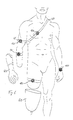
- FIG. 6 different locations of the device 100 are shown, for example, on the wrist, on the chest, on the upper arm, on the forearm or on the thigh. It is also possible to arrange the device directly in a prosthetic device 50, 60, for example in a forearm prosthesis 50 or in a thigh shaft 60 of a leg prosthesis.
- FIG. 7 shows a frequency modulation and an amplitude modulation.
- the positive and negative acceleration a means that either the direction of rotation is reversed or the mass m is accelerated and decelerated by a basic speed.
- an amplitude modulation is shown in which the measure of the acceleration a is varied without changing the frequency.
- this leads to the fact that first a weak vibration is transmitted to the user, which is increased with increasing time, until it then swells again after reaching the maximum.
- a prosthetic device 50, 60 for example, the current grip force
- other data can be forwarded via the device 100 to the user, for example, state data on temperature, power, operating modes, battery conditions or the like.
- myoelectric data which are recorded via lead electrodes, can be processed and passed on to the user as vibration signals, for example, in order to be able to carry out optimized training.
Landscapes
- Health & Medical Sciences (AREA)
- Engineering & Computer Science (AREA)
- Life Sciences & Earth Sciences (AREA)
- General Health & Medical Sciences (AREA)
- Animal Behavior & Ethology (AREA)
- Biomedical Technology (AREA)
- Heart & Thoracic Surgery (AREA)
- Veterinary Medicine (AREA)
- Public Health (AREA)
- Oral & Maxillofacial Surgery (AREA)
- Cardiology (AREA)
- Transplantation (AREA)
- Vascular Medicine (AREA)
- Surgery (AREA)
- Nuclear Medicine, Radiotherapy & Molecular Imaging (AREA)
- Robotics (AREA)
- Medical Informatics (AREA)
- Molecular Biology (AREA)
- Prostheses (AREA)
- User Interface Of Digital Computer (AREA)
- Rehabilitation Tools (AREA)
Claims (14)
- Dispositif de production d'un modèle de vibration sur une personne, comprenant un entraînement qui met une masse en mouvement de rotation, et comprenant un dispositif capteur couplé à une commande, laquelle pilote l'entraînement en fonction de données de capteur du dispositif capteur, caractérisé en ce que la masse (m) est disposée de façon concentrique et homogène autour de son axe de rotation (10), et en ce qu'une interface (20) transmet à la personne des forces de réaction de la masse (m) qui apparaissent en raison de la modification du mouvement de rotation.
- Dispositif selon la revendication 1, caractérisé en ce que l'entraînement est un moteur électrique.
- Dispositif selon la revendication 1 ou 2, caractérisé en ce que la masse rotative (m) est agencée en rotor qui est monté autour d'un stator (15) de l'entraînement.
- Dispositif selon l'une des revendications précédentes, caractérisé en ce que le dispositif capteur est réalisé sous forme de capteur de pression, capteur de position, capteur de moment, capteur de mouvement et/ou capteur de température.
- Dispositif selon l'une des revendications précédentes, caractérisé en ce que le dispositif capteur est agencé dans une exoprothèse (50, 60).
- Dispositif selon l'une des revendications précédentes, caractérisé en ce que le dispositif (100) est agencé dans ou sur une exoprothèse (50, 60) ou bien est couplé à l'exoprothèse (50, 60).
- Dispositif selon l'une des revendications précédentes, caractérisé en ce qu'il est prévu un agencement de fixation (40) pour installer le dispositif (100) sur la personne.
- Dispositif selon l'une des revendications précédentes, caractérisé en ce qu'il est prévu au moins un élément de couplage qui transmet les forces de réaction de la masse (m) à la personne.
- Dispositif selon la revendication 8, caractérisé en ce que l'élément de couplage est relié par un levier avec un stator (15) de l'entraînement.
- Procédé pour produire un signal de contre-réaction, dans lequel on tient à disposition un signal de capteur par l'intermédiaire d'au moins un dispositif capteur et on entraîne en fonction du signal de capteur une masse (m) disposée de façon concentrique et homogène autour d'un axe de rotation, pour produire par des forces de réaction de la masse (m) un modèle de contre-réaction modulé en fréquence et/ou en amplitude.
- Procédé selon la revendication 10, caractérisé en ce qu'on entraîne la masse dans des sens de rotation différents.
- Procédé selon la revendication 10 ou 11, caractérisé en ce que pour produire le signal de contre-réaction en fonction du signal de capteur on entraîne la masse dans différents modèles d'accélération.
- Procédé selon l'une des revendications 10 à 12, caractérisé en ce qu'on superpose les uns aux autres plusieurs modèles de contre-réaction.
- Procédé selon l'une des revendications 10 à 14, caractérisé en ce qu'on produit le signal de capteur en fonction du temps ou en fonction d'un état du dispositif ou de ses pièces annexes.
Applications Claiming Priority (2)
| Application Number | Priority Date | Filing Date | Title |
|---|---|---|---|
| DE102009034708A DE102009034708A1 (de) | 2009-07-24 | 2009-07-24 | Vorrichtung und ein Verfahren zur Erzeugung eines Vibrationsmusters |
| PCT/EP2010/004386 WO2011009576A1 (fr) | 2009-07-24 | 2010-07-19 | Dispositif et procédé de production dun modèle de vibration |
Publications (2)
| Publication Number | Publication Date |
|---|---|
| EP2456397A1 EP2456397A1 (fr) | 2012-05-30 |
| EP2456397B1 true EP2456397B1 (fr) | 2013-06-12 |
Family
ID=42937662
Family Applications (1)
| Application Number | Title | Priority Date | Filing Date |
|---|---|---|---|
| EP10736622.1A Active EP2456397B1 (fr) | 2009-07-24 | 2010-07-19 | Dispositif et procédé de production d un modèle de vibration |
Country Status (4)
| Country | Link |
|---|---|
| US (1) | US9827116B2 (fr) |
| EP (1) | EP2456397B1 (fr) |
| DE (1) | DE102009034708A1 (fr) |
| WO (1) | WO2011009576A1 (fr) |
Families Citing this family (2)
| Publication number | Priority date | Publication date | Assignee | Title |
|---|---|---|---|---|
| DE102009049465B4 (de) * | 2009-10-15 | 2015-11-26 | Molla-Ahmadi Nader | Verwendung einer Vibrationsmanschette zur optimierten Anpassung und Erleichterung der Anprobe von Prothesen |
| GB2598596B (en) * | 2020-09-03 | 2022-08-24 | Theia Guidance Systems Ltd | Mobility assistance device and method of providing mobility assistance |
Family Cites Families (13)
| Publication number | Priority date | Publication date | Assignee | Title |
|---|---|---|---|---|
| US5413611A (en) | 1992-07-21 | 1995-05-09 | Mcp Services, Inc. | Computerized electronic prosthesis apparatus and method |
| US6500210B1 (en) * | 1992-09-08 | 2002-12-31 | Seattle Systems, Inc. | System and method for providing a sense of feel in a prosthetic or sensory impaired limb |
| DE60131377T2 (de) | 2000-03-29 | 2008-09-04 | Massachusetts Institute Of Technology, Cambridge | Geschwindigkeitsangepasste und patientenangepasste knieprothese |
| US6504285B2 (en) * | 2001-02-08 | 2003-01-07 | Jae Shin Yun | Vector motor |
| US7161580B2 (en) | 2002-04-25 | 2007-01-09 | Immersion Corporation | Haptic feedback using rotary harmonic moving mass |
| AU2003286504A1 (en) | 2002-10-20 | 2004-05-13 | Immersion Corporation | System and method for providing rotational haptic feedback |
| WO2007021931A2 (fr) * | 2005-08-11 | 2007-02-22 | Rehabilitation Institute Of Chicago | Systeme et procede permettant d'ameliorer la fonctionnalite des protheses |
| US8398569B1 (en) * | 2006-04-14 | 2013-03-19 | Engineering Acoustics, Inc. | Apparatus for generating a vibrational stimulus using a rotating mass motor |
| CA2679633C (fr) * | 2007-02-06 | 2017-07-11 | Christopher C. Langenfeld | Prothese de bras |
| US20080200994A1 (en) * | 2007-02-21 | 2008-08-21 | Colgate J Edward | Detector and Stimulator for Feedback in a Prosthesis |
| US8469908B2 (en) * | 2007-04-06 | 2013-06-25 | Wilson T. Asfora | Analgesic implant device and system |
| US8475172B2 (en) * | 2007-07-19 | 2013-07-02 | Massachusetts Institute Of Technology | Motor learning and rehabilitation using tactile feedback |
| US8040223B2 (en) * | 2007-11-21 | 2011-10-18 | Engineering Acoustics, Inc. | Device and method for enhancing sensory perception of vibrational stimuli |
-
2009
- 2009-07-24 DE DE102009034708A patent/DE102009034708A1/de not_active Withdrawn
-
2010
- 2010-07-19 US US13/386,727 patent/US9827116B2/en not_active Expired - Fee Related
- 2010-07-19 WO PCT/EP2010/004386 patent/WO2011009576A1/fr not_active Ceased
- 2010-07-19 EP EP10736622.1A patent/EP2456397B1/fr active Active
Also Published As
| Publication number | Publication date |
|---|---|
| US9827116B2 (en) | 2017-11-28 |
| DE102009034708A1 (de) | 2011-01-27 |
| US20120119891A1 (en) | 2012-05-17 |
| EP2456397A1 (fr) | 2012-05-30 |
| WO2011009576A1 (fr) | 2011-01-27 |
Similar Documents
| Publication | Publication Date | Title |
|---|---|---|
| EP3490664B1 (fr) | Appareil orthopédique | |
| EP2528549B1 (fr) | Dispositif de déplacement et procédé pour le fonctionnement d'un dispositif de déplacement | |
| DE19638695B4 (de) | Modularer Schwingungskraftgenerator und Verfahren zu dessen Betrieb | |
| EP2791423B1 (fr) | Dispositif permettant de détecter le mouvement du rouleau d'un compacteur de sol | |
| EP2160168B1 (fr) | Procédé et dispositif d'entraînement et/ou d'analyse de l'appareil moteur d'un utilisateur | |
| WO2016120110A1 (fr) | Système de téléopération à retour de force haptique intrinsèque par adaptation dynamique des caractéristiques de la force de préhension et des coordonnées de l'effecteur terminal | |
| dos Santos et al. | Impedance control of a rotary series elastic actuator for knee rehabilitation | |
| DE2219155A1 (de) | Stellsystem | |
| EP2456397B1 (fr) | Dispositif et procédé de production d un modèle de vibration | |
| CN106389073A (zh) | 外骨骼机械装置 | |
| EP3911282A1 (fr) | Procédé pour la commande d'un dispositif orthétique ou prothétique et dispositif orthétique ou prothétique | |
| EP3727211B1 (fr) | Système d'au moins un composant orthopédique et un dispositif de fonctionnement et / ou de rétroaction | |
| DE102012213365A1 (de) | Piezo-angetriebenes Exoskelett | |
| DE102015110852B3 (de) | Gelenkverbindung mit einer Antriebseinrichtung sowie Verfahren zur Ansteuerung einer Schwenkbewegung einer Gelenkverbindung | |
| EP2392413B1 (fr) | Marteaux à vibration | |
| DE102013217184B4 (de) | Betätigungseinrichtung | |
| EP3934816B1 (fr) | Générateur de vibrations ainsi qu'engin de chantier comportant un tel générateur de vibrations | |
| EP2067533A1 (fr) | Vibrateur pour un appareil de fonçage vibratoire | |
| WO2021259986A1 (fr) | Ensemble prothèse comprenant une main prothétique et procédé pour faire fonctionner un ensemble prothèse | |
| EP4312896B1 (fr) | Système d'emboîture de prothèse et son procédé de fabrication | |
| WO2020083696A1 (fr) | Articulation technique orthopédique et mécanisme orthopédique | |
| CH703610B1 (de) | Modulares Trainingssystem zur Rehabilitation von physiologisch beeinträchtigten Patienten. | |
| WO2004019834A1 (fr) | Dispositif destine a influencer un mouvement au moyen d'un mecanisme parallele | |
| AT522226B1 (de) | Fremdkraftbetriebene Bewegungseinheit | |
| DE10308210A1 (de) | Trainingsgerät sowie Verfahren zum Betreiben eines Trainingsgerätes |
Legal Events
| Date | Code | Title | Description |
|---|---|---|---|
| PUAI | Public reference made under article 153(3) epc to a published international application that has entered the european phase |
Free format text: ORIGINAL CODE: 0009012 |
|
| 17P | Request for examination filed |
Effective date: 20120118 |
|
| AK | Designated contracting states |
Kind code of ref document: A1 Designated state(s): AL AT BE BG CH CY CZ DE DK EE ES FI FR GB GR HR HU IE IS IT LI LT LU LV MC MK MT NL NO PL PT RO SE SI SK SM TR |
|
| DAX | Request for extension of the european patent (deleted) | ||
| GRAP | Despatch of communication of intention to grant a patent |
Free format text: ORIGINAL CODE: EPIDOSNIGR1 |
|
| GRAS | Grant fee paid |
Free format text: ORIGINAL CODE: EPIDOSNIGR3 |
|
| GRAA | (expected) grant |
Free format text: ORIGINAL CODE: 0009210 |
|
| AK | Designated contracting states |
Kind code of ref document: B1 Designated state(s): AL AT BE BG CH CY CZ DE DK EE ES FI FR GB GR HR HU IE IS IT LI LT LU LV MC MK MT NL NO PL PT RO SE SI SK SM TR |
|
| REG | Reference to a national code |
Ref country code: GB Ref legal event code: FG4D Free format text: NOT ENGLISH |
|
| REG | Reference to a national code |
Ref country code: CH Ref legal event code: EP |
|
| REG | Reference to a national code |
Ref country code: AT Ref legal event code: REF Ref document number: 616379 Country of ref document: AT Kind code of ref document: T Effective date: 20130615 |
|
| REG | Reference to a national code |
Ref country code: IE Ref legal event code: FG4D Free format text: LANGUAGE OF EP DOCUMENT: GERMAN |
|
| REG | Reference to a national code |
Ref country code: DE Ref legal event code: R096 Ref document number: 502010003668 Country of ref document: DE Effective date: 20130808 |
|
| REG | Reference to a national code |
Ref country code: SE Ref legal event code: TRGR |
|
| REG | Reference to a national code |
Ref country code: NL Ref legal event code: T3 |
|
| PG25 | Lapsed in a contracting state [announced via postgrant information from national office to epo] |
Ref country code: GR Free format text: LAPSE BECAUSE OF FAILURE TO SUBMIT A TRANSLATION OF THE DESCRIPTION OR TO PAY THE FEE WITHIN THE PRESCRIBED TIME-LIMIT Effective date: 20130913 Ref country code: NO Free format text: LAPSE BECAUSE OF FAILURE TO SUBMIT A TRANSLATION OF THE DESCRIPTION OR TO PAY THE FEE WITHIN THE PRESCRIBED TIME-LIMIT Effective date: 20130912 Ref country code: FI Free format text: LAPSE BECAUSE OF FAILURE TO SUBMIT A TRANSLATION OF THE DESCRIPTION OR TO PAY THE FEE WITHIN THE PRESCRIBED TIME-LIMIT Effective date: 20130612 Ref country code: LT Free format text: LAPSE BECAUSE OF FAILURE TO SUBMIT A TRANSLATION OF THE DESCRIPTION OR TO PAY THE FEE WITHIN THE PRESCRIBED TIME-LIMIT Effective date: 20130612 Ref country code: SI Free format text: LAPSE BECAUSE OF FAILURE TO SUBMIT A TRANSLATION OF THE DESCRIPTION OR TO PAY THE FEE WITHIN THE PRESCRIBED TIME-LIMIT Effective date: 20130612 Ref country code: ES Free format text: LAPSE BECAUSE OF FAILURE TO SUBMIT A TRANSLATION OF THE DESCRIPTION OR TO PAY THE FEE WITHIN THE PRESCRIBED TIME-LIMIT Effective date: 20130923 |
|
| REG | Reference to a national code |
Ref country code: LT Ref legal event code: MG4D |
|
| PG25 | Lapsed in a contracting state [announced via postgrant information from national office to epo] |
Ref country code: HR Free format text: LAPSE BECAUSE OF FAILURE TO SUBMIT A TRANSLATION OF THE DESCRIPTION OR TO PAY THE FEE WITHIN THE PRESCRIBED TIME-LIMIT Effective date: 20130612 Ref country code: BG Free format text: LAPSE BECAUSE OF FAILURE TO SUBMIT A TRANSLATION OF THE DESCRIPTION OR TO PAY THE FEE WITHIN THE PRESCRIBED TIME-LIMIT Effective date: 20130912 |
|
| PG25 | Lapsed in a contracting state [announced via postgrant information from national office to epo] |
Ref country code: LV Free format text: LAPSE BECAUSE OF FAILURE TO SUBMIT A TRANSLATION OF THE DESCRIPTION OR TO PAY THE FEE WITHIN THE PRESCRIBED TIME-LIMIT Effective date: 20130612 |
|
| BERE | Be: lapsed |
Owner name: OTTO BOCK HEALTHCARE PRODUCTS GMBH Effective date: 20130731 |
|
| PG25 | Lapsed in a contracting state [announced via postgrant information from national office to epo] |
Ref country code: EE Free format text: LAPSE BECAUSE OF FAILURE TO SUBMIT A TRANSLATION OF THE DESCRIPTION OR TO PAY THE FEE WITHIN THE PRESCRIBED TIME-LIMIT Effective date: 20130612 Ref country code: IS Free format text: LAPSE BECAUSE OF FAILURE TO SUBMIT A TRANSLATION OF THE DESCRIPTION OR TO PAY THE FEE WITHIN THE PRESCRIBED TIME-LIMIT Effective date: 20131012 Ref country code: PT Free format text: LAPSE BECAUSE OF FAILURE TO SUBMIT A TRANSLATION OF THE DESCRIPTION OR TO PAY THE FEE WITHIN THE PRESCRIBED TIME-LIMIT Effective date: 20131014 Ref country code: SK Free format text: LAPSE BECAUSE OF FAILURE TO SUBMIT A TRANSLATION OF THE DESCRIPTION OR TO PAY THE FEE WITHIN THE PRESCRIBED TIME-LIMIT Effective date: 20130612 Ref country code: CZ Free format text: LAPSE BECAUSE OF FAILURE TO SUBMIT A TRANSLATION OF THE DESCRIPTION OR TO PAY THE FEE WITHIN THE PRESCRIBED TIME-LIMIT Effective date: 20130612 |
|
| PG25 | Lapsed in a contracting state [announced via postgrant information from national office to epo] |
Ref country code: PL Free format text: LAPSE BECAUSE OF FAILURE TO SUBMIT A TRANSLATION OF THE DESCRIPTION OR TO PAY THE FEE WITHIN THE PRESCRIBED TIME-LIMIT Effective date: 20130612 Ref country code: RO Free format text: LAPSE BECAUSE OF FAILURE TO SUBMIT A TRANSLATION OF THE DESCRIPTION OR TO PAY THE FEE WITHIN THE PRESCRIBED TIME-LIMIT Effective date: 20130612 |
|
| PG25 | Lapsed in a contracting state [announced via postgrant information from national office to epo] |
Ref country code: MC Free format text: LAPSE BECAUSE OF FAILURE TO SUBMIT A TRANSLATION OF THE DESCRIPTION OR TO PAY THE FEE WITHIN THE PRESCRIBED TIME-LIMIT Effective date: 20130612 |
|
| PLBE | No opposition filed within time limit |
Free format text: ORIGINAL CODE: 0009261 |
|
| STAA | Information on the status of an ep patent application or granted ep patent |
Free format text: STATUS: NO OPPOSITION FILED WITHIN TIME LIMIT |
|
| REG | Reference to a national code |
Ref country code: IE Ref legal event code: MM4A |
|
| PG25 | Lapsed in a contracting state [announced via postgrant information from national office to epo] |
Ref country code: DK Free format text: LAPSE BECAUSE OF FAILURE TO SUBMIT A TRANSLATION OF THE DESCRIPTION OR TO PAY THE FEE WITHIN THE PRESCRIBED TIME-LIMIT Effective date: 20130612 Ref country code: BE Free format text: LAPSE BECAUSE OF NON-PAYMENT OF DUE FEES Effective date: 20130731 |
|
| 26N | No opposition filed |
Effective date: 20140313 |
|
| REG | Reference to a national code |
Ref country code: DE Ref legal event code: R097 Ref document number: 502010003668 Country of ref document: DE Effective date: 20140313 |
|
| PG25 | Lapsed in a contracting state [announced via postgrant information from national office to epo] |
Ref country code: IE Free format text: LAPSE BECAUSE OF NON-PAYMENT OF DUE FEES Effective date: 20130719 |
|
| REG | Reference to a national code |
Ref country code: CH Ref legal event code: PL |
|
| PG25 | Lapsed in a contracting state [announced via postgrant information from national office to epo] |
Ref country code: CH Free format text: LAPSE BECAUSE OF NON-PAYMENT OF DUE FEES Effective date: 20140731 Ref country code: LI Free format text: LAPSE BECAUSE OF NON-PAYMENT OF DUE FEES Effective date: 20140731 |
|
| PG25 | Lapsed in a contracting state [announced via postgrant information from national office to epo] |
Ref country code: SM Free format text: LAPSE BECAUSE OF FAILURE TO SUBMIT A TRANSLATION OF THE DESCRIPTION OR TO PAY THE FEE WITHIN THE PRESCRIBED TIME-LIMIT Effective date: 20130612 |
|
| PG25 | Lapsed in a contracting state [announced via postgrant information from national office to epo] |
Ref country code: MT Free format text: LAPSE BECAUSE OF FAILURE TO SUBMIT A TRANSLATION OF THE DESCRIPTION OR TO PAY THE FEE WITHIN THE PRESCRIBED TIME-LIMIT Effective date: 20130612 Ref country code: CY Free format text: LAPSE BECAUSE OF FAILURE TO SUBMIT A TRANSLATION OF THE DESCRIPTION OR TO PAY THE FEE WITHIN THE PRESCRIBED TIME-LIMIT Effective date: 20130612 |
|
| PG25 | Lapsed in a contracting state [announced via postgrant information from national office to epo] |
Ref country code: MK Free format text: LAPSE BECAUSE OF FAILURE TO SUBMIT A TRANSLATION OF THE DESCRIPTION OR TO PAY THE FEE WITHIN THE PRESCRIBED TIME-LIMIT Effective date: 20130612 Ref country code: HU Free format text: LAPSE BECAUSE OF FAILURE TO SUBMIT A TRANSLATION OF THE DESCRIPTION OR TO PAY THE FEE WITHIN THE PRESCRIBED TIME-LIMIT; INVALID AB INITIO Effective date: 20100719 Ref country code: LU Free format text: LAPSE BECAUSE OF NON-PAYMENT OF DUE FEES Effective date: 20130719 |
|
| REG | Reference to a national code |
Ref country code: DE Ref legal event code: R082 Ref document number: 502010003668 Country of ref document: DE Representative=s name: GRAMM, LINS & PARTNER PATENT- UND RECHTSANWAEL, DE |
|
| REG | Reference to a national code |
Ref country code: FR Ref legal event code: PLFP Year of fee payment: 7 |
|
| REG | Reference to a national code |
Ref country code: AT Ref legal event code: MM01 Ref document number: 616379 Country of ref document: AT Kind code of ref document: T Effective date: 20150719 |
|
| PG25 | Lapsed in a contracting state [announced via postgrant information from national office to epo] |
Ref country code: AT Free format text: LAPSE BECAUSE OF NON-PAYMENT OF DUE FEES Effective date: 20150719 |
|
| REG | Reference to a national code |
Ref country code: FR Ref legal event code: PLFP Year of fee payment: 8 |
|
| REG | Reference to a national code |
Ref country code: FR Ref legal event code: PLFP Year of fee payment: 9 |
|
| PG25 | Lapsed in a contracting state [announced via postgrant information from national office to epo] |
Ref country code: AL Free format text: LAPSE BECAUSE OF FAILURE TO SUBMIT A TRANSLATION OF THE DESCRIPTION OR TO PAY THE FEE WITHIN THE PRESCRIBED TIME-LIMIT Effective date: 20130612 |
|
| PGFP | Annual fee paid to national office [announced via postgrant information from national office to epo] |
Ref country code: TR Payment date: 20230717 Year of fee payment: 14 Ref country code: IT Payment date: 20230731 Year of fee payment: 14 |
|
| PGFP | Annual fee paid to national office [announced via postgrant information from national office to epo] |
Ref country code: NL Payment date: 20240722 Year of fee payment: 15 |
|
| PGFP | Annual fee paid to national office [announced via postgrant information from national office to epo] |
Ref country code: GB Payment date: 20240723 Year of fee payment: 15 |
|
| PGFP | Annual fee paid to national office [announced via postgrant information from national office to epo] |
Ref country code: FR Payment date: 20240724 Year of fee payment: 15 |
|
| PGFP | Annual fee paid to national office [announced via postgrant information from national office to epo] |
Ref country code: SE Payment date: 20240722 Year of fee payment: 15 |
|
| PG25 | Lapsed in a contracting state [announced via postgrant information from national office to epo] |
Ref country code: IT Free format text: LAPSE BECAUSE OF NON-PAYMENT OF DUE FEES Effective date: 20240719 |
|
| PGFP | Annual fee paid to national office [announced via postgrant information from national office to epo] |
Ref country code: DE Payment date: 20250722 Year of fee payment: 16 |
|
| REG | Reference to a national code |
Ref country code: NL Ref legal event code: MM Effective date: 20250801 |