EP2456397B1 - Vorrichtung und ein verfahren zur erzeugung eines vibrationsmusters - Google Patents
Vorrichtung und ein verfahren zur erzeugung eines vibrationsmusters Download PDFInfo
- Publication number
- EP2456397B1 EP2456397B1 EP10736622.1A EP10736622A EP2456397B1 EP 2456397 B1 EP2456397 B1 EP 2456397B1 EP 10736622 A EP10736622 A EP 10736622A EP 2456397 B1 EP2456397 B1 EP 2456397B1
- Authority
- EP
- European Patent Office
- Prior art keywords
- mass
- sensor
- drive
- feedback
- person
- Prior art date
- Legal status (The legal status is an assumption and is not a legal conclusion. Google has not performed a legal analysis and makes no representation as to the accuracy of the status listed.)
- Active
Links
Images


Classifications
-
- A—HUMAN NECESSITIES
- A61—MEDICAL OR VETERINARY SCIENCE; HYGIENE
- A61F—FILTERS IMPLANTABLE INTO BLOOD VESSELS; PROSTHESES; DEVICES PROVIDING PATENCY TO, OR PREVENTING COLLAPSING OF, TUBULAR STRUCTURES OF THE BODY, e.g. STENTS; ORTHOPAEDIC, NURSING OR CONTRACEPTIVE DEVICES; FOMENTATION; TREATMENT OR PROTECTION OF EYES OR EARS; BANDAGES, DRESSINGS OR ABSORBENT PADS; FIRST-AID KITS
- A61F2/00—Filters implantable into blood vessels; Prostheses, i.e. artificial substitutes or replacements for parts of the body; Appliances for connecting them with the body; Devices providing patency to, or preventing collapsing of, tubular structures of the body, e.g. stents
- A61F2/50—Prostheses not implantable in the body
-
- A—HUMAN NECESSITIES
- A61—MEDICAL OR VETERINARY SCIENCE; HYGIENE
- A61B—DIAGNOSIS; SURGERY; IDENTIFICATION
- A61B34/00—Computer-aided surgery; Manipulators or robots specially adapted for use in surgery
- A61B34/70—Manipulators specially adapted for use in surgery
- A61B34/76—Manipulators having means for providing feel, e.g. force or tactile feedback
-
- A—HUMAN NECESSITIES
- A61—MEDICAL OR VETERINARY SCIENCE; HYGIENE
- A61F—FILTERS IMPLANTABLE INTO BLOOD VESSELS; PROSTHESES; DEVICES PROVIDING PATENCY TO, OR PREVENTING COLLAPSING OF, TUBULAR STRUCTURES OF THE BODY, e.g. STENTS; ORTHOPAEDIC, NURSING OR CONTRACEPTIVE DEVICES; FOMENTATION; TREATMENT OR PROTECTION OF EYES OR EARS; BANDAGES, DRESSINGS OR ABSORBENT PADS; FIRST-AID KITS
- A61F2/00—Filters implantable into blood vessels; Prostheses, i.e. artificial substitutes or replacements for parts of the body; Appliances for connecting them with the body; Devices providing patency to, or preventing collapsing of, tubular structures of the body, e.g. stents
- A61F2/50—Prostheses not implantable in the body
- A61F2/68—Operating or control means
- A61F2/70—Operating or control means electrical
-
- A—HUMAN NECESSITIES
- A61—MEDICAL OR VETERINARY SCIENCE; HYGIENE
- A61F—FILTERS IMPLANTABLE INTO BLOOD VESSELS; PROSTHESES; DEVICES PROVIDING PATENCY TO, OR PREVENTING COLLAPSING OF, TUBULAR STRUCTURES OF THE BODY, e.g. STENTS; ORTHOPAEDIC, NURSING OR CONTRACEPTIVE DEVICES; FOMENTATION; TREATMENT OR PROTECTION OF EYES OR EARS; BANDAGES, DRESSINGS OR ABSORBENT PADS; FIRST-AID KITS
- A61F2/00—Filters implantable into blood vessels; Prostheses, i.e. artificial substitutes or replacements for parts of the body; Appliances for connecting them with the body; Devices providing patency to, or preventing collapsing of, tubular structures of the body, e.g. stents
- A61F2/50—Prostheses not implantable in the body
- A61F2/68—Operating or control means
- A61F2002/6827—Feedback system for providing user sensation, e.g. by force, contact or position
-
- A—HUMAN NECESSITIES
- A61—MEDICAL OR VETERINARY SCIENCE; HYGIENE
- A61F—FILTERS IMPLANTABLE INTO BLOOD VESSELS; PROSTHESES; DEVICES PROVIDING PATENCY TO, OR PREVENTING COLLAPSING OF, TUBULAR STRUCTURES OF THE BODY, e.g. STENTS; ORTHOPAEDIC, NURSING OR CONTRACEPTIVE DEVICES; FOMENTATION; TREATMENT OR PROTECTION OF EYES OR EARS; BANDAGES, DRESSINGS OR ABSORBENT PADS; FIRST-AID KITS
- A61F2/00—Filters implantable into blood vessels; Prostheses, i.e. artificial substitutes or replacements for parts of the body; Appliances for connecting them with the body; Devices providing patency to, or preventing collapsing of, tubular structures of the body, e.g. stents
- A61F2/50—Prostheses not implantable in the body
- A61F2/76—Means for assembling, fitting or testing prostheses, e.g. for measuring or balancing, e.g. alignment means
- A61F2002/7615—Measuring means
Definitions
- the invention relates to a device and a method for generating a vibration pattern in a person with a drive which sets a mass in a rotational movement, and at least one sensor device which is coupled to a controller which controls the drive in dependence on sensor data of the sensor device.
- the US 5,413,611 describes a prosthesis with a feedback device.
- a feedback signal about the applied force of a driven prosthesis is generated via a vibration generator.
- the US 2002/0052663 A1 relates to a prosthetic device with a prosthetic knee joint and a vibration generator for generating a warning signal.
- the vibration generator may be formed as a wobble motor or wobble motor.
- the US 2004/0178989 A1 describes a system and method for providing haptic feedback in which a motor is set in motion with an eccentrically arranged mass to produce a vibration pattern.
- a similar device is in the WO 03/091984 A1 described.
- the object of the present invention is to provide an apparatus for generating a vibration pattern and a method in which complex feedback patterns can be easily generated. This is achieved by a device having the features of the main claim and by a method having the features of the independent claim. Advantageous embodiments and further developments of the invention are listed in the subclaims.
- the inventive device for generating a vibration pattern in a person with a drive which sets a mass in a rotational movement, and at least one sensor device which is coupled to a controller which controls the drive in dependence on sensor data of the sensor device provides that the Concentric mass is arranged homogeneously around its axis of rotation and that the device has an interface, the reaction forces of the mass due to the change in rotational motion occurs on the patient transfers.
- the device has a homogeneous concentric mass, which is offset by a drive in a rotary motion.
- the generation of the vibration pattern is based on the principle of action-reaction. By accelerating the rotating mass, a directional inertia force is generated which causes a stator about which the concentric mass rotates to counter-move. The resulting reaction force generates a noticeable feedback for the user.
- the rotating mass is formed as a rotor which is mounted around a stator of the drive, so that the device can be made very compact.
- the sensor device which supplies the data on the basis of which the control unit calculates how large the swept rotor angle, the angular velocity and the acceleration must be, can be designed as a pressure sensor, position sensor, moment sensor, motion sensor and / or temperature sensor. This makes it possible to absorb a multiplicity of influences and to transmit them to the user of the device by means of a vibration pattern.
- the sensor device like the vibration device, can be arranged in or on an exoprosthesis or coupled with an exophoresis.
- Alternative locations of the device are also available, in principle, all sufficiently sensitive body parts are suitable.
- a fastening arrangement for attaching the device to the person can be arranged on the device.
- the fastening arrangement may be formed as a belt, cuff or clasp.
- the vibration pattern is transmitted to the body via a coupling agent.
- the coupling agent can the Concentrate vibration, for example, by the stator via a boom or a device with a support surface, which is smaller than the stator, is coupled to the user of the device.
- the coupling element which transmits the reaction forces of the mass to the person, can be removably attached to the device or be an integral part of the device. If the coupling element is connected via a lever to a stator of the drive, a vibration transmission can be adjusted. It is also possible to make a gear ratio by means of a lever arrangement, via which an amplitude amplification is carried out.
- the method according to the invention for generating a feedback signal in which a sensor signal is provided via at least one sensor device and which is driven concentrically and homogeneously about a mass arranged in a rotation axis as a function of the sensor signal, provides that a frequency- and / or amplitude-modulated one Feedback pattern is generated.
- the mass is driven in different directions of rotation and at different angular speeds, depending on the sensor signal and corresponding feedback pattern to be generated.
- the mass for generating the feedback pattern is driven in response to the sensor signal in different acceleration patterns, wherein the acceleration pattern can be varied both in a frequency modulation and in an amplitude modulation.
- the amplitude modulation is regulated by the acceleration of the rotor.
- the regulation of the acceleration is carried out on the basis of measured movement variables of the rotor, the stronger the acceleration of the rotor, the higher the amplitude of the stimulation.
- the frequency is a function of the angular velocity and the swept rotor angle. By synchronizing the angular velocity with the swept rotor angles, it is possible to modulate the frequency of the stimulation in the desired manner.
- the frequency can be constant or variable.
- the signal is time-dependent or dependent on a state the device or its attachments is generated.
- the device can be triggered by certain conditions, for example the prosthesis. For example, by automatically switching the prosthesis to another mode, the information about another prosthesis behavior can be passed on to the prosthesis wearer by means of a corresponding signal. It is also possible to indicate certain states, for example a charge state of a rechargeable battery, an activated prosthesis state or an overheating of prosthesis components, by means of a corresponding vibration pattern.
- the device it is also possible to connect the device to a prosthesis via a cable or via a radio link. This makes it possible to transmit states that are determined within a prosthesis at a remote location via a vibration pattern.
- the application of the device is not limited to the transmission of data relating to a prosthesis. It is also possible to obtain feedback from training devices or feedback from myoelectric signals detected by corresponding arrester electrodes.
- FIG. 1 the basic structure of a device for generating a vibration pattern according to the present invention is shown.
- the swept rotor angle ⁇ or the angular velocity ⁇ are either measured directly via sensors or indirectly determined by a conversion of the rotor movement variables.
- the determined rotor position or angular velocity is used by the engine control unit (not shown) to generate predetermined vibration patterns based on sensor data provided by a sensor device that does not detect the rotor motions.
- FIG. 2 is in a perspective view of an embodiment, the rotating mass m given in the form of a ring which is arranged concentrically and homogeneously about the rotation axis 10 around.
- the axis of rotation 10 is located in the center of a stator 15, which is designed as a stator of a motor.
- the mass m is thus part of the drive, namely part of an electric motor.
- the drive is coupled via a gear or a translation with the rotatably mounted mass m.
- the movable rotor is rotating Mass m arranged so that here the design of the external rotor electric motor results.
- the rotating mass m may consist in the embodiment as an electronically commutated DC motor from annularly arranged permanent magnets or have this to generate the rotational movement of the rotating mass m.
- the rotating mass m may consist in the embodiment as an electronically commutated DC motor from annularly arranged permanent magnets or have this to generate the rotational movement of the rotating mass m.
- it allows the superposition of multiple modulated feedback patterns and thereby the generation of a large variation of highly complex feedback patterns, so that a variety of sensor data of various kinds can be easily and reliably transmitted to the user of the device 100 via a wide variety of feedback patterns.
- the amplitude modulation is controlled by the acceleration of the rotor m. If the rotating mass m is already in a rotary motion, the current state is detected by the engine control. On the basis of the measured or determined movement quantities of the rotating mass m, the regulation of the acceleration is then carried out so that the directional inertia force Fa, which can be transmitted via the stator 15 to the user of the device 100, is generated due to the change in the angular velocity.
- the stronger the acceleration of the rotating mass m ie both in terms of a positive and a negative acceleration, the higher the amplitude of the stimulation and the vibration amplitude. If the mass m initially stands still, the corresponding vibration effect is achieved by accelerating in one and / or other direction.
- the frequency of the generated vibration is a function of the angular velocity ⁇ and the swept rotor angle ⁇ .
- the frequency can either be constant or variable.
- the frequency of the stimulation results from the quotient of the angular velocity ⁇ to the swept rotor angle ⁇ .
- the device 100 is enlarged and shown schematically.
- the device 100 is arranged on the skin surface 30 of a user.
- the rotating mass m rotates about the rotation axis 10 around which the stator 15 is disposed.
- the device 100 provides in the illustrated embodiment that the mass m is part of the drive, namely the electric motor of stator 15 and the mass m forming rotor.
- the stator 15 of the motor generates a magnetic rotating field, due to which the rotating mass m is rotated in dependence on the type of rotating field.
- the stator 15 is fixed to a housing 20, which forms the interface between the device 100 and the skin surface 30.
- frequency and amplitude of the change a corresponding pattern of reaction forces and thus of vibrations is generated.
- the device 100 is shown in the applied state.
- the device 100 is attached to an upper arm via a fastener assembly 40 in the form of a cuff.
- the acting moments are shown.
- the reaction torque Mr is exerted by the rotating mass m on the interface, ie on the housing 20.
- the magnitude of the moment Mr is defined by the moment of inertia of the rotating, homogeneous concentric mass m and the force or acceleration acting thereon.
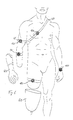
- FIG. 6 different locations of the device 100 are shown, for example, on the wrist, on the chest, on the upper arm, on the forearm or on the thigh. It is also possible to arrange the device directly in a prosthetic device 50, 60, for example in a forearm prosthesis 50 or in a thigh shaft 60 of a leg prosthesis.
- FIG. 7 shows a frequency modulation and an amplitude modulation.
- the positive and negative acceleration a means that either the direction of rotation is reversed or the mass m is accelerated and decelerated by a basic speed.
- an amplitude modulation is shown in which the measure of the acceleration a is varied without changing the frequency.
- this leads to the fact that first a weak vibration is transmitted to the user, which is increased with increasing time, until it then swells again after reaching the maximum.
- a prosthetic device 50, 60 for example, the current grip force
- other data can be forwarded via the device 100 to the user, for example, state data on temperature, power, operating modes, battery conditions or the like.
- myoelectric data which are recorded via lead electrodes, can be processed and passed on to the user as vibration signals, for example, in order to be able to carry out optimized training.
Landscapes
- Health & Medical Sciences (AREA)
- Engineering & Computer Science (AREA)
- Life Sciences & Earth Sciences (AREA)
- General Health & Medical Sciences (AREA)
- Animal Behavior & Ethology (AREA)
- Biomedical Technology (AREA)
- Heart & Thoracic Surgery (AREA)
- Veterinary Medicine (AREA)
- Public Health (AREA)
- Oral & Maxillofacial Surgery (AREA)
- Cardiology (AREA)
- Transplantation (AREA)
- Vascular Medicine (AREA)
- Surgery (AREA)
- Nuclear Medicine, Radiotherapy & Molecular Imaging (AREA)
- Robotics (AREA)
- Medical Informatics (AREA)
- Molecular Biology (AREA)
- Prostheses (AREA)
- User Interface Of Digital Computer (AREA)
- Rehabilitation Tools (AREA)
Description
- Die Erfindung betrifft eine Vorrichtung und ein Verfahren zur Erzeugung eines Vibrationsmusters bei einer Person mit einem Antrieb, der eine Masse in eine Drehbewegung versetzt, sowie zumindest einer Sensoreinrichtung, die mit einer Steuerung gekoppelt ist, die den Antrieb in Abhängigkeit von Sensordaten der Sensoreinrichtung steuert.
- Die
US 5,413,611 beschreibt eine Prothese mit einer Feedback-Einrichtung. Über einen Vibrationserzeuger wird eine Rückmeldung über die aufgebrachte Kraft einer angetriebenen Prothese erzeugt. - Die
US 2002/0052663 A1 betrifft eine Protheseneinrichtung mit einem Prothesenkniegelenk und einem Vibrationsgenerator zur Erzeugung eines Warnsignals. Der Vibrationsgenerator kann als Taumelmotor oder Wubbelmotor ausgebildet sein. - Die
US 2004/0178989 A1 beschreibt ein System und ein Verfahren zum Bereitstellen einer haptischen Rückkopplung, bei der ein Motor mit einer exzentrisch angeordneten Masse in Bewegung versetzt wird, um ein Vibrationsmuster zu erzeugen. Eine ähnliche Einrichtung ist in derWO 03/091984 A1 - Aufgabe der vorliegenden Erfindung ist es, eine Vorrichtung zur Erzeugung eines Vibrationsmusters und ein Verfahren bereitzustellen, bei dem komplexe Feedbackmuster leicht erzeugt werden können. Erfindungsgemäß wird dies durch eine Vorrichtung mit den Merkmalen des Hauptanspruches und durch ein Verfahren mit den Merkmalen des nebengeordneten Anspruchs gelöst. Vorteilhafte Ausgestaltungen und Weiterbildungen der Erfindung sind in den Unteransprüchen aufgeführt.
- Die erfindungsgemäße Vorrichtung zur Erzeugung eines Vibrationsmuster bei einer Person mit einem Antrieb, der eine Masse in eine Drehbewegung versetzt, sowie zumindest einer Sensoreinrichtung, die mit einer Steuerung gekoppelt ist, die den Antrieb in Abhängigkeit von Sensordaten der Sensoreinrichtung steuert, sieht vor, dass die Masse konzentrisch homogen um ihre Drehachse herum angeordnet ist und dass die Vorrichtung eine Schnittstelle aufweist, die Reaktionskräfte der Masse, die aufgrund der Veränderung der Drehbewegung entstehen, auf den Patienten überträgt. Die Vorrichtung weist eine homogene konzentrische Masse auf, die von einem Antrieb in eine Drehbewegung versetzt wird. Die Erzeugung des Vibrationsmusters basiert dabei auf dem Prinzip der Aktion-Reaktion. Durch das Beschleunigen der rotierenden Masse entsteht eine gerichtete Trägheitskraft, die einen Stator, um den die konzentrische Masse dreht, zu einer Gegenbewegung veranlasst. Die dabei entstehende Reaktionskraft erzeugt ein für den Benutzer spürbares Feedback.
- Vorzugsweise ist die rotierende Masse als ein Rotor ausgebildet, der um einen Stator des Antriebes herum gelagert ist, sodass die Vorrichtung sehr kleinbauend ausgebildet werden kann.
- Die Sensoreinrichtung, die die Daten liefert, auf deren Grundlage die Steuereinheit errechnet, wie groß der überstrichene Rotorwinkel, die Winkelgeschwindigkeit und die Beschleunigung sein müssen, können als Drucksensor, Lagesensor, Momentsensor, Bewegungssensor und/oder Temperatursensor ausgebildet sein. Dadurch ist es möglich, eine Vielzahl an Einflüssen aufzunehmen und mittels eines Vibrationsmusters an den Nutzer der Vorrichtung zu übertragen.
- Beispielsweise kann die Sensoreinrichtung ebenso wie die Vibrationseinrichtung in oder an einer Exoprothese angeordnet oder mit einer Exoporthese gekoppelt sein. So ist es beispielsweise möglich, Zustände der Prothesenelemente innerhalb der Exoprothese zu verarbeiten und über die Vorrichtung auf den Stumpf oder die Befestigungsstelle der Prothese an den Körper zu übertragen. Alternative Anbringungsorte der Vorrichtung stehen ebenfalls zur Verfügung, grundsätzlich sind alle ausreichend empfindlichen Körperstellen dazu geeignet.
- An der Vorrichtung kann eine Befestigungsanordnung zum Anbringen der Vorrichtung an der Person angeordnet sein. Die Befestigungsanordnung kann als Gurt, Manschette oder Spange ausgebildet sein. Ebenfalls ist es möglich, dass über ein Kopplungsmittel das Vibrationsmuster auf den Körper übertragen wird. Das Kopplungsmittel kann die Vibration konzentrieren, beispielsweise indem der Stator über einen Ausleger oder eine Einrichtung mit einer Auflagefläche, die kleiner als der Stator ist, mit dem Nutzer der Vorrichtung gekoppelt wird. Das Kopplungselement, das die Reaktionskräfte der Masse auf die Person überträgt, kann abnehmbar an der Vorrichtung angeordnet oder ein integraler Bestandteil der Vorrichtung sein. Sofern das Kopplungselement über einen Hebel mit einem Stator des Antriebes verbunden ist, kann eine Vibrationsübertragung angepasst erfolgen. Ebenfalls ist es möglich, durch eine Hebelanordnung eine Getriebeübersetzung vorzunehmen, über die eine Amplitudenverstärkung durchgeführt wird.
- Das erfindungsgemäße Verfahren zur Erzeugung eines Feedback-Signals, bei dem über zumindest eine Sensoreinrichtung ein Sensorsignal bereitgestellt wird und eine konzentrisch und homogen um eine in Drehachse angeordnete Masse in Abhängigkeit von dem Sensorsignal angetrieben wird, sieht vor, dass ein frequenz- und/oder amplitudenmoduliertes Feedbackmuster erzeugt wird. Die Masse wird dabei in unterschiedlichen Drehrichtungen und mit unterschiedlichen Winkelgeschwindigkeiten angetrieben, je nach Sensorsignal und korrespondierend dazu zu erzeugendem Feedbackmuster. Die Masse zur Erzeugung des Feedbackmusters wird in Abhängigkeit von dem Sensorsignal in unterschiedlichen Beschleunigungsmustern angetrieben, wobei die Beschleunigungsmuster sowohl in einer Frequenzmodulation als auch in einer Amplitudenmodulation variiert werden können. Die Amplitudenmodulation wird durch die Beschleunigung des Rotors geregelt. Die Regelung der Beschleunigung wird aufgrund gemessener Bewegungsgrößen des Rotors durchgeführt, je stärker die Beschleunigung des Rotors ist, desto höher ist die Amplitude der Stimulation. Die Frequenz ist eine Funktion der Winkelgeschwindigkeit und des überstrichenen Rotorwinkels. Durch Synchronisation der Winkelgeschwindigkeit mit den überstrichenen Rotorwinkeln ist es möglich, die Frequenz der Stimulation in der gewünschten Weise zu modulieren. Dabei kann die Frequenz konstant oder variabel sein.
- Es ist möglich, dass das Signal zeitabhängig oder in Abhängigkeit von einem Zustand der Vorrichtung oder deren Anbauteile erzeugt wird. Die Vorrichtung kann durch bestimmte Zustände, beispielsweise der Prothese, angetriggert werden. Beispielsweise kann durch eine automatische Umschaltung der Prothese in einen anderen Modus die Information über ein anderes Prothesenverhalten durch ein entsprechendes Signal an den Prothesenträger weitergegeben werden. Ebenfalls ist es möglich, bestimmte Zustände, beispielsweise einen Ladezustand eines Akkumulators, einen eingeschalteten Prothesenzustand oder eine Überhitzung von Prothesenkomponenten, durch ein entsprechendes Vibrationsmuster anzuzeigen.
- Grundsätzlich ist es auch möglich, die Vorrichtung mit einer Prothese über ein Kabel oder über eine Funkstrecke zu verbinden. Dadurch ist es möglich, Zustände, die innerhalb einer Prothese ermittelt werden, an einer entfernten Stelle über ein Vibrationsmuster zu übermitteln. Dabei ist die Anwendung der Vorrichtung nicht auf die Übermittlung von Daten betreffend eine Prothese beschränkt. Ebenfalls ist es möglich, ein Feedback von Trainingsgeräten zu erhalten oder aber auch ein Feedback von myoelektrischen Signalen, die von entsprechenden Ableiterelektroden erfasst wurden.
- Nachfolgend werden Ausführungsbeispiele der Erfindung anhand der beigefügten Figuren näher erläutert. Es zeigen:
- Figur 1 -
- eine Darstellung der Funktionsweise der Vorrichtung;
- Figur 2 -
- eine perspektivische Ansicht eines Vibrationserzeugers;
- Figur 3 -
- eine Schnittansicht;
- Figur 4 -
- eine schematische Darstellung einer Vorrichtung;
- Figur 5 -
- eine Darstellung einer angelegten Vorrichtung;
- Figur 6 -
- unterschiedliche Anordnungen an einer Person; sowie
- Figur 7 -
- Darstellungen von Frequenz- und Amplitudenmodulationen.
- In der
Figur 1 ist der prinzipielle Aufbau einer Vorrichtung zur Erzeugung eines Vibrationsmusters gemäß der vorliegenden Erfindung dargestellt. Die Vorrichtung weist eine homogene, konzentrische Masse m auf, die von einem elektrischen Antrieb, der nicht dargestellt ist, mit einem überstrichenen Rotorwinkel Δθ, der Winkelgeschwindigkeit ω und der Beschleunigung a = dω/dt gedreht wird. Der überstrichene Rotorwinkel Δθ bzw. die Winkelgeschwindigkeit ω werden entweder über Sensoren unmittelbar gemessen oder indirekt durch eine Umrechnung der Rotorbewegungsgrößen ermittelt. Die ermittelte Rotorposition bzw. die momentane Winkelgeschwindigkeit werden von der nicht dargestellten Motorsteuereinheit genutzt, um vorgegebene Vibrationsmuster auf der Grundlage von Sensordaten, die von einer Sensoreinrichtung bereitgestellt werden, die nicht die Rotorbewegungen ermittelt, zu erzeugen. Es handelt sich also um eine Einrichtung zur Übermittlung eines Feedbacks über Vibrationsmuster, wobei die Erzeugung des Feedbacks auf dem Prinzip der Aktion-Reaktion basiert. Durch das Beschleunigen der rotierenden Masse m entsteht eine gerichtete Trägheitskraft Fa gemäß der Formel Fa = m * a. Diese gerichtete Trägheitskraft Fa veranlasst den Stator 15 des Motors zu einer Gegenbewegung. Die dabei entstehende Reaktionskraft erzeugt ein für den Benutzer spürbaren Impuls und damit ein Feedback. - In der
Figur 2 ist in einer perspektivischen Darstellung einer Ausführungsform die rotierende Masse m in Gestalt eines Ringes gegeben, der konzentrisch und homogen um die Drehachse 10 herum angeordnet ist. Die Drehachse 10 liegt im Zentrum eines Stators 15, der als Stator eines Motors ausgebildet ist. Die Masse m ist also Teil des Antriebes, nämlich Teil eines Elektromotors. Neben der dargestellten integrierten Lösung, bei der die Masse m nicht separat gelagert ist, besteht die Möglichkeit, dass der Antrieb über eine Getriebe oder eine Übersetzung mit der drehbar gelagerten Masse m gekoppelt ist. Um den Stator 15 herum ist der bewegliche Rotor als rotierende Masse m angeordnet, sodass sich hier die Bauform des Außenläufer-Elektromotors ergibt. Die rotierende Masse m kann bei der Ausgestaltung als elektronisch kommutierter Gleichstrommotor aus ringförmig angeordneten Dauermagneten bestehen oder diese aufweisen, um die Drehbewegung der rotierenden Masse m zu erzeugen. Durch eine entsprechende Ansteuerung der Erregerspulen innerhalb des Stators 15 ist es möglich, ein Vibrationsmuster als Feedbackmuster amplituden- und/oder frequenzmoduliert zu erzeugen. Zusätzlich ermöglicht es die Überlagerung von mehreren modulierten Feedbackmustern und dadurch die Erzeugung einer großen Variation hochkomplexer Feedbackmuster, sodass eine Vielzahl von Sensordaten unterschiedlichster Art über unterschiedlichste Feedbackmuster einfach und zuverlässig an den Nutzer der Vorrichtung 100 weitergegeben werden können. - Die Amplitudenmodulation wird durch die Beschleunigung des Rotors m geregelt. Befindet sich die rotierende Masse m bereits in einer Drehbewegung, wird der gegenwärtige Zustand durch die Motorsteuerung erfasst. Auf der Grundlage der gemessenen oder ermittelten Bewegungsgrößen der rotierenden Masse m wird dann die Regelung der Beschleunigung durchgeführt, sodass aufgrund der Veränderung der Winkelgeschwindigkeit die gerichtete Trägheitskraft Fa erzeugt wird, die sich über den Stator 15 auf den Nutzer der Vorrichtung 100 übertragen lässt. Je stärker die Beschleunigung der rotierenden Masse m, also sowohl im Sinne einer positiven als auch einer negativen Beschleunigung, desto höher ist die Amplitude der Stimulation und die Vibrationsamplitude. Steht die Masse m anfänglich still, wird der entsprechende Vibrationseffekt durch Beschleunigen in die eine und/oder andere Richtung erreicht.
- Die Frequenz der erzeugten Vibration ist eine Funktion der Winkelgeschwindigkeit ω und des überstrichenen Rotorwinkels Δθ. Durch Synchronisation der Winkelgeschwindigkeit ω mit den überstrichenen Rotorwinkeln Δθ ist es möglich, die Frequenz der Stimulation in der gewünschten Weise zu modulieren. Die Frequenz kann dabei entweder konstant oder variabel sein. Die Frequenz der Stimulation ergibt sich aus dem Quotienten der Winkelgeschwindigkeit ω zu dem überstrichenen Rotorwinkel Δθ.
- In der
Figur 4 ist die Vorrichtung 100 vergrößert und schematisch gezeigt. Die Vorrichtung 100 ist dabei auf der Hautoberfläche 30 eines Nutzers angeordnet. Die rotierende Masse m dreht sich um die Drehachse 10, um die herum der Stator 15 angeordnet ist. Die Vorrichtung 100 sieht im dargestellten Ausführungsbeispiel vor, dass die Masse m Teil des Antriebs ist, nämlich des Elektromotors aus Stator 15 und die Masse m ausbildenden Rotor. Der Stator 15 des Motors generiert ein magnetisches Drehfeld, aufgrund dessen die rotierende Masse m in Abhängigkeit von der Art des Drehfeldes gedreht wird. Der Stator 15 ist dabei an einem Gehäuse 20 festgelegt, das die Schnittstelle zwischen der Vorrichtung 100 und der Hautoberfläche 30 bildet. Je nach Drehrichtung, Frequenz und Amplitude der Änderung wird ein entsprechendes Muster an Reaktionskräften und damit an Vibrationen erzeugt. - In der
Figur 5 ist dabei die Vorrichtung 100 im angelegten Zustand gezeigt. In derFigur 5 ist die Vorrichtung 100 an einem Oberarm über eine Befestigungsanordnung 40 in Gestalt einer Manschette angelegt. In derFigur 5 sind auch die wirkenden Momente gezeigt. Das Reaktionsmoment Mr wird von der rotierenden Masse m auf die Schnittstelle, also auf das Gehäuse 20 ausgeübt. Die Größe des Momentes Mr wird durch das Trägheitsmoment der rotierenden, homogenen konzentrischen Masse m und der darauf einwirkenden Kraft bzw. Beschleunigung definiert. - In der
Figur 6 sind unterschiedliche Anbringungsstellen der Vorrichtung 100 gezeigt, beispielsweise am Handgelenk, am Brustkorb, am Oberarm, am Unterarm oder am Oberschenkel. Ebenfalls ist es möglich, die Vorrichtung unmittelbar in einer Protheseneinrichtung 50, 60 anzuordnen, beispielsweise in einer Unterarmprothese 50 oder in einem Oberschenkelschaft 60 einer Beinprothese. - In der Figur 7 sind eine Frequenzmodulation und eine Amplitudenmodulation dargestellt. Bei einer sprungweise, in ihrem Betrag gleichbleibenden Beschleunigung a verändert sich die Stärke des Vibrationsimpulses nicht, da über den Verlauf der Zeit das Beschleunigen bzw. Abbremsen oder die Bewegungsumkehr in immer kürzeren Zeitabständen erfolgt, erhöht sich die Vibrationsfrequenz, sodass der Nutzer der Vorrichtung ein Feedback erhält, das in Abhängigkeit von den gemessenen Sensorsignalen erzeugt wird. Die positive und negative Beschleunigung a bedeutet, dass entweder die Drehrichtung umgekehrt oder die Masse m um eine Grundgeschwindigkeit herum beschleunigt und abgebremst wird.
- In der rechten Darstellung der Figur 7 ist hingegen eine Amplitudenmodulation gezeigt, bei der das Maß der Beschleunigung a variiert wird, ohne die Frequenz zu verändern. In dem dargestellten Ausführungsbeispiel führt dies dazu, dass zunächst eine schwache Vibration auf den Nutzer übertragen wird, die mit zunehmenden Zeitablauf vergrößert wird, bis sie dann nach Erreichen des Maximums wieder abschwillt. Durch eine Überlagerung der Frequenzmodulation und der Amplitudenmodulation können vielfältige Signalmuster erzeugt und auf den Nutzer der Vorrichtung übertragen werden.
- Neben Daten, beispielsweise zum Zustand einer Protheseneinrichtung 50, 60, beispielsweise der aktuellen Griffkraft, können andere Daten über die Vorrichtung 100 an den Nutzer weitergeleitet werden, beispielsweise Zustandsdaten über Temperatur, Einschaltzustände, Betriebsmodi, Batteriezustände oder dergleichen. Ebenfalls können myoelektrische Daten, die über Ableiterelektroden aufgenommen werden, verarbeitet und als Vibrationssignale an den Nutzer weitergegeben werden, beispielsweise um ein optimiertes Training durchführen zu können.
Claims (14)
- Vorrichtung zur Erzeugung eines Vibrationsmusters bei einer Person mit einem Antrieb, der eine Masse in eine Drehbewegung versetzt, sowie zumindest einer Sensoreinrichtung, die mit einer Steuerung gekoppelt ist, die den Antrieb in Abhängigkeit von Sensordaten der Sensoreinrichtung steuert, dadurch gekennzeichnet, dass die Masse (m) konzentrisch homogen um ihre Drehachse (10) herum angeordnet ist und dass eine Schnittstelle (20) Reaktionskräfte der Masse (m), die aufgrund der Veränderung der Drehbewegung entstehen, auf die Person überträgt.
- Vorrichtung nach Anspruch 1, dadurch gekennzeichnet, dass der Antrieb ein Elektromotor ist.
- Vorrichtung nach Anspruch 1 oder 2, dadurch gekennzeichnet, dass die rotierende Masse (m) als Rotor ausgebildet ist, der um einen Stator (15) des Antriebes herum gelagert ist.
- Vorrichtung nach einem der voranstehenden Ansprüche, dadurch gekennzeichnet, dass die Sensoreinrichtung als Drucksensor, Lagesensor, Momentensensor, Bewegungssensor und/oder Temperatursensor ausgebildet ist.
- Vorrichtung nach einem der voranstehenden Ansprüche, dadurch gekennzeichnet, dass die Sensoreinrichtung in einer Exoprothese (50, 60) angeordnet ist.
- Vorrichtung nach einem der voranstehenden Ansprüche, dadurch gekennzeichnet, dass die Vorrichtung (100) in oder an einer Exoprothese (50, 60) angeordnet oder mit der Exoprothese (50, 60) gekoppelt ist.
- Vorrichtung nach einem der voranstehenden Ansprüche, dadurch gekennzeichnet, dass eine Befestigungsanordnung (40) zum Anbringen der Vorrichtung (100) an der Person vorgesehen ist.
- Vorrichtung nach einem der voranstehenden Ansprüche, dadurch gekennzeichnet, dass zumindest ein Kopplungselement vorgesehen ist, das die Reaktionskräfte der Masse (m) auf die Person überträgt.
- Vorrichtung nach Anspruch 8, dadurch gekennzeichnet, dass das Kopplungselement über einen Hebel mit einem Stator (15) des Antriebes verbunden ist.
- Verfahren zur Erzeugung eines Feedback-Signals, bei dem über zumindest eine Sensoreinrichtung ein Sensorsignal bereitgestellt wird und eine konzentrisch und homogen um eine Drehachse angeordnete Masse (m) in Abhängigkeit von dem Sensorsignal angetrieben wird, um durch Reaktionskräfte der Masse (m) ein frequenz- und/oder amplitudenmoduliertes Feedbackmuster zu erzeugen.
- Verfahren nach Anspruch 10, dadurch gekennzeichnet, dass die Masse in unterschiedlichen Drehrichtungen angetrieben wird.
- Verfahren nach Anspruch 10 oder 11, dadurch gekennzeichnet, dass die Masse zur Erzeugung des Feedback-Signals in Abhängigkeit von dem Sensorsignal in unterschiedlichen Beschleunigungsmustern angetrieben wird.
- Verfahren nach einem der Ansprüche 10 bis 12, dadurch gekennzeichnet, dass mehrere Feedbackmuster einander überlagert werden.
- Verfahren nach einem der Ansprüche 10 bis 14, dadurch gekennzeichnet, dass das Sensorsignal zeitabhängig oder in Abhängigkeit von einem Zustand der Vorrichtung oder deren Anbauteile erzeugt wird.
Applications Claiming Priority (2)
| Application Number | Priority Date | Filing Date | Title |
|---|---|---|---|
| DE102009034708A DE102009034708A1 (de) | 2009-07-24 | 2009-07-24 | Vorrichtung und ein Verfahren zur Erzeugung eines Vibrationsmusters |
| PCT/EP2010/004386 WO2011009576A1 (de) | 2009-07-24 | 2010-07-19 | Vorrichtung und ein verfahren zur erzeugung eines vibrationsmusters |
Publications (2)
| Publication Number | Publication Date |
|---|---|
| EP2456397A1 EP2456397A1 (de) | 2012-05-30 |
| EP2456397B1 true EP2456397B1 (de) | 2013-06-12 |
Family
ID=42937662
Family Applications (1)
| Application Number | Title | Priority Date | Filing Date |
|---|---|---|---|
| EP10736622.1A Active EP2456397B1 (de) | 2009-07-24 | 2010-07-19 | Vorrichtung und ein verfahren zur erzeugung eines vibrationsmusters |
Country Status (4)
| Country | Link |
|---|---|
| US (1) | US9827116B2 (de) |
| EP (1) | EP2456397B1 (de) |
| DE (1) | DE102009034708A1 (de) |
| WO (1) | WO2011009576A1 (de) |
Families Citing this family (2)
| Publication number | Priority date | Publication date | Assignee | Title |
|---|---|---|---|---|
| DE102009049465B4 (de) * | 2009-10-15 | 2015-11-26 | Molla-Ahmadi Nader | Verwendung einer Vibrationsmanschette zur optimierten Anpassung und Erleichterung der Anprobe von Prothesen |
| GB2598596B (en) * | 2020-09-03 | 2022-08-24 | Theia Guidance Systems Ltd | Mobility assistance device and method of providing mobility assistance |
Family Cites Families (13)
| Publication number | Priority date | Publication date | Assignee | Title |
|---|---|---|---|---|
| US5413611A (en) | 1992-07-21 | 1995-05-09 | Mcp Services, Inc. | Computerized electronic prosthesis apparatus and method |
| US6500210B1 (en) * | 1992-09-08 | 2002-12-31 | Seattle Systems, Inc. | System and method for providing a sense of feel in a prosthetic or sensory impaired limb |
| DE60131377T2 (de) | 2000-03-29 | 2008-09-04 | Massachusetts Institute Of Technology, Cambridge | Geschwindigkeitsangepasste und patientenangepasste knieprothese |
| US6504285B2 (en) * | 2001-02-08 | 2003-01-07 | Jae Shin Yun | Vector motor |
| US7161580B2 (en) | 2002-04-25 | 2007-01-09 | Immersion Corporation | Haptic feedback using rotary harmonic moving mass |
| AU2003286504A1 (en) | 2002-10-20 | 2004-05-13 | Immersion Corporation | System and method for providing rotational haptic feedback |
| WO2007021931A2 (en) * | 2005-08-11 | 2007-02-22 | Rehabilitation Institute Of Chicago | System and method for improving the functionality of prostheses |
| US8398569B1 (en) * | 2006-04-14 | 2013-03-19 | Engineering Acoustics, Inc. | Apparatus for generating a vibrational stimulus using a rotating mass motor |
| CA2679633C (en) * | 2007-02-06 | 2017-07-11 | Christopher C. Langenfeld | Arm prosthetic device |
| US20080200994A1 (en) * | 2007-02-21 | 2008-08-21 | Colgate J Edward | Detector and Stimulator for Feedback in a Prosthesis |
| US8469908B2 (en) * | 2007-04-06 | 2013-06-25 | Wilson T. Asfora | Analgesic implant device and system |
| US8475172B2 (en) * | 2007-07-19 | 2013-07-02 | Massachusetts Institute Of Technology | Motor learning and rehabilitation using tactile feedback |
| US8040223B2 (en) * | 2007-11-21 | 2011-10-18 | Engineering Acoustics, Inc. | Device and method for enhancing sensory perception of vibrational stimuli |
-
2009
- 2009-07-24 DE DE102009034708A patent/DE102009034708A1/de not_active Withdrawn
-
2010
- 2010-07-19 US US13/386,727 patent/US9827116B2/en not_active Expired - Fee Related
- 2010-07-19 WO PCT/EP2010/004386 patent/WO2011009576A1/de not_active Ceased
- 2010-07-19 EP EP10736622.1A patent/EP2456397B1/de active Active
Also Published As
| Publication number | Publication date |
|---|---|
| US9827116B2 (en) | 2017-11-28 |
| DE102009034708A1 (de) | 2011-01-27 |
| US20120119891A1 (en) | 2012-05-17 |
| EP2456397A1 (de) | 2012-05-30 |
| WO2011009576A1 (de) | 2011-01-27 |
Similar Documents
| Publication | Publication Date | Title |
|---|---|---|
| EP3490664B1 (de) | Orthopädietechnisches system | |
| EP2528549B1 (de) | Verstelleinrichtung und verfahren zum betreiben einer verstelleinrichtung | |
| DE19638695B4 (de) | Modularer Schwingungskraftgenerator und Verfahren zu dessen Betrieb | |
| EP2791423B1 (de) | Vorrichtung zur erfassung der bewegung einer verdichterwalze eines bodenverdichters | |
| EP2160168B1 (de) | Vorrichtung und verfahren für ein training und/oder eine analyse des bewegungsapparats eines benutzers | |
| WO2016120110A1 (de) | Teleoperationssystem mit intrinsischem haptischen feedback durch dynamische kennlinienanpassung für greifkraft und endeffektorkoordinaten | |
| dos Santos et al. | Impedance control of a rotary series elastic actuator for knee rehabilitation | |
| DE2219155A1 (de) | Stellsystem | |
| EP2456397B1 (de) | Vorrichtung und ein verfahren zur erzeugung eines vibrationsmusters | |
| CN106389073A (zh) | 外骨骼机械装置 | |
| EP3911282A1 (de) | Verfahren zur steuerung einer orthetischen oder prothetischen einrichtung und orthetische oder prothetische einrichtung | |
| EP3727211B1 (de) | System aus zumindest einer orthopädietechnischen komponente und einer bedien- und/oder feedbackeinrichtung | |
| DE102012213365A1 (de) | Piezo-angetriebenes Exoskelett | |
| DE102015110852B3 (de) | Gelenkverbindung mit einer Antriebseinrichtung sowie Verfahren zur Ansteuerung einer Schwenkbewegung einer Gelenkverbindung | |
| EP2392413B1 (de) | Vibrationsramme | |
| DE102013217184B4 (de) | Betätigungseinrichtung | |
| EP3934816B1 (de) | Schwingungserzeuger sowie baumaschine mit einem solchen schwingungserzeuger | |
| EP2067533A1 (de) | Schwingungserzeuger für ein Vibrationsrammgerät | |
| WO2021259986A1 (de) | Protheseneinrichtung mit einer prothesenhand und verfahren zum betreiben einer protheseneinrichtung | |
| EP4312896B1 (de) | Prothesenschaftsystem und verfahren zu dessen herstellung | |
| WO2020083696A1 (de) | Orthopädietechnisches gelenk und orthopädietechnische einrichtung | |
| CH703610B1 (de) | Modulares Trainingssystem zur Rehabilitation von physiologisch beeinträchtigten Patienten. | |
| WO2004019834A1 (de) | Vorrichtung zur bewegungsbeeinflussung mit einem parallelmechanismus | |
| AT522226B1 (de) | Fremdkraftbetriebene Bewegungseinheit | |
| DE10308210A1 (de) | Trainingsgerät sowie Verfahren zum Betreiben eines Trainingsgerätes |
Legal Events
| Date | Code | Title | Description |
|---|---|---|---|
| PUAI | Public reference made under article 153(3) epc to a published international application that has entered the european phase |
Free format text: ORIGINAL CODE: 0009012 |
|
| 17P | Request for examination filed |
Effective date: 20120118 |
|
| AK | Designated contracting states |
Kind code of ref document: A1 Designated state(s): AL AT BE BG CH CY CZ DE DK EE ES FI FR GB GR HR HU IE IS IT LI LT LU LV MC MK MT NL NO PL PT RO SE SI SK SM TR |
|
| DAX | Request for extension of the european patent (deleted) | ||
| GRAP | Despatch of communication of intention to grant a patent |
Free format text: ORIGINAL CODE: EPIDOSNIGR1 |
|
| GRAS | Grant fee paid |
Free format text: ORIGINAL CODE: EPIDOSNIGR3 |
|
| GRAA | (expected) grant |
Free format text: ORIGINAL CODE: 0009210 |
|
| AK | Designated contracting states |
Kind code of ref document: B1 Designated state(s): AL AT BE BG CH CY CZ DE DK EE ES FI FR GB GR HR HU IE IS IT LI LT LU LV MC MK MT NL NO PL PT RO SE SI SK SM TR |
|
| REG | Reference to a national code |
Ref country code: GB Ref legal event code: FG4D Free format text: NOT ENGLISH |
|
| REG | Reference to a national code |
Ref country code: CH Ref legal event code: EP |
|
| REG | Reference to a national code |
Ref country code: AT Ref legal event code: REF Ref document number: 616379 Country of ref document: AT Kind code of ref document: T Effective date: 20130615 |
|
| REG | Reference to a national code |
Ref country code: IE Ref legal event code: FG4D Free format text: LANGUAGE OF EP DOCUMENT: GERMAN |
|
| REG | Reference to a national code |
Ref country code: DE Ref legal event code: R096 Ref document number: 502010003668 Country of ref document: DE Effective date: 20130808 |
|
| REG | Reference to a national code |
Ref country code: SE Ref legal event code: TRGR |
|
| REG | Reference to a national code |
Ref country code: NL Ref legal event code: T3 |
|
| PG25 | Lapsed in a contracting state [announced via postgrant information from national office to epo] |
Ref country code: GR Free format text: LAPSE BECAUSE OF FAILURE TO SUBMIT A TRANSLATION OF THE DESCRIPTION OR TO PAY THE FEE WITHIN THE PRESCRIBED TIME-LIMIT Effective date: 20130913 Ref country code: NO Free format text: LAPSE BECAUSE OF FAILURE TO SUBMIT A TRANSLATION OF THE DESCRIPTION OR TO PAY THE FEE WITHIN THE PRESCRIBED TIME-LIMIT Effective date: 20130912 Ref country code: FI Free format text: LAPSE BECAUSE OF FAILURE TO SUBMIT A TRANSLATION OF THE DESCRIPTION OR TO PAY THE FEE WITHIN THE PRESCRIBED TIME-LIMIT Effective date: 20130612 Ref country code: LT Free format text: LAPSE BECAUSE OF FAILURE TO SUBMIT A TRANSLATION OF THE DESCRIPTION OR TO PAY THE FEE WITHIN THE PRESCRIBED TIME-LIMIT Effective date: 20130612 Ref country code: SI Free format text: LAPSE BECAUSE OF FAILURE TO SUBMIT A TRANSLATION OF THE DESCRIPTION OR TO PAY THE FEE WITHIN THE PRESCRIBED TIME-LIMIT Effective date: 20130612 Ref country code: ES Free format text: LAPSE BECAUSE OF FAILURE TO SUBMIT A TRANSLATION OF THE DESCRIPTION OR TO PAY THE FEE WITHIN THE PRESCRIBED TIME-LIMIT Effective date: 20130923 |
|
| REG | Reference to a national code |
Ref country code: LT Ref legal event code: MG4D |
|
| PG25 | Lapsed in a contracting state [announced via postgrant information from national office to epo] |
Ref country code: HR Free format text: LAPSE BECAUSE OF FAILURE TO SUBMIT A TRANSLATION OF THE DESCRIPTION OR TO PAY THE FEE WITHIN THE PRESCRIBED TIME-LIMIT Effective date: 20130612 Ref country code: BG Free format text: LAPSE BECAUSE OF FAILURE TO SUBMIT A TRANSLATION OF THE DESCRIPTION OR TO PAY THE FEE WITHIN THE PRESCRIBED TIME-LIMIT Effective date: 20130912 |
|
| PG25 | Lapsed in a contracting state [announced via postgrant information from national office to epo] |
Ref country code: LV Free format text: LAPSE BECAUSE OF FAILURE TO SUBMIT A TRANSLATION OF THE DESCRIPTION OR TO PAY THE FEE WITHIN THE PRESCRIBED TIME-LIMIT Effective date: 20130612 |
|
| BERE | Be: lapsed |
Owner name: OTTO BOCK HEALTHCARE PRODUCTS GMBH Effective date: 20130731 |
|
| PG25 | Lapsed in a contracting state [announced via postgrant information from national office to epo] |
Ref country code: EE Free format text: LAPSE BECAUSE OF FAILURE TO SUBMIT A TRANSLATION OF THE DESCRIPTION OR TO PAY THE FEE WITHIN THE PRESCRIBED TIME-LIMIT Effective date: 20130612 Ref country code: IS Free format text: LAPSE BECAUSE OF FAILURE TO SUBMIT A TRANSLATION OF THE DESCRIPTION OR TO PAY THE FEE WITHIN THE PRESCRIBED TIME-LIMIT Effective date: 20131012 Ref country code: PT Free format text: LAPSE BECAUSE OF FAILURE TO SUBMIT A TRANSLATION OF THE DESCRIPTION OR TO PAY THE FEE WITHIN THE PRESCRIBED TIME-LIMIT Effective date: 20131014 Ref country code: SK Free format text: LAPSE BECAUSE OF FAILURE TO SUBMIT A TRANSLATION OF THE DESCRIPTION OR TO PAY THE FEE WITHIN THE PRESCRIBED TIME-LIMIT Effective date: 20130612 Ref country code: CZ Free format text: LAPSE BECAUSE OF FAILURE TO SUBMIT A TRANSLATION OF THE DESCRIPTION OR TO PAY THE FEE WITHIN THE PRESCRIBED TIME-LIMIT Effective date: 20130612 |
|
| PG25 | Lapsed in a contracting state [announced via postgrant information from national office to epo] |
Ref country code: PL Free format text: LAPSE BECAUSE OF FAILURE TO SUBMIT A TRANSLATION OF THE DESCRIPTION OR TO PAY THE FEE WITHIN THE PRESCRIBED TIME-LIMIT Effective date: 20130612 Ref country code: RO Free format text: LAPSE BECAUSE OF FAILURE TO SUBMIT A TRANSLATION OF THE DESCRIPTION OR TO PAY THE FEE WITHIN THE PRESCRIBED TIME-LIMIT Effective date: 20130612 |
|
| PG25 | Lapsed in a contracting state [announced via postgrant information from national office to epo] |
Ref country code: MC Free format text: LAPSE BECAUSE OF FAILURE TO SUBMIT A TRANSLATION OF THE DESCRIPTION OR TO PAY THE FEE WITHIN THE PRESCRIBED TIME-LIMIT Effective date: 20130612 |
|
| PLBE | No opposition filed within time limit |
Free format text: ORIGINAL CODE: 0009261 |
|
| STAA | Information on the status of an ep patent application or granted ep patent |
Free format text: STATUS: NO OPPOSITION FILED WITHIN TIME LIMIT |
|
| REG | Reference to a national code |
Ref country code: IE Ref legal event code: MM4A |
|
| PG25 | Lapsed in a contracting state [announced via postgrant information from national office to epo] |
Ref country code: DK Free format text: LAPSE BECAUSE OF FAILURE TO SUBMIT A TRANSLATION OF THE DESCRIPTION OR TO PAY THE FEE WITHIN THE PRESCRIBED TIME-LIMIT Effective date: 20130612 Ref country code: BE Free format text: LAPSE BECAUSE OF NON-PAYMENT OF DUE FEES Effective date: 20130731 |
|
| 26N | No opposition filed |
Effective date: 20140313 |
|
| REG | Reference to a national code |
Ref country code: DE Ref legal event code: R097 Ref document number: 502010003668 Country of ref document: DE Effective date: 20140313 |
|
| PG25 | Lapsed in a contracting state [announced via postgrant information from national office to epo] |
Ref country code: IE Free format text: LAPSE BECAUSE OF NON-PAYMENT OF DUE FEES Effective date: 20130719 |
|
| REG | Reference to a national code |
Ref country code: CH Ref legal event code: PL |
|
| PG25 | Lapsed in a contracting state [announced via postgrant information from national office to epo] |
Ref country code: CH Free format text: LAPSE BECAUSE OF NON-PAYMENT OF DUE FEES Effective date: 20140731 Ref country code: LI Free format text: LAPSE BECAUSE OF NON-PAYMENT OF DUE FEES Effective date: 20140731 |
|
| PG25 | Lapsed in a contracting state [announced via postgrant information from national office to epo] |
Ref country code: SM Free format text: LAPSE BECAUSE OF FAILURE TO SUBMIT A TRANSLATION OF THE DESCRIPTION OR TO PAY THE FEE WITHIN THE PRESCRIBED TIME-LIMIT Effective date: 20130612 |
|
| PG25 | Lapsed in a contracting state [announced via postgrant information from national office to epo] |
Ref country code: MT Free format text: LAPSE BECAUSE OF FAILURE TO SUBMIT A TRANSLATION OF THE DESCRIPTION OR TO PAY THE FEE WITHIN THE PRESCRIBED TIME-LIMIT Effective date: 20130612 Ref country code: CY Free format text: LAPSE BECAUSE OF FAILURE TO SUBMIT A TRANSLATION OF THE DESCRIPTION OR TO PAY THE FEE WITHIN THE PRESCRIBED TIME-LIMIT Effective date: 20130612 |
|
| PG25 | Lapsed in a contracting state [announced via postgrant information from national office to epo] |
Ref country code: MK Free format text: LAPSE BECAUSE OF FAILURE TO SUBMIT A TRANSLATION OF THE DESCRIPTION OR TO PAY THE FEE WITHIN THE PRESCRIBED TIME-LIMIT Effective date: 20130612 Ref country code: HU Free format text: LAPSE BECAUSE OF FAILURE TO SUBMIT A TRANSLATION OF THE DESCRIPTION OR TO PAY THE FEE WITHIN THE PRESCRIBED TIME-LIMIT; INVALID AB INITIO Effective date: 20100719 Ref country code: LU Free format text: LAPSE BECAUSE OF NON-PAYMENT OF DUE FEES Effective date: 20130719 |
|
| REG | Reference to a national code |
Ref country code: DE Ref legal event code: R082 Ref document number: 502010003668 Country of ref document: DE Representative=s name: GRAMM, LINS & PARTNER PATENT- UND RECHTSANWAEL, DE |
|
| REG | Reference to a national code |
Ref country code: FR Ref legal event code: PLFP Year of fee payment: 7 |
|
| REG | Reference to a national code |
Ref country code: AT Ref legal event code: MM01 Ref document number: 616379 Country of ref document: AT Kind code of ref document: T Effective date: 20150719 |
|
| PG25 | Lapsed in a contracting state [announced via postgrant information from national office to epo] |
Ref country code: AT Free format text: LAPSE BECAUSE OF NON-PAYMENT OF DUE FEES Effective date: 20150719 |
|
| REG | Reference to a national code |
Ref country code: FR Ref legal event code: PLFP Year of fee payment: 8 |
|
| REG | Reference to a national code |
Ref country code: FR Ref legal event code: PLFP Year of fee payment: 9 |
|
| PG25 | Lapsed in a contracting state [announced via postgrant information from national office to epo] |
Ref country code: AL Free format text: LAPSE BECAUSE OF FAILURE TO SUBMIT A TRANSLATION OF THE DESCRIPTION OR TO PAY THE FEE WITHIN THE PRESCRIBED TIME-LIMIT Effective date: 20130612 |
|
| PGFP | Annual fee paid to national office [announced via postgrant information from national office to epo] |
Ref country code: TR Payment date: 20230717 Year of fee payment: 14 Ref country code: IT Payment date: 20230731 Year of fee payment: 14 |
|
| PGFP | Annual fee paid to national office [announced via postgrant information from national office to epo] |
Ref country code: NL Payment date: 20240722 Year of fee payment: 15 |
|
| PGFP | Annual fee paid to national office [announced via postgrant information from national office to epo] |
Ref country code: GB Payment date: 20240723 Year of fee payment: 15 |
|
| PGFP | Annual fee paid to national office [announced via postgrant information from national office to epo] |
Ref country code: FR Payment date: 20240724 Year of fee payment: 15 |
|
| PGFP | Annual fee paid to national office [announced via postgrant information from national office to epo] |
Ref country code: SE Payment date: 20240722 Year of fee payment: 15 |
|
| PG25 | Lapsed in a contracting state [announced via postgrant information from national office to epo] |
Ref country code: IT Free format text: LAPSE BECAUSE OF NON-PAYMENT OF DUE FEES Effective date: 20240719 |
|
| PGFP | Annual fee paid to national office [announced via postgrant information from national office to epo] |
Ref country code: DE Payment date: 20250722 Year of fee payment: 16 |
|
| REG | Reference to a national code |
Ref country code: NL Ref legal event code: MM Effective date: 20250801 |